- Preface
- New and Changed QoS Features
- Modular QoS Overview
- Configuring Modular QoS Congestion Avoidance
- Configuring Modular QoS Congestion Management
- Configuring Modular QoS Service Packet Classification
- Modular QoS Deployment Scenarios
- Configuring Fabric QoS Policies and Classes
- Configuring Modular QoS on Link Bundles
- Index
- Prerequisites for Configuring Modular QoS Packet Classification
- Information About Configuring Modular QoS Packet Classification
- Packet Classification Overview
- Traffic Class Elements
- Traffic Policy Elements
- Default Traffic Class
- Shared Policy Instance
- Port Shape Policies
- Class-based Unconditional Packet Marking Feature and Benefits
- Specification of the CoS for a Packet with IP Precedence
- IP Precedence Compared to IP DSCP Marking
- QoS Policy Propagation Using Border Gateway Protocol
- QoS on the Satellite System
- ACL Deny
- Hierarchical Ingress Policing
- Enhanced Hierarchical Ingress Policing
- Three-Level Hierarchical Policy Maps
- Ingress Queuing Support
- In-Place Policy Modification
- Dynamic Modification of Interface Bandwidth
- Creating a Traffic Class
- Creating a Traffic Policy
- Attaching a Traffic Policy to an Interface
- Configuring Class-based Unconditional Packet Marking
- Configuring QoS Policy Propagation Using Border Gateway Protocol
- Defining the Route Policy
- Applying the Route Policy to BGP
- Configuring QPPB on the Desired Interfaces
- QPPB Scenario
- Configuring ACL Deny
- Configuring Hierarchical Ingress Policing
- Configuring Enhanced Hierarchical Ingress Policing
- Configuring a Three-Level Hierarchical Policy
- Matching the Frame Relay DE Bit
- Matching the ATM CLP Bit
- Traffic Classes Defined: Example
- Traffic Policy Created: Example
- Traffic Policy Attached to an Interface: Example
- EFP Load Balancing with Shared Policy Instance: Example
- Default Traffic Class Configuration: Example
- class-map match-any Command Configuration: Example
- Traffic Policy as a QoS Policy (Hierarchical Traffic Policies) Configuration: Examples
- Class-based Unconditional Packet Marking: Examples
- IP Precedence Marking Configuration: Example
- IP Precedence Tunnel Marking Configuration: Example
- IP DSCP Marking Configuration: Example
- QoS Group Marking Configuration: Example
- Discard Class Marking Configuration: Example
- CoS Marking Configuration: Example
- MPLS Experimental Bit Imposition Marking Configuration: Example
- MPLS Experimental Topmost Marking Configuration: Example
- QoS Policy Propagation using BGP: Examples
- ACL Deny Configuration: Example
- Hierarchical Ingress Policing: Example
- Enhanced Hierarchical Ingress Policing: Example
- In-Place Policy Modification: Example
- Setting the Frame Relay Discard Eligibility Bit: Example
- Matching the Frame Relay DE Bit: Example
Configuring Modular QoS Service Packet Classification
Packet classification identifies and marks traffic flows that require congestion management or congestion avoidance on a data path. The Modular Quality of Service (QoS) command-line interface (MQC) is used to define the traffic flows that should be classified, where each traffic flow is called a class of service, or class. Subsequently, a traffic policy is created and applied to a class. All traffic not identified by defined classes falls into the category of a default class.
This module provides the conceptual and configuration information for QoS packet classification.
Feature History for Configuring Modular QoS Packet Classification on Cisco IOS XR Software
- Prerequisites for Configuring Modular QoS Packet Classification
- Information About Configuring Modular QoS Packet Classification
- How to Configure Modular QoS Packet Classification
- Configuration Examples for Configuring Modular QoS Packet Classification
- Additional References
Prerequisites for Configuring Modular QoS Packet Classification
These prerequisites are required for configuring modular QoS packet classification on your network:
-
You must be in a user group associated with a task group that includes the proper task IDs. The command reference guides include the task IDs required for each command. If you suspect user group assignment is preventing you from using a command, contact your AAA administrator for assistance.
-
You must be familiar with Cisco IOS XR QoS configuration tasks and concepts.
Information About Configuring Modular QoS Packet Classification
Packet Classification Overview
Packet classification involves categorizing a packet within a specific group (or class) and assigning it a traffic descriptor to make it accessible for QoS handling on the network. The traffic descriptor contains information about the forwarding treatment (quality of service) that the packet should receive. Using packet classification, you can partition network traffic into multiple priority levels or classes of service. The source agrees to adhere to the contracted terms and the network promises a quality of service. Traffic policers and traffic shapers use the traffic descriptor of a packet to ensure adherence to the contract.
Traffic policers and traffic shapers rely on packet classification features, such as IP precedence, to select packets (or traffic flows) traversing a router or interface for different types of QoS service. For example, by using the three precedence bits in the type of service (ToS) field of the IP packet header, you can categorize packets into a limited set of up to eight traffic classes. After you classify packets, you can use other QoS features to assign the appropriate traffic handling policies including congestion management, bandwidth allocation, and delay bounds for each traffic class.
Traffic Class Elements
The purpose of a traffic class is to classify traffic on your router. Use the class-map command to define a traffic class.
A traffic class contains three major elements: a name, a series of match commands, and, if more than one match command exists in the traffic class, an instruction on how to evaluate these match commands. The traffic class is named in the class-map command. For example, if you use the word cisco with the class-map command, the traffic class would be named cisco.
The match commands are used to specify various criteria for classifying packets. Packets are checked to determine whether they match the criteria specified in the match commands. If a packet matches the specified criteria, that packet is considered a member of the class and is forwarded according to the QoS specifications set in the traffic policy. Packets that fail to meet any of the matching criteria are classified as members of the default traffic class. See the Default Traffic Class, page 18.
The instruction on how to evaluate these match commands needs to be specified if more than one match criterion exists in the traffic class. The evaluation instruction is specified with the class-map [match-any] command. If the match-any option is specified as the evaluation instruction, the traffic being evaluated by the traffic class must match at least one of the specified criteria.
 Note | Users can provide multiple values for a match type in a single line of configuration; that is, if the first value does not meet the match criteria, then the next value indicated in the match statement is considered for classification. |
Traffic Policy Elements
The purpose of a traffic policy is to configure the QoS features that should be associated with the traffic that has been classified in a user-specified traffic class or classes. The policy-map command is used to create a traffic policy. A traffic policy contains three elements: a name, a traffic class (specified with the class command), and the QoS policies. The name of a traffic policy is specified in the policy map MQC (for example, the policy-map policy1 command creates a traffic policy named policy1). The traffic class that is used to classify traffic to the specified traffic policy is defined in class map configuration mode. After choosing the traffic class that is used to classify traffic to the traffic policy, the user can enter the QoS features to apply to the classified traffic.
The MQC does not necessarily require that users associate only one traffic class to one traffic policy. When packets match to more than one match criterion, as many as 1000 traffic classes can be associated to a single traffic policy. The class maps include the default class and the classes of the child policies, if any.
The order in which classes are configured in a policy map is important. The match rules of the classes are programmed into the TCAM in the order in which the classes are specified in a policy map. Therefore, if a packet can possibly match multiple classes, only the first matching class is returned and the corresponding policy is applied.
The function of these commands is described more thoroughly in the Cisco IOS XR Modular Quality of Service Command Referencefor the Cisco XR 12000 Series Router.
The traffic policy configuration task is described in “Creating a Traffic Policy” section on page 38.
Default Traffic Class
Unclassified traffic (traffic that does not meet the match criteria specified in the traffic classes) is treated as belonging to the default traffic class.
If the user does not configure a default class, packets are still treated as members of the default class. However, by default, the default class has no enabled features. Therefore, packets belonging to a default class with no configured features have no QoS functionality. These packets are then placed into a first in, first out (FIFO) queue and forwarded at a rate determined by the available underlying link bandwidth. This FIFO queue is managed by a congestion avoidance technique called tail drop.
For further information about congestion avoidance techniques, such as tail drop, see Configuring Modular QoS Congestion Avoidance on Cisco IOS XR Software module.
Shared Policy Instance
After the traffic class and traffic policy have been created, Shared Policy Instance (SPI) can optionally be used to allow allocation of a single set of QoS resources and share them across a group of subinterfaces, multiple Ethernet flow points (EFPs), or bundle interfaces.
Using SPI, a single instance of qos policy can be shared across multiple subinterfaces, allowing for aggregate shaping of the subinterfaces to one rate. All of the subinterfaces that share the instance of a QoS policy must belong to the same physical interface. The number of subinterfaces sharing the QoS policy instance can range from 2 to the maximum number of subinterfaces on the port.
For bundle interfaces, hardware resources are replicated per bundle member. All subinterfaces that use a common shared policy instance and are configured on a Link Aggregation Control Protocol (LAG) bundle must be load-balanced to the same member link.
When a policy is configured on a bundle EFP, one instance of the policy is configured on each of the bundle member links. When using SPI across multiple bundle EFPs of the same bundle, one shared instance of the policy is configured on each of the bundle member links. By default, the bundle load balancing algorithm uses hashing to distribute the traffic (that needs to be sent out of the bundle EFPs) among its bundle members. The traffic for single or multiple EFPs can get distributed among multiple bundle members. If multiple EFPs have traffic that needs to be shaped or policed together usingSPI, the bundle load balancing has to be configured to select the same bundle member (hash-select) for traffic to all the EFPs that belong the same shared instance of the policy. This ensures that traffic going out on all the EFPs with same shared instance of the policy use the same policer/shaper Instance.
This is normally used when the same subscriber has many EFPs, for example, one EFP for each service type, and the provider requires shaping and queuing to be implemented together for all the subscriber EFPs.
Policy Inheritance
When a policy map is applied on a physical port, the policy is enforced for all Layer 2 and Layer 3 subinterfaces under that physical port.
Port Shape Policies
When a port shaping policy is applied to a main interface, individual regular service policies can also be applied on its subinterfaces. Port shaping policy maps have these restrictions:
-
They can only be applied to main interfaces, not to subinterfaces.
-
Two- and three- level policies are not supported. Only one level or flat policies are supported.
If any of the above restrictions are violated, the configured policy map is applied as a regular policy, not a port shaping policy.
Class-based Unconditional Packet Marking Feature and Benefits
The Class-based, Unconditional Packet Marking feature provides users with a means for efficient packet marking by which the users can differentiate packets based on the designated markings.
The Class-based, Unconditional Packet Marking feature allows users to perform these tasks:
-
Mark packets by setting the IP precedence bits or the IP differentiated services code point (DSCP) in the IP ToS byte.
-
Mark Multiprotocol Label Switching (MPLS) packets by setting the EXP bits within the imposed or topmost label.
-
Mark packets by setting the Layer 2 class-of-service (CoS) value.
-
Mark packets by setting the value of the qos-group argument.
-
Mark packets by setting the value of the discard-class argument.
Unconditional packet marking allows you to partition your network into multiple priority levels or classes of service, as follows:
-
Use QoS unconditional packet marking to set the IP precedence or IP DSCP values for packets entering the network. Routers within your network can then use the newly marked IP precedence values to determine how the traffic should be treated.
For example, weighted random early detection (WRED), a congestion avoidance technique, uses IP precedence values to determine the probability that a packet is dropped. In addition, low-latency queuing (LLQ) can then be configured to put all packets of that mark into the priority queue.
-
Use QoS unconditional packet marking to assign MPLS packets to a QoS group. The router uses the QoS group to determine how to prioritize packets for transmission. To set the QoS group identifier on MPLS packets, use the set qos-group command in policy map class configuration mode.
-
Use CoS unconditional packet marking to assign packets to set the priority value of 802.1p/Inter-Switch Link (ISL) packets. The router uses the CoS value to determine how to prioritize packets for transmission and can use this marking to perform Layer 2-to-Layer 3 mapping. To set the Layer 2 CoS value of an outgoing packet, use the set cos command in policy map configuration mode.
The configuration task is described in the Configuring Class-based Unconditional Packet Marking, page 46.
Note | Unless otherwise indicated, the class-based unconditional packet marking for Layer 3 physical interfaces applies to bundle interfaces. |
Specification of the CoS for a Packet with IP Precedence
Use of IP precedence allows you to specify the CoS for a packet. You use the three precedence bits in the ToS field of the IP version 4 (IPv4) header for this purpose. This figure shows the ToS field.
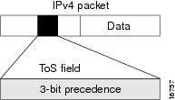
Using the ToS bits, you can define up to eight classes of service. Other features configured throughout the network can then use these bits to determine how to treat the packet in regard to the ToS to grant it. These other QoS features can assign appropriate traffic-handling policies, including congestion management strategy and bandwidth allocation. For example, although IP precedence is not a queuing feature, queuing features, such as LLQ, can use the IP precedence setting of the packet to prioritize traffic.
By setting precedence levels on incoming traffic and using them in combination with the Cisco IOS XR QoS queuing features, you can create differentiated service.
So that each subsequent network element can provide service based on the determined policy, IP precedence is usually deployed as close to the edge of the network or administrative domain as possible. You can think of IP precedence as an edge function that allows core, or backbone, QoS features, such as WRED, to forward traffic based on CoS. IP precedence can also be set in the host or network client, but this setting can be overridden by policy within the network.
The configuration task is described in the “Configuring Class-based Unconditional Packet Marking” section on page 46.
IP Precedence Bits Used to Classify Packets
Use the three IP precedence bits in the ToS field of the IP header to specify the CoS assignment for each packet. As mentioned earlier, you can partition traffic into a maximum of eight classes and then use policy maps to define network policies in terms of congestion handling and bandwidth allocation for each class.
For historical reasons, each precedence corresponds to a name. These names are defined in RFC 791. This table lists the numbers and their corresponding names, from least to most important.
The IP precedence feature allows you considerable flexibility for precedence assignment. That is, you can define your own classification mechanism. For example, you might want to assign precedence based on application or access router.
Note | IP precedence bit settings 6 and 7 are reserved for network control information, such as routing updates. |
IP Precedence Value Settings
By default, Cisco IOS XR software leaves the IP precedence value untouched. This preserves the precedence value set in the header and allows all internal network devices to provide service based on the IP precedence setting. This policy follows the standard approach stipulating that network traffic should be sorted into various types of service at the edge of the network and that those types of service should be implemented in the core of the network. Routers in the core of the network can then use the precedence bits to determine the order of transmission, the likelihood of packet drop, and so on.
Because traffic coming into your network can have the precedence set by outside devices, we recommend that you reset the precedence for all traffic entering your network. By controlling IP precedence settings, you prohibit users that have already set the IP precedence from acquiring better service for their traffic simply by setting a high precedence for all of their packets.
The class-based unconditional packet marking, LLQ, and WRED features can use the IP precedence bits.
You can use these features to set the IP precedence in packets:
-
Class-based unconditional packet marking. See Configuring Class-based Unconditional Packet Marking, page 46.
-
QoS Policy Propagation Using Border Gateway Protocol (QPPB). See QoS Policy Propagation Using Border Gateway Protocol, page 25.
IP Precedence Compared to IP DSCP Marking
IP precedence and DSCP markings are used to decide how packets should be treated in WRED.
The IP DSCP value is the first six bits in the ToS byte, and the IP precedence value is the first three bits in the ToS byte. The IP precedence value is actually part of the IP DSCP value. Therefore, both values cannot be set simultaneously. If both values are set simultaneously, the packet is marked with the IP DSCP value.
If you need to mark packets in your network and all your devices support IP DSCP marking, use the IP DSCP marking to mark your packets because the IP DSCP markings provide more unconditional packet marking options. If marking by IP DSCP is undesirable, however, or if you are unsure if the devices in your network support IP DSCP values, use the IP precedence value to mark your packets. The IP precedence value is likely to be supported by all devices in the network.
You can set up to 8 different IP precedence markings and 64 different IP DSCP markings.
QoS Policy Propagation Using Border Gateway Protocol
Packet classification identifies and marks traffic flows that require congestion management or congestion avoidance on a data path. Quality-of-service Policy Propagation Using Border Gateway Protocol (QPPB) allows you to classify packets by Qos Group ID, based on access lists (ACLs), Border Gateway Protocol (BGP) community lists, BGP autonomous system (AS) paths, Source Prefix address, or Destination Prefix address. After a packet has been classified, you can use other QoS features such as policing and weighted random early detection (WRED) to specify and enforce policies to fit your business model.
QoS Policy Propagation Using BGP (QPPB) allows you to map BGP prefixes and attributes to Cisco Express Forwarding (CEF) parameters that can be used to enforce traffic policing. QPPB allows BGP policy set in one location of the network to be propagated using BGP to other parts of the network, where appropriate QoS policies can be created.
QPPB supports both the IPv4 and IPv6 address-families.
QPPB allows you to classify packets based on:
-
BGP community lists. You can use community lists to create groups of communities to use in a match clause of a route policy. As with access lists, you can create a series of community lists.
-
BGP autonomous system paths. You can filter routing updates by specifying an access list on both incoming and outbound updates, based on the BGP autonomous system path.
-
Source Prefix address. You can classify a set of prefixes coming from the address of a BGP neighbor(s).
-
Destination Prefix address. You can classify a set of BGP prefixes.
Classification can be based on the source or destination address of the traffic. BGP and CEF must be enabled for the QPPB feature to be supported.
QoS on the Satellite System
AutoQoS which automates consistent deployment of QoS features is enabled on the satellite system. All the user-configured Layer2 and Layer3 QoS features are applied on the ASR9000 and no separate Qos configuration required for the satellite system. Auto-Qos handles the over-subscription of the ICL links. All other QoS features, including broadband QoS, on regular ports are supported on satellite ports as well. System congestion handling between the ASR9000 Series Router and satellite ports is setup to maintain priority and protection. AutoQoS Provide sufficient differentiation between different classes of traffic that flow on the satellite ICLs between the ASR9000 Series Router and the Satellite .
The system can support up to 14 unique shape rates for 1G port shapers. 1G ports are represented using a L0 entity in the Traffic Manager (TM) hierarchy. Port shapers are applied at this level. When speed changes on satellite ports, QOS EA would automatically reconfigure any policy-maps based on underlying satellite ports speed. However if there are no policies, then the Policy Manager (PM) needs to setup the speed of the port by calling the port-shaper API (Application Programming Interface). The system shall modify any policies which are percentage-based when the underlying ports speed changes due to AN. There would be a timelag for the Autonegotiated speed to be propagated to the policies on the ASR9000 series router and during that time, packet drops are expected in the satellite device.
For more information about QoS for the satellite system, refer the Cisco IOS XR Modular Quality of Service Configuration Guide for the Cisco XR 12000 Series Router.
ACL Deny
A QOS policy can use a class map which in turn uses access lists (ACLs) to match packets. Unlike interface ACLs, QOS ACLs (as per the MQC specification) ignore permit and deny access control entries (ACEs). The ACL Deny feature allows deny ACEs in ACLs in a class map to be processed as deny actions. If the ACL Deny feature is not configured (the default), any deny ACEs in a class map are rejected and a warning message is displayed to this effect.
The ACL deny feature takes into account the action associated with the access control entry (permit or deny), treating the deny action in an ACL differently from the permit action. The ACE permit and deny actions in an access group within a class map are classified differently. Traffic matching an ACL with a deny action skips the class map and attempts to match subsequent classes. If there is no deny ACE for an ACL, the packet skips to the next class.
Hierarchical Ingress Policing
The Hierarchical Ingress Policing feature is an MQC-based solution that supports hierarchical policing on ingress interfaces. This feature allows enforcement of service level agreements (SLA) while applying the classification sub-model for different QoS classes on the inbound interface. The hierarchical ingress policing provides support at levels:
Hierarchical policing allows policing of individual traffic classes as well as on a collection of traffic classes. This is useful in a situation where you want the collective police rate to be less than the sum of individual police (or maximum) rates.
Hierarchical Policing for Frame Relay on Layer 2 VPN
To support hierarchical policing for Frame Relay on Layer 2 VPN, a policy with matching criteria based on the Frame Relay discard eligibility (DE) bit is attached on the main interface, which in turn produces a match, and applies the action for Layer 2 VPN. The supported hierarchical models are:
The parent policy and child policy are configured with independent policers. The parent policy maintains an aggregate rate per permanent virtual circuit (PVC) of the Frame Relay subinterface. The child policy contains the match criteria based on the Frame Relay discard eligibility (DE) bit and a class default.
Note | In the parent hierarchical policer, only a class default is supported. For the class default, the Frame Relay discard eligibility (DE) bit is set to zero. |
Hierarchical Policing for ATM on Layer 2 VPN
A two-level hierarchical policy map is supported in the ingress direction to support policing of the VBR.2 and VBR.3 type of traffic. The parent policy contains the policing configuration for the peak cell rate (PCR) bucket matching on all traffic (excluding OAM traffic). The child policy contains the policing configuration for the sustainable cell rate (SCR) bucket, and typically matches on the CLP0 cells.
The marking actions are supported in the child policy; whereas the policing actions are allowed in the parent policy.
Enhanced Hierarchical Ingress Policing
In hierarchical ingress policing, traffic is policed first at the child policer level and then at the parent policer level. It is possible for traffic that conforms to the maximum rate specified by the child policer to be dropped by the parent policer. This can occur when an exceed action in the child policer is an action other than to drop ingress traffic.
In Enhanced Hierarchical Ingress Policing, the child-conform-aware command prevents the parent policer from dropping any ingress traffic that conforms to the maximum rate specified in the child policer.
Three-Level Hierarchical Policy Maps
The three-level hierarchical policy map feature supports three levels of hierarchy in the egress direction. These levels are:
Using three levels allows classification of traffic going into the priority queue and the policing of the classified traffic streams at different rates. This means that the queue properties such as bandwidth, bandwidth remaining, shape, priority, random detect, and queue-limit still apply for all of the traffic streams together.
Ingress Queuing Support
Ingress queuing is disabled for some line cards.
The tables below list out the ingress queuing support for fixed port and modular line cards.
Note | Ingress queuing is not supported on ASR9K-SIP-700 line cards. |
Fixed port Line Card
| LC type | Ingress Queuing Support |
|---|---|
|
A9K-24x10GE-SE |
Yes |
|
A9K-24x10GE-TR |
Yes |
|
A9K-36x10GE-SE |
No |
|
A9K-36x10GE-TR |
No |
|
A9K-2x100GE-SE |
No |
|
A9K-2x100GE-TR |
No |
|
A9K-1x100GE-SE |
No |
|
A9K-1x100GE-TR |
No |
Modular Line Card
| LC type | EP type | Ingress Queuing Support |
|---|---|---|
|
A9K-MOD80-SE |
A9K-MPA-20X1GE |
Yes |
|
A9K-MOD80-SE |
A9K-MPA-4X10GE |
No |
|
A9K-MOD80-SE |
A9K-MPA-2X10GE |
Yes |
|
A9K-MOD80-SE |
A9K-MPA-1X40GE |
No |
|
A9K-MOD80-TR |
A9K-MPA-20X1GE |
Yes |
|
A9K-MOD80-TR |
A9K-MPA-4X10GE |
No |
|
A9K-MOD80-TR |
A9K-MPA-2X10GE |
Yes |
|
A9K-MOD80-TR |
A9K-MPA-1X40GE |
No |
|
A9K-MOD160-SE |
A9K-MPA-20X1GE |
Yes |
|
A9K-MOD160-SE |
A9K-MPA-4X10GE |
Yes |
|
A9K-MOD160-SE |
A9K-MPA-2X10GE |
Yes |
|
A9K-MOD160-SE |
A9K-MPA-1X40GE |
No |
|
A9K-MOD160-SE |
A9K-MPA-2X40GE |
No |
|
A9K-MOD160-SE |
A9K-MPA-8X10GE |
No |
|
A9K-MOD160-TR |
A9K-MPA-20X1GE |
Yes |
|
A9K-MOD160-TR |
A9K-MPA-4X10GE |
Yes |
|
A9K-MOD160-TR |
A9K-MPA-2X10GE |
Yes |
|
A9K-MOD160-TR |
A9K-MPA-1X40GE |
No |
|
A9K-MOD160-TR |
A9K-MPA-2X40GE |
No |
|
A9K-MOD160-TR |
A9K-MPA-8X10GE |
No |
|
ASR9001-LC |
Chassis fixed 4X10GE |
No |
|
ASR9001-LC |
A9K-MPA-4X10GE |
No |
|
ASR9001-LC |
A9K-MPA-2X10GE |
No |
|
ASR9001-LC |
A9K-MPA-1X40GE |
No |
|
ASR9001-LC |
A9K-MPA-20X1GE |
No |
In-Place Policy Modification
The In-Place Policy Modification feature allows you to modify a QoS policy even when the QoS policy is attached to one or more interfaces. When you modify the QoS policy attached to one or more interfaces, the QoS policy is automatically modified on all the interfaces to which the QoS policy is attached. A modified policy is subject to the same checks that a new policy is subject to when it is bound to an interface
However, if the policy modification fails on any one of the interfaces, an automatic rollback is initiated to ensure that the earlier policy is effective on all the interfaces. After successfully modifying a policy, the modifications take effect on all the interfaces to which the policy is attached.
The configuration session is blocked until the policy modification is successful on all the relevant interfaces. In case of a policy modification failure, the configuration session is blocked until the rollback is completed on all relevant interfaces.
Note | You cannot resume the configuration on the routers until the configuration session is unblocked. |
When a QoS policy attached to an interface is modified, QoS is first disabled on the interface, hardware is reprogrammed for the modified policy, and QoS is reenabled on the interface. For a short period of time, no QoS policy is active on the interface. In addition, the QoS statistics for the policy that is attached to an interface is lost (reset to 0) when the policy is modified.
Recommendations for Using In-Place Policy Modification
For a short period of time while a QoS policy is being modified, no QoS policy is active on the interface. In the unlikely event that the QoS policy modification and rollback both fail, the interface is left without a QoS policy.
For these reasons, it is best to modify QoS policies that affect the fewest number of interfaces at a time. Use the show policy-map targets command to identify the number of interfaces that will be affected during policy map modification.
Dynamic Modification of Interface Bandwidth
This section describes the dynamic modification of interface bandwidth feature.
Policy States
How to Configure Modular QoS Packet Classification
Creating a Traffic Class
Note | Users can provide multiple values for a match type in a single line of configuration; that is, if the first value does not meet the match criteria, then the next value indicated in the match statement is considered for classification. |
For conceptual information, see the Traffic Class Elements, page 16.
- All match commands specified in this configuration task are considered optional, but you must configure at least one match criterion for a class.
-
For the match access-group command, QoS classification based on the packet length or TTL (time to live) field in the IPv4 and IPv6 headers is not supported.
-
For the match access-group command, when an ACL list is used within a class-map, the deny action of the ACL is ignored and the traffic is classified based on the specified ACL match parameters.
-
The match discard-class command is not supported on the Asynchronous Transfer Mode (ATM) interfaces.
1.
configure
2.
class-map [type qos]
[match-any]
[match-all]
class-map-name
3.
match [not]
access-group [ipv4| ipv6]
access-group-name
4.
match
[not] cos
[cos-value] [cos-value0 ... cos-value7]
5. match [not] cos inner [inner-cos-value] [inner-cos-value0...inner-cos-value7]
6.
match
destination-address mac
destination-mac-address
7.
match
source-address
mac
source-mac-address
8. match [not] discard-class discard-class-value [discard-class-value1 ... discard-class-value6]
9. match [not] dscp [ipv4 | ipv6] dscp-value [dscp-value ... dscp-value]
10.
match [not]
mpls experimental
topmost
exp-value [exp-value1 ...
exp-value7]
11.
match
[not] precedence [ipv4 |
ipv6]
precedence-value
[precedence-value1 ...
precedence-value6]
12. match [not] protocol protocol-value [protocol-value1 ... protocol-value7]
13. match [not] qos-group [qos-group-value1 ... qos-group-value8]
14. match vlan [inner] vlanid [vlanid1 ... vlanid7]
15.
commit
DETAILED STEPS
Creating a Traffic Policy
To create a traffic policy, use the policy-map command to specify the traffic policy name.
The traffic class is associated with the traffic policy when the class command is used. The class command must be issued after you enter the policy map configuration mode. After entering the class command, the router is automatically in policy map class configuration mode, which is where the QoS policies for the traffic policy are defined.
These class-actions are supported:
-
bandwidth—Configures the bandwidth for the class. See the Configuring Modular Quality of Service Congestion Management on Cisco IOS XR Software module.
-
police—Police traffic. See the Configuring Modular Quality of Service Congestion Management on Cisco IOS XR Software module.
-
priority—Assigns priority to the class. See the Configuring Modular Quality of Service Congestion Management on Cisco IOS XR Software module.
-
queue-limit—Configures queue-limit (tail drop threshold) for the class. See the Configuring Modular Quality of Service Congestion Management on Cisco IOS XR Software module.
-
random-detect—Enables Random Early Detection. See the Configuring Modular Quality of Service Congestion Management on Cisco IOS XR Software module.
-
set—Configures marking for this class. See the Class-based Unconditional Packet Marking Feature and Benefits, page 20.
-
shape—Configures shaping for the class. See the Configuring Modular Quality of Service Congestion Management on Cisco IOS XR Software module.
For additional commands that can be entered as match criteria, see the Cisco IOS XR Modular Quality of Service Command Reference for the Cisco XR 12000 Series Router.
For conceptual information, see Traffic Policy Elements, page 17.
1.
configure
2.
policy-map [
type
qos ] policy-name
4.
set precedence
[
tunnel ] precedence-value
5.
commit
DETAILED STEPS
Attaching a Traffic Policy to an Interface
After the traffic class and traffic policy are created, you must use the service-policy interface configuration command to attach a traffic policy to an interface, and to specify the direction in which the policy should be applied (either on packets coming into the interface or packets leaving the interface).
For additional commands that can be entered in policy map class configuration mode, see the Cisco IOS XR Modular Quality of Service Command Referencefor the Cisco XR 12000 Series Router.
A traffic class and traffic policy must be created before attaching a traffic policy to an interface.
1.
configure
2.
interface
type
interface-path-id
3.
service-policy {input
|
output}
policy-map
4.
commit
5.
show policy-map
interface
type
interface-path-id [input |
output]
DETAILED STEPS
| Command or Action | Purpose | |
|---|---|---|
| Step 1 |
configure
| |
| Step 2 | interface
type
interface-path-id
Example: RP/0/0/CPU0:router(config)# interface gigabitethernet 0/1/0/9 |
Configures an interface and enters the interface configuration mode. |
| Step 3 | service-policy {input
|
output}
policy-map
Example: RP/0/0/CPU0:router(config-if)# service-policy output policy1 |
Attaches a policy map to an input or output interface to be used as the service policy for that interface. In this example, the traffic policy evaluates all traffic leaving that interface. |
| Step 4 |
commit
| |
| Step 5 | show policy-map
interface
type
interface-path-id [input |
output]
Example: RP/0/0/CPU0:router# show policy-map interface gigabitethernet 0/1/0/9 |
(Optional) Displays statistics for the policy on the specified interface. |
Attaching a Shared Policy Instance to Multiple Subinterfaces
After the traffic class and traffic policy are created, you can optionally use the service-policy (interface) configuration command to attach a shared policy instance to multiple subinterfaces, and to specify the direction in which the policy should be applied (either on packets coming into or leaving the subinterface).
Note | A shared policy can include a combination of Layer 2 and Layer 3 subinterfaces. |
For additional commands that can be entered in policy map class configuration mode, see the Cisco ASR 9000 Series Aggregation Services Routers Modular Quality of Service Command Reference.
A traffic class and traffic policy must be created before attaching a shared policy instance to a subinterface.
Shared policy instance across multiple physical interfaces is not supported.
1.
configure
2.
interface type interface-path-id
3. service-policy {input | output} policy-map [shared-policy-instance instance-name]
4.
commit
5.
show policy-map shared-policy-instance instance-name [input | output] location rack/slot/module
DETAILED STEPS
| Command or Action | Purpose | |
|---|---|---|
| Step 1 |
configure
| |
| Step 2 | interface type interface-path-id Example: RP/0/RSP0/CPU0:router(config)# interface gigabitethernet 0/1/0/0.1 | Enters interface configuration mode and configures a subinterface. |
| Step 3 | service-policy {input | output} policy-map [shared-policy-instance instance-name] Example: RP/0/RSP0/CPU0:router(config-if)# service-policy output policy1 shared-policy-instance Customer1 | Attaches a policy map to an input or output subinterface to be used as the service policy for that subinterface. |
| Step 4 |
commit
| |
| Step 5 | show policy-map shared-policy-instance instance-name [input | output] location rack/slot/module Example: RP/0/RSP0/CPU0:router# show policy-map shared-policy-instance Customer1 location 0/1/0/7.1 | (Optional) Displays statistics for the policy on the specified shared policy instance subinterface. |
Attaching a Shared Policy Instance to Bundle Interfaces or EFP Bundles
After the traffic class and traffic policy are created, you can optionally use the service-policy (interface) configuration command to attach a shared policy instance to bundle interfaces and to bundle EFPs, and to specify the direction in which the policy should be applied (either on packets coming into or leaving the subinterface).
For additional commands that can be entered in policy map class configuration mode, see the Cisco ASR 9000 Series Aggregation Services Router Modular Quality of Service Command Reference.
A traffic class and traffic policy must be created before attaching a shared policy instance to bundle interfaces or EFP bundles.
Shared policy instance across multiple physical interfaces is not supported.
1.
configure
2.
interface Bundle-Ether bundle-id
3. service-policy {input | output} policy-map [shared-policy-instance instance-name]
4.
commit
5.
show policy-map shared-policy-instance instance-name [input | output] location location-id
DETAILED STEPS
| Command or Action | Purpose | |
|---|---|---|
| Step 1 |
configure
| |
| Step 2 | interface Bundle-Ether bundle-id Example: RP/0/RP1/CPU0:router(config)# interface Bundle-Ether 100.1 l2transport | Enters interface configuration mode and configures a bundle interface. |
| Step 3 | service-policy {input | output} policy-map [shared-policy-instance instance-name] Example: RP/0/RSP0/CPU0:router(config-if)# service-policy output policy1 shared-policy-instance Customer1 | Attaches a policy map to an input or output bundle interface to be used as the service policy for that subinterface. |
| Step 4 |
commit
| |
| Step 5 | show policy-map shared-policy-instance instance-name [input | output] location location-id Example: RP/0/RSP0/CPU0:router# show policy-map shared-policy-instance Customer1 location 0/rsp0/cpu0 | (Optional) Displays statistics for the policy at the specified shared policy instance location. |
Configuring Class-based Unconditional Packet Marking
This configuration task explains how to configure the following class-based, unconditional packet marking features on your router:
Note | IPv4 and IPv6 QoS actions applied to MPLS tagged packets are not supported. The configuration is accepted, but no action is taken. |
1.
configure
4.
set
precedence
[tunnel]
number
6.
set
qos-group
qos-group-value
9.
set mpls experimental
{imposition |
topmost}
exp-value
10.
set srp-priority
priority-value
11.
set
discard-class
discard-class-value
13.
exit
15. interface type interface-path-id
16.
service-policy {input |
output]}
policy-map
17.
commit
18. show policy-map interface type interface-path-id [input | output]
DETAILED STEPS
| Command or Action | Purpose | |||
|---|---|---|---|---|
| Step 1 |
configure
| |||
| Step 2 | policy-map
policy-name
Example: RP/0/0/CPU0:router(config)# policy-map policy1 |
Creates or modifies a policy map that can be attached to one or more interfaces to specify a service policy and enters the policy map configuration mode. | ||
| Step 3 | class
class-name
Example: RP/0/0/CPU0:router(config-pmap)# class class1 |
Specifies the name of the class whose policy you want to create or change and enters the policy class map configuration mode. | ||
| Step 4 | set
precedence
[tunnel]
number
Example: RP/0/0/CPU0:router(config-pmap-c)# set precedence 1 | |||
| Step 5 | set dscp
[tunnel]
number
Example: RP/0/0/CPU0:router(config-pmap-c)# set dscp 5 | |||
| Step 6 | set
qos-group
qos-group-value
Example: RP/0/0/CPU0:router(config-pmap-c)# set qos-group 31 |
Sets the QoS group identifiers on IPv4 or MPLS packets. The set qos-group command is supported only on an ingress policy. | ||
| Step 7 | set cos
cos-value
Example: RP/0/0/CPU0:router(config-pmap-c)# set cos 7 |
Sets the specific IEEE 802.1Q Layer 2 CoS value of an outgoing packet. Values are from 0 to7. | ||
| Step 8 | set cos
[inner]
cos-value
Example: RP/0/0/CPU0:router(config-pmap-c)# set cos 7 |
Sets the specific IEEE 802.1Q Layer 2 CoS value of an outgoing packet. Values are from 0 to7. Sets the Layer 2 CoS value of an outgoing packet.
| ||
| Step 9 | set mpls experimental
{imposition |
topmost}
exp-value
Example: RP/0/0/CPU0:router(config-pmap-c)# set mpls experimental imposition 3 |
Sets the experimental value of the MPLS packet top-most or imposition labels.
| ||
| Step 10 | set srp-priority
priority-value
Example: RP/0/0/CPU0:router(config-pmap-c)# set srp-priority 3 |
Sets the spatial reuse protocol (SRP) priority value of an outgoing packet.
| ||
| Step 11 | set
discard-class
discard-class-value
Example: RP/0/0/CPU0:router(config-pmap-c)# set discard-class 3 |
Sets the discard class on IP Version 4 (IPv4) or Multiprotocol Label Switching (MPLS) packets.
| ||
| Step 12 | set atm-clp
Example: RP/0/0/CPU0:router(config-pmap-c)# set atm-clp | |||
| Step 13 | exit
Example:
RP/0/0/CPU0:router(config-pmap-c)# exit
|
Returns the router to policy map configuration mode. | ||
| Step 14 | exit
Example: RP/0/0/CPU0:router(config-pmap)# exit | |||
| Step 15 | interface
type
interface-path-id
Example: RP/0/0/CPU0:router(config)# interface pos 0/2/0/0 |
Configures an interface and enters the interface configuration mode. | ||
| Step 16 | service-policy {input |
output]}
policy-map
Example: RP/0/0/CPU0:router(config-if)# service-policy output policy1 |
Attaches a policy map to an input or output interface to be used as the service policy for that interface. In this example, the traffic policy evaluates all traffic leaving that interface. | ||
| Step 17 |
commit
| |||
| Step 18 | show policy-map
interface
type
interface-path-id
[input |
output]
Example: RP/0/0/CPU0:router# show policy-map interface pos 0/2/0/0 |
(Optional) Displays policy configuration information for all classes configured for all service policies on the specified interface. |
Configuring QoS Policy Propagation Using Border Gateway Protocol
This section explains how to configure Policy Propagation Using Border Gateway Protocol (BGP) on a router based on BGP community lists, BGP autonomous system paths, access lists, source prefix address, or destination prefix address.
Policy Propagation Using BGP Configuration Task List
Policy propagation using BGP allows you to classify packets by IP precedence and/or QoS group ID, based on BGP community lists, BGP autonomous system paths, access lists, source prefix address and destination prefix address. After a packet has been classified, you can use other quality-of-service features such as weighted random early detection (WRED) to specify and enforce policies to fit your business model.
Overview of Tasks
To configure Policy Propagation Using BGP, perform these basic tasks:
-
Configure BGP and Cisco Express Forwarding (CEF). To configure BGP, see Cisco IOS XR Routing Configuration Guide . To configure CEF, see Cisco IOS XR IP Address and Services Configuration Guide .
-
Define the route policy. Set the IP precedence and/or QoS group ID, based on the BGP community list, BGP autonomous system path, access list, source prefix address or destination prefix address.
-
Configure and enable a QoS Policy to use the above classification (IP precedence or QoS group ID). To configure committed access rate (CAR), WRED and tail drop, see the Configuring Modular QoS Congestion Avoidance on Cisco IOS XR Software module.
Defining the Route Policy
This task defines the route policy used to classify BGP prefixes with IP precedence or QoS group ID.
Prerequisites
Configure the BGP community list, or access list, for use in the route policy.
DETAILED STEPS
| Command or Action | Purpose | |
|---|---|---|
| Step 1 |
configure
| |
| Step 2 | route-policy
name
Example: RP/0/0/CPU0:router(config)# route-policy r1 |
Enters route policy configuration mode and specifies the name of the route policy to be configured. |
| Step 3 |
set
qos-group qos-group-value
Example: RP/0/0/CPU0:router(config-pmap-c)# set qos-group 30
|
Sets the QoS group identifiers. The set qos-group command is supported only on an ingress policy. |
| Step 4 |
commit
|
Applying the Route Policy to BGP
This task applies the route policy to BGP.
Prerequisites
Configure BGP and CEF.
1.
configure
2.
router bgp
as-number
3.
address-family
{ ipv4
|ipv6}
address-family-modifier
4.
table-policy
policy-name
5.
commit
DETAILED STEPS
| Command or Action | Purpose | |
|---|---|---|
| Step 1 |
configure
| |
| Step 2 |
router bgp
as-number
Example: RP/0/0/CPU0:router(config)# router bgp 120
|
Enters BGP configuration mode. |
| Step 3 |
address-family
{ ipv4
|ipv6}
address-family-modifier
Example: RP/0/0/CPU0:router(config-bgp)# address-family ipv4 unicast
|
Enters address-family configuration mode, allowing you to configure an address family. |
| Step 4 |
table-policy
policy-name
Example: RP/0/0/CPU0:router(config-bgp-af) # table-policy qppb a1
|
Configures the routing policy for installation of routes to RIB. |
| Step 5 |
commit
|
Configuring QPPB on the Desired Interfaces
This task applies QPPB to a specified interface. The traffic begins to be classified, based on matching prefixes in the route policy. The source or destination IP address of the traffic can be used to match the route policy.
1.
configure
2.
interface
type
interface-path-id
3.
ipv4 | ipv6
bgp policy
propagation input{ip-precedence|qos-group} {destination[ip-precedence
{destination|source}] {source[ip-precedence
{destination|source}]
4.
commit
DETAILED STEPS
| Command or Action | Purpose | |
|---|---|---|
| Step 1 |
configure
| |
| Step 2 | interface
type
interface-path-id
Example: RP/0/0/CPU0:router(config)# interface pos 0/2/0/0 |
Enters interface configuration mode and associates one or more interfaces to the VRF. |
| Step 3 | ipv4 | ipv6
bgp policy
propagation input{ip-precedence|qos-group} {destination[ip-precedence
{destination|source}] {source[ip-precedence
{destination|source}]
Example:
RP/0/0/CPU0:router(config-if)# ipv4 bgp policy propagation input qos-group destination
|
Enables QPPB on an interface |
| Step 4 |
commit
|
QPPB Scenario
Consider a scenario where in traffic is moving from Network1 to Network2 through (a single) router port1 and port2. If QPPB is enabled on port1, then
Configuring ACL Deny
ACL deny allows traffic matching an ACL with a deny access control entry (ACE) to skip the class map and attempt to match subsequent classes. If there is no deny ACE for the ACL, the ACL Deny feature does not take effect.
The ACL deny feature is disabled by default.
Note | Configuring ACL Deny displays a warning message which mentions that the commit takes effect only after a LC reload. |
DETAILED STEPS
| Command or Action | Purpose | |
|---|---|---|
| Step 1 |
configure
| |
| Step 2 | hw-module qos acl-deny enable location node-id Example: RP/0/0/CPU0:router(config)# hw-module qos acl-deny enable location 0/2/0 | Enables the ACL deny feature for the specified location. When you configure the ACL Deny feature, the following warning message is displayed: The commit will take effect only after a LC reload. |
| Step 3 |
commit
|
Configuring Hierarchical Ingress Policing
The hierarchical ingress policing is supported at two levels:
The Modular QoS command-line interface (MQC) provides hierarchical configuration, with the following limitations:
-
The parent level consists of class defaults or class maps that match VLAN (in the case of nCmD policy).
-
The only allowed action on the parent class is to police without set actions.
-
The child level consists of a flat policy that can be configured with the supported action or the class-map command.
-
The parent policer value is used as a reference bandwidth for the child policy whenever required.
DETAILED STEPS
| Command or Action | Purpose | |
|---|---|---|
| Step 1 |
configure
| |
| Step 2 | policy-map
policy-name
Example: RP/0/0/CPU0:router(config)# policy-map parent |
Creates or modifies a policy map that can be attached to one or more interfaces to specify a service policy and enters the policy map configuration mode. |
| Step 3 | class
class-name
Example: RP/0/0/CPU0:router(config-pmap)# class class-default |
Specifies the name of the class whose policy you want to create or change and enters the policy map class configuration mode. |
| Step 4 |
service-policy
policy-name
Example: RP/0/0/CPU0:router(config-pmap-c)# service-policy child |
Specifies the service-policy as a QoS policy within a policy map. |
| Step 5 | police rate
percent
percentage
Example: RP/0/0/CPU0:router(config-pmap-c)# police rate percent 50 |
Configures traffic policing and enters policy map police configuration mode. |
| Step 6 | conform-action
action
Example: RP/0/0/CPU0:router(config-pmap-c-police)# conform-action transmit |
Configures the action to take on packets that conform to the rate limit. The allowed action is transmit that transmits the packets. |
| Step 7 | exceed-action
action
Example: RP/0/0/CPU0:router(config-pmap-c-police)# exceed-action drop |
Configures the action to take on packets that exceed the rate limit. The allowed action is drop that drops the packet. |
| Step 8 |
commit
|
Configuring Enhanced Hierarchical Ingress Policing
The difference between configuring enhanced hierarchical ingress policing and configuring hierarchical ingress policing is the addition of the child-conform-aware command.
When used in the parent policer, the child-conform-aware command prevents the parent policer from dropping any ingress traffic that conforms to the maximum rate specified in the child policer.
The Modular QoS command-line interface (MQC) provides enhanced hierarchical ingress policing configuration, with the following limitations:
Supported on 10 Gbps IP Services Engine (Engine 5) line cards
DETAILED STEPS
| Command or Action | Purpose | |
|---|---|---|
| Step 1 |
configure
| |
| Step 2 | policy-map policy-name Example: RP/0/0/CPU0:router(config)# policy-map parent | Enters policy map configuration mode. Creates or modifies a policy map that can be attached to one or more interfaces to specify a service policy. |
| Step 3 | class class-name Example: RP/0/0/CPU0:router(config-pmap)# class class-default | Enters policy map class configuration mode. Specifies the name of the class whose policy you want to create or change. |
| Step 4 | service-policy policy-name Example: RP/0/0/CPU0:router(config-pmap-c)# service-policy child | |
| Step 5 | police rate percent percentage Example: RP/0/0/CPU0:router(config-pmap-c)# police rate percent 50 | Configures traffic policing and enters policy map police configuration mode. |
| Step 6 | child-conform-aware Example: RP/0/0/CPU0:router(config-pmap-c-police)# child-conform-aware | Prevents the parent policer from dropping any ingress traffic that conforms to the maximum rate specified in a child policer. |
| Step 7 | conform-action action Example: RP/0/0/CPU0:router(config-pmap-c-police)# conform-action transmit | Configures the action to take on packets that conform to the rate limit. The allowed action is: |
| Step 8 | exceed-action action Example: RP/0/0/CPU0:router(config-pmap-c-police)# exceed-action drop | Configures the action to take on packets that exceed the rate limit. The allowed action is: |
| Step 9 | end
or
commit Example: RP/0/0/CPU0:router(config-pmap-c-police)# end RP/0/0/CPU0:router(config-pmap-c-police)# commit |
|
Configuring a Three-Level Hierarchical Policy
Matching the Frame Relay DE Bit
You can use the match fr-de command to enable frames with a DE bit setting of 1 to be considered a member of a defined class and forwarded according to the specifications set in the service policy.
DETAILED STEPS
| Command or Action | Purpose | |
|---|---|---|
| Step 1 | configure Example: RP/0/0/CPU0:router# configure | |
| Step 2 | class-map class-name Example: RP/0/0/CPU0:router(config)# class-map c1 | Enters class map configuration mode. Creates a class map to be used for matching packets to the class whose name you specify. |
| Step 3 | match fr-de Example: RP/0/0/CPU0:router(config-cmap)# match fr-de | Sets the Frame Relay DE bit setting for all packets that match the specified traffic class. The Frame Relay DE bit value can be 0 or 1. |
| Step 4 | exit Example: RP/0/0/CPU0:router(config-cmap)# exit |
Matching the ATM CLP Bit
You can use the match atm clp command to enable packet matching on the basis of the ATM cell loss priority (CLP).
DETAILED STEPS
| Command or Action | Purpose | |
|---|---|---|
| Step 1 | configure Example: RP/0/0/CPU0:router# configure | |
| Step 2 | class-map class-name Example: RP/0/0/CPU0:router(config)# class-map c1 | Enters class map configuration mode. Creates a class map to be used for matching packets to the class whose name you specify. |
| Step 3 | match atm clp Example: RP/0/0/CPU0:router(config-cmap)# match atm clp | Sets the ATM cell loss priority (CLP) bit setting for all packets that match the specified traffic class. The ATM CLP bit value can be 0 or 1. |
| Step 4 | exit Example: RP/0/0/CPU0:router(config-cmap)# exit |
Configuration Examples for Configuring Modular QoS Packet Classification
Traffic Classes Defined: Example
In this example, two traffic classes are created and their match criteria are defined. For the first traffic class called class1, ACL 101 is used as the match criterion. For the second traffic class called class2, ACL 102 is used as the match criterion. Packets are checked against the contents of these ACLs to determine if they belong to the class.
class-map class1
  match access-group ipv4 101
  exit
!
class-map class2
  match access-group ipv4 102
  exit
Traffic Policy Created: Example
In this example, a traffic policy called policy1 is defined to contain policy specifications for the two classes—class1 and class2. The match criteria for these classes were defined in the traffic classes created in the “Traffic Classes Defined: Example” section on page 68.
For class1, the policy includes a bandwidth allocation request and a maximum packet limit for the queue reserved for the class. For class2, the policy specifies only a bandwidth allocation request.
Traffic Policy Attached to an Interface: Example
This example shows how to attach an existing traffic policy to an interface (see the Traffic Classes Defined: Example, page 68). After you define a traffic policy with the policy-map command, you can attach it to one or more interfaces to specify the traffic policy for those interfaces by using the service-policy command in interface configuration mode. Although you can assign the same traffic policy to multiple interfaces, each interface can have only one traffic policy attached at the input and only one traffic policy attached at the output.
interface pos 0/1/0/0
  service-policy output policy1
  exit
!
EFP Load Balancing with Shared Policy Instance: Example
The following examples show how to configure load balancing of an EFP when SPI is implemented. For additional information on EFP load balancing on link bundles, see the Cisco IOS XR Interface and Hardware Component Configuration Guide.
- Configuring a Bundle Interface: Example
- Configuring Two Bundle EFPs with the Load Balance Options: Example
Configuring a Bundle Interface: Example
interface Bundle-Ether 50
interface gigabitethernet 0/1/0/5
  bundle id 50 mode active
interface gigabitethernet 0/1/0/8
  bundle id 50 mode active
Configuring Two Bundle EFPs with the Load Balance Options: Example
This example configures the traffic for two bundle EFPs go over the same physical member link.
interface Bundle-Ether 50.25 l2transport
  encapsulation dot1q 25
  bundle load-balance hash-select 2
!
interface Bundle-Ether 50.36 l2transport
  encapsulation dot1q 36
  bundle load-balance hash-select 2
Default Traffic Class Configuration: Example
This example shows how to configure a traffic policy for the default class of the traffic policy called policy1. The default class is named class-default, consists of all other traffic, and is being shaped at 60 percent of the interface bandwidth.
policy-map policy1
  class class-default
    shape average percent 60
class-map match-any Command Configuration: Example
This example illustrates how packets are evaluated when multiple match criteria exist. Only one match criterion must be met for the packet in the class-map match-any command to be classified as a member of the traffic class (a logical OR operator). In the example, protocol IP OR QoS group 4 OR access group 101 have to be successful match criteria:
class-map match-any class1
  match protocol ipv4
  match qos-group 4
  match access-group ipv4 101
In the traffic class called class1, the match criteria are evaluated consecutively until a successful match criterion is located. The packet is first evaluated to determine whether IPv4 protocol can be used as a match criterion. If IPv4 protocol can be used as a match criterion, the packet is matched to traffic class class1. If IP protocol is not a successful match criterion, then QoS group 4 is evaluated as a match criterion. Each matching criterion is evaluated to see if the packet matches that criterion. Once a successful match occurs, the packet is classified as a member of traffic class class1. If the packet matches at least one of the specified criteria, the packet is classified as a member of the traffic class.
Note | The match qos-group command is supported only on an egress policy and on an ingress policy for QoS Policy Propagation using BGP (QPPB)-based policies. |
Traffic Policy as a QoS Policy (Hierarchical Traffic Policies) Configuration: Examples
A traffic policy can be nested within a QoS policy when the service-policy command is used in policy map class configuration mode. A traffic policy that contains a nested traffic policy is called a hierarchical traffic policy.
Hierarchical traffic policies can be attached to all supported interfaces for this Cisco IOS XR software release, such as the OC-192 and 10-Gigabit Ethernet interfaces.
- Two-Level Hierarchical Traffic Policy Configuration: Example
- Three-Level Hierarchical Traffic Policy Configuration: Example
Two-Level Hierarchical Traffic Policy Configuration: Example
A two-level hierarchical traffic policy contains a child and a parent policy. The child policy is the previously defined traffic policy that is being associated with the new traffic policy through the use of the service-policy command. The new traffic policy using the pre-existing traffic policy is the parent policy. In the example in this section, the traffic policy called child is the child policy, and the traffic policy called parent is the parent policy.
In this example, the child policy is responsible for prioritizing traffic, and the parent policy is responsible for shaping traffic. In this configuration, the parent policy allows packets to be sent from the interface, and the child policy determines the order in which the packets are sent.
policy-map child
 class mpls
  priority level 1
  police rate 100 mbps burst 10 ms
  !
 !
 class class-default
 !
 end-policy-map
!
policy-map parent
 class class-default
  service-policy child
  shape average 1000 mbps
 !
 end-policy-map
!
Three-Level Hierarchical Traffic Policy Configuration: Example
A three-level hierarchical traffic policy contains a parent, child, and grand-child policy. The first level (parent) policy provides the shaper parameter. The second level (child) policy allows the highest level of complexity and defines queuing and scheduling behavior. The third level (grand-child) policy allows policing and set commands.
In the example, a three-level hierarchical policy is configured.
policy-map parent
  class class-default
    shape average 100 mbps
    service-policy child
!
policy-map child
  class gold
    priority
    service-policy grand-child1
  class silver
    bandwidth 50 mbps
    random detect mpls experimental 4 100 packets 200 packets
    service-policy grand-child2
  class bronze
    bandwidth 10 mbps
    random detect mpls experimental 2 200 packets 400 packets
    service-policy grand-child3
  class class-default
    set mpls experimental topmost 1
!
policy-map grand-child1
  class gold-voice1
    police rate 10 mbps
        conform-action set mpls experimental topmost 5
        exceed-action drop
  class bold-voice2
    police rate 10 mbps
        conform-action set mpls experimental topmost 5
        exceed-action drop
!
policy-map grand-child2
  class silver-data1
    police rate 30 mbps
        conform-action set mpls experimental topmost 3
        exceed-action set mpls experimental topmost 0
  class silver-data2
    police rate 20 mbps
        conform-action set mpls experimental topmost 4
        exceed-action drop
!
policy-map grand-child3
  class bronze-data1
    police rate 40 mbps
    set mpls experimental topmost 2
  class bronze-data2
    set mpls experimental topmost 0
Class-based Unconditional Packet Marking: Examples
These are typical class-based unconditional packet marking examples:
- IP Precedence Marking Configuration: Example
- IP Precedence Tunnel Marking Configuration: Example
- IP DSCP Marking Configuration: Example
- QoS Group Marking Configuration: Example
- Discard Class Marking Configuration: Example
- CoS Marking Configuration: Example
- MPLS Experimental Bit Imposition Marking Configuration: Example
- MPLS Experimental Topmost Marking Configuration: Example
IP Precedence Marking Configuration: Example
In this example, a service policy called policy1 is created. This service policy is associated to a previously defined class map called class1 through the use of the class command, and then the service policy is attached to the output POS interface 0/1/0/0. The IP precedence bit in the ToS byte is set to 1:
policy-map policy1
  class class1
    set precedence 1
!
interface pos 0/1/0/0
  service-policy output policy1
IP Precedence Tunnel Marking Configuration: Example
In the following example, a service policy called policy1 is created. This service policy is associated to a previously defined class map called class1 through the use of the class command, and then the service policy is attached in the input direction on an IPSec interface.The IP precedence value is set to priority (1):
policy-map policy1
  class class1
    set precedence tunnel priority
  !
interface service-ipsec 1
  service-policy output pre-enecrypt policy1
Note | IP precedence tunnel marking is only supported in the outbound pre-encrypt direction. |
Refer to Implementing IPSec Network Security on Cisco IOS XR Software in the Cisco IOS XR System Security Configuration Guide for the Cisco XR 12000 Series Router for more information on configuring IPSec.
IP DSCP Marking Configuration: Example
In this example, a service policy called policy1 is created. This service policy is associated to a previously defined class map through the use of the class command. In this example, it is assumed that a class map called class1 was previously configured and new class map called class2 is created.
In this example, the IP DSCP value in the ToS byte is set to 5:
policy-map policy1
  class class1
    set dscp 5

  class class2
    set dscp ef
After you configure the settings shown for voice packets at the edge, all intermediate routers are configured to provide low-latency treatment to the voice packets, as follows:
class-map voice
  match dscp ef
policy-map qos-policy
  class voice
    priority level 1
    police rate percent 10
The service policy configured in this section is not yet attached to an interface. For information on attaching a service policy to an interface, see the Modular Quality of Service Overview on Cisco IOS XR Software module.
QoS Group Marking Configuration: Example
In this example, a service policy called policy1 is created. This service policy is associated to a class map called class1 through the use of the class command, and then the service policy is attached in the input direction on a GigabitEthernet interface 0/1/0/9. The qos-group value is set to 1.
class-map match-any class1
  match protocol ipv4
  match access-group ipv4 101

policy-map policy1
  class class1
    set qos-group 1
  !
interface GigabitEthernet 0/1/0/9
  service-policy input policy1
Note | The set qos-group command is supported only on an ingress policy. |
Discard Class Marking Configuration: Example
In this example, a service policy called policy1 is created. This service policy is associated to a class map called class1 through the use of the class command, and then the service policy is attached in the input direction on a POS interface 0/1/0/0. The discard-class value is set to 1.
class-map match-any class1
  match protocol ipv4
  match access-group ipv4 101

policy-map policy1
  class class1
    set discard-class 1
  !
interface POS interface 0/1/0/0
  service-policy input policy1
CoS Marking Configuration: Example
In this example, a service policy called policy1 is created. This service policy is associated to a class map called class1 through the use of the class command, and then the service policy is attached in the output direction on a 10-Gigabit Ethernet interface, TenGigE0/1/0/0. The 802.1p (CoS) bits in the Layer 2 header are set to 1.
class-map match-any class1
  match protocol ipv4
  match access-group ipv4 101

policy-map policy1
  class class1
    set cos 1
  !
interface TenGigE0/1/0/0
interface TenGigE0/1/0/0.100
  service-policy output policy1
Note | The set cos command is supported only on egress. |
MPLS Experimental Bit Imposition Marking Configuration: Example
In this example, a service policy called policy1 is created. This service policy is associated to a class map called class1 through the use of the class command, and then the service policy is attached in the input direction on a 10-Gigabit Ethernet interface, TenGigE0/1/0/0. The MPLS EXP bits of all imposed labels are set to 1.
class-map match-any class1
  match protocol ipv4
  match access-group ipv4 101

policy-map policy1
  class class1
    set mpls exp imposition 1
 !
interface TenGigE0/1/0/0
  service-policy input policy1
Note | The set mpls exp imposition command is supported only on an ingress policy. |
MPLS Experimental Topmost Marking Configuration: Example
In this example, a service policy called policy1 is created. This service policy is associated to a class map called class1 through the use of the class command, and then the service policy is attached in the output direction on a 10-Gigabit Ethernet interface, TenGigE0/1/0/0. The MPLS EXP bits on the TOPMOST label are set to 1:
class-map match-any class1
  match mpls exp topmost 2

policy-map policy1
  class class1
    set mpls exp topmost 1
  !
interface TenGigE0/1/0/0
  service-policy output policy1
QoS Policy Propagation using BGP: Examples
These are the IPv4 and IPv6 QPPB examples:
Applying Route Policy: Example
In this example, BGP is being configured for the IPv4 address family:
router bgp 100
 bgp router-id 19.19.19.19
 address-family ipv4 unicast
  table-policy qppbv4_dest
 !
 neighbor 10.10.10.10
  remote-as 8000
  address-family ipv4 unicast
   route-policy pass-all in
   route-policy pass-all out
In this example, BGP is being configured for the IPv6 address family:
router bgp 100
 bgp router-id 19.19.19.19
 address-family ipv6 unicast
  table-policy qppbv6_dest
 !
 neighbor 1906:255::2
  remote-as 8000
  address-family ipv6 unicast
   route-policy pass-all in
   route-policy pass-all out
Applying QPPB on a Specific Interface: Example
This example shows applying QPPBv4 (address-family IPv4) for a desired interface:
config
interface POS0/0/0/0
ipv4 address 10.1.1.1
ipv4 bgp policy propagation input qos-group destination
end
commit
!
This example shows applying QPPBv6 (address-family IPv6) for a desired interface:
config
interface POS0/0/0/0
ipv6 address 1906:255::1/64
ipv6 bgp policy propagation input qos-group destination
end
commit
!
ACL Deny Configuration: Example
The following configuration is an example of the ACL deny feature:
ipv4 access-list acl-permit-deny
  10 permit ipv4 host 10.0.0.0 any
  20 deny ipv4 any any
  !
class-map match-any class-acl-permit-deny
  match access-group ipv4 acl-permit-deny
  !
policy-map pol-acl-permit-deny
  class class-acl-permit-deny
    shape average percent 40
    !
  class class-default
    police rate percent 15
      conform-action transmit
      exceed-action drop
      !
    !
  !
In the example, traffic with the source IP address 10.0.0.0 is classified into the class “class-acl-permit-deny”, but any other IP traffic is expected to match the next class (class-default in this example) because the ACE action is deny for all other IP traffic.
Hierarchical Ingress Policing: Example
This configuration is an example of typical hierarchical ingress policing:
policy-map parent
 class class-default
  service-policy child
  police rate percent 50
  conform-action transmit
  exceed-action drop
This policy map can be applied on any interface or on a subinterface. The incoming traffic on the main interface or subinterface can be IPv4 unicast or multicast, MPLS, or IPv6 unicast or multicast. The child policy map can be a regular policy map that can be configured in the ingress direction on that interface.
If the policy map is applied on a main interface that has subinterfaces, then the configuration is considered as a 1CnD configuration model. Hence, the child policy must be applied on each subinterface and the parent policer polices the aggregate traffic from all subinterfaces.
interface Serial 0/4/1/1/0:0
 encapsulation frame-relay
 service-policy input parent
interface Serial 0/4/1/1/0:0.1 point-to-point

interface Serial 0/4/1/1/0:0.2 point-to-point
In this configuration, the child policy is applied on each of the subinterfaces and the aggregate traffic from all subinterfaces is subjected to the parent policer. In this model, the child policy is not permitted any queuing actions.
An example of the configuration for a nCmD model is as follows:
class-map match-any customera
 match vlan 1-3
class-map match-any customerb
 match vlan 4-7
policy-map parent
 class customera
  service-policy childa
  police rate percent 50
  conform-action transmit
  exceed-action drop
!
 class customerb
  service-policy childb
  police rate percent 70
  conform-action transmit
  exceed-action drop
!
Similar to the 1CnD model, the aggregate traffic from all subinterfaces that match each parent class map is subjected to the parent policer configured in that class map. Also, the child policy is not permitted any queuing actions.
Enhanced Hierarchical Ingress Policing: Example
This example shows parent and child policy maps in which two classes are defined in the child policy. In class AF1, the exceed action is set to an action other than to drop traffic.
If the child-conform-aware command were not configured in the parent policy, the parent policer would drop traffic that matches the conform rate of the child policer but exceeds the conform rate of the parent policer.
When used in the parent policer, the child-conform-aware command prevents the parent policer from dropping any ingress traffic that conforms to the maximum rate specified in the child policer.
policy-map parent
  class class-default
    service-policy child
    police rate percent 50
      child-conform-aware
      conform-action transmit
      exceed-action drop

policy-map child
  class EF
    police rate 1 mbps
      conform-action set mpls experimental imposition 4
      exceed-action drop
  class AF1
    police rate percent 50
      conform-action set mpls experimental imposition 3
      exceed-action set mpls experimental imposition 2
The police rate command allows you to police traffic to control the maximum rate of traffic sent or received on an interface. In the parent policy, the police rate percentage is a percentage of the interface rate. In the child policy, the police rate percentage is a percentage of the parent policer rate.
In this example, the parent policy configures a police rate of 50 percent, which is 50 percent of the maximum bandwidth allowed on the interface. Class AF1 in the child policy configures a police rate of 50 percent, which is 50 percent of the bandwidth allowed in the parent, in this case 25 percent of the maximum bandwidth allowed on the interface.
In-Place Policy Modification: Example
This configuration is an example of in-place policy modification:
configure
policy-map policy1
class class1
set precedence 3
commit
Attaching the policy map to an interface:
configure
interface POS 0/6/0/1
service-policy output policy1
commit
configure
policy-map policy1
class class1
set precedence 5
commit
Note | The modified policy policy1 takes effect on all the interfaces to which the policy is attached. Also, you can modify any class-map used in the policy-map. The changes made to the class-map takes effect on all the interfaces to which the policy is attached. |
Setting the Frame Relay Discard Eligibility Bit: Example
The following example shows how to set the DE bit using the set fr-de command in the traffic policy:
class-map ip-precedence
match ip precedence 0 1
exit
policy-map set-de
class ip-precedence
set fr-de
exit
exit
interface serial 1/0/0
no ip address
encapsulation frame-relay
interface serial 1/0/0.1
ip address 10.1.1.1 255.255.255.252
no ip directed-broadcast
service-policy output set-de
Matching the Frame Relay DE Bit: Example
The following example creates a class called match-fr-de and matches packets on the basis of the Frame Relay DE bit setting:
class-map match-fr-de
match fr-de
end
Additional References
These sections provide references related to implementing packet classification.
Related Documents
|
Cisco IOS XR Getting Started Guide for the Cisco XR 12000 Series Router |
|
|
Cisco IOS XR Modular Quality of Service Command Reference for the Cisco XR 12000 Series Router |
|
|
“Configuring AAA Services on Cisco IOS XR Software” module of Cisco IOS XR System Security Configuration Guide |
|
|
Cisco IOS XR Getting Started Guide for the Cisco XR 12000 Series Router |
Standards
No new or modified standards are supported by this feature, and support for existing standards has not been modified by this feature. |
MIBs
To locate and download MIBs using Cisco IOS XR software, use the Cisco MIB Locator found at the following URL and choose a platform under the Cisco Access Products menu: http://cisco.com/public/sw-center/netmgmt/cmtk/mibs.shtml |
RFCs
No new or modified RFCs are supported by this feature, and support for existing RFCs has not been modified by this feature. |
Technical Assistance
The Cisco Technical Support website contains thousands of pages of searchable technical content, including links to products, technologies, solutions, technical tips, and tools. Registered Cisco.com users can log in from this page to access even more content. |
 Feedback