Configuration
Add the vBond Orchestrator to the Overlay Network
After you create a minimal configuration for the vBond orchestrator, you must add it to overlay network by making the vManage NMS aware of the vBond orchestrator. When you add a vBond orchestrator, a signed certificate is generated and is used to validate and authenticate the orchestrator.
Add the vBond Orchestrator and Generate Certificate
To add a vBond orchestrator to the network, automatically generate the CSR, and install the signed certificate:
-
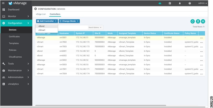
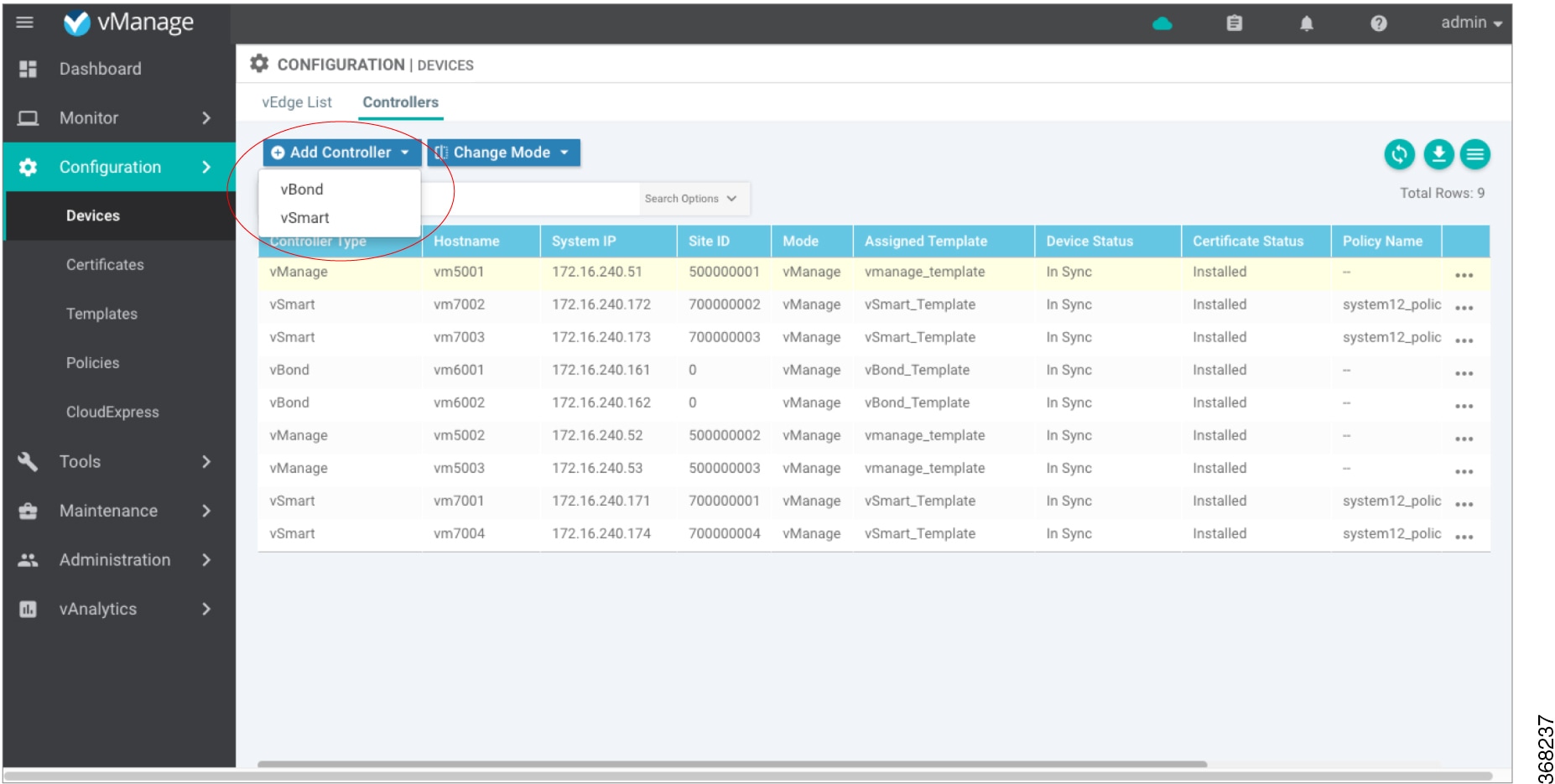
In vManage NMS, select the Configuration ► Devices screen.
-
In the Controllers tab, click Add Controller and select vBond.
-
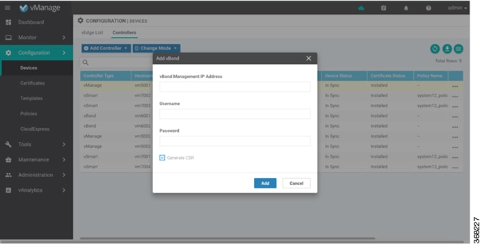
In the Add vBond dialog box:
-
Enter the vBond management IP address.
-
Enter the username and password to access the vBond orchestrator.
-
Select the Generate CSR checkbox to allow the certificate-generation process to occur automatically.
-
Click Add.
-
vManage NMS generates the CSR, retrieves the generated certificate, and automatically installs it on the vBond orchestrator. The new controller device is listed in the Controller table with the controller type, hostname of the controller, IP address, site ID, and other details.
Verify Certificate Installation
To verify that the certificate is installed on a vBond orchestrator:
-
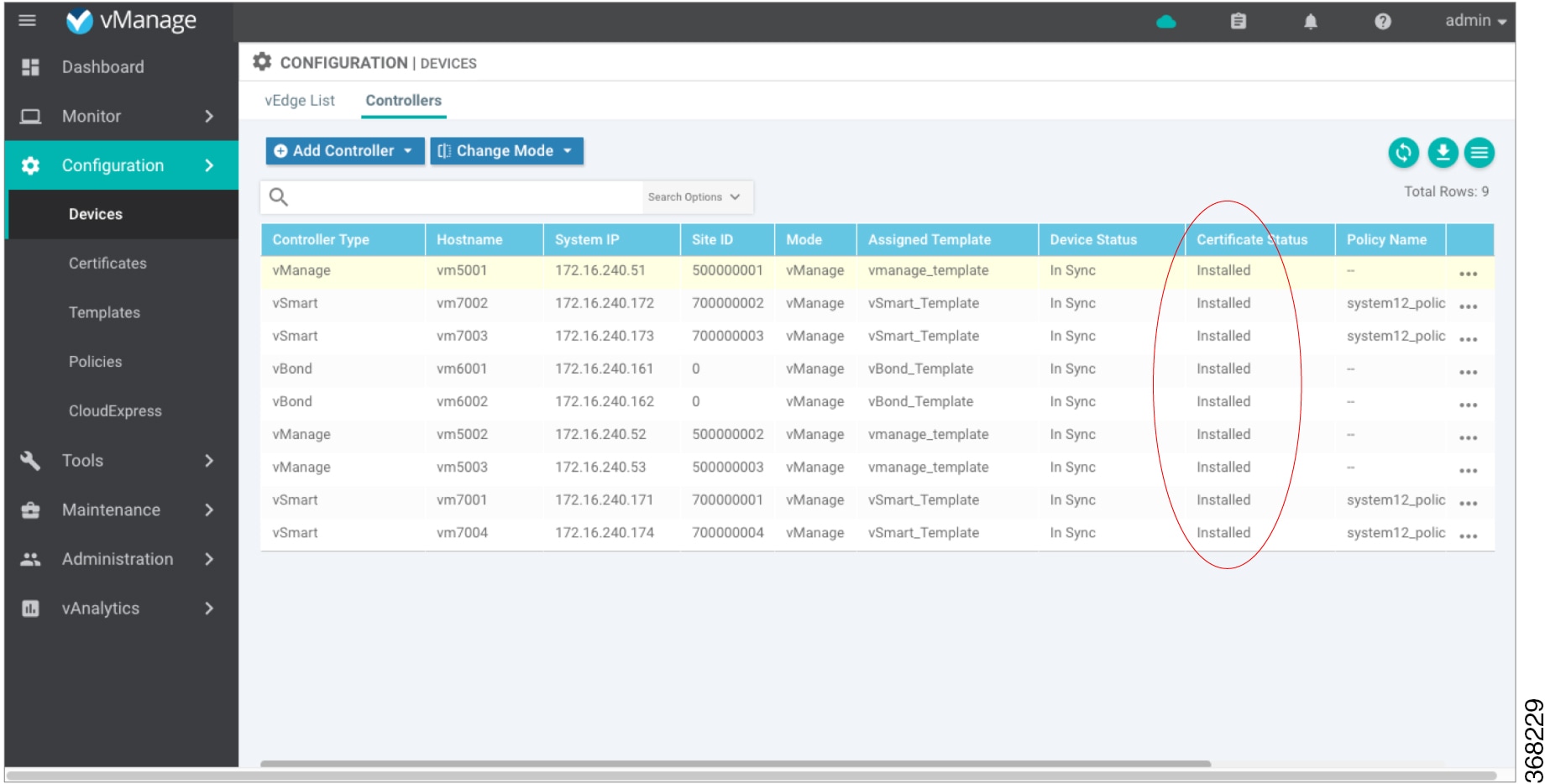
In vManage NMS, select the Configuration ► Devices screen.
-
In the Controller table, select the row listing the new device, and check the Certificate Status column to ensure that the certificate has been installed.
What's Next
See Start the Enterprise ZTP Server.
Add Cisco vManage to a Cluster
To add a new Cisco vManage to the cluster:
-
In the tab, click Add vManage. The Add vManage screen opens.
-
From the Cisco vManage IP Address drop-down list, select an IP address to assign to the Cisco vManage server.
-
Specify a username and password for the Cisco vManage server.
-
Enter the IP address of the Cisco vManage you are adding to the cluster.
-
Specify the username and password for the new Cisco vManage server.
-
Select the services to run on the Cisco vManage server. You can select from the services listed below. Note that the Application Server field is not editable. The Cisco vManage Application Server is the local Cisco vManage HTTP web server.
-
Statistics Database—Stores all real-time statistics from all Cisco SD-WAN devices in the network.
-
Configuration Database—Stores all the device and feature templates and configurations for all Cisco SD-WAN devices in the network.
-
Messaging Server—Distributes messages and shares state among all Cisco vManage cluster members.
-
-
Click Add. The Cisco vManage that you just added then reboots before joining the cluster.
In a cluster, we recommend that you run at least three instances of each service.
Add the vSmart Controller to the Overlay Network
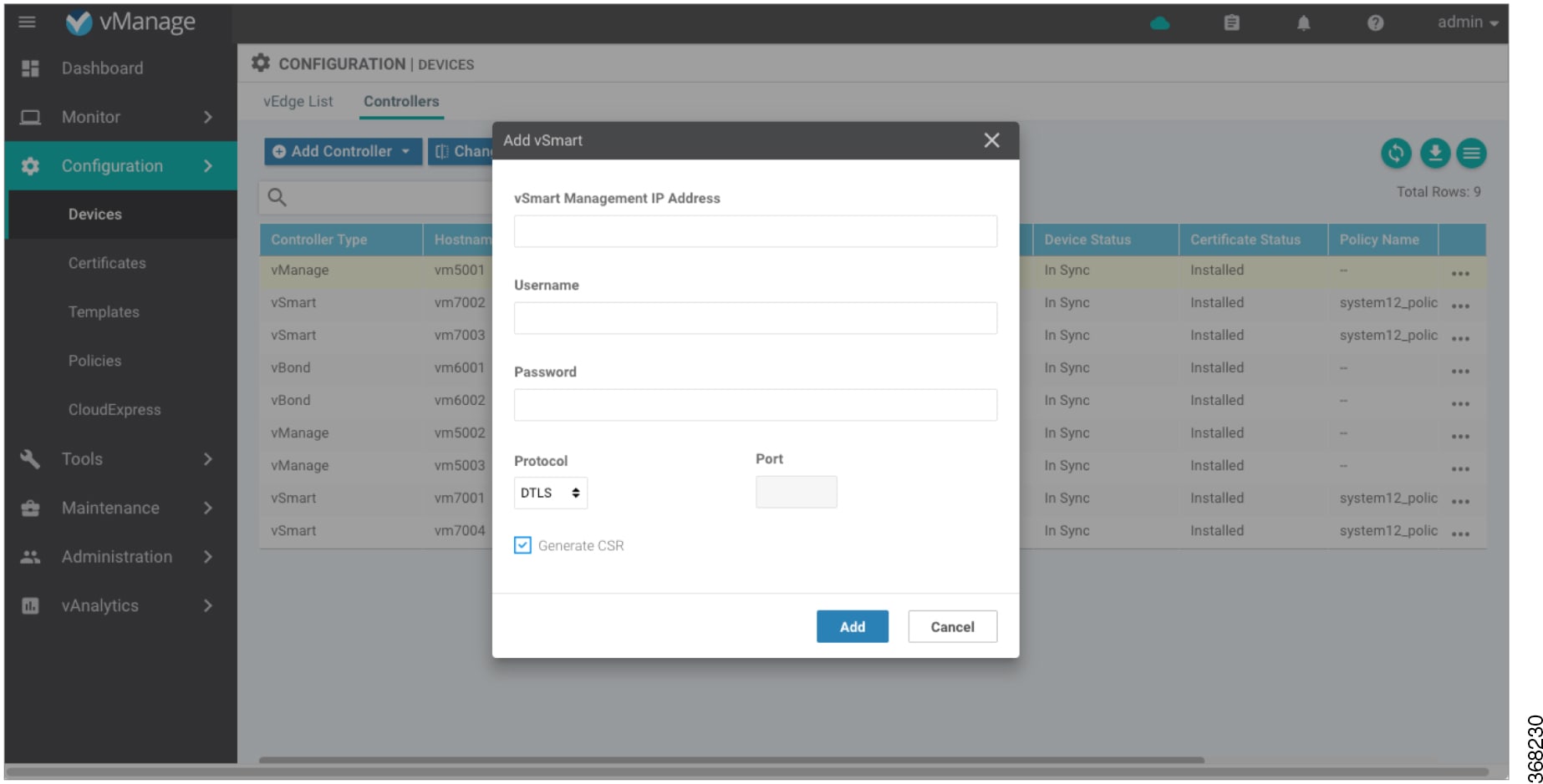
After you create a minimal configuration for the vSmart controller, you must add it to overlay network by making the vManage NMS aware of the controller. When you add a vSmart controller, a signed certificate is generated and is used to validate and authenticate the controller.
The vManage NMS can support up to 20 vSmart controllers in the network.
Add a vSmart Controller and Generate Certificate
To add a vSmart controller to the network, automatically generate the CSR, and install the signed certificate:
-
In vManage NMS, select the Configuration ► Devices screen.
-
In the Controllers tab, click Add Controller and select vSmart.
-
In the Add vSmart dialog box:
-
Enter the system IP address of the vSmart controller.
-
Enter the username and password to access the vSmart controller.
-
Select the protocol to use for control-plane connections. The default is DTLS.
-
If you select TLS, enter the port number to use for TLS connections. The default is 23456.
-
Select the Generate CSR checkbox to allow the certificate-generation process to occur automatically.
-
Click Add.
-
vManage NMS automatically generates the CSR, retrieves the generated certificate, and installs it on the vSmart controller. The new controller is listed in the Controller table with the controller type, hostname of the controller, IP address, site ID, and other details.
Verify Certificate Installation
To verify that the certificate is installed on a vSmart controller:
-
In vManage NMS, select the Configuration ► Devices screen.
-
In the Controllers table, select the row listing the new controller, and check the Certificate Status column to ensure that the certificate has been installed.
What's Next
See Deploy the vEdge Routers.
Apply Policy to a Zone Pair
|
Feature Name |
Release Information |
Description |
|---|---|---|
|
Self Zone Policy for Zone-Based Firewalls |
Cisco IOS XE SD-WAN Release 16.12.1b |
This feature allows you to define firewall policies for incoming and outgoing traffic between a self zone of an edge router and another zone. When a self zone is configured with another zone, the traffic in this zone pair is filtered as per the applied firewall policy. |
 Note |
For IPSEC overlay tunnels in Cisco SD-WAN, if a self zone is selected as a zone pair, firewall sessions are created for SD-WAN overlay BFD packets if inspect action is configured for UDP. |
 Warning |
Control connections may be impacted when you configure drop action from self-zone to VPN0 and vice versa. This applies for DTLS/TLS, BFD packets, and IPsec overlay tunnel. |
Note |
However, for GRE overlay tunnels, if you chose a self zone as a zone pair with the inspect action of protocol 47, firewall sessions are created only for TCP, UDP, ICMP packets; but not BFD packets. |
To apply policy to a zone pair:
- Create security policy using Cisco vManage. See
-
At the top of the page, click Apply Zone-Pairs.
-
In the Source Zone field, choose the zone that is the source of the data packets.
-
In the Destination Zone field, choose the zone that is the destination of the data packets.
Note
You can choose self zone for either a source zone or a destination zone, not both.
-
Click the plus (+) icon to create a zone pair.
-
Click Save.
-
At the bottom of the page, click Save Firewall Policy to save the policy.
-
To edit or delete a firewall policy, click the More Actions icon in the right pane to the far right of the policy, and select the desired option.
-
Click Next to configure the next security block in the wizard.
-
Intrusion Prevention
-
URL Filtering
-
DNS Security
-
Attach and Detach a Device Template
To configure a device on the network, you attach a device template to the device. You can attach only one device template to a device, so the template—whether you created it by consolidating individual feature templates or by entering a CLI text-style configuration—must contain the complete configuration for the device. You cannot mix and match feature templates and CLI-style configurations.
On Cisco Cisco IOS XE SD-WAN devices in the overlay network, you can perform the same operations, in parallel, from one or more vManage servers. You can perform the following template operations in parallel:
-
Attach a device template to devices
-
Detach a device template from a device
-
Change the variable values for a device template that has devices attached to it
For template operations, the following rules apply:
-
When a device template is already attached to a device, you can modify one of its feature templates. Then when you click Update ► Configure Devices, all other template operations—including attach devices, detach devices, and edit device values—are locked on all vManage servers until the update operation completes. This means that a user on another vManage server cannot perform any template operations until the update completes.
-
You can perform the attach and detach device template operations on different devices, from one or more vManage servers, at the same time. However, if any one of these operations is in progress on one vManage server, you cannot edit any feature templates on any of the servers until the attach or detach operation completes.
If the device being configured is present and operational on the network, the configuration is sent to the device immediately and takes effect immediately. If the device has not yet joined the network, the pushing of the configuration to the device is scheduled. When the device joins the network, Cisco vManage pushes the configuration immediately after it learns that the device is present in the network.
Attach a Device Template to Devices
You can attach the same templates to multiple devices, and you can do so simultaneously, in a single operation.
To attach a device template to one or more devices:
-
In the Device tab, select a template.
-
Click the More Actions icon to the right of the row and click Attach Devices. The Attach Devices dialog box opens with the Select Devices tab selected
-
In the Available Devices column on the left, select a group and search for one or more devices, select a device from the list, or click Select All.
-
Click the arrow pointing right to move the device to the Selected Devices column on the right.
-
Click Attach.
-
If the template contains variables, enter the missing variable values for each device you selected in one of the following ways:
-
Enter the values manually for each device either in the table column or by clicking the More Actions icon to the right of the row and clicking Edit Device Template. When you are using optional rows, if you do not want to include the parameter for the specific device, do not specify a value.
-
Click Import File in the upper right corner of the screen to upload a CSV file that lists all the variables and defines each variable's value for each device.
-
Click Update
-
Click Next. If any devices have the same system IP address, a pop-up or an error message is displayed when you click Next. Modify the system IP addresses so that there are no duplicates, and click Save. Then click Next again.
-
In the left pane, select the device, to preview the configuration that is ready to be pushed to the device. The right pane displays the device's configuration and the Config Preview tab in the upper right corner is selected. Click the Config Diff tab to view the differences between this configuration and the configuration currently running on the device, if applicable. Click the Back button to edit the variable values entered in the previous screen.
- If you are attaching a Cisco IOS XE SD-WAN device, click Configure Device Rollback Timer located at
the bottom of the left pane, to configure the time interval at which the device
rolls back to its previous configuration if the router loses its control
connection to the overlay network. The Configure Device Rollback Time dialog box
is displayed.
-
From the Devices drop-down, select a device.
-
To enable the rollback timer, in the Set Rollback slider beneath the Devices drop-down, drag the slider to the left to enable the rollback timer. When you do this, the slider changes in color from gray to green.
-
To disable the rollback timer, click the Enable Rollback slider. When you disable the timer, the Password field pops up. Enter the password that you used to log in to the vManage NMS.
-
In the Device Rollback Time slider, drag the slider to the desired value. The default time is 5 minutes. You can configure a time from 6 to 15 minutes.
-
To exclude a device from the rollback timer setting, click Add Exception and select the devices to exclude.
-
The table at the bottom of the Configure Device Rollback Time dialog box lists all the devices to which you are attaching the template and their rollback time. To delete a configured rollback time, click the Trash icon to the right of the device name.
-
Click Save.
-
-
Click Configure Devices to push the configuration to the devices. The Status column displays whether the configuration was successfully pushed. Click the right angle bracket to the left of the row to display details of the push operation.
Export a Variables Spreadsheet in CSV Format for a Template
-
In the Device tab, select a device template.
-
Click the More Actions icon to the right of the row and click Export CSV.
Change the IP Address of the Current Cisco vManage
We recommend that you configure the IP address of the Cisco vManage server statically, in its configuration file. Configure this IP address on a non-tunnel interface in VPN 0. We recommend that you do not configure DHCP in VPN 512.
When you start Cisco vManage for the first time, the default IP address of the Cisco vManage server is shown as "localhost". Before you can add a new Cisco vManage server to a cluster, you must change localhost to an IP address:
-
In the tab, click Add vManage. The Edit vManage screen opens.
-
From the vManage IP Address drop-down list, select an IP address to assign to the Cisco vManage server.
-
Specify a username and password for the Cisco vManage server.
-
Click Update.
The Cisco vManage server automatically reboots and displays the Cluster Management screen.
Change Configuration Modes
A device can be in either of these configuration modes:
-
vManage mode–A template is attached to the device and you cannot change the configuration on the device by using the CLI.
-
CLI mode – No template is attached to the device and the device can be configured locally by using the CLI.
When you attach a template to a device from vManage, it puts the device in vManage mode. You can change the device back to CLI mode if needed to make local changes to its configuration.
To toggle a router from vManage mode to CLI mode:-
In WAN Edge List tab, select a device.
-
Click the Change Mode drop-down and select CLI mode.
An SSH window opens. To log in to the device, enter a username and password. You can then issue CLI commands to configure or monitor the device.
To toggle a controller device from vManage mode to CLI mode:
-
In the Controllers tab, select a device.
-
Click the Change Mode drop-down.
-
Select CLI mode and then select the device type. The Change Mode CLI window opens.
-
From the vManage mode pane, select the device and click the right arrow to move the device to the CLI mode pane.
-
Click Update to CLI Mode.
An SSH window opens. To log in to the device, enter a username and password. You can then issue CLI commands to configure or monitor the device.
Configure Adaptive QoS
|
Feature Name |
Release Information |
Description |
|---|---|---|
|
Adaptive QoS |
Cisco IOS XE Release 17.3.1a Cisco vManage Release 20.3.1 |
You can now configure adaptive QoS from the Adaptive QoS tab using the Cisco VPN template for one of the supported interfaces. |
To configure adaptive QoS use the Cisco VPN template for one of the following interfaces: Ethernet, Cellular, or DSL.
-
In Cisco vManage, navigate to .
-
Click the Feature tab and then click Add Template.
-
Choose a device from the list on the left. Feature templates that are applicable to the device are shown in the right pane.
-
Choose one of the available Cisco VPN Interface templates. In this example, we've chosen the Cisco VPN Interface Ethernet template.
-
Enter a name and description for the feature template.
-
Click the ACL/QoS tab.
-
Notice that Adaptive QoS is disabled by default. To enable it, from the Adaptive QoS drop-down list, choose Global, and click the On radio button.
-
(Optional) Enter adaptive QoS parameters. You can leave the additional details at as default or specify your values.
-
Adapt Period: Choose Global from the drop-down list, click the On radio button, and enter the period in minutes.
-
Shaping Rate Upstream: Choose Global from the drop-down list, click the On radio button and enter the minimum, maximum, and default upstream bandwidth in Kbps.
-
Shaping Rate Downstream: Choose Global from the drop-down list, click the On radio button, and enter the minimum, maximum, downstream, and upstream bandwidth in Kbps.
-
-
Click Save.
Configure BFD for Routing Protocols
|
Feature Name |
Release Information |
Description |
|---|---|---|
|
BFD for Routing Protocols in Cisco SD-WAN |
Cisco IOS XE Release 17.3.1a Cisco vManage Release 20.3.1 |
You can now use the CLI Add-on feature templates in Cisco vManage to configure BFD for supported routing protocols. |
Cisco vManage does not provide an independent template to configure BFD for routing protocols. However, supported protocols can be registered or deregistered to received BFD packets by adding configurations using the CLI add-on template in Cisco vManage. Use the CLI add-on template to configure the following:
-
Add a single-hop BFD template with parameters such as timer, multiplier, session mode, and so on.
-
Enable the BFD template under interfaces. Only one BFD template can be added per interface.
-
Enable or disable BFD for the supported routing protocols. The configuration to enable or disable BFD is different for each of the supported routing protocols: BGP, EIGRP, OSPF, and OSPFv3.
Configure BFD for Service-Side BGP
-
In Cisco vManage, select
-
Click the Feature tab.
-
Click Add Template.
-
Choose a device from the device list in the left pane.
-
Choose the CLI Add-on Template under Other Templates.
-
Enter the CLI configuration to add a single-hop BFD template and to enable BFD for service-BGP as shown in the following example.
bfd-template single-hop t1
 interval min-tx 500 min-rx 500 multiplier 3
 !
interface GigabitEthernet1
   bfd template t1

router bgp 10005
address-family ipv4 vrf 1
    neighbor 10.20.24.17 fall-over bfd
    !
  address-family ipv6 vrf 1
    neighbor 2001::7 fall-over bfd
Understanding the CLI Configuration
In this example, a single hop BFD template is created specifying the minimum and maximum interval and the multiplier. Specifying these parameters is mandatory. In addition, you have the option to also specify other BFD parameters such as echo mode (enabled by default), and BFD dampening (off by default). Once created, the BFD template is enabled under an interface (GigabitEthernet1, in this example).
Note
To modify a BFD template enabled on an interface, you need to remove the existing template first, modify it, and then enable it on the interface again.
-
Click Save.
-
Attach the CLI Add-on Template with this configuration to the device template.
Note
For the configuration to take effect, the device template must have a BGP feature template attached to it.
Configure BFD for Transport-Side BGP
-
In Cisco vManage, select
-
Click the Feature tab.
-
Click Add Template.
-
Choose a device from the device list in the left pane.
-
Choose the CLI Add-on Template under Other Templates.
-
Enter the CLI configuration to add a single-hop BFD template and to enable BFD for transport-BGP as shown in the following example.
bfd-template single-hop t1
interval min-tx 500 min-rx 500 multiplier 3
!
interface GigabitEthernet1
bfd template t1
!
router bgp 10005
neighbor 10.1.15.13 fall-over bfd
!
sdwan
interface GigabitEthernet1
tunnel-interface
allow-service bfd
allow-service bgp
Understanding the CLI Configuration
In this example, a single hop BFD template is created specifying the minimum and maximum interval and the multiplier. Specifying these parameters is mandatory. In addition, you have the option to also specify other BFD parameters such as echo mode (enabled by default), and BFD dampening (off by default). Once created, the BFD template is enabled under an interface (GigabitEthernet1, in this example). In this example, GigabitEthernet1 is also the source of the SD-WAN tunnel. Allowing service under the tunnel interface of GigabitEthernet1 ensures that BGP and BFD packets pass over the tunnel.
Note
To modify a BFD template enabled on an interface, you need to remove the existing template first, modify it, and then enable it on the interface again.
-
Click Save.
-
Attach the CLI Add-on Template with this configuration to the device template.
Note
For the configuration to take effect, the device template must have a BGP feature template attached to it.
Configure BFD for Service-Side EIGRP
-
In Cisco vManage, select
-
Click the Feature tab.
-
Click Add Template.
-
Choose a device from the device list in the left pane.
-
Choose the CLI Add-on Template under Other Templates.
-
Enter the CLI configuration to add a single-hop BFD template enable BFD for EIGRP as shown in the example below.
bfd-template single-hop t1
 interval min-tx 500 min-rx 500 multiplier 3
 !
interface GigabitEthernet5
   bfd template t1

router eigrp myeigrp
address-family ipv4 vrf 1 autonomous-system 1
    af-interface GigabitEthernet5
     bfd
Understanding the CLI Configuration
In this example, a single hop BFD template is created specifying the minimum and maximum interval and the multiplier. Specifying these is mandatory. In addition, you have the option to also specify other BFD parameters such as echo mode (enabled by default), and BFD dampening (off by default).
Once created, the BFD template is enabled under an interface (GigabitEthernet5, in this example).
Note
To modify a BFD template enabled on an interface, you first need to remove the existing template, modify it, and enable it on the interface again.
-
Click Save.
-
Attach the CLI Add-on Template with this configuration to the device template.
Note
For the configuration to take effect, the device template must have an EIGRP feature template attached to it.
Configure BFD for Service-Side OSPF and OSPFv3
-
In Cisco vManage, select
-
Click the Feature tab.
-
Click Add Template.
-
Choose a device from the device list in the left pane.
-
Choose the CLI Add-on Template under Other Templates.
-
Enter the CLI configuration to add a single-hop BFD template enable BFD for OSPF and OSPFv3 as shown in the examples below.
OSPF
bfd-template single-hop t1
interval min-tx 500 min-rx 500 multiplier 3
!
interface GigabitEthernet5
bfd template t1
!
interface GigabitEthernet1
bfd template t1
!
router ospf 1 vrf 1
 bfd all-interfaces
!
OSPFv3
bfd-template single-hop t1
 interval min-tx 500 min-rx 500 multiplier 3

interface GigabitEthernet5
   bfd template t1
router ospfv3 1
 address-family ipv4 vrf 1
  bfd all-interfaces
Understanding the CLI Configuration
In these examples, a single hop BFD template is created specifying the minimum and maximum interval and the multiplier. Specifying these is mandatory. In addition, you have the option to also specify other BFD parameters such as echo mode (enabled by default), and BFD dampening (off by default).
Once created, the BFD template is enabled under an interface (GigabitEthernet5, in this example).
Note
To modify a BFD template enabled on an interface, you first need to remove the existing template, modify it, and enable it on the interface again.
-
Click Save.
-
Attach the CLI Add-on Template with this configuration to the device template.
Note
For the configuration to take effect, the device template must have an OSPF feature template attached to it.
Configure or Cancel vManage Server Maintenance Window
You can set or cancel the start and end times and the duration of the maintenance window for the vManage server.
-
In vManage NMS, select the screen.
-
Click the Edit button to the right of the Maintenance Window bar.
To cancel the maintenance window, click Cancel.
-
Click the Start date and time drop-down, and select the date and time when the maintenance window will start.
-
Click the End date and time drop-down, and select the date and time when the maintenance window will end.
-
Click Save. The start and end times and the duration of the maintenance window are displayed in the Maintenance Window bar.
Two days before the start of the window, the vManage Dashboard displays a maintenance window alert notification.
Configure Certificate Authorization Settings for WAN Edge Routers
Certificates are used to authenticate routers in the overlay network. Once authentication is complete, the routers can establish secure sessions with other devices in the overlay network.
By default, the WAN Edge Cloud Certificate Authorization is automated. This is the recommended setting.
If you use third-party certificate authorization, configure certificate authorization to be manual:
-
In Cisco vManage, navigate to .
-
Click Edit to the right of the Hardware WAN Edge Certificate Authorization bar.
-
In the Security field, select Enterprise Certificate (signed by Enterprise CA).
-
Click Save.
Configure Certificate Settings
New controller devices in the overlay network—Cisco vManage instances, vBond orchestrators, and vSmart controllers—are authenticated using signed certificates. From the Cisco vManage, you can automatically generate the certificate signing requests (CSRs), retrieve the generated certificates, and install them on all controller devices when they are added to the network.
Note |
All controller devices must have a certificate installed on them to be able to join the overlay network. |
To automate the certification generation and installation process, configure the name of your organization and certificate authorization settings before adding the controller devices to the network.
For more information, see Certificates.
Configure Cloud onRamp for IaaS for Amazon Web Services
Before you begin
A series of considerations are essential to configure Cloud onRamp for IaaS for AWS.
-
Transit VPCs provide the connection between the Cisco overlay network and the cloud-based applications running on host VPCs. Each transit VPC consists of up to four pairs of cloud routers that reside in their own VPC. Multiple routers are used to provide redundancy for the connection between the overlay network and cloud-based applications. On each of these two cloud routers, the transport VPN (VPN 0) connects to a branch router, and the service-side VPNs (any VPN except for VPN 0 and VPN 512) connect to applications and application providers in the public cloud.
-
Cloud onRamp supports auto-scale for AWS. To use auto-scale, ensure that you associate two to four pairs of cloud routers to a transit VPC. Each of the devices that are associated with the transit VPC for auto-scale should have a device template attached to it.
-
Host VPCs are virtual private clouds in which your cloud-based applications reside. When a transit VPC connects to an application or application provider, it is simply connecting to a host VPC.
-
All host VPCs can belong to the same account, or each host VPC can belong to a different account. A host that belongs one account can be mapped to a transit VPC that belongs to a completely different account. You configure cloud instances by using a configuration wizard.
Procedure
| Step 1 |
In Cisco vManage, select . 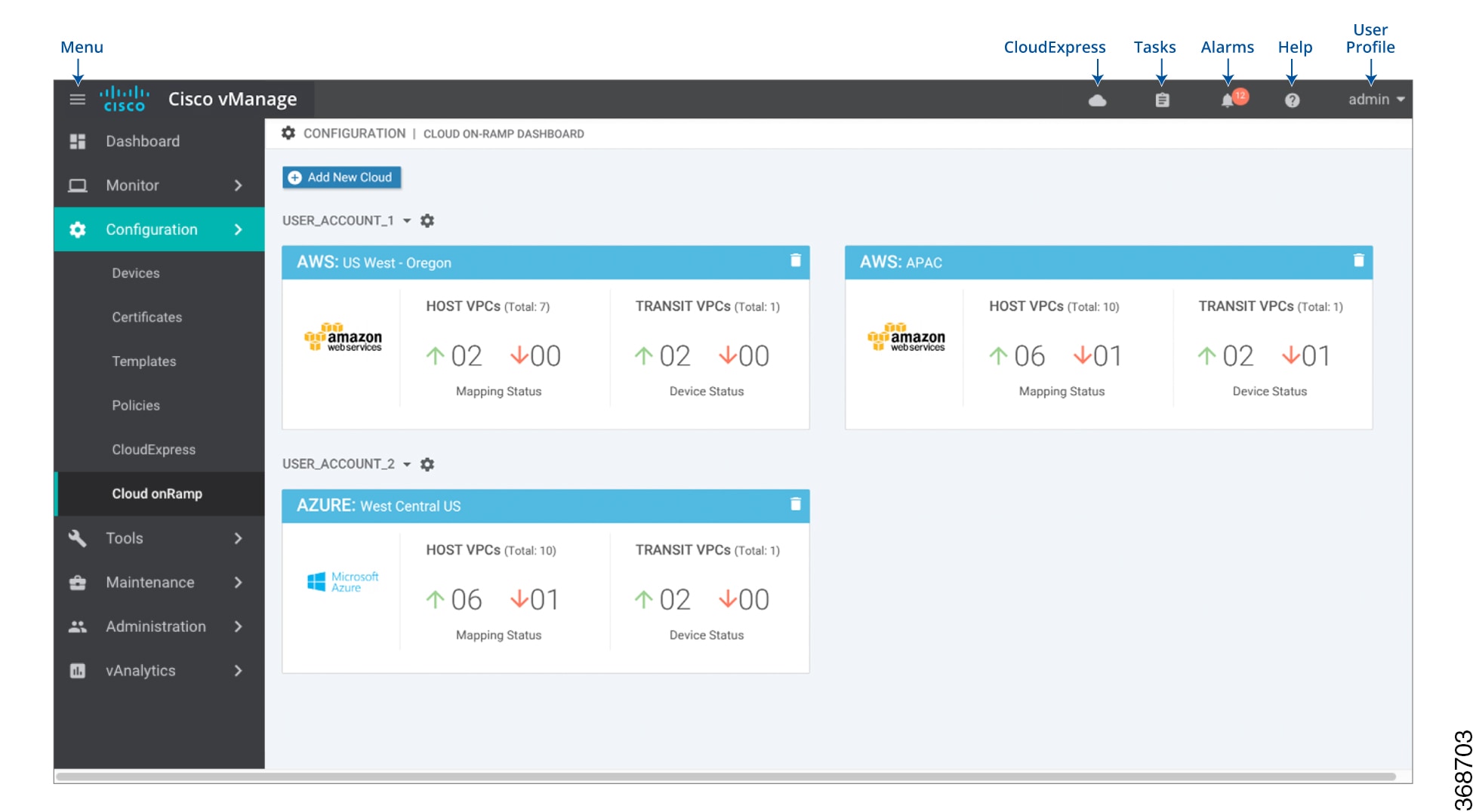
|
| Step 2 |
Click Add New Cloud Instance. |
| Step 3 |
In the Add Cloud Instance – log in to a Cloud Server popup: |
| Step 4 |
Click Login to log in to the cloud server. The cloud instance configuration wizard opens. This wizard consists of three screens that you use to select a region and discover host VPCs, add transit VPC, and map host VPCs to transit VPCs. A graphic on the right side of each wizard screen illustrates the steps in the cloud instance configuration process. The steps that are not yet completed are shown in light gray. The current step is highlighted within a blue box. Completed steps are indicated with a green checkmark and are shown in light orange. |
| Step 5 |
Select a region:
|
| Step 6 |
Add a transit VPC:
|
| Step 7 |
Map the host VPCs to transit VPCs:
In the VPN feature configuration template for VPN 0, when configuring the two cloud routers that form the transit VPC, ensure that the color you assign to the tunnel interface is a public color, not a private color. Public colors are 3g, biz-internet, blue, bronze, custom1, custom2, custom3, default, gold, green, lte, metro-ethernet, mpls, public-internet, red, and silver. |
 .
.
 .
.
Display Host VPCs
Procedure
| Step 1 |
In the Cloud OnRamp Dashboard, click the pane for the desired VPC. The Host VPCs/Transit VPCs screen opens, and Host VPCs is selected by default. In the bar below this, Mapped Host VPCs is selected by default, and the table on the screen lists the mapping between host and transit VPCs, the state of the transit VPC, and the VPN ID. |
| Step 2 |
To list unmapped host VPCs, click Unmapped Host VPCs. Then click Discover Host VPCs. |
| Step 3 |
To display the transit VPCs, click Transit VPCs. |
Map Host VPCs to a Transit VPC
Procedure
| Step 1 |
In the Cloud OnRamp Dashboard, click the pane for the desired VPC. The Host VPCs/Transit VPCs screen opens. |
| Step 2 |
Click Un-Mapped Host VPCs. |
| Step 3 |
Click Discover Host VPCs. |
| Step 4 |
From the list of discovered host VPCs, select the desired host VPCs. |
| Step 5 |
Click Map VPCs. The Map Host VPCs popup opens. |
| Step 6 |
In the \ drop-down, choose the desired transit VPC. |
| Step 7 |
In the VPN drop-down, choose the VPN in the overlay network in which to place the mapping. |
| Step 8 |
Click Map VPCs. |
Unmap Host VPCs
Procedure
| Step 1 |
In the Cloud OnRamp Dashboard, click the pane for the desired VPC. The Host VPCs/Transit VPCs screen opens. |
| Step 2 |
Click Mapped Host VPCs. |
| Step 3 |
From the list of VPCs, select the desired host VPCs. |
| Step 4 |
Click Unmap VPCs. |
| Step 5 |
Click OK to confirm the unmapping. |
Unmapping host VPCs deletes all VPN connections to the VPN gateway in the host VPC, and then deletes the VPN gateway. When you make additional VPN connections to a mapped host VPC, they will be terminated as part of the unmapping process.
Display Transit VPCs
Procedure
| Step 1 |
In the Cloud OnRamp Dashboard, click the pane for the desired VPC. The Host VPCs/Transit VPCs screen opens, and Host VPCs is selected by default. |
| Step 2 |
Click Transit VPCs. |
Add Transit VPC
Procedure
| Step 1 |
In the Cloud onRamp Dashboard, click the pane for the desired VPC. The Host VPCs/Transit VPCs screen opens, and Host VPCs is selected by default. |
| Step 2 |
Click Transit VPCs. |
| Step 3 |
Click Add Transit VPC. To add a transit VPC, perform operations from step 6 of Configure Cloud onRamp for IaaS for Amazon Web Services. |
Delete Device Pair
Before you begin
Procedure
| Step 1 |
Go to the Cloud onRamp Dashboard. |
| Step 2 |
Click a device pair ID. |
| Step 3 |
Verify that the status of the device pair is offline. |
| Step 4 |
To descale the device pairs, click the trash can icon in the Action column or click the Trigger Autoscale option. |
Delete Transit VPC
Note |
To delete the last pair of online device pairs, you must delete a transit VPC. |
Before you begin
Procedure
| Step 1 |
In the Cloud onRamp Dashboard, click the pane for the desired VPC. The Host VPCs/Transit VPCs screen opens, and Host VPCs is selected by default. |
||
| Step 2 |
Click Host VPCs. |
||
| Step 3 |
Select all host VPCs, and click Unmap VPCs. Ensure that all host mappings with transit VPCs are unmapped. |
||
| Step 4 |
Click OK to confirm the unmapping. |
||
| Step 5 |
Click Transit VPCs. |
||
| Step 6 |
Click the trash icon to the left of the row for the transit VPC.
|
||
| Step 7 |
Click OK to confirm. |
Add Device Pairs
Procedure
| Step 1 |
Click Add Device Pair.
|
||
| Step 2 |
In the box, select a device pair. |
||
| Step 3 |
Click the Add icon to add more device pairs. You can add up to a total of four device pairs to the transit VPC. |
||
| Step 4 |
Click Save. |
History of Device Pairs for Transit VPCs
Procedure
| Step 1 |
To display the Transit VPC Connection History page with all the corresponding events, click History for a device pair. |
| Step 2 |
View a histogram of events that have occurred in the previous one hour is displayed and a table of all events for the selected transit VPC. The table lists all the events generated in the transit VPC. The events can be one of the following:
|
Edit Transit VPC
Procedure
| Step 1 |
Click Edit Transit Details. Provide a value for the maximum number of host VPCs per device pair to which the transit VPC can be mapped. |
| Step 2 |
Click OK. This operation can trigger auto-scale. |
Configure Cloud onRamp for Multi-Cloud through vManage
|
Feature Name |
Release Information |
Description |
|---|---|---|
|
Integration of AWS Branch with Cisco IOS XE SD-WAN Devices |
Cisco IOS XE Release 17.3.1a Cisco vManage Release 20.3.1 |
You can configure Cloud onRamp on Multi-Cloud environment using the Cloud OnRamp for Multi-Cloud option under the Configuration tab. |
To create a new account for cloud onRamp for multi-cloud:
-
In Cisco vManage, navigate to . The Cloud onRamp for Multi-Cloud dashboard displays.
-
Click Account Creation in the Setup pane. The Associate Cloud Account page appears.
-
Enter the account name in the Account Name field.
-
(Optional) Enter the description in the Description field.
-
In the Use for Cloud Gateway, choose Yes if you want to create cloud gateway in your account, else select No.
-
Choose the authentication model you want to use in the field Login in to AWS With.
-
Key
-
IAM Role
If you choose Key model, then provide API Key and Secret Key in the respective fileds.
OrIf you choose IAM Role model, then provide Role ARN and External Id details.
-
-
Click Add.
| Parameter |
Description |
|---|---|
| Account Name |
Specifies the cloud account name. |
| Description |
(Optional) Specifies the cloud account desciption. |
| Use for Cloud Gateway |
Specifies if the account is created to launch Cloud Gateway. The options are: Yes or No |
| Login in to AWS With |
Specifies the authentication model you want to use. The model options are:
|
| Key | API Key - Specifies the Amazon API key. |
| Secret Key - Specifies the password associated with the API key. | |
| IAM Role | Role ARN - Specifies the role ARN of the IAM role. |
| External Id - Specifies the external ID that is created for the role ARN. |
To view or update cloud account details, click ... button on the Cloud Account Management page.
You can also remove the cloud account if there are no associated host VPC tags or cloud gateways.
Configure Cisco TGW Global Settings
To add Cisco TGW global settings, perform the following steps:
-
On the Cloud onRamp for Multi-Cloud dashboard, click Global Settings in the Setup pane. The Global Settings page appears.
-
Click the Software Image drop-down list to select the pre-installed or the subscibed CSR image.
-
Click the Instance Size drop-down list to choose the required size.
-
Click Cloud Gateway Solution drop-down list to choose the AWS Transit Gateway and CSR in Transit VPC.
-
Enter the IP Subnet Pool.
-
Enter the Cloud Gateway BGP ASN Offset.
-
Choose the Intra Tag Communication. The options are Enabled or Disabled.
-
Choose the Default Route. The options are Enabled or Disabled.
-
Click Update.
| Parameter |
Description |
|---|---|
| Software Image |
Specifies the preinstalled or the subscibed software images for your account. |
| Instance Size |
Specifies the instance size. The options are:
|
| Cloud Gateway Solution |
Specifies the combination of the Cloud Gateway Solution. For example, AWS Transit Gateway and CSR in Transit VPC. |
| IP Subnet Pool |
Specifies the list of IP subnets separated by comma in CIDR format. More than one subnets can be specified. A single /24 subnet pool is able to support one cloud gateway only. You cannot modify the pool when a few cloud gateways are already making use of pool. Overlapping of subnets is not allowed. |
| Cloud Gateway BGP ASN Offset |
Specifies the offset for allocation of TGW BGP ASNs. It is used to block routes learnt from one TGW (eBGP) to another TGW. A band of 30 ASNs are reserved for TGW ASNs. Starting offset plus 30 will be the organization side BGP ASN. For example, if the offset is 64830, Org BGP ASN will be 64860. Acceptable start offset range is 64520 to 65500. It must be a multiple of 10. |
| Intra Tag Communication |
Specifies if the communication between host VPCs under the same tag is enabled or disabled. If any tagged VPCs are already present and cloud gateways exist in those regions, then this flag cannot be changed. |
| Program Default Route in VPCs towards TGW |
Specifies if the main route table of the host VPCs is programmed with default route is enabled or disabled. |
|
Item |
Changeable after cloud gateway is created (Yes/No) |
Default (Enabled/Disabled) |
|---|---|---|
| Software Image |
Yes |
NA |
| Instance Size |
Yes |
NA |
| IP Subnet Pool |
See the description below |
NA |
| Cloud Gateway BGP ASN Offset |
No |
NA |
| Intra Tag Communication |
Cannot be changed if both cloud gateways and tagged host VPCs exist in any region |
Enabled at the API level |
| Program Default Route in VPCs towards TGW |
No |
Enabled at the API level |
Global IP Subnet Pool – can only be updated if there is no cloud gateway using global subnet pool. A cloud gateway uses global subnet pool whether it has custom setting or not. The subnet pool value is similar to the one in global setting (you can compare after splitting the list of CIDRs by comma; for example, 10.0.0.0/8, 10.255.255.254/8 and 10.255.255.254/8, 10.0.0.0/8 are similar).
If there is no cloud gateway using global subnet pool, the updated subnet pool in the global setting should not overlap with any of the existing custom subnet pools.
Custom IP Subnet Pool – when a custom setting is created, its subnet pool should not overlap with any of the existing custom subnet pools. It cannot partially overlap with the configured global subnet pool.
Discover Host VPCs
You can discover host VPCs in all the accounts across all the respective regions of the account that are available. When the Host VPC Discovery is invoked, the discovery of the VPCs is performed without any cache.
-
In the Cloud onRamp for Multi-Cloud dashboard, click on Host VPCs in the Discover pane. The Discover Host VPCs screen appears with the list of available VPCs.
The host VPC table includes the following columns:
-
Cloud Region
-
Account Name
-
Host VPC Name
-
Host VPC Tag
-
Account ID
-
Host VPC ID
You click any column to sort the VPCs as required.
-
-
Click the Region drop-down list to select the VPCs based on particular region.
-
You can click Tag Actions to perform the following actions:
-
Add Tag - group the selected VPCs and tag them together.
-
Edit Tag - migrate the selected VPCs from one tag to another.
-
Delete Tag - remove the tag for the selected VPCs.
A number of host VPCs can be grouped under a tag. VPCs under the same tag are considered as a singular unit.
-
Create Cloud Gateway
Cloud gateway is an instantiation of Transit VPC (TVPC), CSRs within TVPC and TGW in the cloud. To create a cloud gateway, perform the following steps:
-
In the Cloud onRamp for Multi-Cloud dashboard, click Create Cloud Gateway in the Manage pane. The Manage Cloud Gateway - Create screen appears.
-
In the Cloud Gateway field, enter the cloud gateway name.
-
(Optional) In the Description, enter the description.
-
Choose the account name from the Account Name drop-down list.
-
Choose the region from the Region drop-down list.
-
(Optional) Choose the SSH Key from the drop-down list.
-
Choose the UUID details in the UUID (specify 2) drop-down list.
-
In the Settings field, select the required option. The options are:
-
Default
-
Customized - you can override the global settings. The selection is applicable only for the newly created cloud gateway.
-
-
Click Add to create a new cloud gateway.
Configure Cloud onRamp for SaaS
|
Feature Name |
Release Information |
Description |
|---|---|---|
|
Support for Specifying Office 365 Traffic Categories for Cloud onRamp for SaaS on Cisco IOS XE SD-WAN Devices |
Cisco IOS XE Release 17.3.1a Cisco vManage Release 20.3.1 |
Using Cloud onRamp for SaaS, you can select specific SaaS applications and interfaces, and let Cisco SD-WAN determine the best performing path for each SaaS applications. For Cisco IOS XE SD-WAN devices, you can also limit the use of best path selection to some or all Office 365 traffic, according to the Office 365 traffic categories defined by Microsoft. |
Enable Cloud OnRamp for SaaS
-
In Cisco vManage, click Administration > Settings.
-
Click Edit, to the right of the Cloud onRamp for SaaS bar.
-
In the Cloud onRamp for SaaS field, click Enabled.
-
Click Save.
Configure Applications for Cloud onRamp for SaaS Using Cisco vManage
-
Open Cloud onRamp for SaaS.
-
In Cisco vManage, open Configuration > Cloud onRamp for SaaS.
or
-
In Cisco vManage, click the cloud icon near the top right and select Cloud onRamp for SaaS.
-
-
In the dropdown, select Applications and Policy.
The Applications and Policy page shows a table of SaaS applications.
-
Enable applications and configure.
Column
Description
Applications
Applications that can be used with Cloud onRamp for SaaS
Monitoring
Enabled: Enables Cloud OnRamp for SaaS to initiate the Quality of Experience probing to find the best path.
Disabled: Cloud onRamp for SaaS stops the Quality of Experience probing for this application.VPN
(Cisco vEdge devices) Specify one or more VPNs.
Policy/Cloud SLA
(Cisco IOS XE SD-WAN devices) Select Enable to enable Cloud onRamp for SaaS to use the best path for this application.
Note You can select Enable only if there is a centralized policy that includes an application-aware policy has been activated.
(Cisco IOS XE SD-WAN devices) For Office 365, select one of the following to specify which types of Office 365 traffic to include:
-
Optimize: Include only Office 365 traffic categorized as “optimize” – the traffic most sensitive to network performance, latency, and availability.
-
Optimize and Allow: Include only Office 365 traffic categorized as “Optimize” or “Allow”. The “Allow” category of traffic is less sensitive to network performance and latency than the “Optimize” category.
-
All: Include all Office 365 traffic.
-
-
Click Save Applications and Next.
If new applications were enabled, a page appears, displaying all of the application-aware policies in the centralized policy.
-
You can select a policy and view the policy details.
-
You can delete one or more new sequences that have been added for the SaaS applications, or change the order of the sequences.
-
You can create a new policy for sites that are not included in existing centralized policies. If you create a new policy, you must add a VPN list for the policy.
-
For an existing policy, you cannot edit the site list or VPN list.
-
-
Click Save Policy and Next. This pushes the policy to the Cisco vSmart Controller.
Configure Client Sites
To configure Cloud OnRamp for SaaS on client sites that access the internet through gateways, you must configure Cloud OnRamp for SaaS both on the client sites and on the gateway sites.
Note |
You cannot configure Cloud OnRamp for SaaS with Point-to-Point Protocol (PPP) interface on the gateway sites. |
Client sites in Cloud onRamp service choose the best gateway site for each application to use for accessing the internet.
-
In Cisco vManage, select the screen. The Cloud OnRamp for SaaS Dashboard screen opens.
-
From the Manage Cloud OnRamp for SaaS drop-down, located to the right of the title bar, select Client Sites. The screen changes and displays the following elements:
-
Attach Sites—Add client sites to Cloud onRamp for SaaS service.
-
Detach Sites—Remove client sites from Cloud onRamp for SaaS service.
-
Client sites table—Display client sites configured for Cloud onRamp for SaaS service.
-
-
On the Manage Sites screen, click Attach Sites. The Attach Sites screen displays all sites in the overlay network with available sites highlighted. For a site to be available, all devices at that site must be running in vManage mode.
-
In the Available Sites pane, select a client site to attach and click the right arrow. To remove a site, select it in the Selected Sites pane and click the left arrow.
-
Click Attach. The Cisco vManage NMS pushes the feature template configuration to the devices. The Task View window displays a Validation Success message.
-
Select to return to the Cloud OnRamp for SaaS Dashboard screen.
-
From the Manage Cloud OnRamp for SaaS drop-down, located to the right of the title bar, choose Gateways. The screen changes and displays the following elements:
-
Attach Gateways—Attach gateway sites.
-
Detach Gateways—Remove gateway sites from the Cloud onRamp service.
-
Edit Gateways—Edit interfaces on gateway sites.
-
Gateways table—Display gateway sites configured for Cloud onRamp service.
-
-
On the Manage Gateways screen, click Attach Gateways. The Attach Gateways popup window displays all sites in your overlay network with available sites highlighted. For a site to be available, all devices at that site must be running in vManage mode.
-
In the Device Class field, select one of the following:
-
Cisco OS (cEdge): Cisco IOS XE SD-WAN devices
-
Viptela OS (vEdge): Cisco vEdge devices
-
-
In the Available Gateways pane, select a gateway site to attach and click the right arrow. To remove a site, select the site in the Selected Sites pane and click the left arrow.
-
(Cisco vEdge devices) If you do not specify interfaces for Cloud OnRamp for SaaS to use, the system selects a NAT-enabled physical interface from VPN 0. To specify GRE interfaces for Cloud OnRamp for SaaS to use:
-
Click the link Add interfaces to selected sites (optional), located in the bottom right corner of the window.
-
In the Select Interfaces drop-down, select GRE interfaces to add.
-
Click Save Changes.
-
-
(Cisco IOS XE SD-WAN devices) If you do not specify interfaces for Cloud OnRamp for SaaS, an error message indicates that the interfaces are not VPN 0.
-
Click the link Add interfaces to selected sites, located in the bottom right corner of the window.
-
In the Select Interfaces drop-down, select Select Interfaces to Add.
-
Click Save Changes.
-
-
Click Attach. The Cisco vManage NMS pushes the feature template configuration to the devices. The Task View window displays a Validation Success message.
-
To return to the Cloud OnRamp for SaaS Dashboard, select .
To edit Cloud OnRamp for SaaS interfaces on gateway sites:
-
Select the sites you want to edit and click Edit Gateways.
-
In the Edit Interfaces of Selected Sites screen, select a site to edit.
-
To add interfaces, click the Interfaces field to select available interfaces.
-
To remove an interface, click the X beside its name.
-
-
Click Save Changes to push the template to the device(s).
Configure Direct Internet Access (DIA) Sites
-
In Cisco vManage, select the screen. The Cloud OnRamp for SaaS Dashboard screen opens.
-
From the Manage Cloud OnRamp for SaaS drop-down, located to the right of the title bar, choose Direct Internet Access (DIA) Sites.
The page provides options to attach, detach, or edit DIA sites, and shows a table of sites configured for Cloud onRamp service.
-
Click Attach DIA Sites. The Attach DIA Sites popup window displays all sites in your overlay network with available sites highlighted. For a site to be available, all devices at that site must be running in vManage mode.
-
In the Device Class field, select one of the following:
-
Cisco OS (cEdge): Cisco IOS XE SD-WAN devices
-
Viptela OS (vEdge): Cisco vEdge devices
-
-
In the Available Sites pane, select a site to attach and click the right arrow. To remove a site, select it in the Selected Sites pane and click the left arrow.
-
(For Cisco vEdge devices) If you do not specify interfaces for Cloud OnRamp for SaaS to use, the system selects a NAT-enabled physical interface from VPN 0. To specify GRE interfaces for Cloud OnRamp for SaaS to use:
-
Click the link, Add interfaces to selected sites (optional), located in the bottom right corner of the window.
-
In the Select Interfaces drop-down, choose GRE interfaces to add.
-
Click Save Changes.
-
-
(For Cisco IOS XE SD-WAN devices, optional) Specify TLOCs for a site.
Note
If you do not specify TLOCs, the All DIA TLOC option is used by default.
-
Click the Add TLOC to selected sites link at the bottom right corner of the popup window.
-
In the Edit Interfaces of Selected Sites popup window, select All DIA TLOC, or select TLOC List and specify a TLOC list.
-
Click Save Changes.
-
-
Click Attach. The Cisco vManage NMS pushes the feature template configuration to the devices. The Task View window displays a Validation Success message.
-
To return to the Cloud OnRamp for SaaS Dashboard, choose .
To edit Cloud onRamp interfaces on DIA sites:
-
Select the sites to edit and click Edit DIA Sites.
-
(Cisco vEdge devices) On the Edit Interfaces of Selected Sites screen, select a site to edit.
-
To add interfaces, click the Interfaces field to select available interfaces.
-
To remove an interface, click the X beside its name.
-
-
(Cisco IOS XE SD-WAN devices) On the Edit TLOCs of Selected Sites screen, select a site to edit, and edit the TLOC list.
-
Click Save Changes to push the new template to the devices.
To return to the Cloud OnRamp for SaaS Dashboard, select .
View Details of Monitored Applications
-
Open Cloud onRamp for SaaS.
-
In Cisco vManage, open Configuration > Cloud onRamp for SaaS.
or
-
In Cisco vManage, click the cloud icon near the top right and select Cloud onRamp for SaaS.
The page displays each monitored application, the relevant sites, with information about each.
-
-
(optional) Select a site to display a chart of the scores for various available paths for the application traffic, and the best path (solid line).
Configure Controller Certificate Authorization Settings
Signed certificates are used to authenticate devices in the overlay network. Once authenticated, devices can establish secure sessions between each other. It is from the Cisco vManage that you generate these certificates and install them on the controller devices—Cisco vBond orchestrators,Cisco vManage, and Cisco vSmart controllers. You can use certificates signed by Symantec, or you can use enterprise root certificates.
The controller certification authorization settings establish how the certification generation for all controller devices will be done. They do not generate the certificates.
You need to select the certificate-generation method only once. The method you select is automatically used each time you add a device to the overlay network.
To have the Symantec signing server automatically generate, sign, and install certificates on each controller device:
-
Click the Edit button to the right of the Controller Certificate Authorization bar.
-
Click Symantec Automated (Recommended). This is the recommended method for handling controller signed certificates.
-
In the Confirm Certificate Authorization Change popup, click Proceed to confirm that you wish to have the Symantec signing server automatically generate, sign, and install certificates on each controller device.
-
Enter the first and last name of the requestor of the certificate.
-
Enter the email address of the requestor of the certificate. This address is required because the signed certificate and a confirmation email are sent to the requestor via email; they are also made available though the customer portal.
-
Specify the validity period for the certificate. It can be 1, 2, or 3 years.
-
Enter a challenge phrase.The challenge phrase is your certificate password and is required when you renew or revoke a certificate.
-
Confirm your challenge phrase.
-
In the Certificate Retrieve Interval field, specify how often the Cisco vManage server checks if the Symantec signing server has sent the certificate.
-
Click Save.
To manually install certificates that the Symantec signing server has generated and signed:
-
Click the Edit button to the right of the Controller Certificate Authorization bar.
-
Click Symantec Manual.
-
In the Confirm Certificate Authorization Change popup, click Proceed to manually install certificates that the Symantec signing server has generated and signed.
-
Click Save.
To use enterprise root certificates:
-
Click the Edit button to the right of the Controller Certificate Authorization bar.
-
Click Enterprise Root Certificate.
-
In the Confirm Certificate Authorization Change popup, click Proceed to confirm that you wish to use enterprise root certificates.
-
In the Certificate box, either paste the certificate, or click Select a file and upload a file that contains the enterprise root certificate.
-
By default, the enterprise root certificate has the following properties: To view this information, issue the show certificate signing-request decoded command on a controller device, and check the output in the Subject line. For example:
-
Country: United States
-
State: California
-
City: San Jose
-
Organizational unit: ENB
-
Organization: CISCO
-
Domain Name: cisco.com
-
Email: cisco-cloudops-sdwan@cisco.com
vSmart# show certificate signing-request decoded ... Subject: C=US, ST=California, L=San Jose, OU=ENB, O=CISCO, CN=vsmart-uuid .cisco.com/emailAddress=cisco-cloudops-sdwan@cisco.com ...-
Click Set CSR Properties.
-
Enter the domain name to include in the CSR. This domain name is appended to the certificate number (CN).
-
Enter the organizational unit (OU) to include in the CSR.
-
Enter the organization (O) to include in the CSR.
-
Enter the city (L), state (ST), and two-letter country code (C) to include in the CSR.
-
Enter the email address (emailAddress) of the certificate requestor.
-
Specify the validity period for the certificate. It can be 1, 2, or 3 years.
-
-
Click Import & Save.
Define Custom Applications Using Cisco vManage
|
Feature Name |
Release Information |
Description |
|---|---|---|
|
Support for Defining Custom Applications |
Cisco IOS XE Release 17.3.1a Cisco vManage Release 20.3.1 |
You can define custom applications to identify specific network traffic. You can use custom applications in the same way as any other protocol when configuring Cisco SD-WAN policies, or Application Quality of Experience (AppQoE) policies, such as application-aware routing, TCP acceleration, and Quality of Service (QoS). |
Prerequisite: Install Cisco SD-AVC as a component of Cisco SD-WAN.
-
In Cisco vManage, select Configure > Policies.
-
Select the Centralized Policy tab.
-
Click Custom Options and select Centralized Policy > Lists.
-
Select the Custom Applications tab.
-
Click New Custom Application.
-
To define the application, provide an application name and enter match criteria. The match criteria can include one or more of the attributes provided: server names, IP addresses, and so on. You do not need to enter match criteria for all fields.
The match logic follows these rules:
-
Between all L3/L4 attributes, there is a logical AND. Traffic must match all conditions.
-
Between L3/L4 and Server Names, there is a logical OR. Traffic must match either the server name or the L3/L4 attributes.
Field
Description
Application Name
(mandatory)
Enter a name for the custom application.
Maximum length: 32 charactersServer Names
One or more server names, separated by commas.
You can include an asterisk wildcard match character (*) only at the beginning of the server name.
Examples:
*cisco.com, *.cisco.com (match www.cisco.com, developer.cisco.com, …)
L3/L4 Attributes
IP Address
Enter one or more IPv4 addresses, separated by commas.
Example:
10.0.1.1, 10.0.1.2
Note The subnet prefix range is 24 to 32.
Ports
Enter one or more ports or port ranges, separated by commas.
Example:
30, 45-47
L4 Protocol
Select one of the following:
TCP, UDP, TCP-UDP
-
-
Click Add. The new custom application appears in the table of custom applications.
Note |
To check the progress of creating the new custom application, click Tasks (clipboard icon). A panel opens, showing active and completed processes. |
Notes and Limitations
-
Maximum number of custom applications: 1100
-
Maximum number of L3/L4 rules: 20000
-
Maximum number of server names: 50000
-
For server names, maximum instances of wildcard followed by a period (.): 50000
Example: *.cisco.com matches www.cisco.com, developer.cisco.com
-
For server names, maximum instances of prefix wildcard as part of server name: 256
Example: *ample.com matches www.example.com
Example Custom Application Criteria
|
Criteria |
How to configure fields |
|---|---|
|
Domain name |
Server Names: cisco.com |
|
Set of IP addresses, set of ports, and L4 protocol |
IP Address: 10.0.1.1, 10.0.1.2 Ports: 20, 25-37 L4 Protocol: TCP-UDP |
|
Set of ports and L4 protocol |
Ports: 30, 45-47 L4 Protocol: TCP |
Configure Devices
You can create and store configurations for all devices—the Cisco vManage systems themselves, Cisco vSmart Controllers, Cisco vBond Orchestrators, and routers— by using Cisco vManage. When the devices start up, they contact Cisco vManage, which then downloads the device configuration to the device. (A device that is starting up first contacts the Cisco vBond Orchestrator, which validates the device and then sends it the IP address of Cisco vManage.)
The general procedure for creating configuration for all devices is the same. This section provides a high-level description of the configuration procedure. It also describes the prerequisite steps that must be performed before you can create configurations and configure devices in the overlay network.
Feature Templates
Feature templates are the building blocks of complete configuration for a device. For each feature that you can enable on a device, Cisco vManage provides a template form that you fill out. The form allows you to set the values for all configurable parameters for that feature.
Because device configurations vary for different device types and the different types of routers, feature templates are specific to the type of device.
Some features are mandatory for device operation, so creating templates for these features is required. Also for the same feature, you can can create multiple templates for the same device type.
Device Configuration Workflow
Devices in the overlay network that are managed by Cisco vManage must be configured from Cisco vManage. The basic configuration procedure is straightforward:
-
Create feature templates.
Select .
-
Create device templates.
Select .
-
Attach device templates to individual devices.
Select , select the template, and then select Attach Device from the More Actions icon to the right of the row.
Template Variables
Within a feature template, some configuration commands and command options are identical across all device types. Others—such as a device system IP address, its geographic latitude and longitude, the timezone, and the overlay network site identifier—are variable, changing from device to device. When you attach the device template to a device, you are prompted to enter actual values for these command variables. You can do this either manually, by typing the values for each variable and for each device, or you can upload an Excel file in CSV format that contains the values for each device.
Configuration Prerequisites
Security Prerequisistes
Before you can configure any device in the network, that device must be validated and authenticated so that Cisco vManage systems, vSmart controllers, and Cisco vSmart Controllers, and Cisco vBond Orchestrators recognize it as being allowed in the overlay network.
To validate and authenticate the controllers in the overlay network—Cisco vManage systems, vSmart controllers, and Cisco vSmart Controllers, and Cisco vBond Orchestrators—a signed certificate must be installed on these devices.
To validate and authenticate the routers, you receive an authorized serial number file from Cisco, which lists the serial and chassis numbers for all the routers allowed in your network. Then, you upload the serial number file to Cisco vManage
.Variables Spreadsheet
The feature templates that you create most likely contain variables. To have Cisco vManage populate the variables with actual values when you attach a device template to a device, create an Excel file that lists the variable values for each device and save the file in CSV format.
In the spreadsheet, the header row contains the variable name and each row after that corresponds to a device, defining the values of the variables. The first three columns in the spreadsheet must be the following, in this order:
-
csv-deviceId—Serial number of the device (used to uniquely identify the device). For routers, you receive the serial numbers in the authorized serial number file sent to you from Cisco. For other devices, the serial number is included in the signed certificate you receive from Symantec or from your root CA.
csv-deviceIP—System IP address of the device (used to populate the system ip address command).
-
csv-host-name—Hostname of the device (used to populate the system hostname command).
You can create a single spreadsheet for all devices in the overlay network—Cisco vSmart Controllers, Cisco vBond Orchestrators, and routers. You do not need to specify values for all variables for all devices.
Create a Device Template from Feature Templates
Device templates define a device's complete operational configuration. A device template consists of a number of feature templates. Each feature template defines the configuration for a particular Cisco SD-WAN software feature. Some feature templates are mandatory, indicated with an asterisk (*), and some are optional. Each mandatory feature template, and some of the optional ones, have a factory-default template. For software features that have a factory-default template, you can use either the factory-default template (named Factory_Default_feature-name_Template) or you can create a custom feature template.
Create a Device Template from Feature Templates
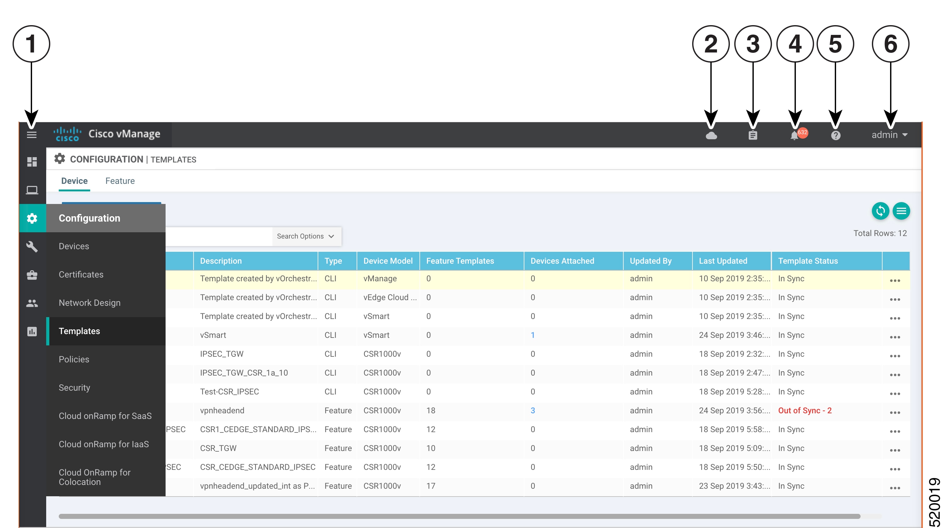
To create a device template:
|
1 |
Menu |
|
2 |
CloudExpress |
|
3 |
Tasks |
|
4 |
Alarms |
|
5 |
Help |
|
6 |
User Profile |
-
In the Device tab, click the Create Template drop-down and select From Feature Template.
-
From the Device Model drop-down, select the type of device for which you are creating the template. vManage NMS displays all the feature templates for that device type. The required feature templates are indicated with an asterisk (*), and the remaining templates are optional. The factory-default template for each feature is selected by default.
-
In the Template Name field, enter a name for the device template. This field is mandatory and can contain only uppercase and lowercase letters, the digits 0 through 9, hyphens (-), and underscores (_). It cannot contain spaces or any other characters.
-
In the Description field, enter a description for the device template. This field is mandatory, and it can contain any characters and spaces.
-
To view the factory-default configuration for a feature template, select the desired feature template and click View Template. Click Cancel to return to the Configuration Template screen.
-
To create a custom template for a feature, select the desired factory-default feature template and click Create Template. The template form is displayed. The top of the form contains fields for naming the template, and the bottom contains fields for defining feature parameters.
-
In the Template Name field, enter a name for the feature template. This field is mandatory and can contain only uppercase and lowercase letters, the digits 0 through 9, hyphens (-), and underscores (_). It cannot contain spaces or any other characters.
-
In the Description field, enter a description for the feature template. This field is mandatory, and it can contain any characters and spaces.
-
For each field, enter the desired value. You may need to click a tab or the plus sign (+) to display additional fields.
-
When you first open a feature template, for each parameter that has a default value, the scope is set to Default (indicated by a check mark), and the default setting or value is shown. To change the default or to enter a value, click the scope drop-down to the left of the parameter field and select one of the following:
|
Parameter Scope |
Scope Description |
|---|---|
|
Device Specific (indicated by a host icon) |
Use a device-specific value for the parameter. For device-specific parameters, you cannot enter a value in the feature template. You enter the value when you attach a device to a device template . When you click Device Specific, the Enter Key box opens. This box displays a key, which is a unique string that identifies the parameter in a CSV file that you create. This file is an Excel spreadsheet that contains one column for each key. The header row contains the key names (one key per column), and each row after that corresponds to a device and defines the values of the keys for that device. You upload the CSV file when you attach a device to a device template. For more information, see Use Variable Values in Configuration Templates. To change the default key, type a new string and move the cursor out of the Enter Key box. Examples of device-specific parameters are system IP address, hostname, GPS location, and site ID. |
|
Global (indicated by a globe icon) |
Enter a value for the parameter, and apply that value to all devices. Examples of parameters that you might apply globally to a group of devices are DNS server, syslog server, and interface MTUs. |
-
For some groups of parameters, you can mark the entire group as device-specific. To do this, click the Mark as Optional Row box. These parameters are then grayed out so that you cannot enter a value for them in the feature template. You enter the value or values when you attach a device to a device template.
-
Click Save.
-
Repeat Steps 7 through 13 to create a custom template for each additional software feature. For details on creating specific feature templates, see the templates listed in Available Feature Templates.
-
Click Create. The new configuration template is displayed in the Device Template table. The Feature Templates column shows the number of feature templates that are included in the device template, and the Type column shows "Feature" to indicate that the device template was created from a collection of feature templates.
Another way to create device templates from feature templates is to first create one or more custom feature templates and then create device templates. You can create multiple feature templates for the same feature. For a list of feature templates, see Available Feature Templates .
-
From the Templates title bar, select Feature.
-
Click the Add Template button.
-
In the left pane, from Select Devices, select the type of device for which you are creating a template. You can create a single feature template for features that are available on multiple device types. You must, however, create separate feature templates for software features that are available only on the device type you are configuring.
-
In the right pane, select the feature template. The template form is displayed. The top of the form contains fields for naming the template, and the bottom contains fields for defining required parameters. If the feature has optional parameters, the bottom of the template form shows a plus sign (+) after the required parameters.
-
In the Template Name field, enter a name for the feature template. This field is mandatory and can contain only uppercase and lowercase letters, the digits 0 through 9, hyphens (-), and underscores (_). It cannot contain spaces or any other characters.
-
In the Description field, enter a description for the feature template. This field is mandatory, and it can contain any characters and spaces.
-
For each required parameter, choose the desired value, and if applicable, select the scope of the parameter. Select the scope from the drop-down menu to the left of each parameter's value box
-
Click the plus sign (+) below the required parameters to set the values of optional parameters.
-
Click Save.
-
Repeat Steps 2 to 9 for each additional feature template you wish to create.
-
From the Templates title bar, select Device.
-
Click the Create Template drop-down and select From Feature Template.
-
From the Device Model drop-down, select the type of device for which you are creating the device template. vManage NMS displays the feature templates for the device type you selected. The required feature templates are indicated with an asterisk (*). The remaining templates are optional.
-
In the Template Name field, enter a name for the device template. This field is mandatory and can contain only uppercase and lowercase letters, the digits 0 through 9, hyphens (-), and underscores (_). It cannot contain spaces or any other characters.
-
In the Description field, enter a description for the device template. This field is mandatory, and it can contain any characters and spaces.
-
To view the factory-default configuration for a feature template, select the desired feature template and click View Template. Click Cancel to return to the Configuration Template screen.
-
To use the factory-default configuration, click Create to create the device template. The new device template is displayed in the Device Template table. The Feature Templates column shows the number of feature templates that are included in the device template, and the Type column shows "Feature" to indicate that the device template was created from a collection of feature templates.
-
To modify the factory-default configuration, select the feature template for which you do not wish to use the factory-default template. From the drop-down list of available feature templates, select a feature template that you created.
-
Repeat Step 18 for each factory-default feature template you wish to modify.
-
Click Create. The new configuration template is displayed in the Device Template table. The Feature Templates column shows the number of feature templates that are included in the device template, and the Type column shows "Feature" to indicate that the device template was created from a collection of feature templates.
Create a Device CLI Template
To create a device template by entering a CLI text-style configuration directly on the Cisco vManage:
-
In the Device tab, click the Create Template drop-down and select CLI Template.
-
From the Device Type drop-down, select the type of device for which you are creating the template.
-
In the Template Name field, enter a name for the device template. This field is mandatory and can contain only uppercase and lowercase letters, the digits 0 through 9, hyphens (–), and underscores (_). It cannot contain spaces or any other characters.
-
In the Description field, enter a description for the device template. This field is mandatory, and it can contain any characters and spaces.
-
In the CLI Configuration box, enter the configuration either by typing it, cutting and pasting it, or uploading a file.
-
To convert an actual configuration value to a variable, select the value and click Create Variable. Enter the variable name, and click Create Variable. You can also type the variable name directly, in the format {{variable-name}}; for example, {{hostname}}.
-
Click Add. The new device template is displayed in the Device Template table. The Feature Templates column shows the number of feature templates that are included in the device template, and the Type column shows "CLI" to indicate that the device template was created from CLI text.
Configure GPS Using Cisco vManage
Use the GPS template for all Cisco cellular routers running Cisco SD-WANsoftware.
For Cisco devices running Cisco SD-WAN software, you can configure the GPS and National Marine Electronics Association (NMEA) streaming. You enable both these features to allow 4G LTE routers to obtain GPS coordinates.
Navigate to the Template Screen and Name the Template
-
In Cisco vManage NMS, select the screen.
-
In the Device tab, click Create Template.
-
From the Create Template drop-down, select From Feature Template.
-
From the Device Model drop-down, select the type of device for which you are creating the template.
-
Select the Cellular tab.
-
In Additional Cellular Controller Templates, click GPS.
-
To create a custom template for GPS, click the GPS drop-down and and then click Create Template. The GPS template form is displayed. The top of the form contains fields for naming the template, and the bottom contains fields for defining GPS parameters.
-
In the Template Name field, enter a name for the template. The name can be up to 128 characters and can contain only alphanumeric characters.
-
In the Template Description field, enter a description of the template. The description can be up to 2048 characters and can contain only alphanumeric characters.
When you first open a feature template, for each parameter that has a default value, the scope is set to Default (indicated by a check mark), and the default setting or value is shown. To change the default or to enter a value, click the scope drop-down to the left of the parameter field and select either Device Specific or Global.
Configure GPS
To configure GPS parameters for the cellular router, configure the following parameters. Parameters marked with an asterisk are required to configure the GPS feature.
|
Parameter Name |
Description |
|---|---|
|
GPS |
Click On to enable the GPS feature on the router. |
|
GPS Mode |
Select the GPS mode:
|
|
NMEA |
Click On to enable the use of NMEA streams to help in determining position. NMEA streams data from the router's 4G LTE NIM to any marine device, such as a Windows-based PC, that is running a commercially available GPS-based application. |
|
Source Address |
Enter the IP address of the interface that connects to the router's NIM. |
|
Destination Address |
Enter the IP address of the marine NMEA server. |
|
Destination Port |
Enter the number of the port to use to send NMEA data to the server. |
To save the feature template, click Save.
Release Information
Introduced in Cisco vManage Release 18.1.1.
Configure On-Demand Tunnels Using Cisco vManage
|
Feature Name |
Release Information |
Description |
|---|---|---|
|
Dynamic On-Demand Tunnels |
Cisco IOS XE Release 17.3.1a Cisco vManage Release 20.3.1 |
You can configure on-demand tunnels between any two Cisco SD-WAN spoke devices. These tunnels are triggered to be set up only when there is traffic between the two devices. |
Note |
|
On the spoke devices, enable on-demand at the system level on all VPN-0 transport interfaces. In the case of multi-homed sites, enable on-demand on all systems in the site.
-
In Cisco vManage, open Configuration > Templates.
-
Click the Feature tab.
-
Click Add Template.
-
Select a platform.
-
In the Basic Information section, select System.
-
Click Advanced.
-
Enable On-demand Tunnel.
-
(optional) Configure the On-demand Tunnel Idle Timeout time. The default idle timeout value is 10 minutes. Range: 1 to 65535 minutes
-
Attach the System feature template to the device template for the spoke device.
Configure Port Connectivity for Cloud OnRamp Colocation Cluster
|
Feature Name |
Release Information |
Description |
|---|---|---|
|
Flexible Topologies |
Cisco IOS XE Release 17.3.1a Cisco vManage Release 20.3.1 Cisco NFVIS Release 4.2.1 |
You can configure the Stackwise Virtual Switch Link (SVL) and uplink ports of switches, and Cisco CSP data ports using the Port Connectivity configuration settings of Cloud OnRamp for Colocation cluster . |
Prerequisites
-
When configuring the SVL and uplink ports, ensure that the port numbers you configure on Cisco vManage match the physically cabled ports.
-
Ensure that you assign serial numbers to both the switches. See Create and Activate Clusters.
For more information about SVL and uplink ports, see wiring requirements in the Cisco SD-WAN Cloud OnRamp for Colocation Solution Guide.
To configure the SVL and uplink ports:
Note |
Before configuring the SVL and uplink ports using the Cluster Topology screen, ensure that you create a Cloud OnRamp for Colocation cluster. See Create and Activate Clusters. |
In the Cluster Topology screen, click Add next to Port Connectivity. In the Port Connectivity configuration window, both the configured switches appear. Hover over a switch port to view the port number and the port type.
Before you change the default port number and port type, note the following information about Cisco Catalyst 9500-40X and Cisco Catalyst 9500-48Y4C switches:
-
The following are the default SVL and uplink ports of Cisco Catalyst 9500 switches.
Cisco Catalyst 9500-40X
-
Stackwise Virtual Switch Link (SVL) ports: 1/0/38-1/0/40, and 2/0/38-2/0/40
-
Uplink ports: 1/0/36, 2/0/36 (input VLAN handoff) and 1/0/37, 2/0/37 (output VLAN handoff)
-
-
Cisco Catalyst 9500-48Y4C
-
SVL ports: 1/0/46-1/0/48, and 2/0/46-2/0/48
-
Uplink ports: 1/0/44, 2/0/44 (input VLAN handoff) and 1/0/45, 2/0/45 (output VLAN handoff) for 10G/25G throughput.
-
-
I, E, and S represent the ingress, egress, and SVL ports.
-
If the physical cabling is same as the default configuration, click Save.
To change the default ports when the connectivity is different for SVL or uplink ports, perform the following:
-
If both the switches are using the same ports:
-
Click a port on a switch that corresponds to a physically connected port.
-
To add the port configuration to the other switch, check the Apply change check box.
If both the switches are not using the same ports:
-
Click a port on Switch1.
-
Choose a port type from Port Type drop-down list.
-
Click a port on Switch2 and then choose the port type.
-
-
To add another port, repeat step 1.
-
Click Save
-
To edit port connectivity information, in the Cluster Topology screen, click Edit next to Port Connectivity.
Note
You can modify the SVL and uplink ports of a cluster when the cluster has not been activated.
-
To reset the ports to default settings, click Reset.
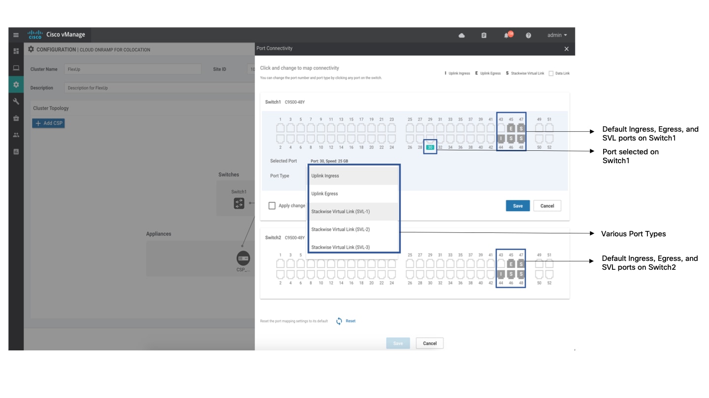
The remaining ports (SR-IOV and OVS) on the Cisco CSP devices and the connections with switches are automatically discovered using Link Layer Discovery Protocol (LLDP) when you activate a cluster. You don't need to configure those ports.
Cisco Colo Manager (CCM) discovers switch neighbor ports and identifies whether all Niantic and Fortville ports are connected. If any port is not connected, CCM sends notifications to Cisco vManage that you can view in the task view window.
Configure Unified Communications
|
Feature Name |
Release Information |
Description |
|---|---|---|
|
Integration with Cisco Unified Communications |
Cisco IOS XE Release 17.3.1a Cisco vManage Release 20.3.1 |
You can configure items for UC voice services from the Feature tab and the Voice Policy page for a supported device. |
Add a Voice Card Feature Template
A voice card feature template configures analog and PRI ISDN digital interfaces, which provide configuration settings for ports on voice cards in routers.
When you add a voice card feature template, for an analog interface, you configure the type of voice card you are configuring, port information for the card, and parameters for the service that you receive from your service provider. For a digital interface, you configure the type of voice card, the T1 or E1 controller, and related parameters.
When you add a module for a voice card, Cisco vManage assists you with the placement of the module by displaying available slots and sub-slots for the module. Cisco vManage determines the available slots and sub-slots based on the device model.
The following table describes options for configuring an analog interface.
|
Option |
Description |
Cisco IOS CLI Equivalent |
|---|---|---|
|
Module |
Select the type of voice module that is installed in the router. |
— |
|
Module Slot/Sub-slot |
Enter the slot and sub-slot of the voice module. |
voice-card slot/subslot |
|
Use DSP |
Enable this option if you want to use the built-in DSPs on the network interface module for TDM calls. |
no local-bypass |
|
Port Type |
Select the type of ports on the voice module that you are configuring for this interface (FXS or FXO). You can select All to define the port type for all ports of the selected type, or Port Range to define the port type for a specified range of ports. Using Port Range, you can create analog interfaces as described later in this procedure to configure different ranges of ports. |
— |
|
Description |
Enter a description of the selected port or ports. For example, fax machine or paging system. |
description string |
|
Secondary Dialtone |
Available if you select FXO from the Port Type drop-down list. Set to On if you want the selected ports to generate a secondary dial tone when callers access an outside line. |
secondary dialtone |
|
Connection PLAR |
Enter the Private Line Automatic Ringdown extension to which the selected ports forward inbound calls. |
connection plar digits |
|
OPX |
Available if you select FXO from the Port Type drop-down list. Check this option if you want to enable Off-Premises Extension for the PLAR extension. |
connection plar opx digits |
|
Signal Type |
Select the Signal Type that indicates an on-hook or off-hook condition for calls that the ports receive. Options are Loopstart, Groundstart, or DID. The DID option is available if you select FXS from the Port Type drop-down list. |
signal {groundstart | loopstart} signal did {delay-dial | immediate | wink-start} |
|
Caller-ID Enable |
Available if you select a signal type of Loopstart or Groundstart. Set to ON if you want to enable caller ID information for inbound calls. |
caller-id enable |
|
DID Signal Mode |
Available if you select a signal type of DID. Choose the mode for the DID signal type (Delay Dial, Immediate, or Wink Start). Default: Wink Start. |
signal did {delay-dial | immediate | wink-start} |
|
Shutdown |
Set to ON if you want to shut down ports that are not being used. Default: Off. |
shutdown |
The following table describes options for configuring a digital interface.
|
Option |
Description |
Cisco IOS CLI Equivalent |
|---|---|---|
|
Digital Interface Tab Provides options for configuring parameters for a T1/E1 voice module and the clock source for the module ports. Before you configure these options, ensure that you have the appropriate DSP module installed for each T1/E1 voice module. |
||
|
Module |
Select the type of T1/E1 voice module that is installed in the router. |
— |
|
Interface Type |
Select the type of interface on the voice module:
|
card type {t1 | e1} slot sub-slot |
|
Slot/Sub-slot |
Enter the slot and sub-slot of the voice module. |
voice-card slot/sub-slot |
|
Use DSP |
Enable this option if you want to use the built-in DSPs on the network interface module for TDM calls. |
no local-bypass |
|
Interface |
Perform these actions to configure the number of T1/E1 ports to be provisioned on the module, and the clock source for each port:
|
controller {t1 | e1} slot/sub-slot/number clock source {network | line | line primary | line secondary} |
|
Network Participation |
This check box displays after you add an interface. Check this check box to configure the T1/E1 module to participate in the backplane clock. Uncheck this check box to remove the clock synchronization with the backplane clock for the module. By defult, this check box is checked. |
network-clock synchronization participate slot/sub-slot |
|
Shutdown |
Perform these actions to disable or enable the controller, serial interface, or voice port that is associated with the interface port.
|
controller e1/t1 slot/sub-slot/port shutdown interface serial slot/sub-slot/port:{ 15 | 23} shutdown voice-port slot/sub-slot/port:{ 15 | 23} shutdown |
|
Time Slots |
Select the number of time slots of the interface type. Valid ranges:
|
controller e1/t1 slot/sub-slot/port pri-group timeslots timeslot-range [voice-dsp] |
|
Framing |
Select the frame type for the interface type. For a T1 PRI interface type, options are:
For an E1 PRI interface type, options are:
|
controller t1 slot/sub-slot/port framing [esf | sf] controller e1 slot/sub-slot/port framing [crc4 | no-crc4] [australia] |
|
Australia |
This check box displays when you select E1 PRI for the interface type. Check this check box to use the australia framing type. |
controller e1 slot/sub-slot/port framing [crc4 | no-crc4] australia |
|
Line Code |
Select the line code type for the interface type. For a T1 PRI interface type, options are:
For an E1 PRI interface type, options are:
|
controller t1 slot/sub-slot/port linecode [ami | b8zs] controller e1 slot/sub-slot/port linecode [ami | hdb3] |
|
Line Termination |
This check box appears only for an Interface type of E1 PRI. Select the line termination type for the E1 controller:
|
controller e1 slot/sub-slot/port line-termination {75-ohm | 120-ohm} |
|
Cable Length Type |
This check box appears only for an Interface type of T1 PRI. Select the cable length type for the T1 PRI interface type:
|
controller t1 slot/sub-slot/port cablelength {short | long} |
|
Cable Length |
This check box appears only for an interface type of T1 PRI. Select the cable length for the T1 PRI interface type. Use this option to fine-tune the pulse of a signal at the receiver for a T1 cable. The default value is 0db. |
controller t1 slot/sub-slot/port cablelength {[short [110ft | 220ft | 330ft | 440ft | 550ft | 660ft ]] [long [-15db | -22.5db | -7.5db | 0db ]]} |
|
Network Side |
Enable this option to have the device use the standard PRI network-side interface. By default, this option is disabled (set to No). |
interface serial slot/sub-slot/port:{15| 23} isdn protocol-emulate [network| user] |
|
Switch Type |
Select the ISDN switch type for this interface:
|
interface serial slot/sub-slot/port:{15| 23} isdn switch-type [primary-4ess | primary-5ess |primary-dms100 | primary-net5 | primary-ni | primary-ntt | primary-qsig] |
|
ISDN Timer |
Perform these actions to configure the ISDN timers for the interface:
|
interface serial slot/sub-slot/port:{15| 23} isdn timer T200 value isdn timer T203 value isdn timer T301 value isdn timer T303 value isdn timer T306 value isdn timer T309 value isdn timer T310 value isdn timer T321 value |
|
Delay Connect Timer |
Select the duration, in milliseconds, to delay connect a PRI ISDN hairpin call. Valid range: integers 0 through 200. Default: 20. |
voice-port slot/sub-slot/port:{15| 23} timing delay-connect value |
|
Clock Tab Use this tab to configure priority order for the primary and secondary clock sources that you selected for each module. This tab is vailable after you configure a PRI ISDN digital interface and click Add. |
||
|
Clock Priority Sorting |
Configure the priority of up to six clock sources. The drop-down list displays the interface ports for which a primary or secondary clock source is defined and that is configured for network participation. Check a check box to select the port for inclusion in the priority list, and use the Up arrow next to a port to change its priority. The list displays the ports in order of priority, with the port with the highest priority at the top of the list. After you configure the priority, this field displays the selected ports in priority order. We recommend that all ports in the priority list be of the same type, either E1-PRI or T1-PRI. |
network-clock input-source priority controller [t1| e1] slot/sub-slot/port |
|
Automatically Sync |
Select Add to enable network synchronization between all modules and the router. Default: On. |
network-clock synchronization automatic |
|
Wait to restore clock |
Enter the amount of time, in milliseconds, that the router waits before including a primary clock source in the clock selection process. Valid range: 0 through 86400. Default: 300. |
network-clock wait-to-restore milliseconds |
To add a voice card feature template:
-
Choose .
-
In the Feature tab, click Add Template.
-
Select the supported device to which you want to add voice services.
-
In the right pane, select Voice Card from the Unified Communications templates.
-
In the Template Name field, enter a name for the template.
This field may contain uppercase and lowercase letters, digits 0 through 9, hyphens (-), and underscores (_).
-
In the Description field, enter a description for the template.
This field can contain any characters and spaces.
-
To configure an analog interface, click New Analog Interface and configure interface options as described in the "Analog Configuration Options" table.
Beginning with Cisco IOS XE Release 17.3.1a, click the Analog Interface tab in the Interface area to access the New Analog Interface button.
You can add as many analog interfaces as needed, based on the number of interfaces that your module supports.
After you configure each analog interface, click Add.
If any analog interfaces are already configured, they appear in the interfaces table on this page. To edit an existing interface, click its pencil icon in the Action column, edit the options in the window that pops up as described in the "Analog Configuration Options" table, and click Save Changes. To delete an interface, click its trash can icon in the Action column.
-
To configure a PRI ISDN digital interface, in the Interface area, click the Digital Interface tab, click New Digital Interface, and configure interface options as described in the "Digital Interface Configuration Options" table.
Click Add after you configure each PRI ISDN digital interface.
Based on the number of interfaces that your module supports, you can add as many PRI ISDN digital interfaces as needed.
If any digital interfaces are already configured, they appear in the interfaces table on this page. To edit an existing interface, click its pencil icon in the Action column, edit the options in the window that pops up as described in the "Digital Interface Configuration Options" table, and click Save Changes. To delete an interface, click its trash can icon in the Action column.
After you save the interface configuration, you cannot change the module type, interface type, slot or sub-slot, or time slots.
If you want to change time slots, you must delete the interface and create a new one.
If you want to change the module type, interface type, and slot or sub-slot, detach the template from the device, unmap the voice policies that are associated with the interfaces, and delete all interfaces that are associated with the module and slot or sub-slot. Next, push the template to the device, reload the device, and create new required interfaces. Finally, push the new template to the device, and reattach the template to the device.
-
Click Save.
-
(Optional) If you want to configure more analog or PRI ISDN digital interfaces for this template, select , select the Feature tab, select Edit for the template from the More Actions menu, and repeat Step 7 or Step 8 and Step 9.
Add a Call Routing Feature Template
A call routing feature template configures parameters for TDM-SIP trunking, including trusted IP addresses for preventing toll fraud, and a dial plan. A dial plan, made up of dial peers, defines how a router routes traffic to and from voice ports to the PSTN or to another branch.
The following table describes global options for configuring call routing.
|
Option |
Description |
Cisco IOS CLI Equivalent |
|---|---|---|
|
Trusted IPv4 Prefix List |
Enter the IPv4 addresses with which the router can communicate through SIP. Enter each IPv4 address in CIDR format. For example, 10.1.2.3/32. Separate each address with a comma (,). The router does not communicate with other IPv4 addresses, which prevents fraudulent calls being placed through the router. A Trusted IPv4 Prefix is required for TDM to IP calls. |
voice service voip ip address trusted list ipv4 ipv4-address/ipv4-network-mask |
|
Trusted IPv6 Prefix List |
Enter the IPv6 addresses with which the router can communicate through SIP. Separate each IPv6 address with a comma (,). The router does not communicate with other IPv6 addresses, which prevents fraudulent calls being placed through the router. A Trusted IPv6 Prefix is required for TDM to IP calls. |
voice service voip ip address trusted list ipv6 ipv6-prefix//prefix-length |
|
Source Interface |
Enter the name of the source interface from which the router initiates SIP control and media traffic. This information defines how the return/response to this traffic should be sent. |
voice service voip sip bind control source-interface interface-id bind media source-interface interface-id |
The following table describes options for configuring dial peers.
|
Option |
Description |
Cisco IOS CLI Equivalent |
|---|---|---|
|
Voice Dial Peer Tag |
Enter a number to be used to reference the dial peer. |
dial-peer voice number {pots | voip} |
|
Dial Peer Type |
Select the type of dial peer that you are creating (POTS or SIP). |
dial-peer voice number {pots | voip} |
|
Direction |
Select the direction for traffic on this dial peer (Incoming or Outgoing). |
Incoming: dial-peer voice number {pots | voip} incoming called-number string Outgoing: dial-peer voice number {pots | voip} destination-pattern string |
|
Description |
Enter a description of this dial peer. |
description |
|
Numbering Pattern |
Enter a string that the router uses to match incoming calls to the dial peer. Enter the string as an E.164 format regular expression in the form [0-9,A-F#*.?+%()-]*T?. |
Incoming: dial-peer voice number {pots | voip} incoming called-numberstring Outgoing: dial-peer voice number {pots | voip} destination-pattern string |
|
Forward Digits Type |
Available if you select the POTS dial peer type and the Outgoing direction. Select how the dial peer transmits digits in outgoing numbers:
Default: None. |
All: dial-peer voice number pots forward-digits all None: dial-peer voice number pots forward-digits 0 Some: dial-peer voice number pots forward-digits number |
|
Forward Digits |
Available if you select Some for Forward Digits Type. Enter the number of right-most digits in the outgoing number to transmit. For example, if you set this value to 7 and the outgoing number is 1112223333, the dial peer transmits 2223333. |
dial-peer voice number pots forward-digits number |
|
Prefix |
Available if you select the POTS dial peer type and the Outgoing direction. Enter digits to be prepended to the dial string for outgoing calls. |
dial-peer voice number pots prefix string |
|
Transport Protocol |
Available if you select SIP for the Dial Peer Type. Choose the transport protocol (TCP or UDP) for SIP control signaling. |
dial-peer voice number voip session transport {tcp | udp} |
|
Preference |
Available if you select POTS or SIP for the Dial Peer Type. Select an integer from 0 to 10, where the lower the number, the higher the preference. If dial peers have the same match criteria, the system uses the one with the highest preference value. Default: 0 (highest preference). |
dial-peer voice number voip preference value dial-peer voice number pots preference value |
|
Voice Port |
Available if you select the POTS dial peer type. Enter the voice port that the router uses to match calls to the dial peer. For an analog port, enter the port you want. For a digital T1 PRI ISDN port, enter a port with the suffix:23. For a digital E1 PRI ISDN port, enter a port with the suffix :15. For an outgoing dial peer, the router sends calls that match the dial peer to this port. For an incoming dial peer, this port serves as an extra match criterion. The dial peers are matched only if a call comes in on this port. |
dial-peer voice number pots For an analog port: port slot/subslot/port For a digital port: port slot/subslot/port:15 port slot/subslot/port:23 |
|
Destination Address |
Available if you select the SIP dial peer type and the Outgoing direction. Enter the network address of the remote voice gateway to which calls are sent after a local outgoing SIP dial peer is matched. Enter the address in one of these formats:
|
session target {ipv4:destination-address | ipv6:destination-address| sip-server | dns:hostname.domain } |
To add a call routing feature template:
-
Choose .
-
In the Feature tab, click Add Template.
-
Select the supported device to which you want to add call routing features.
-
In the right pane, select Call Routing from the Unified Communications templates.
-
In the Template Name field, enter a name for the template.
This field can contain uppercase and lowercase letters, digits 0 through 9, hyphens (-), and underscores (_).
-
In the Description field, enter a description for the template.
This field can contain any characters and spaces.
-
In the Global tab, configure options as described in the "Global Call Routing Options" table.
-
In the Dial Plan tab, perform one of these actions:
-
To configure a dial peer directly, configure options as described in the "Dial Peer Options" table.
-
To create or edit a dial peer CSV file, click Download Dial Peer List to download the system provided file named Dial-Peers.csv. The first time you download this file, it contains field names but no records. Update this file as needed by using an application such as Microsoft Excel. For detailed information about this file, see Dial Peer CSV File.
-
To import configuration information from a dial peer CSV file that you have created, click Upload Dial Peer List.
You can add as many dial peers as needed. Click Add after you configure each dial peer.
If any dial peers already are configured, they appear in the dial peers table on this page. To edit a configured dial peer, click its pencil icon in the Action column, edit the options in the window that pops up as described in the following table, and click Save Changes.To delete a dial peer, click its trash can icon in the Action column.
-
-
Click Save.
Add an SRST Feature Template
An SRST feature template configures parameters for Cisco Unified Survivable Remote Site Telephony (SRST) for SIP. With Cisco Unified SRST, if the WAN goes down or is degraded, SIP IP phones in a branch site can register to the local gateway so that they continue to function for emergency services without requiring WAN resources that are no longer available.
The following table describes global options for configuring Cisco Unified SRST.
|
Option |
Description |
Cisco IOS CLI Equivalent |
|---|---|---|
|
System Message |
Enter a message that displays on endpoints when Cisco Unified SRST mode is in effect. |
voice register global system message string |
|
Max Phones |
Enter the number of phones that the system can register to the local gateway when in Cisco Unified SRST mode. The available values and the maximum values that you can enter in this field depend on the device that you are configuring. Hover your mouse pointer over the Information icon next to this field to see maximum values for supported devices. |
voice register global max-pool max-voice-register-pools |
|
Max Directory Numbers |
Enter the number of DNs that the gateway supports when in Cisco Unified SRST mode. The available values and the maximum values that you can enter in this field depend on the device that you are configuring. Hover your mouse pointer over the Information icon next to the Max phones to support field to see maximum values for supported devices. |
voice register global max-dn max-directory-numbers |
|
Music on Hold |
Select Yes to play music on hold on endpoints when a caller is on hold when in Cisco Unified SRST mode. Otherwise, select No. |
— |
|
Music on Hold file |
Enter the path and file name of the audio file for music on hold. The file must be in the system flash and must be in .au or .wav format. In addition, the file format must contain 8-bit 8-kHz data, for example, CCITT a-law or u-law data format. |
call-manager-fallback moh filename |
The following table describes options for configuring Cisco Unified SRST phone profiles.
|
Option |
Description |
Cisco IOS CLI Equivalent |
|---|---|---|
|
Voice Register Pool Tag |
Enter the unique sequence number of the IP phone to be configured. The maximum value is defined by the Max phones to support option in the Global tab of the SRST feature template. |
voice register pool pool-tag |
|
Device Network IPv6 Prefix |
Enter the IPv6 prefix of the network that contains the IP phone to support. For example, a.b.c.d/24. |
voice register pool pool-tag id [network address mask mask] |
|
Device Network IPv4 Prefix |
Enter the IPv4 prefix of the network that contains the IP phone to support. |
voice register pool pool-tag id [network address mask mask] |
To add an SRST feature template:
-
Choose .
-
In the Feature tab, click Add Template.
-
Select the supported device to which you want to add Cisco Unified SRST features.
-
In the right pane, select SRST from the Unified Communications templates.
-
In the Template Name field, enter a name for the template.
This field can contain uppercase and lowercase letters, digits 0 through 9, hyphens (-), and underscores (_).
-
In the Description field, enter a description for the template.
This field can contain any characters and spaces.
-
In the Global Settings tab, configure options as described in the "Global SRST Options" table.
-
In the Phone Profile tab, click New Phone Profile to create a phone profile, and configure options as described in the "SRST Phone Profile Options" table.
A phone profile provides pool tag and device network information for a SIP phone.
You can add as many phone profiles as needed. Click Add after you configure each phone profile.
If any phone profiles already are configured, they appear in the phone profiles table on this page. To edit a configured phone profile, click its pencil icon in the Action column, edit the options in the window that pops up as described in the following table, and click Save Changes. To delete a phone profile, click its trash can icon in the Action column.
-
Click Save.
Add a DSPFarm Feature Template
A DSP farm is a pool of DSP resources on a router. Cisco SD-WAN uses DSP farm resources that are available to Cisco Unified Communications Manager (CUCM) for CUCM controlled transcoding, conferencing (non-secure only), and media termination point (MTP) services. CUCM dynamically invokes these resources as needed in a call path.
A DSPFarm feature template is used to set up and provision a DSP farm. The template supports dedicated DSP modules only. T1/E1 modules are not supported.
When you add a DSPFarm feature template, you configure options for the following items:
-
Media resource modules—DSP modules and their placement on a router. You determine and build DSP farm profiles based on media resource modules.
-
DSP farm profiles—Each profile defines parameters for provisioning a specific DSP farm service type. A profile includes options for provisioning a group of DSP resources that is used for transcoding, conferencing (only non-secure conferencing is supported), or MTP services. A profile is registered to a CUCM so that the CUCM can invoke the resources for a service as needed.
-
SCCP config—Configures a local interface that is used to communicate with up to four CUCM servers, and configures related information that is required to register the DSP farm profiles to CUCM. Also configures one or more CUCM groups, each of which includes up to four CUCM servers that control the DSP farm services that, in turn, are associated with the servers.
When you add a media resource module, Cisco vManage assists you with the placement of the module by displaying available slots and sub-slots for the module. Cisco vManage determines the available slots and sub-slots based on the device model.
The following table describes options for configuring media resources.
|
Option |
Description |
Cisco IOS CLI Equivalent |
|---|---|---|
|
Module |
Select the router resource module to carry DSP resources that are used by DSPFarm profiles. |
— |
|
Slot/sub-slot ID |
Select the slot and sub-slot in which the resource module that you selected resides. |
voice-card slot/subslot dsp service dspfarm |
The following table describes options for configuring DSP farm services.
|
Option |
Description |
Cisco IOS CLI Equivalent |
|---|---|---|
|
Profile Type |
Select the type of DSP farm service that this profile is for. Options are Transcoder, Conference, and MTP |
dspfarm profile profile-identifier { conference | mtp | transcode } |
|
Profile ID |
A system-generated unique identifier for the profile. |
— |
|
Universal |
Available if you select Transcoder for the Profile Type When this check box is unchecked, transcoding is allowed only between the G.711 codec and other codecs. When this check box is checked, transcoding is allowed between codecs of any type. |
dspfarm profile profile-identifier transcode [universal ] |
|
List Codec |
Select the codecs that are available for the DSP farm service that this profile defines. The following codecs are supported. For MTP profile types, you can select one option, or you can select pass-through and one other option. If you want to change a codec, unselect the current codec before selecting a new one.
|
codec codec-name |
|
Conference Maximum Participants |
Available if you select Conference for the Profile Type. Select the maximum number of parties that can participate in a conference bridge (8, 16, or 32). |
maximum conference-participants number |
|
Maximum Sessions |
Available if you select Transcoder or Conference for the Profile Type. Enter the maximum number of sessions that this profile can support. This value depends on the maximum number sessions that can be configured with the DSP resources that are available on the router. These resources are based on the type of modules in the router. To determine these resources, you can use a DSP calculator. |
maximum sessions number |
|
MTP Type |
Available if you select MTP for the Profile Type. Select the way in which the router performs minor MTP translations such as G.711alaw to G.711ulaw, and DTMF conversions. Options are:
|
maximum session {hardware | software } |
|
MTP Maximum Hardware Sessions |
Available if you select Hardware for the MTP type. Select the maximum number of hardware sessions that can be used for MTP translations and conversions. Maximum value: 4000 |
maximum session hardware number |
|
MTP Maximum Software Sessions |
Available if you select Software for the MTP type. Select the maximum number of CPU sessions that can be used for MTP translations and conversions. Maximum value: 6000 |
maximum session software number |
|
Application |
Select the type of application to which the DSP farm services that are provisioned on the device are associated. |
associate application sccp |
|
Shutdown |
Enable this option to take this profile out of service. |
shutdown |
The following table describes options for configuring SCCP.
|
Option |
Description |
Cisco IOS CLI Equivalent |
|---|---|---|
|
CUCM Tab Configure up to 12 CUCM servers to which the profiles that you defined in the Profile tab register. |
||
|
Local Interface |
Enter the local interface that DSP services that are associated with the SCCP application use to register with CUCM. Enter the interface in this format: interface-type/interface-number/port where:
For example: GigabitEthernet0/0/0. |
sccp local interface-type interface-number [port port-number] |
|
Server List - x |
Designate a CUCM server to which the profiles that you defined in the Profile tab register. In the first field, enter the IP address or DNS name of the CUCM server. In the second field, enter a numerical identifier for the CUCM server. Click the Plus Sign icon (+) to configure up to 11 additional servers. To remove a server, click its corresponding Minus Sign icon. (–). |
sccp ccm {ipv4-address | ipv6-address | dns} identifier identifier-number version 7.0+ |
|
CUCM Groups Tab This tab is available when at least one CUCM server is configured in the CUCM tab. Configure a CUCM group, which includes up to 4 CUCM servers that control the DSP farm services that, in turn, are associated with the servers. If any CUCM groups are already configured, they appear in the table in this tab. To edit a configured CUCM group, click its pencil icon in the Action column, edit the options in the window that pops up as described in the following rows, and click Save Changes. To delete a CUCM group, click its trash can icon in the Action column. |
||
|
Add New CUCM Group |
Click to add a new CUCM group. |
sccp ccm group group-id |
|
Server Groups Priority Order |
Select the priority in which the CUCM servers in this CUCM group are used. To do so:
The servers appear in this field in priority order. To remove a server from the group, click its X icon. To change the priority order of servers, remove the servers and add them back in the desired order. |
associate ccm cucm-id priority priority |
|
CUCM Media Resource Name Profile to be Associated |
In the CUCM Media Resource Name field, enter a unique name that is used to register a DSP farm profile to the CUCM servers. The name must contain from 6 to 15 characters. Characters can be letter, numbers, slashes (/), hyphens (-), and underscores (_). Space characters are not allowed. In the corresponding Profile to be Associated field, select a DSP farm profile to be registered to this CUCM group using the name that you entered. To select a profile, click this field to display a list of the profile IDs that were configured on the Profile tab, and click the ID of the profile that you want. To add another CUCM media resource name and profile, click the plus sign (+). You can add up to 4 CUCM media resources and profiles. To remove a CUCM media resource name and profile, click its corresponding minus sign (–). |
associate ccm profile-identifier register device-name |
|
CUCM Switchback |
Select the switchback method that the CUCM servers in this CUCM group use to switch back after a failover:
Default: graceful. |
switchback method {graceful | guard [timeout-guard-value] | immediate} |
|
CUCM Switchover |
Select the switchover method that CUCM servers in this CUCM use group when failing over:
Default: graceful. |
switchover method {graceful | immediate} |
To add a DSPFarm feature template:
-
Choose .
-
In the Feature tab, click Add Template.
-
Select the supported device to which you want to add a DSP farm.
-
In the right pane, select DSPFarm from the Unified Communications templates.
-
In the Template Name field, enter a name for the template.
This field can contain uppercase and lowercase letters, digits 0 through 9, hyphens (-), and underscores (_).
-
In the Description field, enter a description for the template.
This field can contain any characters and spaces.
-
In the Media Resources Modules tab, click Add Media Resources, and configure options as described in the "Media Resource Options" table.
A media resource module is a DSP module that is used by DSP Farm profiles.
You can add as many media resources interfaces as needed.
Click Add after you configure each media resource. After you configure a media resource, you cannot modify or delete it because other configuration items are based on the module and its placement. If you need to change a media resource configuration, you must remove the DSPFarm feature template and create a new one.
If any media resources are already configured, they appear in the table in this tab. To edit a configured media resource, click its pencil icon in the Action column, edit the options in the window that pops up as described in the "Media Resource Options" table, and click Save Changes. To delete a media resource, click its trash can icon in the Action column.
-
In the Profile tab, click Add New Profile to add a profile for a DSP farm service on a router, and configure options for the profile as described in the "DSP Farm Service Options" table.
Click Add after you configure a profile. You can add up to 10 DSP farm profiles for each feature template.
Before you create a profile, you must know the maximum number of sessions that can be configured with the DSP resources that are available on the router. These resources are based on the type of modules in the router. To determine these resources, you can use a DSP calculator.
After you add a profile, you can modify the List Codec, Maximum Sessions, Maximum Conference Participants, and Shutdown options. You cannot change the profile type. If you want to change the profile type, you must delete the profile and create a new one.
If any profiles are already configured, they appear in the table in this tab. To edit a configured profile, click its pencil icon in the Action column, edit the options in the window that pops up as described in the "DSP Farm Service Options" table, and click Save Changes. To delete a profile, click its trash can icon in the Action column.
-
In the SCCP Config tab, configure options as described in the "SCCP Options" table.
-
Click Save.
Add a Voice Policy
A voice policy defines how the system augments and manipulates calls for various endpoint types. Endpoints include voice ports, POTS dial peers, SIP dial peers, and Cisco Unified SRST phone profiles. A voice policy includes subpolicies for each endpoint that you want to configure.
To add a voice policy:
-
Choose .
-
Click Add Voice Policy.
-
In the Voice Policy Name field, enter a name for the policy.
-
Configure options in the following tabs in the left pane as needed:
-
Voice Ports tab–See Configure Voice Ports for a Voice Policy
-
POTS Dial Peers tab–See Configure POTS Dial Peers for a Voice Policy
-
SIP Dial Peers tab–See Configure SIP Dial Peers for a Voice Policy
-
SRST Phones tab–Configure SRST Phones for a Voice Policy
-
-
Click Save Policy.
Configure Voice Ports for a Voice Policy
When you configure voice ports for a voice policy, you configure options that define how the system augments and manipulates calls for the voice port endpoint type.
You can configure the following call functionality policy options, depending on the type of voice card you are using:
-
Trunk Group— Use these options to configure voice ports as a member of a trunk group for the card. You can configure one trunk group for voice card. The following table describes these options.
Table 22. Trunk Group Options for Voice Ports Option
Description
Cisco IOS CLI Equivalent
Add New Trunk Group
Click to add a trunk group for the selected card.
You can add one trunk group for a voice port.
—
Copy from Existing
Click to copy an existing trunk group to a new trunk group. In the box that appears, change the name if desired, select a trunk group, and click Copy.
—
Name
Name of the trunk group.
The name can contain up to 32 characters.
trunk group name
Hunt-Scheme
Select the hunt scheme in the trunk group for outgoing calls:
-
least-idle both—Searches for an idle channel with the shortest idle time
-
least-idle even—Searches for an idle even-numbered channel with the shortest idle time
-
least-idle odd—Searches for an idle odd-numbered channel with the shortest idle time
-
least-used both—Searches for a trunk group member that has the highest number of available channels (applies only to PRI ISDN cards)
-
least-used even—Searches for a trunk group member that has the highest number of available even-numbered channels (applies only to PRI ISDN cards)
-
least-used odd—Searches for a trunk group member that has the highest number of available odd-numbered channels (applies only to PRI ISDN cards)
-
longest-idle both—Searches for an idle odd-numbered channel with the longest idle time
-
longest-idle even—Searches for an idle channel that has the highest number of available even-numbered channels
-
longest-idle odd—Searches for an idle channel that has the highest number of available odd-numbered channels
-
round-robin both—Searches trunk group members in turn for an idle channel, starting with the trunk group member that follows the last used member
-
round-robin even—Searches trunk group member in turn for an idle even-numbered channel, starting with the trunk group member that follows the last used member
-
round-robin odd—Searches trunk group member in turn for an idle odd-numbered channel, starting with the trunk group member that follows the last used member
-
sequential-both—Searches for an idle channel, starting with the trunk group member with the highest preference within the trunk group
-
sequential-even—Searches for an idle even-numbered channel, starting with the trunk group member with the highest preference within the trunk group
-
sequential-odd—Searches for an idle odd-numbered channel, starting with the trunk group member with the highest preference within the trunk group
-
random—Searches for a trunk group member at random and selects a channel from the member at random
Default: least-used both
trunk group name
hunt-scheme least-idle [both | even | odd ]
hunt-scheme least-used [both | even | odd ]
hunt-scheme longest-idle [both | even | odd ]
hunt-scheme round-robin [both | even | odd ]
hunt-scheme sequential [both | even | odd ]
hunt-scheme random
Max Calls
Enter the maximum number of calls that are allowed for the trunk group. If you do not enter a value, there is no limit on the number of calls.
If the maximum number of calls is reached, the trunk group becomes unavailable for more calls.
-
In field—Enter the maximum number of incoming calls that are allowed for this trunk group
-
Out field— Enter the maximum number of outgoing calls that are allowed for this trunk group
Valid range for both fields: integers 0 through 1000.
trunk group name
max-calls voice number-of-calls direction [ in | out]
Max-Retry
Select the maximum number of outgoing call attempts that the trunk group makes if an outgoing call fails.
If you do not enter a value and a call fails, the system does not attempt to make the call again.
Valid range: integers 1 through 5.
trunk group name
max-retry attempts
Save Trunk Group
Click to save the Trunk Group that you configured.
—
-
-
Translation Profile—Use these options to configure translation rules for calling and called numbers. The following table describes these options.
Table 23. Translation Profile Options for Calling and Called Numbers Option
Description
Cisco IOS CLI Equivalent
Add New Translation Profile
Click to add a translation profile for the selected card.
You can create up to two translation profiles for this endpoint.
voice translation-profile name
Copy from Existing
Click to copy an existing translation profile to a new translation profile. In the box that appears, change the name if desired, select a called translation rule and a calling translation rule, and click Copy.
—
Calling
Click to configure translation rules for the number that is calling in.
The Translation Rules pane displays.
translate calling translation-rule-number
Called
Click to configure translation rules for the number that is being called.
The Translation Rules pane displays.
translate called translation-rule-number
Translation Rules pane
-
Click Add New to create a translation rule.
Alternatively, you can click Copy From Existing to copy an existing translation rule to a new translation rule. In the box that appears, change the name if desired, select a called translation rule and a calling translation rule, and click Copy.
-
In the Translation Rule Number field, enter a unique number that designates the precedence for this rule. Valid range: integers 1 through 100.
-
(Optional) To copy existing translation rules from a CSV file, click Import. Continue to add rules or click Finish. For detailed information about this file, see Translation Rules CSV File.
-
Click Add Rule.
-
In the Match field, enter the string that you want the translation rule to affect. Enter the string in regular expression format beginning and ending with a slash (/). For example, /^9/.
-
From the Action drop-down list, select the action that the system performs for calls that match the string in the Match field. The Reject option causes the system to reject the call. The Replace option causes the system to replace the match number with a value that you specify.
-
If you select the Replace action, in the Replace field that displays, enter the string to which to translate the matched string. Enter the number in regular expression format beginning and ending with a slash (/). For example, //, which indicates a replacement of no string.
As an example, if you specify a match string of /^9/ and a replace string of //, the system removes the leading 9 from calls with a number that begins with 9. In this case, the system translates 914085551212 to 14085551212.
-
Click Save.
-
Add more translation rules as needed.
-
(Optional) Click Export to save the translation rules that you created in a CSV file.
-
Click Finish at the bottom of the pane.
voice translation-rule number
Match and Replace Rule:
rule precedence /match-pattern/ / replace-pattern/
Reject Rule:
rule precedence reject /match-pattern/
-
-
Station ID—Use these options to configure the name and number for caller ID display. The following table describes these options.
Table 24. Station ID Options Option
Description
Cisco IOS CLI Equivalent
Station Name
Enter the name of the station.
The station name can contain up to 50 letters, numbers, and spaces, dashes (-), and underscores (_).
station-id name name
Station Number
Enter the phone number of the station in E.164 format.
The station number can contain up to 15 numeric characters.
station-id number number
-
Line Params—Use these options to configure line parameters on the card for voice quality. The following table describes these options.
Table 25. Line Params Options Option
Description
Cisco IOS CLI Equivalent
Gain
Enter the gain, in dB, for voice input.
Valid range: –6 through 14. Default: 0
input gain decibels
Attenuation
Enter the amount of attenuation, in dB, for transmitted voice output.
Valid range: –6 through 14. Default: 3.
output attenuation decibels
Echo Canceller
Select Enable to apply echo cancellation to voice traffic.
By default, this option is enabled.
echo-cancel enable
Voice Activity Detection (VAD)
Select Enable to apply VAD to voice traffic.
By default, this option is enabled.
vad
Compand Type
Select the companding standard to be used to convert between analog and digital signals in PCM systems (U-law or A-law).
Default: U-Law.
compand-type {u-law | a-law}
Impedance
This field does not apply to PRI ISDN cards.
Select the terminating impedance for calls.
Default: 600r.
impedance {600c | 600r 900c | 900r | complex1 | complex2 | complex3 | complex4 | complex5 | complex6}
Call Progress Tone
Select the locale for call progress tones.
cptone locale
-
Tuning Params—Use these options to configure parameters for signaling between voice ports and another instrument. The following table describes these options.
Table 26. Tuning Params Options Option
Description
Cisco IOS CLI Equivalent
Tuning Params Options for FXO Cards Pre Dial Delay
Enter the delay, in seconds, of the delay on the FXO interface between the beginning of the off-hook state and the initiation of DTMF signaling.
Valid range: 0 through 10. Default: 1.
pre-dial-delay seconds
Supervisory Disconnect
Select the type of tone that indicates that a call has been released and that a connection should be disconnected:
-
Anytone—Any tone indicates a supervisory disconnect
-
Signal—A disconnect signal indicates a supervisory disconnect
-
Dualtone—A dual-tone indicates a supervisory disconnect
Default: Signal.
Anytone:
supervisory disconnect anytone
Signal:
supervisory disconnect
Dualtone:
supervisory disconnect dualtone {mid-call | pre-connect}
Dial Type
Select the dialing method for outgoing calls:
-
pulse—Pulse dialer
-
dtmf—Dual-tone multifrequency dialer
-
mf—Multifrequency dialer
Default: dtmf.
dial-type {dtmf | pulse | mf}
Timing Sup-Disconnect
Enter the minimum time, in milliseconds, that is required to ensure that an on-hook indication is intentional and not an electrical transient on the line before a supervisory disconnect occurs (based on power denial signaled by the PSTN or PBX).
Valid range: 50 through 1500. Default: 350.
timing sup-disconnect milliseconds
Battery Reversal
Battery reversal reverses the battery polarity on a PBX when a call connects, then changes the battery polarity back to normal when the far-end disconnects.
Select Answer to configure the port to support answer supervision by detection of battery reversal.
Select Detection Delay to configure the delay time after which the card acknowledges a battery-reversal signal, then enter the delay time in milliseconds. Valid range: 0 through 800. Default: 0 (no delay).
If an FXO port or its peer FXS port does not support battery reversal, do not configure battery reversal options to avoid unpredictable behavior.
battery-reversal [answer]
battery-reversal-detection-delay milliseconds
Timing Hookflash out
Enter the duration, in milliseconds, of hookflash indications that the gateway generates on the FXO interface.
Valid range: 50 through 1550. Default: 400.
timing hookflash-out milliseconds
Timing Guard out
Enter the number of milliseconds after a call disconnects before another outgoing call is allowed.
Valid range: 300 through 3000. Default: 2000.
timing guard-out milliseconds
Tuning Params Options for FXS Cards
Timing Hookflash In
Enter the minimum and maximum duration, in milliseconds, of an on-hook condition to be interpreted as a hookflash by the FXS card.
Valid range for minimum duration: 0 through 400. Default minimum value: 50.
Valid range for maximum duration: 50 through 1500. Default maximum value: 1000.
timing hookflash-in maximum-milliseconds minimum-milliseconds
Pulse Digit Detection
To enable pulse digit detection at the beginning of a call, select Yes.
Default: Yes.
pulse-digit-detection
Loop Length
Select the length for signaling on FXS ports (Long or Short).
Default: Short.
loop-length [long | short]
Ring
-
Frequency—Select the frequency, in Hz, of the alternating current that, when applied, rings a connected device. Default: 25.
-
DC Offset—Applies only if Loop Length is set to Long. Select the voltage threshold below which a ring does not sound on devices. Valid values: 10-volts, 20-volts, 24-volts, 30-volts, and 35-volts.
ring frequency number
ring dc-offset number
Ringer Equivalence Number (REN)
Select the REN for calls that this card processes. This number specifies the loading effect of a telephone ringer on a line.
Valid range: 1 through 5. Default: 1.
ren number
-
-
Supervisory Disconnect—Use these options to configure parameters for supervisory disconnect events. The following table describes these options.
Table 27. Supervisory Disconnect Options Option
Description
Cisco IOS CLI Equivalent
Add New Supervisory Disconnect
Click to add a supervisory disconnect event.
—
Mode
Choose the mode for the supervisory disconnect event:
-
Custom CPTone—Provides options for configuring cptone detection parameters for a supervisory disconnect event
-
Dual Tone Detection Params— Provides options for configuring dual-tone detection parameters for a supervisory disconnect event
voice class custom-cptone cptone-name
voice class dualtone-detect-params tag
Supervisory Name
Applies to Custom CPTone mode. Enter a name for the supervisory disconnect event.
The name can contain up to 32 characters. Valid characters are letters, numbers, dashes (-), and underscores (_).
voice class custom-cptone cptone-name
Dualtone
Applies to Custom CPTone mode. Select the type of dual-tone that causes a disconnect. Options are:
-
Busy
-
Disconnect
-
Number Unobtainable
-
Out of Service
-
Reorder
-
Ringback
dualtone {ringback |busy | reorder | out-of-service | number-unobtainable | disconnect}
Cadence
Applies to Custom CPTone mode. Enter the cadence interval, in milliseconds, of the dual-tones that cause a disconnect. Enter the cadence as an on/off value pair, separated with a space. You can enter up to 4 on/off value pairs, separated with a space.
cadence cycle-1-on-time cycle-1-off-time [cycle-2-on-time cycle-2-off-time [cycle-3-on-time cycle-3-off-time [ cycle-4-on-time cycle-4-off-time ]]]
Dualtone Frequency
Applies to Custom CPTone mode. Enter the frequency, in Hz, of each tone in the dual-tone.
Valid range for each tone is 300 through 3600.
frequency frequency-1 [frequency-2]
Supervisory Number
Applies to Custom Dual Tone Detection Params mode.
Enter a unique number to identify dual-tone detection parameters.
Valid range: 1 through 10000.
voice class dualtone-detect-params tag-number
Cadence-Variation
Applies to Custom Dual Tone Detection Params mode. Enter the maximum time, in milliseconds, by which the tone onset can vary from the onset time and still be detected. The system multiplies the value that you enter by 10.
Valid range: 0 through 200 in units of 10. Default: 10.
cadence-variation time
Frequency
Applies to Custom Dual Tone Detection Params mode.
-
Max Delay—Enter the maximum delay, in milliseconds, before a supervisory disconnect is performed after the dual-tone is detected. The system multiplies the value that you enter by 10. Valid range: 0 through 100 in units of 10. Default: 10.
-
Max Deviation—Enter the maximum deviation, in Hz, by which each tone can deviate from configured frequencies and be detected. Valid range: 10 through 125. Default: 10.
-
Max Power—Enter the power of the dual-tone, in dBm0, above which a supervisory disconnect is no detected. Valid range: 0 through 20. Default: 10.
-
Min Power— Enter the power of the dual-tone, in dBm0, below which a supervisory disconnect is not detected. Valid range: 10 through 35. Default: 30.
-
Power Twist—Enter difference, in dBm0, between the minimum power and the maximum power of the dual-tone above which a supervisory disconnect is not detected. Valid range: 0 through 15. Default: 6.
freq-max-delay time
freq-max-deviation hertz
freq-max-power dBm0
freq-min-power dBm0
freq-power-twist dBm0
Save
Click to save the supervisory disconnect information that you configured.
—
-
-
DID Timers—Use these options to configure timers for DID calls. The following table describes these options.
Table 28. DID Timers Options Option
Description
Cisco IOS CLI Equivalent
Wait Before Wink
Enter the amount of time, in milliseconds, that the card waits after receiving a call before sending a wink signal to notify the remote side that it can send DNIS information.
Valid range: 100 through 6500. Default: 550.
timing wait-wink milliseconds
Wink Duration
Enter the maximum amount of time, in milliseconds, of the wink signal for the card.
Valid range: 50 through 3000. Default: 200.
timing wait-duration milliseconds
Clear Wait
Enter the minimum amount of time, in milliseconds, between an inactive seizure signal and the call being cleared for the card.
Valid range: 200 through 2000. Default: 400.
timing clear-wait milliseconds
Dial Pulse Min Delay
Enter the amount of time, in milliseconds, between wink-like pulses for the card.
Valid range: 0 or 140 through 5000. Default: 140.
timing dial-pulse min-delay milliseconds
Answer Winkwidth
Enter the minimum delay time, in milliseconds, between the start of an incoming seizure and the wink signal.
Valid range: 110 through 290. Default: 210.
timing answer-winkwidth milliseconds
To configure voice ports for a voice policy, follow these steps:
-
When adding a voice policy from the Configuration > Unified Communications page, select Voice Ports in the left pane.
-
From the Add Voice Ports Policy Profile drop-down list, select Create New.
Alternatively, you can select Copy from Existing to copy an existing voice policy to a new voice policy. In the box that appears, select the name of the policy profile to copy, enter a new name for the profile if desired, and click Copy.
-
Select FXO, FXS, PRI ISDN, or FXS DID to specify the type of voice port that the policy is for.
-
Select the types of call functionality policy options that you want to configure from the list of options that displays, and click Next. These option types include the following:
-
Trunk Group—Available for FXO, FXS, FXS DID, and PRI ISDN cards.
Use these options to configure voice ports as a member of a trunk group for the card.
-
Translation Profile—Available for FXO, FXS, PRI ISDN, and FXS DID cards.
Use these options to configure translation rules for calling and called numbers.
-
Station ID—Available for FXO, FXS, and FXS DID cards.
Use these options to configure the name and number for caller ID display.
-
Line Params—Available for FXO, FXS, PRI ISDN, and FXS DID cards.
Use these options to configure line parameters on the card for voice quality.
-
Tuning Params—Available for FXO and FXS cards.
Use these options to configure parameters for signaling between voice ports and another instrument.
-
Supervisory Disconnect—Available for FXO cards.
Use these options to configure parameters for supervisory disconnect events. These events provide an indication that a call has disconnected.
-
DID Timers—Available for FXS DID cards.
Use these options to configure timers for DID calls.
-
-
In the page that displays, configure as needed the options on the tabs as needed.
The tabs that are available depend on the voice port and call functionality policy option types that you selected.
-
Trunk Group options—For a description of these options, see the "Trunk Group Options for Voice Ports" table.
If any trunk groups are already configured for other voice cards, they appear in the trunk groups table on this page. To edit a configured trunk group, click its pencil icon in the Action column, edit the options in the window that pops up as described in the "Trunk Group Options for Voice Ports" table, and click Save Changes. To delete a trunk group, click its trash can icon in the Action column.
After you click Save Trunk Group when saving trunk group options, configure the priority for a trunk group by double-click the Priority field for a trunk group in the Trunk Group table, entering a priority number, and pressing Enter or clicking outside of the Priority field. Valid priority numbers are integers 1 through 64. The number you enter is the priority of the POTS dial peer in the trunk group for incoming and outgoing calls.
-
Translation Profile options—For a description of these options, see the "Translation Profile Options for Calling and Called Numbers" table.
After you click Finish when configuring translation profile options, perform these actions:
-
Add another translation profile if needed. You can create up to two translation profiles for this endpoint.
-
Click Save Translation Profile.
-
For each translation profile that you create, double-click the dash (-) that displays in Direction column in the table of translation rules and select Incoming or Outgoing from the drop-down list that displays. The Incoming selection applies the corresponding translation rule to traffic that is incoming to this endpoint. The Outgoing selection applies the corresponding translation rule to traffic that is outgoing from this endpoint.
-
-
Station ID options—For a description of these options, see the "Station ID Options" table.
-
Line Params options—For a description of these options, see the "Line Params Options" table.
-
Tuning Params options—For a description of these options, see the "Tuning Params Options" table.
-
Supervisory Disconnect options—For a description of these options, see the "Supervisory Disconnect Options" table.
You can configure as many supervisory disconnect events as needed.
-
DID Timers options—For a description of these options, see the "DID Timers Options" table
-
-
Click Next
-
In the Policy Profile Name field, enter a name for this child policy.
-
In the Policy Profile Description field, enter a description for this child policy.
-
Click Save.
Configure POTS Dial Peers for a Voice Policy
When you configure POTS Dial Peers for a voice policy, you configure options that define how the system augments and manipulates calls for the POTS dial peer endpoint type.
You can configure the following options:
-
Trunk Groups—The following table describes these options.
Table 29. Trunk Group Options for POTS Dial Peers Option
Description
Cisco IOS CLI Equivalent
Add New Trunk Group
Click to add a trunk group for the selected card.
You can add one trunk group for a voice port.
—
Copy from Existing
Click to copy an existing trunk group to a new trunk group. In the box that appears, change the name if desired, select a trunk group, and click Copy.
A trunk group name whose name is preceded with “{Master}” is already associated with this voice policy. When you copy a this type of trunk group, the system reuses the existing trunk group without creating another instance of the trunk group definition. In this case, you cannot change the name.
—
Name
Name of the trunk group.
The name can contain up to 32 characters.
trunk group name
Hunt-Scheme
Select the hunt scheme in the trunk group for outgoing calls:
-
least-idle both—Searches for an idle channel with the shortest idle time
-
least-idle even—Searches for an idle even-numbered channel with the shortest idle time
-
least-idle odd—Searches for an idle odd-numbered channel with the shortest idle time
-
least-used both—Searches for a trunk group member that has the highest number of available channels (applies to only PRI ISDN cards)
-
least-used even—Searches for a trunk group member that has the highest number of available even-numbered channels (applies only to PRI ISDN cards)
-
least-used odd—Searches for a trunk group member that has the highest number of available odd-numbered channels (applies only to PRI ISDN cards)
-
longest-idle both—Searches for an idle odd-numbered channel with the longest idle time
-
longest-idle even—Searches for an idle channel that has the highest number of available even-numbered channels
-
longest-idle odd—Searches for an idle channel that has the highest number of available odd-numbered channels
-
round-robin both—Searches trunk group members in turn for an idle channel, starting with the trunk group member that follows the last used member
-
round-robin even—Searches trunk group member in turn for an idle even-numbered channel, starting with the trunk group member that follows the last used member
-
round-robin odd—Searches trunk group member in turn for an idle odd-numbered channel, starting with the trunk group member that follows the last used member
-
sequential-both—Searches for an idle channel, starting with the trunk group member with the highest preference within the trunk group
-
sequential-even—Searches for an idle even-numbered channel, starting with the trunk group member with the highest preference within the trunk group
-
sequential-odd—Searches for an idle odd-numbered channel, starting with the trunk group member with the highest preference within the trunk group
-
random—Searches for a trunk group member at random and selects a channel from the member at random
Default: least-used both
trunk group name
hunt-scheme least-idle [both | even | odd ]
hunt-scheme least-used [both | even | odd ]
hunt-scheme longest-idle [both | even | odd ]
hunt-scheme round-robin [both | even | odd ]
hunt-scheme sequential [both | even | odd ]
hunt-scheme random
Max Calls
Enter the maximum number of calls that are allowed for the trunk group. If you do not enter a value, there is no limit on the number of calls.
If the maximum number of calls is reached, the trunk group becomes unavailable for more calls.
-
In field—Enter the maximum number of incoming calls that are allowed for this trunk group.
-
Out field— Enter the maximum number of outgoing calls that are allowed for this trunk group.
Valid range for both fields: integers 0 through 1000.
trunk group name
max-calls voice number-of-calls direction [ in | out]
Max-Retry
Select the maximum number of outgoing call attempts that the trunk group makes if an outgoing call fails.
If you do not enter a value and a call fails, the system does not attempt to make the call again.
Valid range: integers 1 through 5.
trunk group name
max-retry attempts
-
-
Translation Profiles—The following table describes these options.
Table 30. Translation Profile Options for POTS Dial Peers Option
Description
Cisco IOS CLI Equivalent
Add New Translation Profile
Click to add a translation profile for the selected POTS dial peer.
You can create up to two translation profiles for this endpoint.
—
Copy from Existing
Click to copy an existing translation profile to a new translation profile. In the box that appears, change the name if desired, select a called translation rule and a calling translation rule, and click Copy.
—
Name
Name of the translation profile.
The name can contain up to 32 characters.
voice translation-profile name
Calling
Click to configure translation rules for the number that is calling in.
The Translation Rules pane displays.
translate calling translation-rule-number
Called
Click to configure translation rules for the number that is being called.
The Translation Rules pane displays.
translate called translation-rule-number
Translation Rules pane
-
Click Add New to create a translation rule.
Alternatively, you can click Copy From Existing to copy an existing translation rule to a new translation rule. In the box that appears, change the name if desired, select a called translation rule and a calling translation rule, and click Copy.
-
In the Translation Rule Number field, enter a unique number that designates the precedence for this rule. Valid range: integers 1 through 100.
-
(Optional) To copy existing translation rules from a CSV file, click Import. Continue to add rules or click Finish. For detailed information about this file, see Translation Rules CSV File.
-
Click Add Rule.
-
In the Match field, enter the string that you want the translation rule to affect. Enter the string in regular expression format beginning and ending with a slash (/). For example, /^9/.
-
From the Action drop-down list, select the action that the system performs for calls that match the string in the Match field. The Reject option causes the system to reject the call. The Replace option causes the system to replace the match number with a value that you specify.
-
If you select the Replace action, in the Replace field that displays, enter the string to which to translate the matched string. Enter the number in regular expression format beginning and ending with a slash (/). For example, //, which indicates a replacement of no string.
As an example, if you specify a match string of /^9/ and a replace string of //, the system removes the leading 9 from calls with a number that begins with 9. In this case, the system translates 914085551212 to 14085551212.
-
Click Save.
-
Add more translation rules as needed.
-
(Optional) Click Export to save the translation rules that you created in a CSV file.
-
Click Finish at the bottom of the pane.
voice translation-rule number
Match and Replace Rule:
rule precedence /match-pattern/ / replace-pattern/
Reject Rule:
rule precedence reject /match-pattern/
-
To configure POTS dial peers for a voice policy:
-
When adding a voice policy from the Configuration > Unified Communications page, select POTS Dial Peer in the left pane.
-
From the Add POTS Dial Peer Policy Profile drop-down list, select Create New.
Alternatively, you can select Copy from Existing to copy an existing POTS dial peer policy to a new one. In the box that appears, select the name of the policy profile to copy, enter a new name for the profile if desired, and click Copy.
-
Select the types of POTS dial peers that you that you want to configure from the list of options that displays, and click next.
Options are Trunk Group (beginning with Cisco IOS XE Release 17.3.1a) and Translation Profile.
-
To configure trunk groups, perform the following actions.
If any trunk groups are already configured, they appear in the trunk groups table on this page. To edit a configured trunk group, click its pencil icon in the Action column, edit the options in the window that pops up as described in the "Trunk Groups for POTS Dial Peers Options" table, and click Save Changes. To delete a trunk group, click its trash can icon in the Action column.
-
Configure trunk group options as described in the "Trunk Groups Options for POTS Dial Peers " table.
-
Add another trunk group if needed.
You can create up to 64 trunk groups for this endpoint.
-
Click Save Trunk Group.
-
Configure the priority for a trunk group by double-click the Priority field for a trunk group in the Trunk Group table, entering a priority number, and pressing Enter or clicking outside of the Priority field. Valid priority numbers are integers 1 through 64. Repeat this process for the other trunk groups in the table. The number you enter is the priority of the POTS dial peer in the trunk group for incoming and outgoing calls.
-
-
To configure translation profiles, perform these actions:
-
Configure translation profile options as described in the "Translation Profile Options for POTS Dial Peers" table.
-
Add another translation profile if needed.
You can create up to two translation profiles for this endpoint.
-
Click Save Translation Profile.
-
For each translation profile that you create, double-click the dash (-) that displays in Direction column in the table of translation rules and select Incoming or Outgoing from the drop-down list that displays.
The Incoming selection applies the corresponding translation rule to traffic that is incoming to this endpoint. The Outgoing selection applies the corresponding translation rule to traffic that is outgoing from this endpoint.
-
-
Click Next.
-
In the Policy Profile Name field, enter a name for this child policy.
-
In the Policy Profile Description field, enter a description for this child policy.
-
Click Save.
Configure SIP Dial Peers for a Voice Policy
When you configure SIP Dial Peers for a voice policy, you configure options that define how the system augments and manipulates calls for the SIP dial peer endpoint type.
You can configure the following options, depending on the policy type for which you are configuring SIP dial peers:
-
Translation Profiles—Use these options to configure translation rules for called and calling numbers on SIP dial peers. The following table describes these options.
Table 31. Translation Profile Options for Calling Numbers on SIP Dial Peers Option
Description
Cisco IOS CLI Equivalent
Add New Translation Profile
Click to add a translation profile for the selected SIP dial peer.
You can create up to two translation profiles for this endpoint.
voice translation-profile name
Copy from Existing
Click to copy an existing translation profile to a new translation profile. In the box that appears, change the name if desired, select a called translation rule and a calling translation rule, and click Copy.
—
Calling
Click to configure translation rules for the number that is calling in.
The Translation Rules pane displays.
translate calling translation-rule-number
Called
Click to configure translation rules for the number that is being called.
The Translation Rules pane displays.
translate called translation-rule-number
Translation Rules pane
-
Click Add New to create a translation rule.
Alternatively, you can click Copy From Existing to copy an existing translation rule to a new translation rule. In the box that appears, change the name if desired, select a called translation rule and a calling translation rule, and click Copy.
-
In the Translation Rule Number field, enter a unique number that designates the precedence for this rule. Valid range: integers 1 through 100.
-
(Optional) To copy existing translation rules from a CSV file, click Import. Continue to add rules or click Finish. For detailed information about this file, see Translation Rules CSV File.
-
Click Add Rule.
-
In the Match field, enter the string that you want the translation rule to affect. Enter the string in regular expression format beginning and ending with a slash (/). For example, /^9/.
-
From the Action drop-down list, select the action that the system performs for calls that match the string in the Match field. The Reject option causes the system to reject the call. The Replace option causes the system to replace the match number with a value that you specify.
-
If you select the Replace action, in the Replace field that displays, enter the string to which to translate the matched string. Enter the number in regular expression format beginning and ending with a slash (/). For example, //, which indicates a replacement of no string.
As an example, if you specify a match string of /^9/ and a replace string of //, the system removes the leading 9 from calls with a number that begins with 9. In this case, the system translates 914085551212 to 14085551212.
-
Click Save.
-
Add more translation rules as needed.
-
(Optional) Click Export to save the translation rules that you created in a CSV file.
-
Click Finish at the bottom of the pane.
voice translation-rule number
Match and Replace Rule:
rule precedence /match-pattern/ / replace-pattern/
Reject Rule:
rule precedence reject /match-pattern/
-
-
Media Profiles—Use these options to configure codecs to be available for the SIP trunk communication with remote dial peers and DTMF relay options to use for SIP calls. The following table describes these options.
Table 32. Media Profile Options Option
Description
Cisco IOS CLI Equivalent
Add New Media Profile
Click to add a translation profile for the dial peer.
—
Copy from Existing
Click to copy an existing media profile to a new media profile. In the box that appears, enter a media profile number for the profile, and click Copy.
—
Media Profile Number
Enter a number for this SIP media profile.
Valid range: Integers 1 through 10000.
voice class codec tag-number
Codec
Move from the Source list to the Target list the codecs that you want to be made available for the SIP trunk to use when communicating with the remote dial peer.
Codecs in the target list are in descending order of priority, with the highest priority at the top of the list. Drag and drop items in this list to rearrange them.
voice class codec tag-number
codec preference value codec-type
DTMF
Move from the Source list to the Target list the DTMF relay options that you want the system to use for SIP calls.
Items in the Target list are in descending order of priority, with the highest priority at the top of the list. Drag and drop items in this list to rearrange them.
If you want to include the Inband option in the Target list, it can be the only option in that list. If you want to include other options in the Target list, move the Inband option to the Source list before saving the media profile.
dtmf-relay {[[sip-notify] [sip-kpml] [rtp-nte]]} Save
Click to save the configuration settings that you made.
—
-
Modem Pass-through—Use these options to configure the modem pass-through feature for a SIP dial peer endpoint. The following table describes these options.
Table 33. Modem Pass-Through Options Option
Description
Cisco IOS CLI Equivalent
Add New Modem Pass-through
Click to add a modem pass-through for this SIP dial peer endpoint.
—
Copy from Existing
Click to copy an existing modem pass-through to a new modem pass-through profile. In the box that appears, select an existing modem pass-through, enter new name if desired, and click Copy.
—
Name
Name of the modem pass-through.
This name is used when you copy an existing modem pass-through profile to a new one.
—
Protocol
Select the protocol for the modem pass-through:
-
None—Modem pass-through is disabled on the device
-
NSE G.711ulaw—Uses named signaling events (NSEs) to communicate G.711ulaw codec switchover between gateways
-
NSE G.711alaw—Uses named signaling events (NSEs) to communicate G.711alaw codec switchover between gateways
None:
no modem passthrough
NSE G.711 ulaw:
modem passthrough nse codec g711ulaw
NSE G.711 alaw:
modem passthrough nse codec g711alaw
Save Modem Pass-Through
Click to save the configuration settings that you made.
—
-
-
Fax Protocol—Use these options to configure the fax protocol capability for a SIP dial peer endpoint. The following table describes these options.
Table 34. Fax Protocol Options Option
Description
Cisco IOS CLI Equivalent
Add New Fax Protocol
Click to add a fax protocol for the dial peer.
—
Copy from Existing
Click to copy an existing fax protocol to a new fax protocol. In the box that appears, select an existing fax protocol, enter new name if desired, and click Copy.
—
Name
Name of the fax protocol.
This name is used when you copy an existing fax profile to a new fax profile.
—
Primary
Select from a set of fax protocol options. Each option is a bundled set of related fax commands.
For a detailed description of each bundle, see the “Primary Fax Protocol Command Bundles” table
The descriptions of the bundles include the following components:
-
nse—Uses NSEs to switch to T.38 fax relay mode
-
force—Unconditionally uses Cisco Network Services Engines (NSE) to switch to T.38 fax relay
-
version—Specifies a version for configuring fax speed:
-
0—Configures version 0, which uses T.38 version 0 (1998–G3 faxing)
-
3—Configures version 3, which uses T.38 version 3 (2004–V.34 or SG3 faxing)
-
-
none—No fax pass-through or T.38 fax relay is attempted
-
Pass-through—The fax stream uses one of the following high-bandwidth codecs:
-
g711ulaw—Uses the G.711 ulaw codec
-
g711alaw—Uses the G.711 alaw codec
-
fax protocol { none | pass-through {g711ulaw | g711alaw} [fallback none ]| t38 [nse [force]] [version {0 | 3}] [ls-redundancy value [hs-redundancy value]] [fallback {none | pass-through {g711ulaw | g711alaw}}]}
Fallback
Available when the primary protocol bundle name that you selected in the Primary field begins with “T.38” or with “Fax Pass-through.”
Select the fallback mode for fax transmissions. This fallback mode is used if the primary fax protocol cannot be negotiated between device endpoints.
For a detailed description of each option, see the "Fallback Protocol Options” table.
fax protocol {none | pass-through {g711ulaw | g711alaw} [fallback none] | t38 [nse [force]] [version {0 | 3}] [ls-redundancy value [hs-redundancy value]] [fallback {none | pass-through {g711ulaw | g711alaw}}]}
Low Speed
Available when the primary protocol bundle name that you selected in the Primary field begins with “T.38.”
Specifies the number of redundant T.38 fax packets to be sent for the low-speed V.21-based T.30 fax machine protocol.
Range: varies from 0 (no redundancy) to 5. Default: 0.
ls-redundancy value
High Speed
Available when the primary protocol bundle name that you selected in the Primary field begins with “T.38.”
Specifies the number of redundant T.38 fax packets to be sent for high-speed V.17, V.27, and V.29 T.4 or T.6 fax machine image data.
Range: varies from 0 (no redundancy) to 2. Default: 0
hs-redundancy value
Save Fax Protocol
Click to save the configuration settings that you made.
—
-
The following table describes the bundled sets of fax commands that are available for the Primary option when you configure the fax protocol capability for a SIP dial peer endpoint.
For low speed (ls) redundancy, the range varies from 0 (no redundancy) to 5. For high speed (HS redundancy, the range varies from 0 (no redundancy) to 2.
|
Fax Command Protocol Bundle |
Description |
Cisco IOS CLI Equivalent |
|---|---|---|
|
T.38 Fax Relay Version 3 |
Primary fax protocol is T.38 fax relay version 3. Options for selecting the low-speed and high-speed redundancy values are available. |
fax protocol t38 version 3 ls-redundancy value hs-redundancy value no fax-relay sg3-to-g3 |
|
T.38 Fax Relay Version 0 |
Primary fax protocol is T.38 fax relay version 0. Options for selecting the low-speed and high-speed redundancy values are available. |
fax protocol t38 version 0 ls-redundancy value hs-redundancy value |
|
T.38 Fax Relay Version 3 NSE |
Primary fax protocol is NSE based T.38 fax relay version 3. Options for selecting the low-speed and high-speed redundancy values are available. |
fax protocol t38 version 3 nse ls-redundancy value hs-redundancy value no fax-relay sg3-to-g3 |
|
T.38 Fax Relay Version 3 NSE force |
Primary fax protocol is NSE force option of T.38 fax relay version 3. Options for selecting the low-speed and high-speed redundancy values are available. |
fax protocol t38 version 3 nse force ls-redundancy value hs-redundancy value no fax-relay sg3-to-g3 |
|
T.38 Fax Relay Version 0 NSE |
Primary fax protocol is NSE option of T.38 fax relay version 0. Options for selecting the low-speed and high-speed redundancy values are available. |
fax protocol t38 version 0 nse ls-redundancy value hs-redundancy value |
|
T.38 Fax Relay Version 0 NSE force |
Primary fax protocol is NSE force option of T.38 fax relay version 0. Options for selecting the low-speed and high-speed redundancy values are available. |
fax protocol t38 version 0 nse force ls-redundancy value hs-redundancy value |
|
T.38 Fax Relay Version 0 No ECM |
Primary fax protocol is T.38 fax relay version 0 with ECM disabled. Options for selecting the low-speed and high-speed redundancy values are available. |
fax protocol t38 version 0 ls-redundancy value hs-redundancy value fax-relay ecm disable |
|
T.38 Fax Relay Version 0 NSE No ECM |
Primary fax protocol is NSE based T.38 fax relay version 0 with ECM disabled. Options for selecting the low-speed and high-speed redundancy values are available. |
fax protocol t38 version 0 nse ls-redundancy value hs-redundancy value fax-relay ecm disable |
|
T.38 Fax Relay Version 0 NSE force No ECM |
Primary fax protocol is NSE force option T.38 fax relay version 0 with ECM disabled. Options for selecting the low-speed and high-speed redundancy values are available. |
fax protocol t38 version 0 nse force ls-redundancy value hs-redundancy value fax-relay ecm disable |
|
T.38 Fax Relay Version 0 Rate 14.4 No ECM |
Primary fax protocol is T.38 fax relay version 0 with ECM disabled and fax rate of 14,400 bps. Options for selecting the low-speed and high-speed redundancy values are available. |
fax protocol t38 version 0 ls-redundancy value hs-redundancy value fax-relay ecm disable fax rate 14400 |
|
T.38 Fax Relay Version 0 NSE Rate 14.4 No ECM |
Primary fax protocol is NSE based T.38 fax relay version 0 with ECM disabled and fax rate of 14,400 bps. Options for selecting the low-speed and high-speed redundancy values are available. |
fax protocol t38 version 0 nse ls-redundancy value hs-redundancy value fax-relay ecm disable fax rate 14400 |
|
T.38 Fax Relay Version 0 NSE force Rate 14.4 No ECM |
Primary fax protocol is NSE force option T.38 fax relay version 0 with ECM disabled and fax rate of 14,400 bps. Options for selecting the low-speed and high-speed redundancy values are available. |
fax protocol t38 version 0 nse force ls-redundancy value hs-redundancy value fax-relay ecm disable fax rate 14400 |
|
T.38 Fax Relay Version 0 Rate 9.6 No ECM |
Primary fax protocol is T.38 fax relay version 0 with ECM disabled and fax rate of 9,600 bps Options for selecting the low-speed and high-speed redundancy values are available. |
fax protocol t38 version 0 ls-redundancy value hs-redundancy value fax-relay ecm disable fax rate 9600 |
|
T.38 Fax Relay Version 0 NSE Rate 9.6 No ECM |
Primary fax protocol is NSE based T.38 fax relay version 0 with ECM disabled and fax rate of 9,600 bps. Options for selecting the low-speed and high-speed redundancy values are available. |
fax protocol t38 version 0 nse ls-redundancy value hs-redundancy value fax-relay ecm disable fax rate 9600 |
|
T.38 Fax Relay Version 0 NSE force Rate 9.6 No ECM |
Primary fax protocol is NSE force option T.38 fax relay version 0 with ECM disabled and fax rate of 9,600 bps. Options for selecting the low-speed and high-speed redundancy values are available. |
fax protocol t38 version 0 nse force ls-redundancy value hs-redundancy value fax-relay ecm disable fax rate 9600 |
|
T.38 Fax Relay Version 0 Rate 14.4 |
Primary fax protocol is T.38 fax relay version 0 with ECM and fax rate of 14,400 bps. Options for selecting the low-speed and high-speed redundancy values are available. |
fax protocol t38 version 0 ls-redundancy value hs-redundancy value fax rate 14400 |
|
T.38 Fax Relay Version 0 NSE Rate 14.4 |
Primary fax protocol is NSE based T.38 fax relay version 0 with ECM and fax rate of 14,400 bps. Options for selecting the low-speed and high-speed redundancy values are available. |
fax protocol t38 version 0 nse ls-redundancy value hs-redundancy value fax rate 14400 |
|
T.38 Fax Relay Version 0 NSE force Rate 14.4 |
Primary fax protocol is NSE force option T.38 fax relay version 0 with ECM and fax rate of 14,400 bps. Options for selecting the low-speed and high-speed redundancy values are available. |
fax protocol t38 version 0 nse force ls-redundancy value hs-redundancy value fax rate 14400 |
|
T.38 Fax Relay Version 0 Rate 9.6 |
Primary fax protocol is T.38 fax relay version 0 with ECM and fax rate of 9,600 bps. Options for selecting the low-speed and high-speed redundancy values are available. |
fax protocol t38 version 0 ls-redundancy value hs-redundancy value fax rate 9600 |
|
T.38 Fax Relay Version 0 NSE Rate 9.6 |
Primary fax protocol is NSE based T.38 fax relay version 0 with ECM and fax rate of 9,600 bps. Options for selecting the low-speed and high-speed redundancy values are available. |
fax protocol t38 version 0 nse ls-redundancy value hs-redundancy value fax rate 9600 |
|
T.38 Fax Relay Version 0 NSE force Rate 9.6 |
Primary fax protocol is NSE force option T.38 fax relay version 0 with ECM and fax rate of 9,600 bps. Options for selecting the low-speed and high-speed redundancy values are available. |
fax protocol t38 version 0 nse force ls-redundancy value hs-redundancy value fax rate 9600 |
|
None |
Fax protocol is disabled. |
fax protocol none |
|
Fax Pass-through G711ulaw |
Primary fax protocol is fax pass-through with pass-through codec set to g711ulaw. |
fax protocol pass-through g711ulaw |
|
Fax Pass-through G711ulaw No ECM |
Primary fax protocol is fax pass-through with pass-through codec set to g711ulaw and ECM disabled. |
fax protocol pass-through g711ulaw fax-relay ecm disable |
|
Fax Pass-through G711alaw |
Primary fax protocol is fax pass-through with pass-through codec set to g711alaw. |
fax protocol pass-through g711alaw |
|
Fax Pass-through G711alaw No ECM |
Primary fax protocol is fax pass-through with pass-through codec set to g711alaw and ECM disabled. |
fax protocol pass-through g711alaw fax-relay ecm disable |
The following table describes the selections that are available for the Fallback option when you configure the fax protocol capability for a SIP dial peer endpoint.
|
Fallback Fax Protocol Options |
Description |
Cisco IOS CLI Equivalent |
|---|---|---|
|
None |
Fallback Fax Protocol is None. All special fax handling is disabled. |
fax protocol t38 [nse [force]] [version {0 | 3}] [ls-redundancy value [hs-redundancy value]] fallback none fax protocol pass-through {g711ulaw | g711alaw } fallback none |
|
Fax Pass-through G711ulaw |
Fallback Fax Protocol is Fax Pass-through with pass-through codec set to g711ulaw. |
fax protocol t38 [nse [force]] [version {0 | 3}] [ls-redundancy value [hs-redundancy value]] fallback pass-through g711ulaw |
|
Fax Pass-through G711alaw |
Fallback Fax Protocol is Fax Pass-through with pass-through codec set to g711alaw. |
fax protocol t38 [nse [force]] [version {0 | 3}] [ls-redundancy value [hs-redundancy value]] fallback pass-through g711alaw |
To configure SIP dial peers for a voice policy:
-
When adding a voice policy from the Configuration > Unified Communications page, select SIP Dial Peer in the left pane.
-
From the Add SIP Dial Peer Policy Profile drop-down list, select Create New.
Alternatively, you can select Copy from Existing to copy an existing SIP dial peer policy to a new one. In the box that appears, select the name of the policy profile to copy, enter a new name for the profile if desired, and click Copy.
-
Select the policy types that you want to create and click Next:
-
Translation Profile—Lets you configure translation rules for calling and called numbers.
-
Media Profile—Lets you configure codecs to be available for the SIPtrunk communication with remote dial peers and DTMF relay options to use for SIP calls.
-
Modem Pass-through—Lets you configure the modem pass-through feature for a SIP dial peer endpoint.
-
Fax Protocol—Lets you lets you configure the fax protocol capability for a SIP dial peer endpoint. This capability is advertised and used when negotiating capabilities with the remote dial peer.
-
-
In the page that displays, configure options in the tabs that the following tables describe as needed.
The tabs that are available depend on the policy types that you selected.
-
Translation Profile options—For a description of these options, see the "Translation Profile Options for Calling Numbers on SIP Dial Peers" table.
After you click Finish when configuring a translation profile, perform these actions:
-
Add another translation profile if needed. You can create up to two translation profiles for this endpoint.
-
Click Save Translation Profile.
-
For each translation profile that you create, double-click the dash (-) that displays in Direction column in the table of translation rules and select Incoming or Outgoing from the drop-down list that displays. The Incoming selection applies the corresponding translation rule to traffic that is incoming to this endpoint. The Outgoing selection applies the corresponding translation rule to traffic that is outgoing from this endpoint.
-
-
Media Profile options—For a description of these options, see the "Media Profile Options" table.
-
Modem Pass-through options—For a description of these options, see the "Modem Pass-Through Options" table.
-
Fax Protocol options—For a description of these options, see the "Fax Protocol Options" table.
-
-
Click Next.
-
In the Policy Profile Name field, enter a name for this child policy.
-
In the Policy Profile Description field, enter a description for this child policy.
-
Click Save.
Configure SRST Phones for a Voice Policy
When you configure SRST Phones for a voice policy, you configure options that define how the system augments and manipulates calls for the Cisco Unified SRST phone endpoint type.
The following table describes options for configuring SRST phones for a voice policy.
|
Option |
Description |
Cisco IOS CLI Equivalent |
|---|---|---|
|
Medial Profile Number |
Enter a number for this Cisco Unified SRST media profile. Valid range: Integers 1 through 10000. |
voice class codec tag-number |
|
Codec |
Move from the Source list to the Target list the codecs that you want to be available for phones when they are in Cisco Unified SRST mode and communicating with other phones that are in the same site and registered to the same gateway. Codecs in the target list are in descending order of priority, with the highest priority at the top of the list. Drag and drop items in this list to rearrange them. |
voice class codec tag-number codec preference value codec-type |
|
DTMF field |
Move from the source list to the target list the DTMF relay options that you want the system to use when in Cisco Unified SRST mode. Items in the target list are in descending order of priority, with the highest priority at the top of the list. Drag and drop items in this list to rearrange them. If you want to include the Inband option in the Target list, it can be the only option in that list. If you want to include other options in the Target list, move the Inband option to the Source list before saving the media profile. |
dtmf-relay {[[sip-notify] [sip-kpml] [rtp-nte]]} |
|
Save |
Click to save the configuration settings that you made. |
— |
To configure SRST phones for a voice policy, follow these steps:
-
When adding a voice policy from the Configuration > Unified Communications page, select SRST Phone in the left pane.
-
From the Add SRST Phone Policy Profile drop-down list, select Create New.
Alternatively, you can select Copy from Existing to copy an existing policy to a new one. In the box that appears, select the name of the policy profile to copy, enter a new name for the profile if desired, and click Copy.
-
Select Media Profile and click Next.
-
Click Add New Media Profile.
-
In the page that displays, configure options as described in the "SRST Phones Configuration Options" table.
-
Click Next.
-
In the Policy Profile Name field, enter a name for this child policy.
-
In the Policy Profile Description field, enter a description for this child policy.
-
Click Save.
Provision a Device Template for Unified Communications
When you provision a device template for Unified Communications, you select UC-specific feature templates and set up the voice policy to include with the device template.
-
Choose .
-
In the Device tab, click Create Template.
-
From the Create Template drop-down list, select From Feature Template.
-
From the Device Model drop-down list, select the type of supported device to which you want to attach the UC-specific feature templates and map the voice policy.
-
Select the Unified Communications tab.
-
To select UC-specific feature templates to include with the device template, perform these actions:
-
From the Voice Card drop-down list, select the voice card feature template that you want to attach to the device.
-
From the Call Routing drop-down list, select the call routing feature template that you want to attach to the device.
-
From the SRST drop-down list, select the SRST feature template that you want to attach to the device.
-
From the DSPFarm drop-down list, select the DSPFarm template that you want to attach to the device.
-
-
To set up the voice policy to include with the device template, perform these actions:
-
From the Voice Policy drop-down list, select the voice policy that you want to map to endpoints.
-
Click Mapping.
-
From the list of endpoint types in the left pane of the screen that displays, select the type of endpoint that contains the subpolicies that you want to map to specific endpoints.
-
From the list of subpolicies that displays, click Mapping in the Action column for the subpolicy that you want to map to specific endpoints.
-
In the list of endpoints that displays, select each endpoint to which you want to map the subpolicy.
-
Click Map.
-
Click Save.
-
-
To create the device template, click Create.
When you map subpolicies to endpoints, the system generates the CLI commands that the following table shows.
|
Endpoint |
Subpolicy |
Cisco IOS CLI Application Mapping |
Remarks |
|---|---|---|---|
|
Voice Port FXO Voice Port FXS Voice Port FXS DID Voice Port PRI ISDN POTS Dial Peer SIP Dial Peer |
Translation profile |
translation-profile incoming profile-name translation-profile outgoing profile-name |
A translation profile policy is applied to a dial peer or a voice profile. |
|
SRST Phone SIP Dial Peer |
Media profile |
voice register pool number voice-class codec number dtmf-relay {[[sip-notify] [sip-kpml] [rtp-nte]]} |
A media profile policy includes voice class codec and DTMF relay configurations. This policy is applied to an incoming SIP dial peer, an outgoing SIP dial peer, or an SRST phone profile. |
|
Voice Port FXO |
Supervisory disconnect |
voice port number supervisory custom-cptone cptone-name supervisory dualtone-detect=params tag |
A supervisory disconnect policiy such as custom-cptone or dualtone-detect-params is applied to FXO voice interfaces. |
|
Voice Port FXO Voice Port FXS Voice Port FXS DID Voice Port PRI ISDN POTS Dial Peer |
Trunk group |
trunk-group name [preference-num] voice-port number trunk-group name [preference-num] interface serial slot/sub-slot/port:{15 | 23} dial-peer voice tag pots trunkgroup name preference-num |
If more than one interface is assigned to the same trunk group, the preference-num value determines the order in which the trunk group uses the interfaces. A preference-num value of 1 is the highest preference, so an interface with that value is used first. A value of 64 is the lowest preference so an interface with that value is used last. |
|
SIP Dial Peer |
Modem pass-through |
None: no modem passthrough G.711 ulaw: modem passthrough nse codec g711ulaw G.711 alaw: modem passthrough nse codec g711alaw |
— |
|
SIP Dial Peer |
Fax protocol |
fax protocol {none | pass-through {g711ulaw | g711alaw} [fallback none] | t38 [nse [force]] [version {0 | 3}] [ls-redundancy value [hs-redundancy value]] [fallback {none | pass-through {g711ulaw | g711alaw}}]} |
— |
Monitoring UC Operations
After you enable UC voice services for supported routers, you can monitor the real-time statuses of lines, calls, interfaces, and related items that a device processes.
To monitor UC operations:
-
Choose .
-
In the table of devices, select the device for which you want to monitor UC operations.
-
In the list of options at the left of the page, click Real Time under Security Monitoring.
-
In the Device Options field, select one of these options:
-
Voice Calls—Displays information for active voice calls. See the "Voice Call Monitoring Information" table.
-
Voice VOIP Calls—Displays information for active VOIP calls. See the "Voice VoIP Calls Monitoring Information" table.
-
Voice Phone Info—Displays information about Cisco Unified SRST registrations. See the "Voice Phone Info Monitoring Information" table.
-
Voice Controller T1 E1 Current 15 mins Stats—Displays configuration and status information for the T1/E1 voice module that is installed in the device, compiled over the past 15 minutes. See the "Voice Controller T1 E1 Current 15 Mins Stats Monitoring Information" table.
-
Voice Controller T1 E1 Total Stats—Displays configuration and status information for the T1/E1 voice module that is installed in the device, compiled since the module last started. See the "Voice Controller T1 E1 Total Stats" table.
-
Voice ISDN Status—Displays information about Layer 1 and Layer 2 status for the ISDN controller, and information about active calls. "See the Voice ISDN Status Information table".
-
Voice DSPFarm SCCP CUCM Groups—Displays detailed information about CUCM groups that are configured for DSP farm services on a device. See the "Voice DSPFarm SCCP CUCM Groups" table.
-
Voice DSPFarm Profile—Displays detailed information about DSP farm service profiles and media resources that are configured on the device. See the "Voice DSPFarm Profile Monitoring Information" table.
-
Voice DSP Farm SCCP Connections—Displays detailed information about SCCP connections between the device and CUCM. See the "Voice DSPFarm SCCP Connections" table.
-
Voice DSPFarm Active—Displays operational and status information about DSP farm resources that are active on the device. See the "Voice DSPFarm Active" table.
You also can monitor operations that include UC operations by selecting the following options:
-
Interface Detail—Displays status and statistical information for interfaces that are configured for the router.
-
Interface Statistics—Displays statistical information for interfaces that are configured for the router
-
Interface T1/E1—Displays information for the T1/E1 voice module that is installed in the device
-
The following table describes the information that you see when you monitor voice calls.
|
Field |
Description |
|---|---|
|
Call ID |
System assigned identifier of a telephony call leg |
|
Voice Port |
Voice port used for the call |
|
Codec |
Negotiated codec used for the call |
|
VAD |
Indicates whether VAD is enabled or disabled for the call |
|
DSP Cannel |
DSP channel used for the call |
|
DSP Type |
Type of DSP used for the call |
|
Aborted Packets |
Number of packets aborted during the call |
|
TX Packets |
Number of packets transmitted during the call |
|
RX Packets |
Number of packets received during the call |
|
Last Updated |
Date and time when the information on this page was last updated |
The following table describes the information that you see when you monitor voice VoIP calls.
|
Field |
Description |
|---|---|
|
Call ID |
System assigned identifier of an RTP connection for a call leg |
|
Codec |
Negotiated codec used for the call |
|
Destination Address |
IP address of the destination of the call |
|
Destination Port |
RTP port of the destination of the call |
|
TX Packets |
Number of packets transmitted during the call |
|
RX Packets |
Number of packets received during the call |
|
Duration (ms) |
Duration of the call, in milliseconds |
|
Last Updated |
Date and time when the information on this page was last updated |
The following table describes the information that you see when you monitor voice phone information.
|
Field |
Description |
|---|---|
|
Pool Tag |
Tag number that is assigned to the Cisco Unified SRST phone pool on the device |
|
ID Network |
Identifier of the network subnet that the device uses to register phones that fallback from CUCM to this device |
|
Registration State |
Indicates whether phones that are in Cisco Unified SRST mode are registered to this device |
|
Dialpeer Tag |
System assigned tag used by the dial peer that is assigned to the directory number of phones that are in Cisco Unified SRST mode and are registered to this device |
|
Address |
IP address of the device interface that is used for SIP SRST call control when phones fail over |
|
Directory Number |
Directory number of each phone that is in Cisco Unified SRST mode |
|
Last Updated |
Date and time when the information on this page was last updated |
The following table describes the information that you see when you monitor voice controller T1/E1 information for the past 15 minutes.
|
Field |
Description |
|---|---|
|
Interface-slot-num |
Slot number of the controller. |
|
Insterface-subslot-num |
Subslot number of the controller. |
|
Interface-port-num |
Port number of the controller. |
|
Status |
Status of the controller. |
|
Type |
Type of the controller. |
|
Clock Source |
Clock source used for the controller. |
|
Line Code Violations |
Number line code violations that have occurred. |
|
Path Code Violations |
Number path code violations that have occurred. |
|
Slip Seconds |
Number of slip seconds that have occurred. A slip can occur when there is a difference between the timing of a synchronous receiving terminal and the received signal. |
|
Frame Loss Seconds |
Number of seconds in which out of frame (OOF) errors have occurred. |
|
Line Err. seconds |
Number of seconds in which Line Errored Seconds (LES) have occurred. A LES is a second in which one or more Line Code Violation errors are detected. |
|
Degraded Minutes |
Number of Degraded Minutes that have occurred. A Degraded Minute is one in which the estimated error rate exceeds 1E-6 but does not exceed 1E-3. |
|
Errored Seconds |
Number of Errored Seconds that have occurred. |
|
Bursty Errored Seconds |
Number of Bursty Error Seconds that have occurred. A Bursty Error Second is a second with less than 320 and more than 1 path coding violation errors, no severely errored frame defects, and no detected incoming AIS defects. |
|
Severely Errored Seconds |
Number of Severely Errored Seconds that have occurred. |
|
Unavailable Seconds |
Number of Unavailable Seconds that have occurred. This value is calculated by counting the number of seconds that the interface is unavailable. |
|
Last Updated |
Date and time when the information on this page was last updated. |
The following table describes the information that you see when you monitor voice controller T1/E1 information over the period since a device last started.
|
Field |
Description |
|---|---|
|
Interface-slot-num |
Slot number of the controller. |
|
Insterface-subslot-num |
Subslot number of the controller. |
|
Interface-port-num |
Port number of the controller. |
|
Status |
Status of the controller. |
|
Type |
Type of the controller. |
|
Clock Source |
Clock source used for the controller. |
|
Line Code Violations |
Number line code violations that have occurred. |
|
Path Code Violations |
Number path code violations that have occurred. |
|
Slip Seconds |
Number of slip seconds that have occurred. A slip can occur when there is a difference between the timing of a synchronous receiving terminal and the received signal. |
|
Frame Loss Seconds |
Number of seconds in which out of frame (OOF) errors have occurred |
|
Line Err. seconds |
Number of seconds in which Line Errored Seconds (LES) have occurred. A LES is a second in which one or more Line Code Violation errors are detected. |
|
Degraded Minutes |
Number of Degraded Minutes that have occurred. A Degraded Minute is one in which the estimated error rate exceeds 1E-6 but does not exceed 1E-3. |
|
Errored Seconds |
Number of Errored Seconds that have occurred. |
|
Bursty Errored Seconds |
Number of Bursty Error Seconds that have occurred. A Bursty Error Second is a second with less than 320 and more than 1 path coding violation errors, no severely errored frame defects, and no detected incoming AIS defects. |
|
Severely Errored Seconds |
Number of Severely Errored Seconds that have occurred. |
|
Unavailable Seconds |
Number of Unavailable Seconds that have occurred. This value is calculated by counting the number of seconds that the interface is unavailable. |
|
Last Updated |
Date and time when the information on this page was last updated. |
The following table describes the information that you see when you monitor voice ISDN status.
|
Field |
Description |
|---|---|
|
Key ID |
Identifier of the table row |
|
Interface |
Name of the PRI ISDN digital interface |
|
Switch Type |
Switch type used for the PRI ISDN digital interface |
|
Layer 1 Status |
Layer 1 status of the PRI ISDN digital interface |
|
Layer 2 Status |
Layer 2 status of the PRI ISDN digital interface |
|
Active Calls |
Number of active calls on the PRI ISDN digital interface |
|
Last Updated |
Date and time when the information on this page was last updated |
The following table describes the information that you see when you monitor CUCM groups that are configured for DSP farm services on a device.
|
Field |
Description |
|---|---|
|
CUCM Group ID |
Identifier of the CUCM group |
|
Description |
Description of the CUCM group |
|
Switchover Method |
Method that the primary CUCM server in this CUCM group uses for failover |
|
Switchback Method |
Method that the secondary CUCM server in this CUCM group uses to switch back after a failover |
|
CUCM ID |
Identifier of each CUCM server in the CUCM group |
|
CUCM Priority |
Priority in which the CUCM servers in this CUCM group are used |
|
Profile ID |
Identifier of the DSP farm profile that is registered to each CUCM server in the CUCM group |
|
Reg. Name |
Name of the DSP farm profile that is registered to each CUCM server in the CUCM group |
|
Last Updated |
Date and time when the information on this page was last updated |
The following table describes the information that you see when you monitor DSP farm service profiles and media resources that are configured on a device.
|
Field |
Description |
|---|---|
|
Profile ID |
Identifier of the DSP farm profile. |
|
Service ID |
Type of DSP farm service that is configured for this DSP farm profile. |
|
Service Mode |
Service mode for this DSP farm profile. |
|
Resource ID |
Resource identifier for the DSP resource group in this DSP farm profile. |
|
Admin |
Status of this DSP farm profile. If this field displays DOWN, ensure that the Shutdown option is not enabled in the Profile tab of the DSPFarm feature template that defines this DSP farm. |
|
Operation |
Status of the registration of the profile with CUCM:
|
|
App. Type |
Type of application with which the DSP farm services that are provisioned on the device are associated. |
|
App. Status |
Status of the association of this profile with CUCM:
|
|
Resource Provider |
Information about the mediaresource family that relates to the profile. |
|
Provider Status |
Status of the media resources that relate to the profile. |
|
Last Updated |
Date and time when the information on this page was last updated. |
The following table describes the information that you see when you monitor SCCP connections between a device and CUCM.
|
Field |
Description |
|---|---|
|
Connection ID |
Identifier of an SCCP connection for an active call that uses this DSP farm service |
|
Session ID |
Identifier of an SCCP session for an active call that uses this DSP farm service |
|
Session Type |
Type of DSP farm service for this SCCP connection |
|
Mode |
Mode for direction of traffic for this SCCP connection |
|
Codec |
Codec provisioned for this SCCP connection |
|
Remote IP |
IP address of the remote endpoint for this SCCP connection |
|
Remote Port |
Port number of the remote endpoint for this SCCP connection |
|
Source Port |
Port number of the local endpoint for this SCCP connection |
|
Last Updated |
Date and time when the information on this page was last updated |
The following table describes the information that you see when you monitor DSP farm resources that are active on a device.
|
Field |
Description |
|---|---|
|
DSP |
Identifier of the DSP for an active call that uses this DSP farm service |
|
Status |
Status of the DSP for an active call that uses this DSP farm service |
|
Resource ID |
Resource Identifier that is associated with the DSP that this connection uses |
|
Bridge ID |
Bridge Identifier that is associated with the DSP that this connection uses |
|
Transmit Packets |
Number of packets that this connection has transmitted |
|
Received Packets |
Number of packets that this connection has received |
|
Last Updated |
Date and time when the information on this page was last updated |
Configure a Router as an NTP Primary
|
Feature Name |
Release Information |
Description |
|---|---|---|
|
Configuring a Router as an NTP Primary |
Cisco IOS XE Release 17.3.1a Cisco vManage Release 20.3.1 |
You can configure a router as an NTP primary router from the NTP template tab. |
You can configure one or more supported routers as an NTP primary router in a Cisco SD-WAN deployment. A router that is configured in this way acts as the NTP server to which other nodes in the deployment synchronize their clocks.
Configuring a router as an NTP primary router is useful if you do not have an NTP server in your deployment.
To configure a router as an NTP primary router, you create a template that includes configured parameters for the NTP primary router. To do so, follow these steps:
-
In Cisco vManage, choose .
-
Perform either of these actions:
-
To create a new template, in the Feature tab, click Add Template, choose the type of device to be the NTP primary router, and then choose the NTP template in the group of Basic Information templates.
-
To update an existing template, choose Edit from the More Actions menu for the template.
-
-
Configure options for the template as desired, and in the Master tab, perform these actions:
-
For the Master option, choose Global from the drop-down menu, and then choose On.
-
(Optional) In the Stratum field, enter the stratum value for the NTP primary router.
The stratum value defines the hierarchical distance of the router from its reference clock.
Valid values: Integers 1 through 15. If you do not enter a value, the system uses the router internal clock default stratum value, which is 8.
-
(Optional) In the Source field, enter the name of the exit interface for NTP communication.
If configured, the system sends NTP traffic to this interface.
For example, enter GigabitEthernet1 or Loopback0.
-
-
Click Save (for a new template) or Update (for an existing template).
CLI equivalent:
ntp master [stratum-number]
ntp source source-interface
Configure Route Leaking
|
Feature Name |
Release Information |
Description |
|---|---|---|
|
Route Leaking Between Global VRF and Service VPNs |
Cisco IOS XE Release 17.3.1a Cisco vManage Release 20.3.1 |
You can configure route leaking between global VRF and service VPNs using the Global Route Leak option under the Cisco VPN feature template. |
-
In Cisco vManage, navigate to .
-
Click the Feature tab to view your existing feature templates or to create a new one.
-
Click Add Template. Choose a device from the list of devices. The templates available for the selected device display in the right pane.
-
Choose the Cisco VPN template from the right pane.
Note
Route leaking can be configured on service VPNs only. Therefore, ensure that the number you enter in the VPN field under Basic Configuration is one of the following: 1—511 or 513—65527
For details on configuring various VPN parameters such as basic configuration, DNS, and so on, see Configure a VPN Template. For details specific to the route leaking feature, proceed to step 5.
-
Click the Global Route Leak tab below the Description field.
-
To leak routes from the global VRF, click Add New Route Leak from Global VPN to Service VPN.
-
From the Route Protocol to leak from Global to Service drop-down list, choose a protocol.
-
For the Route Policy to leak from Global to Service field, choose Global if you want to apply a route policy to filter routes. Next, choose a route policy from the drop-down list to filter routes based on the policy, for the selected protocol.
-
Click Add.
-
-
To leak routes from the service VPNs to the global VRF, click Add New Route Leak from Service VPN to Global VPN.
-
From the Route Protocol to leak from Service to Global drop-down list, choose a protocol.
-
From the Route Policy to leak from Service to Global field, choose Global if you want to apply a route policy to filter routes. Next, choose a route policy from the drop-down list to filter routes based on the policy, for the selected protocol.
-
Click Add.
-
-
Click Save. The configuration does not take effect till the feature template is attached to the device template.
-
To redistribute leaked routes using Cisco vManage, use CLI Add-on Feature templates to enter the configuration applicable to your environment. Here's an example.
Device(config)# router ospf 65535
Device(config-router)# redistribute vrf 1 ospf 103
Device(config)# router eigrp vpn Device(config-router)# address-family ipv4 vrf 1 autonomous-system 50 Device(config-router-af)# topology base Device(config-router-af-topology)# redistribute vrf global ospf 65535 metric 1 2 3 4 5After you create the CLI add-on template, you need to attach it to the protocol template to which you are redistributing routes. In this example, you would attach it to the EIGRP template.
Note
Redistribution of leaked routes is supported for OSPF and EIGRP protocols only.
Configure Service Chaining
|
Feature Name |
Release Information |
Description |
|---|---|---|
|
Service insertion tracker support |
Cisco IOS XE Release 17.3.1a Cisco vManage Release 20.3.1 |
You can configure service chaining for a device, from the Service tab. |
Here is the workflow for configuring service chaining for a device managed by Cisco SD-WAN:
-
Service devices are accessed through a specific VRF. In the VPN template that corresponds to the VRF for a service device, configure service chaining, specifying the service type and device addresses. By default, the tracking feature adds each service device status update to the service log. You can disable this in the VPN template.
-
Attach the VPN template to the device template for the device managed by Cisco SD-WAN.
-
Apply the device template to the device.
Configure Service Chaining Using Cisco vManage
To configure service chaining for a device.
-
In Cisco vManage, create a VPN template.
-
Open the Service tab.
-
In the Service section, click New Service and configure the following:
-
Service Type: Select the type of service that the service device is providing.
-
IP Address: IP Address is the only working option.
-
IPv4 Address: Enter between one and four addresses for the device.
-
Tracking: Determines whether the periodic health updates of the service device are recorded in the system log. Default: On
Note
Maximum number of services: 8
-
-
Click Add. The service appears in the table of configured services.
Configure Sessions in Cisco vManage
|
Feature History |
Release Information |
Description |
|---|---|---|
|
Configure Sessions in Cisco vManage |
Cisco IOS XE Release 17.3.1a Cisco vManage Release 20.3.1 |
This feature lets you see all HTTP sessions open within Cisco vManage. It gives you details about the username, source IP address, domain of the user, and other information. A user with User Management Write access, or a netadmin user can trigger a log out of any suspicious user's session. |
Set the Client Session Timeout in Cisco vManage
You can set a client session timeout in Cisco vManage, so if there has been no activity done on the client, such as no keyboard or keystroke activity, you are automatically logged off the system.
-
In Cisco vManage, choose .
-
Click Client Session Timeout.
-
Click Edit.
-
Click Enabled.
-
Specify the timeout value in minutes.
-
Click Save.
Set the Session Lifetime in Cisco vManage
You can specify how long to keep your session active based on setting a session lifetime in minutes. A session lifetime is the total time for which a session can be active.
The default session lifetime is 1440 minutes or 24 hours. 1440 is the number of minutes in one day.
-
In Cisco vManage, choose .
-
Click Session Life Time.
-
Click Edit.
-
Specify the session timeout value in minutes from the drop-down list.
-
Click Save.
Set the Server Session Timeout in Cisco vManage
You can configure the server session timeout in Cisco vManage. The server session timeout is how long the server should keep the session running before it expires due to inactivity.
The default server session timeout is 30 minutes.
-
In Cisco vManage, select .
-
Click Server Session Timeout,
-
Click Edit.
-
Specify the timeout value in minutes.
-
Click Save.
Enable Maximum Sessions Per User
You can enable the maximum number of concurrent HTTP sessions allowed per username. If you enter 2 as the value, that means that you can only open two concurrent HTTP sessions. If you try to open a third HTTP session with the same username, the third session is granted access and the oldest session is logged out.
-
In Cisco vManage, select .
-
Click Max Sessions Per User.
-
Select Edit.
-
Click Enabled.
By default, Max Sessions Per User is set to Disabled.
-
In the Max Sessions Per User field, you can specify a value in the drop-down list for the maximum number of user sessions.
Configure SGT Inline Tagging Using vManage
| Feature Name |
Release Information |
Description |
|---|---|---|
|
Support for SGT Propagation with Cisco TrustSec Integration |
Cisco IOS XE Release 17.3.1a Cisco vManage Release 20.3.1 |
You can configure the Cisco TrustSec Security Group Tag (SGT) propagation feature, Inline Tagging, from the TrustSec tab using the Cisco VPN template for one of the supported interfaces. |
-
In Cisco vManage, select .
-
Click .
-
Choose a device from the list on the left.
Feature templates applicable to the device are shown in the right pane.
-
Choose one of the available Cisco VPN Interface templates. We will choose Cisco VPN Interface Ethernet as an example template.
-
Enter a name and a description for the feature template.
-
Click the TrustSec tab.
- Enable the Cisco TrustSec SGT propagation feature. By default, this feature is disabled.
-
To use Cisco TrustSec SGT propagation feature, from the Enable SGT Propagation drop-down list, choose Global, and then click the On radio option. Additional propagation options display.
-
To propagate SGT in Cisco SD-WAN, set the Propagate option to On.
The following table displays the SGT propagation options, and the LAN to WAN and WAN to LAN behavior based on the options you select for SGT propagation. These options are available to you only if you set the Enable SGT Propagation to On.
Table 54. SGT Propagation options SGT Propagation Options
LAN to WAN
WAN to LAN
Notes
Propagate = On
Security Group Tag = <SGT Value>
Trusted = On
SGT is propagated from LAN to WAN.
SGT is propagated from WAN to LAN.
This is the most common configuration. Usually, the SGT value is 2 defined for Cisco TrustSec devices on Cisco Identity Services Engine (ISE).
Propagate = On
Security Group Tag = <SGT Value>
Trusted = Off
SGT is propagated from LAN to WAN with a configured SGT value.
SGT is propagated from WAN to LAN. No effect to the incoming SGT.
Overrides the incoming SGT from LAN to WAN because Trusted is set to Off. Propagate = Off
Security Group Tag = <SGT Value>
Trusted = On
SGT is propagated from LAN to WAN. No effect to the incoming SGT.
SGT is not propagated from WAN to LAN.
Propagate = Off
Security Group Tag = <SGT Value>
Trusted = Off
SGT is propagated from LAN to WAN with a configured SGT value.
SGT is not added to the LAN packets.
SGT is not propagated to LAN.
Overrides the incoming SGT from LAN to WAN because Trusted is set to Off. Propagate = On
SGT propagated from LAN to WAN with SGT value 0. SGT is propagated from WAN to LAN with SGT value 0.
This can be configured only on a physical interface if there are existing sub interfaces.
-
-
Click Save
-
Configure the routing protocols using the vManage templates. You may choose to use any routing protocols.
-
Attach the feature template to device template.
Configure TACACS Authentication for Cloud OnRamp Colocation Cluster
|
Feature Name |
Release Information |
Description |
|---|---|---|
|
TACACS Authentication |
Cisco IOS XE Release 17.3.1a Cisco vManage Release 20.3.1 |
You can configure the TACACS authentication for users using the TACACS configuration settings of Cloud OnRamp for Colocation cluster. |
The TACACS authentication determines the valid users who can access the Cisco CSP and Cisco Catalyst 9500 devices after a cluster is active.
Points to consider
-
By default, the admin users with Role-based access control (RBAC) are authorized to access the Cisco CSP and Cisco Catalyst 9500 devices.
-
Do not configure the same user with different passwords when configuring using TACACS and RBAC. If same user with a different password is configured on TACACS and RBAC, the RBAC user and password authentication is used.
To authenticate users:
Note |
Before configuring the TACACS authentication for users using the Cluster Topology screen, ensure that you create a Cloud OnRamp for Colocation cluster. See Create and Activate Clusters. |
-
To add TACACS server configuration, in the Cluster Topology screen, click next to TACACS.
To edit TACACS server configuration, in the Cluster Topology screen, click next to TACACS.
In the TACACS configuration window, enter information about the following:
-
Template Name—The TACACS template name can contain 128 alphanumeric characters.
-
(Optional) Description—The description can contain 2048 alphanumeric characters.
-
-
To add a new TACACS server, click + New TACACS SERVER.
-
In Server IP Address, enter the IPv4 address.
Use IPv4 addresses for hostnames of TACACS server.
-
In Secretenter the password and confirm the password in Confirm Secret.
-
-
Click Add
The new TACACS server details are listed in the TACACS configuration window.
Note
You can add a maximum of four TACACS servers.
-
To add another TACACS server, repeat step 2 to step 3.
When authenticating users, if the first TACACS server is not reachable, the next server is verified until all the four servers are verified.
-
Click Save
-
To delete a TACACS server configuration, choose a row from the TACACS server details list and click Delete under Action.
Note
To modify an existing TACACS server information, ensure to delete a TACACS server and then add a new server.
-
To view the TACACS server configuration, in Cisco vManage, click .
From the device table, choose a Cisco CSP device or Cisco Catalyst 9500 switch, click .
Configure the vBond Orchestrator
Once you have set up and started the virtual machine (VM) for the vBond orchestrator in your overlay network, the vBond orchestrator comes up with a factory-default configuration. You then need to manually configure a few basic features and functions so that the devices can be authenticated and verified and can join the overlay network. Among these features, you configure that this device is a vBond orchestrator, you configure the system IP address, and you configure a WAN interface that connects to the Internet. This interface must have a public IP address so that all Cisco vEdge devices in the overlay network can connect to the vBond orchestrator.
You create the initial configuration by using SSH to open a CLI session to the vBond orchestrator.
After you have created the initial configuration, you create the full configuration by creating configuration templates on the vManage NMS and then attaching the templates to the vBond orchestrator. When you attach the configuration templates to the vBond orchestrator, the configuration parameters in the templates overwrite the initial configuration.
Create Initial Configuration for the vBond Orchestrator
To create the initial configuration on a vBond orchestrator from a CLI session:
-
Open a CLI session to the Cisco vEdge device via SSH.
-
Log in as the user admin, using the default password, admin. The CLI prompt is displayed.
-
Enter configuration mode: vBond#config vBond(config)# -
Configure the hostname:
Configuring the hostname is optional, but is recommended because this name in included as part of the prompt in the CLI and it is used on various vManage NMS screens to refer to the device.vBond(config)#system host-name hostname -
Configure the system IP address:
The vManage NMS uses the system IP address to identify the device so that the NMS can download the full configuration to the device.vBond(config-system)#system-ip ip-address -
Configure the IP address of the vBond orchestrator. The vBond orchestrator's IP address must be a public IP address, to allow all Cisco vEdge devices in the overlay network to reach the vBond orchestrator:
In Releases 16.3 and later, the address can be an IPv4 or an IPv6 address. In earlier releases, it must be an IPv4 address. A vBond orchestrator is effectively a vEdge router that performs only the orchestrator functions. The local option designates the device to be a vBond orchestrator, not a vEdge router. A vBond orchestrator must run on a standalone virtual machine (VM) or hardware router; it cannot coexist in the same device as a software or hardware vEdge router.vBond(config-system)#vbond ip-address local -
Configure a time limit for confirming that a software upgrade is successful:
The time can be from 1 through 60 minutes. If you configure this time limit, when you upgrade the software on the device, the vManage NMS (when it comes up) or you must confirm that a software upgrade is successful within the configured number of minutes. If the device does not received the confirmation within the configured time, it reverts to the previous software image.vBond(config-system)#upgrade-confirm minutes -
Change the password for the user "admin":
The default password is "admin".vBond(config-system)#user admin password password -
Configure an interface in VPN 0, to connect to the Internet or other WAN transport network. In Releases 16.3 and later, the IP address can be an IPv4 or an IPv6 address. In earlier releases, it must be an IPv4 address. Ensure that the prefix you configure for the interface contains the IP address that you configure in the vbond local command. vBond(config)#vpn 0 interface interface-name vBond(config-interface)#ip address ipv4-prefix/length vBond(config-interface)#ipv6 address ipv6-prefix/length vBond(config-interface)#no shutdown
Note
The IP address must be a public address so that all devices in the overlay network can reach the vBond orchestrator.
-
Commit the configuration: vBond(config)#commit and-quit vBond# -
Verify that the configuration is correct and complete: vBond#show running-config
After the overlay network is up and operational, create a vBond configuration template on the vManage NMS that contains the initial configuration parameters. Use the following vManage feature templates:
-
System feature template to configure the hostname, system IP address, and vBond functionality.
-
AAA feature template to configure a password for the "admin" user.
-
VPN Interface Ethernet feature template to configure the interface in VPN 0.
In addition, it is recommended that you configure the following general system parameters:
-
Organization name, on the vManage Administration ► Settings screen.
-
Timezone, NTP servers, and device physical location, from the Configuration ► Templates ► NTP and System feature configuration templates.
-
Login banner, from the Configuration ► Templates ► Banner feature configuration template.
-
Logging parameters, from the Configuration ► Templates ► Logging feature configuration template.
-
AAA, and RADIUS and TACACS+ servers, from the Configuration ► Templates ► AAA feature configuration template.
-
SNMP, from the Configuration ► Templates ► SNMP feature configuration template.
Note: The IP address must be a public address so that all devices in the overlay network can reach the vBond orchestrator.
Sample Initial CLI Configuration
Below is an example of a simple configuration on a vBond orchestrator. Note that this configuration includes a number of settings from the factory-default configuration and shows a number of default configuration values.
vBond#show running-config
system
 host-name         vBond
 gps-location latitude 40.7127837
 gps-location longitude -74.00594130000002
 system-ip         172.16.240.161
 organization-name "Cisco"
 clock timezone America/Los_Angeles
 vbond 11.1.1.14 local
 aaa
  auth-order local radius tacacs
  usergroup basic
   task system read write
   task interface read write
  !
  usergroup netadmin
  !
  usergroup operator
   task system read
   task interface read
   task policy read
   task routing read
   task security read
  !
  user admin
   password encrypted-password
  !
 !
 logging
  disk
   enable
  !
!
vpn 0
 interface ge0/0
  ip address 11.1.1.14/24
  no shutdown
 !
 ip route 0.0.0.0/0 11.1.1.1
!
vpn 512
 interface eth0
  ip dhcp-client
  no shutdown
 !
!
What's Next
See Add the vBond Orchestrator to the Overlay Network.
Create Configuration Templates for a vBond Orchestrator
This article describes how to configure vBond orchestrators that are being managed by a vManage NMS. These devices must be configured from the vManage NMS. If you configure them directly from the CLI on the router, the vManage NMS overwrites the configuration with the one stored on the NMS system.
Configuration Prerequisites
Security Prerequisites
Before you can configure vBond orchestrators in the Cisco SD-WAN overlay network, you must have generated a certificate for the vBond orchestrator, and the certificate must already be installed on the device. See Generate a Certificate .
Variables Spreadsheet
The feature templates that you create will most likely contain variables. To have the vManage NMS populate the variables with actual values when you attach a device template to a device, either enter the values manually or click Import File in the upper right corner to load an Excel file in CSV format that contains the variables values.
In the spreadsheet, the header row contains the variable name and each row after that corresponds to a device, defining the values of the variables. The first three columns in the spreadsheet must be (in the order listed below):
-
csv-deviceId—Serial number of the device (used to uniquely identify the device).
-
csv-deviceIP—System IP address of the device (used to populate the system ip address command).
-
csv-host-name—Hostname of the device (used to populate the system hostname command).
You can create a single spreadsheet for all devices in the overlay network— routers, vSmart controllers, and vBond orchestrators. You do not need to specify values for all variables for all devices.
Feature Templates for vBond Orchestrators
The following features are mandatory for vBond orchestrator operation, and so creating a feature template for each of them is required:
|
Feature |
Template Name |
|---|---|
|
Authentication, Authorization, and Accounting (AAA) |
AAA |
|
Security |
Security |
|
System-wide parameters |
System |
|
Transport VPN (VPN 0) |
VPN, with the VPN ID set to 0 |
|
Management VPN (for out-of-band management traffic) |
VPN, with the VPN ID set to 512 |
Create Feature Templates
Feature templates are the building blocks of a vBond orchestrator's complete configuration. For each feature that you can enable on a vBond orchestrator, the vManage NMS provides a template form that you fill out with the desired parameters for that feature.
You must create feature templates for the mandatory vBond orchestrator features.
You can create multiple templates for the same feature.
To create vBond feature templates:
-
In vManage NMS, select the Configuration ► Templates screen.
-
From the Templates title bar, select Feature.
-
Click Add Template.
-
In the left pane, from Select Devices, select the Cloud router.
-
In the right pane, select the template. The template form is displayed. The top of the form contains fields for naming the template, and the bottom contains fields for defining required parameters applicable to that template. Optional parameters are generally grayed out. A plus sign (+) is displayed to the right when you can add multiple entries for the same parameter.
-
Enter a template name and description. These fields are mandatory. You cannot use any special characters in template names.
-
For each required parameter, choose the desired value, and if applicable, select the scope of the parameter. Select the scope from the drop-down menu to the left of each parameter's value box.
-
Click the plus sign (+) below the required parameters to set the values for additional parameters, if applicable.
-
Click Create.
-
Create feature templates for each of the required features listed in the previous section.
-
In the System template, in the top portion, configure all desired parameters except for Controller Groups, Maximum Controllers, and Maximum OMP Sessions. These parameters are specific to routers and have no meaning for a vBond orchestrator. In the Advanced Options portion, in vBond Only and Local vBond, click On. These two parameters are what instantiate the vBond orchestrator.
-
Create two VPN templates, one for VPN 0 (the VPN that connects to the Internet or other public transport network) and one for VPN 512 (the VPN that handles out-of-band management traffic).
-
Create AAA and Security templates.
-
-
Create feature templates for each feature that you want to enable on vBond orchestrators:
-
Create Archive and Banner templates
-
Create one Interface Ethernet template for each additional Ethernet interface you want to configure on the vBond orchestrator. Do not create any tunnel interfaces, or tunnels of any kind, for vBond orchestrators.
-
Create Device Templates
Device templates contain all or large portions of a device's complete operational configuration. You create device templates by consolidating together individual feature templates. You can also create them by entering a CLI text-style configuration directly on the vManage NMS. You can use both styles of device templates when configuring a vBond orchestrator.
To create vBond device templates from feature templates:
-
In vManage NMS, select the Configuration ► Templates screen.
-
From the Templates title bar, select Device.
-
Click Create Template, and from the drop-down list, select From Feature Templates.
-
From the Device Model drop-down, select a Cloud router.
-
Enter a name and description for the vBond device template. These fields are mandatory. You cannot use any special characters in template names.
-
From the bar beneath the template name and description, select the desired group of templates.
-
In each section, select the desired template. All required templates are marked with an asterisk (*). Initially, the drop-down list for each template lists the default feature template
-
For each required and optional template, select the feature template from the drop-down list. These templates are the ones that you previously created (see Create Feature Templates above). Do not select a BFD or an OMP template for vBond orchestrators.
-
For additional templates, click the plus (+) sign next to the template name, and select the feature template from the drop-down list.
-
-
Click Create. The new device template is listed in the Templates table. The Feature Templates column shows the number of feature templates that are included in the device template, and the Type column shows "Feature" to indicate that the device template was created from a collection of feature templates.
To create device templates by entering a CLI text-style configuration directly on the vManage NMS:
-
In vManage NMS, select the Configuration ► Templates screen.
-
From the Templates title bar, select Device.
-
Click Create Template, and from the drop-down list, select CLI Template.
-
In the Add Device CLI Template box, enter a template name and description, and select vBond Software.
-
Enter the configuration in the CLI Configuration box, either by typing it, cutting and pasting it, or uploading a file.
-
To convert an actual configuration value to a variable, select the value and click Create Variable. Enter the variable name, and click Create Variable. You can also type the variable name directly, in the format {{variable-name}}; for example, {{hostname}}.
-
Click Add. The right pane on the screen lists the new device template. The Feature Templates column shows the number of feature templates that are included in the device template, and the Type column shows "CLI" to indicate that the device template was created from CLI text.
Attach Device Templates To vBond Orchestrators
To configure a vBond orchestrator, you attach one device template to the orchestrator. You can attach the same template to multiple vBond orchestrators simultaneously.
To attach a device template to vBond orchestrators:
-
In vManage NMS, select the Configuration ► Templates screen.
-
From the Templates title bar, select Device.
-
In the right pane, select the desired device template.
-
Click the More Actions icon to the right of the row, and select Attach Devices.
-
In the Attach Devices box, select the desired vBond orchestrators from the Available Devices list, and click the right-pointing arrow to move them to the Selected Devices box. You can select one or more orchestrators. Click Select All to choose all listed orchestrators.
-
Click Attach.
-
If the device template contains variables, either enter the values manually or click Import file in the upper right corner to load an Excel file in CSV format that contains the variable values.
-
Click Next.
-
To send the configuration in the device template to the vBond orchestrators, click Configure Devices.
Create Configuration Templates for a vManage NMS
You should create configuration templates for the vManage NMS.
Configuration Prerequisites
Security Prerequisites
Before you can configure a vManage NMS in the Cisco SD-WAN overlay network, you must have generated a certificate for it, and the certificate must already be installed on the device. See Generate a Certificate .
Variables Spreadsheet
The feature templates that you create will most likely contain variables. To have the vManage NMS populate the variables with actual values when you attach a device template to a device, either enter the values manually or click Import File in the upper right corner to load an Excel file in CSV format that contains the variables values.
In the spreadsheet, the header row contains the variable name and each row after that corresponds to a device, defining the values of the variables. The first three columns in the spreadsheet must be (in order):
-
csv-deviceId—Serial number of the device (used to uniquely identify the device).
-
csv-deviceIP—System IP address of the device (used to populate the system ip address command).
-
csv-host-name—Hostname of the device (used to populate the system hostname command).
You can create a single spreadsheet for all devices in the overlay network—vManage NMSs, routers, vSmart controllers, and vBond orchestrators. You do not need to specify values for all variables for all devices.
Feature Templates for vManage NMSs
-->The following features are mandatory for vManage NMS operation, so you must create a feature template for each of them:
-->|
Feature |
Template Name |
|---|---|
|
Authentication, Authorization, and Accounting (AAA) |
AAA |
|
Security |
Security |
|
System-wide parameters |
System |
|
Transport VPN (VPN 0) |
VPN, with the VPN ID set to 0 |
|
Management VPN (for out-of-band management traffic) |
VPN, with the VPN ID set to 512 |
Create Feature Templates
Feature templates are the building blocks of a vManage NMS's complete configuration. For each feature that you can enable on a vManage NMS, the vManage NMS provides a template form that you fill out with the desired parameters for that feature.
You must create feature templates for the mandatory vManage NMS features.
You can create multiple templates for the same feature.
To create vManage feature templates:
-
In vManage NMS, select the Configuration ► Templates screen.
-
From the Templates title bar, select Feature.
-
Click Add Template.
-
In the left pane, from Select Devices, select vManage. You can create a single feature template for features that are available on both the vManage NMS and other devices. You must, however, create separate feature templates for software features that are available only on the vManage NMS.
-
In the right pane, select the template. The template form is displayed. The top of the form contains fields for naming the template, and the bottom contains fields for defining parameters applicable to that template. Optional parameters are generally grayed out. A plus (+) sign is displayed to the right when you can add multiple entries for the same parameter.
-
Enter a template name and description. These fields are mandatory. You cannot use any special characters in template names.
-
For each required parameter, choose the desired value, and if applicable, select the scope of the parameter. Select the scope from the drop-down menu to the left of each parameter field.
-
Click the plus sign (+) below the required parameters to set values for additional parameters, if applicable.
-
Click Create.
-
Create feature templates for each of the required features listed in the previous section.
-
For the transport VPN, use the template called VPN-vManage and in the VPN Template section, set the VPN to 0, with a scope of Global.
-
For the management VPN, use the template called VPN-vManage and in the VPN Template section, set the VPN to 512, with a scope of Global.
-
-
Create any additional feature templates for each optional feature that you want to enable on the vManage NMS.
Release Information
Introduced in vManage NMS in Release 15.3.
Create Configuration Templates for a vSmart Controller
For vSmart controllers that are being managed by a vManage NMS, you must configure them from the vManage NMS. If you configure them directly from the CLI on the vSmart controller, the vManage NMS overwrites the configuration with the one stored on vManage.
Configuration Prerequisites
Security Prerequisites
Before you can configure vSmart controllers in the Cisco overlay network, you must have generated a certificate for the vSmart controller, and the certificate must already be installed on the device. See Generate a Certificate .
Variables Spreadsheet
The feature templates that you create will most likely contain variables. To have the vManage NMS populate the variables with actual values when you attach a device template to a device, either enter the values manually or click Import File in the upper right corner to load an Excel file in CSV format that contains the variables values.
In the spreadsheet, the header row contains the variable name and each row after that corresponds to a device, defining the values of the variables. The first three columns in the spreadsheet must be (in order):
-
csv-deviceId—Serial number of the device (used to uniquely identify the device).
-
csv-deviceIP—System IP address of the device (used to populate the system ip address command).
-
csv-host-name—Hostname of the device (used to populate the system hostname command).
You can create a single spreadsheet for all devices in the overlay network— routers, vSmart controllers, and vBond orchestrators. You do not need to specify values for all variables for all devices.
Feature Templates for vSmart Controllers
The following features are mandatory for vSmart controller operation, so you must create a feature template for each of them:
|
Feature |
Template Name |
|---|---|
|
Authentication, Authorization, and Accounting (AAA) |
AAA |
|
Overlay Management Protocol (OMP) |
OMP |
|
Security |
Security |
|
System-wide parameters |
System |
|
Transport VPN (VPN 0) |
VPN with the VPN ID set to 0 |
|
Management VPN (for out-of-band management traffic) |
VPN with the VPN ID set to 512 |
Create Feature Templates
Feature templates are the building blocks of a vSmart controller's complete configuration. For each feature that you can enable on a vSmart controller, the vManage NMS provides a template form that you fill out with the desired parameters for that feature.
You must create feature templates for the mandatory vSmart controller features.
You can create multiple templates for the same feature.
To create vSmart feature templates:
-
In vManage NMS, select the Configuration ► Templates screen.
-
From the Templates title bar, select Feature.
-
Click Add Template.
-
In the left pane, from Select Devices, select vSmart. You can create a single feature template for features that are available on both vSmart controllers and other devices. You must, however, create separate feature templates for software features that are available only on vSmart controllers.
-
In the right pane, select the template. The template form is displayed. The top of the form contains fields for naming the template, and the bottom contains fields for defining parameters applicable to that template. Optional parameters are generally grayed out. A plus sign (+) is displayed to the right when you can add multiple entries for the same parameter.
-
Enter a template name and description. These fields are mandatory. You cannot use any special characters in template names.
-
For each required parameter, choose the desired value, and if applicable, select the scope of the parameter. Select the scope from the drop-down menu to the left of each parameter field.
-
Click the plus sign (+) below the required parameters to set values for additional parameters, if applicable.
-
Click Create.
-
Create feature templates for each of the required features listed in the previous section. For the transport VPN, use the template called VPN-vSmart and in the VPN Template section, set the VPN to 0, with a scope of Global. For the management VPN, use the template called VPN-vSmart and in the VPN Template section, set the VPN to 512, with a scope of Global.
-
Create any additional feature templates for each optional feature that you want to enable on vSmart controllers.
Create Device Templates
Device templates contain a device's complete operational configuration. You create device templates by consolidating together individual feature templates. You can also create them by entering a CLI text-style configuration directly on the vManage NMS.
You can attach only one device template to configure a vSmart controller, so it must contain, at a minimum, all the required portions of the vSmart configuration. If it does not, the vManage NMS returns an error message. If you attach a second device template to the vSmart controller, it overwrites the first one.
To create device templates from feature templates:
-
In vManage NMS, select the Configuration ► Templates screen.
-
From the Templates title bar, select Device.
-
Click Create Template, and from the drop-down list select From Feature Templates.
-
From the Device Model drop-down, select vSmart.
-
Enter a name and description for the vSmart device template. These fields are mandatory. You cannot use any special characters in template names.
-
Complete the Required Templates section. All required templates are marked with an asterisk
.-
For each required template, select the feature template from the drop-down list. These templates are the ones that you previously created (see Create Feature Templates above). After you select a template, the circle next to the template name turns green and displays a green check mark.
-
For templates that have Sub-Templates, click the plus (+) sign or the Sub-Templates title to display a list of sub-templates. As you select a sub-template, the name of the sub-template along with a drop-down is displayed. If the sub-template is mandatory, its name is marked with an asterisk.
-
Select the desired sub-template.
-
-
Complete the Optional Templates section, if required. To do so:
-
Click Optional Templates to add optional feature templates to the device template.
-
Select the template to add.
-
Click the template name and select a specific feature template.
-
-
Click Create. The new device template is listed in the Templates table. The Feature Templates column shows the number of feature templates that are included in the device template, and the Type column shows "Feature" to indicate that the device template was created from a collection of feature templates.
To create device templates by entering a CLI text-style configuration directly on the vManage NMS:
-
In vManage NMS, select the Configuration ► Templates screen.
-
From the Templates title bar, select Device.
-
Click Create Template, and from the drop-down list, select CLI Template.
-
In the Add Device CLI Template box, enter a template name and description, and select vSmart.
-
Enter the configuration in the CLI Configuration box, either by typing it, cutting and pasting it, or uploading a file.
-
To convert an actual configuration value to a variable, select the value and click Create Variable. Enter the variable name, and click Create Variable. You can also type the variable name directly, in the format {{variable-name}}; for example, {{hostname}}.
-
Click Add. The right pane on the screen lists the new device template. The Feature Templates column shows the number of feature templates that are included in the device template, and the Type column shows "CLI" to indicate that the device template was created from CLI text.
Attach a Device Template To vSmart Controllers
To configure a vSmart controller, you attach one device template to the controller. You can attach the same template to multiple vSmart controllers simultaneously.
To attach a device template to vSmart controllers:
-
In vManage NMS, select the Configuration ► Templates screen.
-
From the Templates title bar, select Device.
-
In the right pane, select the desired device template.
-
Click the More Actions icon to the right of the row, and select Attach Devices.
-
In the Attach Devices box, select the desired vSmart controllers from the Available Devices list, and click the right-pointing arrow to move them to the Selected Devices box. You can select one or more controllers. Click Select All to choose all listed controllers.
-
Click Attach.
-
If the device template contains variables, either enter the values manually or click Import file in the upper right corner to load an Excel file in CSV format that contains the variable values.
-
Click Next.
-
To preview the configuration that is about to be sent to the vSmart controller, in the left pane, click the device. The configuration is displayed in the right pane, in the Device Configuration Preview window.
-
To send the configuration in the device template to the vSmart controllers, click Configure Devices.
Create Static Route Tracker
|
Feature Name |
Release Information |
Description |
|---|---|---|
|
Static Route Tracker for Service VPNs |
Cisco IOS XE Release 17.3.1a Cisco vManage Release 20.3.1 |
To configure Static Route Tracking on Cisco vManage, configure an endpoint tracker using Cisco System template, and Configure a static route using the Cisco VPN template. |
Use the System Template template to create the tracker for static routes.
Note |
Delete any existing static routes before you create a static route with tracker. Configure a new static route with tracker using the same prefix and next-hop as the deleted static route. |
-
In Cisco vManage, select the Configuration ► Templates screen.
-
In the Device tab, click Create Template.
-
From the Create Template drop-down list, select From Feature Template.
-
From the Device Model drop-down list, select the type of device for which you are creating the template.
-
To create a custom template for the system, select the Factory_Default_System_Template and click Create Template. The Cisco System template form displays. The top of the form contains fields for naming the template, and the bottom contains fields for defining System parameters.
-
In the Template Name field, enter a name for the template. The name can be up to 128 characters and can contain only alphanumeric characters.
-
In the Template Description field, enter a description of the template. The description can be up to 2048 characters and can contain only alphanumeric characters.
-
Click the Tracker tab. Then click Add New Tracker and configure the Tracker parameters.
-
To save a tracker, click Add.
-
Click Save.
|
Parameter Field |
Description |
|---|---|
|
Name |
Name of the tracker. The name can be up to 128 alphanumeric characters. |
|
Threshold |
Wait time for the probe to return a response before declaring that the configured endpoint is down. Range is from 100 through 1000 milliseconds. Default is 300 milliseconds. |
|
Interval |
Time interval between probes to determine the status of the configured endpoint. Range is from 10 through 600 seconds. Default is 60 seconds (1 minute) |
|
Multiplier |
Number of times probes are sent before declaring that the endpoint is down. Range is from 1 through 10. Default is 3. |
|
Tracker Type |
Choose Static Route. |
|
End-Point Type: IP Address |
IP address of the static route end point. |
Configuration example to configure tracker with end-point IP address.
    Device(config)# endpoint-tracker tracker1
    Device(config-endpoint-tracker)# endpoint-ip 10.1.1.1
    Device(config-endpoint-tracker)# threshold 100
    Device(config-endpoint-tracker)# multiplier 5
    Device(config-endpoint-tracker)# interval 60
    Device(config-endpoint-tracker)# tracker-type static-route
    Device(config-endpoint-tracker)# exit
    Device(config)# track tracker1 endpoint-tracker
Note |
You can apply only one tracker per static route next-hop. |
Configure a Static Route Next Hop with Tracker
Use the Cisco VPN template to associate tracker to a static route next hop.
-
Click the IPv4 Route tab.
-
Click New IPv4 Route.
-
Enter IPv4 Prefix.
-
Select VPN as the Next Hop.
-
Click Add Next Hop with Tracker and enter the values listed in the table.
-
Click Add to create the static route with next-hop tracker.
|
Parameter Name |
Description |
|---|---|
|
Address |
Specify the next-hop IPv4 address. |
|
Distance |
Specify the administrative distance for the route. |
|
Tracker |
Enter the name of the gateway tracker to determine whether the next hop is reachable before adding that route to the route table of the device. |
|
Add Next Hop with Tracker |
Enter the name of the gateway tracker with next hop to determine whether the next hop is reachable before adding that route to the route table of the device. |
Configure the Next-hop Tracker Configuration Using CLI
Use the ip route vrf vrf -number ipv4-prefix address-mask next hop admin-distance track name tracker-name command to configure the next-hop address with tracker.
Device(config)# ip route vrf 1 192.168.0.0 255.255.0.0 10.1.19.16 100 track name tracker1
Verify Static Route Tracking
Command Verification
Device# show running-config | sec endpoint-tracker
endpoint-tracker tracker1
endpoint-ip 10.1.1.1
11interval 60
multiplier 5
tracker-type static-route
endpoint-tracker tracker2
endpoint-ip 10.1.1.12
interval 40
multiplier 2
tracker-type static-route
track tracker2 endpoint-tracker
track tracker1 endpoint-tracker
Use the following command to verify the IPv4 route:
Device# show running-config | inc ip route
ip route vrf 1 10.1.1.11 255.255.0.0 10.20.2.17 track name tracker2
ip route vrf 1 10.1.1.12 255.255.0.0 10.20.24.17 track name tracker1
Device# show endpoint-tracker static-route
Tracker Name Status RTT (in msec) Probe ID
tracker1 UP 1 1
tracker2 UP 1 2
sMonitor Static Route Tracking
To view information about the static-route tracker on a transport interface:
-
In Cisco vManage, select the screen.
-
Locate the router with the transport interface, using the Sort options drop-down list and the Search box, or scroll through the list of devices in the device table.
-
Click a host name to select the router.
-
Select Real Time from the left pane.
-
Select Endpoint Tracker Info from the Device Options drop-down list.
Determine Why a Device Rejects a Template
When you attach a template to a device using the screen, the device might reject the template. One reason that this may occur is because the device template contains incorrect variable values. When a device rejects a template, it reverts to the previous configuration.
To determine why the device rejected the template:
-
In Cisco vManage, navigate to .
-
Ensure that you are on the Device tab.
-
Locate the device. The Template Status column indicates why the device rejected the template.
Export Device Data in CSV Format
In an overlay network, you might have multiple devices of the same type that have identical or effectively identical configurations. For example, in a network with redundant Cisco vSmart Controllers, each controller must be configured with identical policies. Another example is a network with Cisco IOS XE SD-WAN devices at multiple sites, where each Cisco IOS XE SD-WAN device is providing identical services at each site.
Because the configurations for these devices are essentially identical, you can create one set of feature templates, which you then consolidate into one device template that you use to configure all the devices. You can create an Excel file in CSV format that lists the variables and defines each device specific variable value for each device. Then you can load the file when you attach a device template to a device.
To export data for all devices to a file in CSV format, click the Export icon. This icon, which is a downward-pointing arrow, is located to the right of the filter criteria both in the WAN Edge List and in the Controllers tab.
vManage NMS downloads all data from the device table to an Excel file in CSV format.
Configure Cisco vSmart Controllers
Add a vSmart Controller
After the Cisco vBond Orchestrator authenticates Cisco IOS XE SD-WAN devices, the Cisco vBond Orchestrator provides Cisco IOS XE SD-WAN devices information that they need to connect to the Cisco vSmart Controller. A Cisco vSmart Controller controls the flow of data traffic throughout the network via data and app-route policies. To configure Cisco vSmart Controllers:
-
In the Controllers tab, click the Add Controller drop-down and select vSmart.
-
In the Add vSmart window:
-
Enter the system IP address of the Cisco vSmart Controller.
-
Enter the username and password to access the Cisco vSmart Controller.
-
Select the protocol to use for control-plane connections. The default is DTLS. The DTLS (Datagram Transport Layer Security) protocol is designed to provide security for UDP communications.
-
If you select TLS, enter the port number to use for TLS connections. The default is 23456.
The TLS (Transport Socket Layer) protocol that provides communications security over a network. -
Select the Generate CSR checkbox to allow the certificate-generation process to occur automatically.
-
Click Add.
-
-
Repeat Steps 1 and 2 to add additional Cisco vSmart Controllers. The vManage NMS can support up to 20 Cisco vSmart Controllers in the network.
The new Cisco vSmart Controller is added to the list of controllers in the Controllers screen.
Edit Controller Details
Editing controller details lets you update the IP address and login credentials of a controller device. To edit controller details:
-
In the Controllers tab, select the controller.
-
Click the More Actions icon to the right of the row and click Edit.
-
In the Edit window, edit the IP address and the login credentials.
-
Click Save.
Delete a Controller
Deleting a controller removes it from the overlay. Delete a controller it if you are replacing it or if you no longer need it in your network.
To delete a controller:
-
In the Controllers tab, select the controller.
-
Click the More Actions icon to the right of the row and click Invalidate.
-
Click OK to confirm the removal of the device and all its control connections.
Configure Reverse Proxy on Controllers
To configure reverse proxy on an individual vManage NMS and Cisco vSmart Controller:
-
In the Controllers tab, select the device.
-
Click the More Actions icon to the right of the row, and click Add Reverse Proxy. The Add Reverse Proxy popup is displayed.
-
Click Add Reverse Proxy.
-
Configure the private IP address and port number for the device. The private IP address is the IP address of the transport interface in VPN 0. The default port number is 12346. This is the port used to establish the connections that handle control and traffic in the overlay network.
-
Configure the proxy IP address and port number for the device, to create the mapping between the private and public IP addresses and port numbers.
-
If the vManage NMS or Cisco vSmart Controller has multiple cores, repeat Steps 4 and 5 for each core.
-
Click Add.
To enable reverse proxy in the overlay network, in vManage NMS select Administration ► Settings. Then click Edit to the right of the Reverse Proxy bar, click Enabled, and click Save.
Configure a Tracker
|
Feature Name |
Release Information |
Description |
|---|---|---|
|
NAT DIA Tracker for Cisco IOS XE SD-WAN Devices |
Cisco IOS XE Release 17.3.1a Cisco vManage Release 20.3.1 |
You can configure DIA Tracker using the Tracker tab of the Cisco System template. You can apply the tracker to a transport interface using either Cisco VPN Interface Ethernet or Cisco VPN Interface Cellular templates. |
Use the Cisco System Template template to track the status of transport interfaces or static routes.
-
In Cisco vManage, select the screen.
-
In the Device tab, click Create Template.
-
From the Create Template drop-down list, select From Feature Template.
-
From the Device Model drop-down list, select the type of device for which you are creating the template.
-
To create a custom template for System, select the Factory_Default_System_Template and click Create Template. The System template form is displayed. The top of the form contains fields for naming the template, and the bottom contains fields for defining System parameters.
-
In the Template Name field, enter a name for the template. The name can be up to 128 characters and can contain only alphanumeric characters.
-
In the Template Description field, enter a description of the template. The description can be up to 2048 characters and can contain only alphanumeric characters.
-
Click the Tracker tab. Then click Add New Tracker and configure the Tracker parameters:
-
Click Add.
-
Click Advanced tab and enter the Track Interface information.
Tracking the interface status is useful when you enable NAT on a transport interface in VPN 0 to allow data traffic from the router to exit directly to the internet rather than having to first go to a router in a data center. In this situation, enabling NAT on the transport interface splits the TLOC between the local router and the data center into two, with one going to the remote router and the other going to the internet. When you enable transport tunnel tracking, the software periodically probes the path to the internet to determine whether it is up. If the software detects that this path is down, it withdraws the route to the internet destination, and traffic destined to the internet is then routed through the data center router. When the software detects that the path to the Internet is functioning again, the route to the internet is reinstalled.
Enter the name of a tracker to track the status of transport interfaces that connect to the internet.
-
Click Save.
|
Parameter Field |
Description |
||
|---|---|---|---|
|
Name |
Name of the tracker. The name can be up to 128 alphanumeric characters. You can configure up to eight trackers. |
||
|
Threshold |
How long to wait for the probe to return a response before declaring that the transport interface is down.Range: 100 through 1000 millisecondsDefault: 300 milliseconds |
||
|
Interval |
How often probes are sent to determine the status of the transport interface.Range: 10 through 600 secondsDefault: 60 seconds (1 minute) |
||
|
Multiplier |
Number of times to resend probes before declaring that the transport interface is down.Range: 1 through 10Default: 3 |
||
|
Tracker Type |
Choose Interface to configure DIA Tracker. |
||
|
End Point Type: IP Address |
IP address of the end point of the tunnel interface. This is the destination in the internet to which the router sends probes to determine the status of the transport interface. Make sure that the IP address is enable to respond to HTTP port 80 probes. |
||
|
End Point Type: DNS Name |
DNS name of the end point of the tunnel interface. This is the destination in the internet to which the router sends probes to determine the status of the transport interface. |
||
|
API URL of Endpoint |
API URL of the end point of the tunnel interface for static router tracking.
|
Configuration example to configure tracker with endpoint IP address.
Device(config)# endpoint-tracker tracker1
    Device(config-endpoint-tracker)# endpoint-ip 10.1.1.1
    Device(config-endpoint-tracker)# threshold 100
    Device(config-endpoint-tracker)# multiplier 5
    Device(config-endpoint-tracker)# interval 10
    Device(config-endpoint-tracker)# tracker-type interface
Configuration example for end-point as a DNS.
Device(config)# endpoint-tracker tracker2
    Device(config-endpoint-tracker)# endpoint-dns-name www.example.com
    Device(config-endpoint-tracker)# threshold 100
    Device(config-endpoint-tracker)# multiplier 5
    Device(config-endpoint-tracker)# interval 10
Configuration example to configure a tracker with end-point URL.
Note |
EndPoint API URLs are only supported for Layer 7 Health check for Secure Internet Tracking (SIG) tracking on tunnel interface. It is only applicable to service-side VPNs and for NAT DIA tracker. |
Device(config)# endpoint-tracker tracker1
    Device(config-endpoint-tracker)# endpoint-api-url https://ip-address:8443/apidocs
    Device(config-endpoint-tracker)# threshold 100
    Device(config-endpoint-tracker)# multiplier 5
    Device(config-endpoint-tracker)# interval 10
To apply a tracker to an interface, configure it in the Cisco VPN Interface Cellular or Cisco VPN Interface Ethernet templates.
Note |
You can apply only one tracker to an interface. |
Verify NAT DIA Tracker Configuration
Command Verification
endpoint-tracker tracker-t1
  threshold 1000
  multiplier 3
  interval 10
  endpoint-ip 10.1.16.13
  tracker-type interface
interface GigabitEthernet1
 no shutdown
 vrf forwarding 0
 endpoint-tracker tracker-t1
You can use the following command to verify if the configuration is committed:
show endpoint-tracker interface GigabitEthernet1

Interface          Record Name          Status        RTT in msecs    Probe ID        Next Hop
GigabitEthernet1   tracker-t1              UP              2               1          10.1.16.13
Use the following command to show timer-related information about the tracker, to help in debugging any tracker-related issue.
Device# show endpoint-tracker records
Record Name            Endpoint       EndPoint Type   Threshold    Multiplier   Interval     Tracker-Type
p1                     10.1.16.13          IP              300          3            60         interface
View Interface DIA Tracker
To view information about DIA tracker on a transport interface:
-
In Cisco vManage, select the screen.
-
Locate the router with the transport interface, using the Sort options drop-down and the Search box, or scroll through the list of devices in the device table.
-
Select the router by clicking the hostname.
-
Select Real Time from the left pane.
-
Select Endpoint Tracker Info from the Device Options drop-down.
Enable Cloud OnRamp for SaaS
You can enable Cloud OnRamp for SaaS in your Cisco SD-WAN overlay network on sites with Direct Internet Access (DIA) and on DIA sites that access the internet through a secure web gateway such as Zscaler or iboss. You can also enable Cloud OnRamp for SaaS on client sites that access the internet through another site in the overlay network, called a gateway site. Gateway sites can include regional data centers or carrier-neutral facilities. When you enable Cloud OnRamp for SaaS on a client site that accesses the internet through a gateway, you also enable Cloud OnRamp for SaaS on the gateway site.
All Cisco SD-WAN devices configured for Cloud OnRamp for SaaS must meet the following requirements:
-
The devices must run Cisco SD-WAN Software Release 16.3 or higher.
-
The devices must run in vManage mode.
-
You must configure a DNS server address in VPN 0.
-
You must configure local exit interfaces in VPN 0:
-
If the local interface list contains only physical interfaces, you must enable NAT on those interfaces. You can use normal default IP routes for next hops.
-
If the local interface list contains only GRE interfaces, you do not need to enable NAT on those interfaces. You can add default routes to the IP address of the GRE tunnel to the destination.
-
Enable Cloud OnRamp for SaaS
-
In vManage NMS, click .
-
Click the Edit button to the right of the Cloud onRamp for SaaS bar.
-
In the Cloud onRamp for SaaS field, click Enabled.
-
Click Save.
Enable Data Stream Collection from a WAN Edge Router
By default, collecting streams of data from a network device is not enabled.
To collect data streams from a WAN Edge router in the overlay network, use the following steps:
-
In Cisco vManage, navigate to .
-
Click Edit to the right of the Data Stream bar.
-
In the Data Stream field, click Enabled.
-
In the Hostname field, enter the name of the host to collect the data. It is recommended that this host be one that is used for out-of-band management and that is located in the management VPN.
-
In the VPN field, enter the number of the VPN in which the host is located. It is recommended that this be the management VPN, which is typically VPN 512.
-
Click Save.
Enable Timeout Value for a vManage Client Session
By default, a user's session to a Cisco vManage client remains established indefinitely and never times out.
To set how long a Cisco vManage client session is inactive before a user is logged out:-
In Cisco vManage, navigate to .
-
Click Edit to the right of the Client Session Timeout bar.
-
In the Session Timeout field, click Enabled.
-
In the Timeout field, enter the timeout value, in minutes. This value can be from 10 to 180 minutes.
-
Click Save.
The client session timeout value applies to all Cisco vManage servers in a Cisco vManage cluster.
Enable vAnalytics
-
Open a support case with Cisco, https://mycase.cloudapps.cisco.com/case, and provide the following information:
-
Customer name
-
Organization Name (as configured in vManage)
-
Cisco Sales/SE contact
-
Approved by (customer contact)
-
Customer email
-
Approved by customer on (specify date)
Customer approval is needed as vAnalytics collects network and application-related data (PII data), and this data is stored in the US-West cloud region in Amazon Web Services.
After receiving this information, Cisco takes approximately 24 to 48 hours to ready the backend set up and provide the appropriate log-on credentials for vAnalytics.
Once you receive log-on credentials for vAnalytics: - Navigate to the Cisco vManage Dashboard tab.
- Click the Edit button to the right of the vAnalytics bar.
- In the Enable vAnalytics field, click Enabled.
- Enter SSO Username and SSO Password.
- Check the I agree check box.
- Click Save.
-
Enforce Software Version on Devices
If you are using the Cisco SD-WAN hosted service, you can enforce a version of the Cisco SD-WAN software to run on a router when it first joins the overlay network.
To ensure that templates are in sync after an upgrade that enforces a software version, make sure of the following before you perform the upgrade:
-
The bootflash and flash on the router must have enough free space to support the upgrade
-
The version of the SD-WAN image that is on the device before the upgrade must be a lower version than the enforced SD-WAN version you specify in the following procedure
To enforce a version of the Cisco SD-WAN software to run on a router when it first joins the overlay network, follow these steps:
-
Ensure that the software image for the desired device software version is present in the vManage software image repository:
-
In Cisco vManage, select the screen.
The Software Repository screen opens and displays a table of software images. If the desired software image is present in the repository, continue with Step 2.
-
If you need to add a software image, click Add New Software.
-
Select the location from which to download the software images, either Cisco vManage, Remote Server, or Remote Server - vManage.
-
Select an x86-based or a MIPS-based software image.
-
Click Add to play the image in the repository.
-
-
In the screen, click the Edit button to the right of the Enforce Software Version (ZTP) bar.
-
In the Enforce Software Version field, click Enabled.
-
From the Version drop-down, select the version of the software to enforce on the device when they join the network.
-
Click Save.
If you enable this feature on the Cisco vManage, any device joining the network is configured with the version of the software specified in the Enforce Software Version field regardless of whether the device was running a higher or lower version of Cisco SD-WAN software.
Enforce Strong Passwords
We recommend using strong passwords. You must enable password policy rules to enforce use of strong passwords.
-
In Cisco vManage, choose .
-
In Password Policy, choose Edit.
-
Click Enabled.
By default, Password Policy is set to Disabled.
-
In the Password Expiration Time (Days) field, you can specify the number of days for when the password expires.
By default, password expiration is 90 days.
Prior to password expiration, a banner prompts you to change your password a certain number of days before expiration. This is 30 days, unless the password expiration field has been set to less than 60 days, in which case half of the number that you specified is used. If you fail to change your password, login operations are blocked. Your user account is locked, and you need to contact your administrator to get your account unlocked.
Note
The password expiration policy does not apply to the admin user.
Configuring Posture Assessment on Cisco SD-WAN
| Feature Name | Release Information | Description |
|---|---|---|
|
Posture Assessment Support |
Cisco IOS XE Release 17.3.1a Cisco vManage Release 20.3.1 |
You can now configure Posture Assessment capabilities to validate compliance of endpoints according to security policies of your enterprise, through the Add-On feature template in Cisco vManage. |
-
Use the CLI Add-on template in Cisco vManage to configure AAA, IEEE 802.1x, posture assessment and redirect ACL and device-tracking.
Example configurations are given below.
Note
aaa new-modelis enabled by default on Cisco SD-WAN and is not configurable by the user. However, it must be configured on a non SD-WAN image.
-
Configure AAA aaa new-model radius server ISE1 address ipv4 198.51.100.255 auth-port 1812 acct-port 1813 key cisco aaa group server radius ISE server name ISE1 ! aaa authentication dot1x default group ISE aaa authorization network default group ISE aaa accounting dot1x default start-stop group ISE interface vlan 15 ip address 198.51.100.1 198.51.100.254 interface GigabitEthernet0/1/0 switchport mode access switchport access vlan 15 ip radius source-interface vlan 15 -
Configure IEEE 802.1x authentication and authorization policy-map type control subscriber simple_dot1x event session-started match-all 10 class always do-until-failure 10 authenticate using dot1x ! interface GigabitEthernet0/1/7 switchport access vlan 22 switchport mode access access-session closed access-session port-control auto dot1x pae authenticaton service-policy type control subscriber simple_dot1x ! interface Vlan22 ip address 198.51.100.1 198.51.100.254
Note
The IEEE 802.1x endpoint is connected to GigabitEthernet0/1/7.
-
Configure posture assessment and redirect ACL ip http server ip http secure-server ip access-list extended ACL-POSTAUTH-REDIRECT 10 deny tcp any host 192.0.2.255 20 deny tcp any any eq domain 30 deny udp any any eq domain 40 deny udp any any eq bootpc 50 deny udp any any eq bootps 60 permit tcp any any eq www 70 permit tcp any any eq 443 -
Configure device tracking ! device-tracking policy tracking_test security-level glean no protocol ndp no protocol dhcp6 tracking enable ! interface GigabitEthernet0/1/7 device-tracking attach-policy tracking_test
Note
The IP address mentioned belongs to ISE.
The steps you have to perform to add this configuration into the CLI Add-On template on Cisco vManage are documented here.
-
- To Configure CoA reauthentication and dACL on ISE:
- Create a downloadable ACL and define the ACEs in it.
ACL name: TEST_IP_PERMIT_ALL
ACEs: permit ip any any
- Create an authorization result and choose the downloadable ACL as dACL.
- Navigate to , and in Policy Sets configuration select the authorization result as authorization policy.
- Create a downloadable ACL and define the ACEs in it.
- After creating the CLI Add-On template, attach it to a device template and then Cisco vManage pushes all the configuration in the device template onto your device.
How to Upload a Router Authorized Serial Number File
| Feature Name | Release Information | Description |
|---|---|---|
| Device Onboarding Enhancement |
Cisco IOS XE Release 17.3.1a Cisco vManage Release 20.3.1 |
This feature provides an enhancement to onboard your device to Cisco vManage by directly uploading a .csv file. You can now go to and directly onboard your device to Cisco vManage by uploading a .csv file containing details of your device. |
The following sections describe how to upload the router authorized serial number file to Cisco vManage and distribute the file to all the overlay network controllers.
Enabling PnP Connect Sync (Optional)
To sync the uploaded device to your Smart Account or Virtual Account and for your device to reflect on the PnP (Plug and Play) Connect portal, when an unsigned .csv file is uploaded through Cisco vManage, enable the PnP Connect Sync.
Ensure you have an active connection to the PnP (Plug and Play) Connect portal and an active Smart Account and Virtual Account. You have to also use a CCO ID that is associated as the Smart Account or Virtual Account admin of the account, on PnP Connect portal.
Note |
PnP Connect Sync is only applicable to .csv file upload. It does not affect the .viptela file (which is downloaded from the PnP Connect portal) upload process. |
Note |
You will be allowed to enable PnP Connect Sync only once you enter the Smart Account credentials. |
To enable the PnP Connect Sync:
-
Choose screen.
-
Go to Smart Account Credentials and click Edit.
-
Enter Username and Password and click Save.
-
Go to PnP Connect Sync and click Edit.
-
Click Enabled and click Save.
Place Routers in Valid State
Perform the following task to place the routers in the Valid state so that they can establish control and data plane connections and can receive their configurations from the Cisco vManage:
-
In Cisco vManage, select the screen.
-
From the Devices title bar, choose WAN Edge List tab.
-
Click Upload WAN Edge List.
-
You can upload WAN Edge devices in the following two ways:
-
Upload a signed file (.viptela file). You can download this .viptela file from the Plug and Play Connect portal.
-
Starting from Cisco vManage Release 20.3.1, you can upload an unsigned file (.csv file). This enhancement is only applicable when you add hardware platforms on-demand onto Cisco vManage. To upload the .csv file this: -
Click Sample CSV. An excel file will be downloaded.
-
Open the downloaded .csv file. Enter the following parameters:
-
Chassis number
-
Product ID (mandatory for Cisco vEdge devices, blank value for all other devices)
-
Serial number
-
SUDI serial
Either the Serial number or SUDI number is mandatory for Cisco IOS XE SD-WAN devices, along with chassis number. Cisco ASR1002-X is an exception and does not need Serial or SUDI numbers, it can be onboarded with only the chassis number on the .csv file.
-
-
To view your device details in Cisco vManage, go to . Choose your device and use one of the following command-
show certificate serial (for vEdge devices)
show sdwan certificate serial (for Cisco IOS XE SD-WAN devices)
-
Enter the specific device details in the downloaded .csv file.
-
-
-
To upload the .viptela or .csv file on Cisco vManage click Choose file and upload the file that contains the product ID, serial number and chassis number of your device.
Note
If you have enabled PnP Sync Connect, the .csv file can contain upto 25 devices. If you have more than 25 devices, you can split them and upload multiple files.
-
Check the check box next to Validate the uploaded vEdge List and send to controllers.
-
Click Upload.
-
You should now see your device listed in the table of devices.
If you have enabled the PnP Sync Connect previously, your device will also reflect on the PnP Portal.
A list of routers in the network is displayed, showing detailed information about each router. To verify that the routers are in the Valid state, select
Place Routers in Invalid State
To upload the authorized serial number file to the Cisco vManage, but place the routers in Invalid state so that they cannot establish control plane or data plane connections and cannot receive their configurations from Cisco vManage:
-
Choose screen.
-
From the Devices title bar, choose WAN Edge List tab.
-
Click Upload WAN Edge List.
-
In the Upload WAN Edge List dialog box, choose the file to upload.
-
To upload the router serial number file to Cisco vManage, click Upload.
A list of routers in the network is displayed, showing detailed information about each router. To verify that the routers are in the Invalid state, choose .
Place Routers in Staging State
To move the routers from the Invalid state to the Staging state and then send the serial number file to the controllers, follow the steps below. In the Staging state, the routers can establish control plane connections, over which they receive their configurations from Cisco vManage. However, the routers cannot establish data plane connections.
-
Choose .
-
From the Certificates title bar, choose WAN Edge List tab.
-
In the Validate column, click Staging for each router.
-
Click Send to Controller.
-
When you are ready to have the router join the data plane in the overlay network, in the Validate column, click Valid for each router, and then click Send to Controller. Placing the routers in the Valid state allows them to establish data plane connections and to communicate with other routers in the overlay network.
Install Signed Certificates on vEdge Cloud Routers
When a vEdge Cloud router virtual machine (VM) instance starts, it has a factory-default configuration, which allows the router to boot. However, the router is unable to join the overlay network. For the router to be able to join the overlay network, you must install a signed certificate on the router. The signed certificates are generated based on the router's serial number, and they are used to authorize the router to participate in the overlay network.
In Releases 17.1 and later, the vManage NMS can act as a Certificate Authority (CA), and in this role it can automatically generate and install signed certificates on vEdge Cloud routers. You can also use another CA and then install the signed certificate manually. In Releases 16.3 and earlier, you manually install signed Symantec certificates on vEdge Cloud routers.
To install signed certificates:
-
Retrieve the vEdge authorized serial number file. This file contains the serial numbers of all the vEdge routers that are allowed to join the overlay network.
-
Upload the vEdge authorized serial number file to vManage NMS.
-
Install a signed certificate on each vEdge Cloud router.
Retrieve vEdge Authorized Serial Number File
-
Go to http://viptela.com/support/ and log in.
-
Click Downloads.
-
Click My Serial Number Files. The screen displays the serial number files. For Releases 17.1 and later, the filename extension is .viptela. For Releases 16.3 and earlier, the filename extension is .txt.
-
Click the most recent serial number file to download it.
Upload vEdge Authorized Serial Number File
-
In vManage NMS, select the Configuration ► Devices screen.
-
In the vEdge List tab, click Upload vEdge List.
-
In the Upload vEdge window:
-
Click Choose File, and select the vEdge authorized serial number file you downloaded from Cisco.
-
To automatically validate the vEdge routers and send their serial numbers to the controllers, click and select the checkbox Validate the Uploaded vEdge List and Send to Controllers. If you do not select this option, you must individually validate each router in the Configuration ► Certificates ► vEdge List screen.
-
-
Click Upload.
During the process of uploading the vEdge authorized serial number file, the vManage NMS generates a token for each vEdge Cloud router listed in the file. This token is used as a one-time password for the router. The vManage NMS sends the token to the vBond orchestrator and the vSmart controller.
After the vEdge authorized serial number file has been uploaded, a list of vEdge routers in the network is displayed in the vEdge Routers Table in the Configuration ► Devices screen, with details about each router, including the router's chassis number and its token.
Install Signed Certificates in Releases 17.1 and Later
In Releases 17.1 and later, to install a signed certificates on a vEdge Cloud router, you first generate and download a bootstrap configuration file for the router. This file contains all the information necessary to allow the vManage NMS to generate a signed certificate for the vEdge Cloud router. You then copy the contents of this file into the configuration for the router's VM instance. For this method to work, the router and the vManage NMS must both be running Release 17.1 or later. Finally, you download the signed certificate to the router. You can configure the vManage NMS to do this automatically or manually.
The bootstrap configuration file contains the following information:
-
UUID, which is used as the router's chassis number.
-
Token, which is a randomly generated one-time password that the router uses to authenticate itself with the vBond orchestrator and the vManage NMS.
-
IP address or DNS name of the vBond orchestrator.
-
Organization name.
-
If you have already created a device configuration template and attached it to the vEdge Cloud router, the bootstrap configuration file contains this configuration. For information about creating and attaching a configuration template, see Create Configuration Templates for a vEdge Router .
You can generate a bootstrap configuration file that contains information for an individual router or for multiple routers.
In Releases 17.1 and later, you can also have Symantec generate signed certificates that you install manually on each router, as described later in this article, but this method is not recommended.
Configure the vBond Orchestrator and Organization Name
Before you can generate a bootstrap configuration file, you must configure the vBond orchestrator DNS name or address and your organization name:
-
In vManage NMS, select the Administration ► Settings screen.
-
In the vBond bar, click Edit.
-
In the vBond DNS/IP Address: Port field, enter the DNS name or IP address of the vBond orchestrator.
-
Click Save.
-
In the Organization Name bar, click Edit.
-
In the Organization Name field, enter the name of your organization. This name must be identical to that configured on the vBond orchestrator.
-
In the Confirm Organization name field, re-enter and confirm the organization name.
-
Click Save.
Configure Automatic or Manual vEdge Cloud Authorization
Signed certificates must be installed on each vEdge cloud router so that the router is authorized to participate in the overlay network. You can use the vManage NMS as the CA to generate and install the signed certificate, or you can use an enterprise CA to install the signed certificate.
It is recommended that you use the vManage NMS as a CA. In this role, the vManage NMS automatically generates and installs a signed certificate on the vEdge Cloud router. Having the vManage NMS act as a CA is the default setting. You can view this setting in the vManage Administration ► Settings screen, in the vEdge Cloud Certificate Authorization bar.
To use an enterprise CA for generating signed certificates for vEdge Cloud routers:
-
In vManage NMS, select the Administration ► Settings screen.
-
In the vEdge Cloud Certificate Authorization bar, select Manual.
-
Click Save.
Generate a Bootstrap Configuration File
To generate a bootstrap configuration file for a vEdge Cloud router:
-
In vManage NMS, select the Configuration ► Devices screen.
-
To generate a bootstrap configuration file for one or multiple vEdge Cloud routers:
-
In the vEdge List tab, select Export Bootstrap Configuration.
-
In the Generate Bootstrap Configuration field, select the file format:
-
For a vEdge Cloud router on a KVM hypervisor or on an AWS server, select Cloud-Init to generate a token, vBond orchestrator IP address, vEdge Cloud router UUID, and organization name.
-
For a vEdge Cloud router on a VMware hypervisor, select Encoded String to generate an encoded string.
-
-
In the Available Devices window, select one or more routers.
-
Click Generate Configuration. The bootstrap configuration is downloaded in a .zip file, which contains one .cfg file for each router.
-
-
To generate a bootstrap configuration file individually for each vEdge Cloud router:
-
In the vEdge List tab, select the desired vEdge Cloud router.
-
Click the More Actions icon to the right of the row, and select Generate Bootstrap Configuration.
-
In the Generate Bootstrap Configuration window, select the file format:
-
For a vEdge Cloud router on a KVM hypervisor or on an AWS server, select Cloud-Init to generate a token, vBond orchestrator IP address, vEdge Cloud router UUID, and organization name.
-
For a vEdge Cloud router on a VMware hypervisor, select Encoded String to generate an encoded string.
-
-
Click Download to download the bootstrap configuration. The bootstrap configuration is downloaded in a .cfg file.
Then use the contents of the bootstrap configuration file to configure the vEdge Cloud router instance in AWS, ESXi, or KVM. For example, to configure a router instance in AWS, paste the text of the Cloud-Init configuration into the User data field:
-
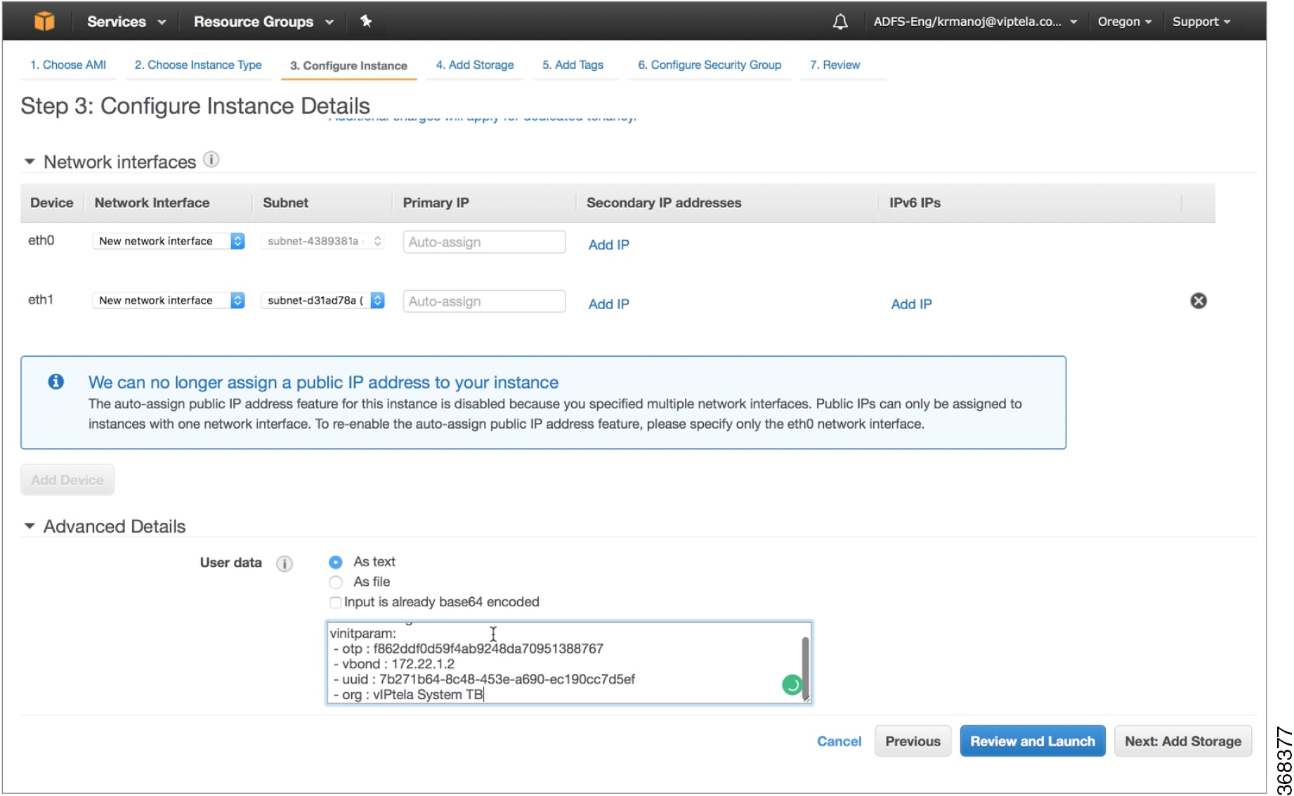
By default, the ge0/0 interface is the router's tunnel interface, and it is configured as a DHCP client. To use a different interface or to use a static IP address, and if you did not attach a device configuration template to the router, change the vEdge Cloud router's configuration from the CLI. See Configuring Network Interfaces.
Install the Certificate on the vEdge Cloud Router
If you are using automated vEdge Cloud certificate authorization, which is the default, after you configure the vEdge Cloud router instance, vManage NMS automatically installs a certificate on the router and the router's token changes to its serial number. You can display the router's serial number in the Configuration ► Devices screen. After the router's control connections to the vManage NMS come up, any templates attached to the router are automatically pushed to the router.
If you are using manual vEdge Cloud certificate authorization, after you configure the vEdge Cloud router instance, follow this procedure to install a certificate on the router:
-
Install the enterprise root certificate chain on the router:
vEdge# request root-cert-chain install filename [vpn vpn-id]Then, the vManage NMS generates a CSR.
-
Download the CSR:
-
in vManage NMS, select the Configuration ► Certificates screen.
-
Select the vEdge Cloud router for which to sign a certificate.
-
Click the More Actions icon to the right of the row and select View CSR.
-
To download the CSR, click Download.
-
-
Send the certificate to a third-party signing authority, to have them sign it.
-
Import the certificate into the device:
-
In the Configuration ► Certificates screen, click the Controllers tab.
-
Click the Install Certificate button located in the upper-right corner of the screen.
-
In the Install Certificate screen, paste the certificate into the Certificate Text field, or click Select a File to upload the certificate in a file.
-
Click Install.
-
-
Issue the following REST API call, specifying the IP address of your vManage NMS:
https://vmanage-ip-address/dataservice/system/device/sync/rootcertchain
Create the vEdge Cloud Router Bootstrap Configuration from the CLI
It is recommended that you generate the vEdge Cloud router's bootstrap configuration using the vManage NMS If, for some reason, you do not want to do this, you can create the bootstrap configuration using the CLI. With this process, you must still, however, use the vManage NMS. You collect some of this information for the bootstrap configuration from the vManage NMS, and after you have created the bootstrap configuration, you use the vManage NMS to install the signed certificate on the router.
Installing signed certificates by creating a bootstrap configuration from the CLI is a three-step process:
-
Edit the router's configuration file to add the DNS name or IP address of the vBond orchestrator and your organization name.
-
Send the router's chassis and token numbers to the vManage NMS.
-
Have the vManage NMS authenticate the vEdge Cloud router and install the signed certificate on the router.
To edit the vEdge Cloud router's configuration file from the CLI:
-
Open a CLI session to the vEdge Cloud router via SSH. To do this in vManage NMS, select the Tools ► SSH Terminal screen, and select the desired router.
-
Log in as the user admin, using the default password, admin. The CLI prompt is displayed.
-
Enter configuration mode:
vEdge# config vEdge(config)# -
Configure the IP address of the vBond orchestrator or a DNS name that points to the vBond orchestrator. The vBond orchestrator's IP address must be a public IP address:
vEdge(config)# system vbond (dns-name | ip-address) -
Configure the organization name:
vEdge(config-system)# organization-name name -
Commit the configuration:
vEdge(config)# commit and-quit
vEdge#
To send the vEdge Cloud router's chassis and token numbers to the vManage NMS:
-
Locate the vEdge Cloud router's token and chassis number:
-
In vManage NMS, select the Configuration ► Devices screen.
-
In the vEdge List tab, locate the vEdge Cloud router.
-
Make a note of the values in the vEdge Cloud router's Serial No./Token and Chassis Number columns.
-
-
Send the router's bootstrap configuration information to the vManage NMS:
vEdge# request vedge-cloud activate chassis-number chassis-number token token-number
Issue the show control local-properties command on the router to verify the vBond IP address, the organization name the chassis number, and the token. You can also verify whether the certificate is valid.
Finally, have the vManage NMS authenticate the vEdge Cloud router and install the signed certificate on the router.
If you are using automated vEdge Cloud certificate authorization, which is the default, the vManage NMS uses the chassis and token numbers to authenticate the router. Then, the vManage NMS automatically installs a certificate on the router and the router's token changes to a serial number. You can display the router's serial number in the Configuration ► Devices screen. After the router's control connections to the vManage NMS come up, any templates attached to the router are automatically pushed to the router.
If you are using manual vEdge Cloud certificate authorization, after you configure the vEdge Cloud router instance, follow this procedure to install a certificate on the router:
-
Install the enterprise root certificate chain on the router:
vEdge# request root-cert-chain install filename [vpn vpn-id]After you install the root chain certificate on the router, and after the vManage NMS receives the chassis and token numbers, the vManage NMS generates a CSR.
-
Download the CSR:
-
in vManage NMS, select the Configuration ► Certificates screen.
-
Select the vEdge Cloud router for which to sign a certificate.
-
Click the More Actions icon to the right of the row and select View CSR.
-
To download the CSR, click Download.
-
-
Send the certificate to a third-party signing authority, to have them sign it.
-
Import the certificate into the device:
-
In the Configuration ► Certificates screen, click the Controllers tab.
-
Click the Install Certificate button located in the upper-right corner of the screen.
-
In the Install Certificate screen, paste the certificate into the Certificate Text field, or click Select a File to upload the certificate in a file.
-
Click Install.
-
-
Issue the following REST API call, specifying the IP address of your vManage NMS:
https://vmanage-ip-address/dataservice/system/device/sync/rootcertchain
Install Signed Certificates in Releases 16.3 and Earlier
For vEdge Cloud router virtual machine (VM) instances running Releases 16.3 and earlier, when the vEdge Cloud router VM starts, it has a factory-default configuration, but is unable to join the overlay network because no signed certificate is installed. You must install a signed Symantec certificate on the vEdge Cloud router so that it can participate in the overlay network.
To generate a certificate signing request (CSR) and install the signed certificate on the vEdge Cloud router:
-
Log in to the vEdge Cloud router as the user admin, using the default password, admin. If the vEdge Cloud router is provided through AWS, use your AWS key pair to log in. The CLI prompt is displayed.
-
Generate a CSR for the vEdge Cloud router:
vEdge# request csr upload pathpath is the full path and filename where you want to upload the CSR. The path can be in a directory on the local device or on a remote device reachable through FTP, HTTP, SCP, or TFTP. If you are using SCP, you are prompted for the directory name and filename; no file path name is provided. When prompted, enter and then confirm your organization name. For example:
vEdge# request csr upload home/admin/vm9.csr Uploading CSR via VPN 0 Enter organization name : Cisco Re-enter organization name : Cisco Generating CSR for this vEdge device ........[DONE] Copying ... /home/admin/vm9.csr via VPN 0 CSR upload successful -
Log in to the Symantec Certificate Enrollment portal:
https://certmanager.<wbr/>websecurity.symantec.com/<wbr/>mcelp/enroll/index?jur_hash=<wbr/>f422d7ceb508a24e32ea7de4f78d37<wbr/>f8
-
In the Select Certificate Type drop-down, select Standard Intranet SSL and click Go. The Certificate Enrollment screen is displayed. Cisco SD-WAN uses the information you provide on this form to confirm the identity of the certificate requestor and to approve your certificate request. To complete the Certificate Enrollment form:
-
In the Your Contact Information section, specify the First Name, Last Name, and Email Address of the requestor.
-
In the Server Platform and Certificate Signing section, select Apache from the Select Server Platform drop-down. In the Enter Certificate Signing Request (CSR) box, upload the generated CSR file, or copy and paste the contents of the CSR file. (For details about how to do this, log in to support.viptela.com. Click Certificate, and read the Symantec certificate instructions.)
-
In the Certificate Options section, enter the validity period for the certificate.
-
In the Challenge Phrase section, enter and then re-enter a challenge phrase. You use the challenge phrase to renew, and, if necessary, to revoke a certificate on the Symantec Customer Portal. It is recommended that you specify a different challenge phrase for each CSR.
-
Accept the Subscriber Agreement. The system generates a confirmation message and sends an email to the requestor confirming the certificate request. It also sends an email to the Cisco to approve the CSR.
-
-
After Cisco approves the CSR, Symantec sends the signed certificate to the requestor. The signed certificate is also available through the Symantec Enrollment portal.
-
Install the certificate on the vEdge Cloud router:
vEdge# request certificate install filename [vpn vpn-id]The file can be in your home directory on the local device, or it can be on a remote device reachable through FTP, HTTP, SCP, or TFTP. If you are using SCP, you are prompted for the directory name and filename; no file path name is provided.
-
Verify that the certificate is installed and valid:
vEdge# show certificate validity
After you have installed the certificate on the vEdge Cloud router, the vBond orchestator is able to validate and authenticate the router, and the router is able to join the overlay network.
What's Next
See Send vEdge Serial Numbers to the Controller Devices.
Manage Certificates in Cisco vManage
Peform certificate operations in Cisco vManage on the Configuration > Certificates page.
-
Top bar—On the left are the menu icon, for expanding and collapsing the Cisco vManage menu, and the vManage product name. On the right are a number of icons and the user profile drop-down.
-
Title bar—Includes the title of the screen, Certificates.
-
WAN Edge List tab—Install the router authorized serial number file on the controllers in the overlay network and manage the serial numbers in the file. When you first open the Certificates screen, the WAN Edge List tab is selected.
-
Send to Controllers—Send the WAN edge router chassis and serial numbers to the controllers in the network.
-
Table of WAN edge routers in the overlay network—To re-arrange the columns, drag the column title to the desired position.
-
-
Controllers tab—Install certificates and download the device serial numbers to the vBond orchestrator.
-
Send to vBond—Send the controller serial numbers to the Cisco vBond Orchestrator.
-
Install Certificate—Install the signed certificates on the controller devices. This button is available only if you select Manual in .
-
Export Root Certificate—Display a copy of the root certificate for the controller devices that you can download to a file.
-
Table of controller devices in the overlay network—To re-arrange the columns, drag the column title to the desired position.
-
Certificate status bar—Located at the bottom of the screen, this bar is available only if you select Server Automated in . It displays the states of the certificate installation process:
-
Device Added
-
Generate CSR
-
Waiting for Certificate
-
Send to Controllers
-
-
-
Search box—Includes the Search Options drop-down, for a Contains or Match string.
-
Refresh icon—Click to refresh data in the device table with the most current data.
-
Export icon—Click to download all data to a file, in CSV format.
-
Show Table Fields icon—Click the icon to display or hide columns from the device table. By default, all columns are displayed.
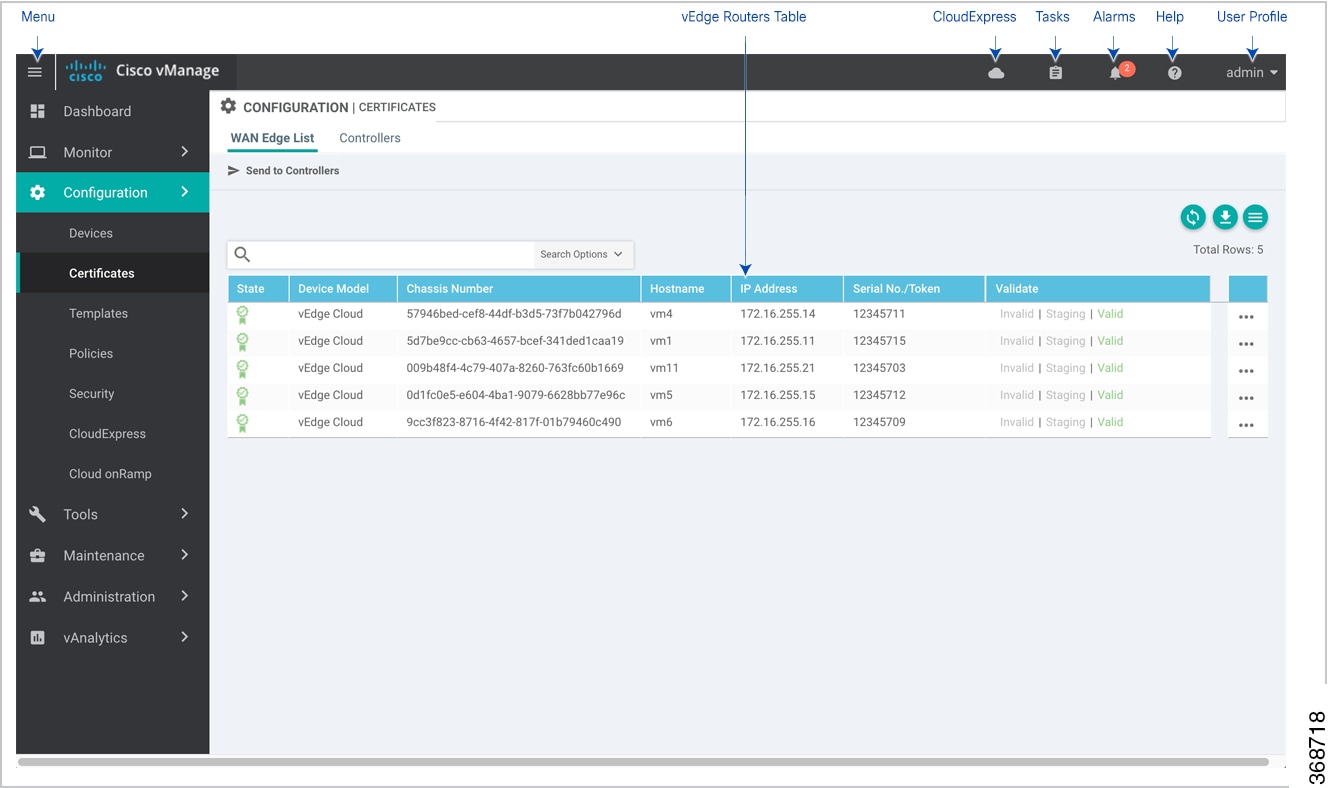
Check the WAN Edge Router Certificate Status
In the WAN Edge List tab, check the Validate column. The status can be one of the following:
-
Valid (shown in green)—The router's certificate is valid.
-
Staging (shown in yellow)—The router is in the staging state.
-
Invalid (shown in red)—The router's certificate is not valid.
Validate a WAN Edge Router
When you add Cisco vEdge devices and WAN routers to the network using the screen, you can automatically validate the routers and send their chassis and serial numbers to the controller devices by clicking the checkbox Validate the uploaded WAN Edge List and send to controllers. If you do not select this option, you must individually validate each router and send their chassis and serial numbers to the controller devices. To do so:
-
In the WAN Edge List tab, select the router to validate.
-
In the Validate column, click Valid.
-
Click OK to confirm the move to the valid state.
-
Repeat the steps above for each router you wish to validate.
-
Click the Send to Controllers button in the upper left corner of the screen to send the chassis and serial numbers of the validated routers to the controller devices in the network. Cisco vManage NMS displays the Push WAN Edge List screen showing the status of the push operation.
Stage a WAN Edge Router
When you initially bring up and configure a WAN Edge router, you can place it in staging state using the Cisco vManage NMS. When the router is in this state, you can configure the router, and you can test that the router is able to establish operational connections with the vSmart controller and the vManage NMS.
After you physically place the router at its production site, you change the router's state from staging to valid. It is only at this point that the router joins the actual production network. To stage a router:
-
In the WAN Edge List tab, select the router to stage.
-
In the Validate column, click Staging.
-
Click OK to confirm the move to the staging state.
-
Click Send to Controllers in the upper left corner of the screen to sync the WAN edge authorized serial number file with the controllers. vManage NMS displays the Push WAN Edge List screen showing the status of the push operation.
-
To unstage, validate the WAN Edge Router.
Invalidate a WAN Edge Router
-
In the WAN Edge List tab, select the router to invalidate.
-
In the Validate column, click Invalid.
-
Click OK to confirm the move to the invalid state.
-
Repeat the steps above for each router you wish to invalidate.
-
Click the Send to Controllers button in the upper left corner of the screen to send the chassis and serial numbers of the validated routers to the controller devices in the network. Cisco vManage NMS displays the Push WAN Edge List screen showing the status of the push operation.
Send the Controller Serial Numbers to Cisco vBond Orchestrator
To determine which controllers in the overlay network are valid, the Cisco vBond Orchestrator keeps a list of the controller serial numbers. The Cisco vManage NMS learns these serial numbers during the certificate-generation process.
To send the controller serial numbers to the Cisco vBond Orchestrator:
-
In the Controllers tab, check the certificate status bar at the bottom of the screen. If the Send to Controllers check mark is green, all serial numbers have already been sent to the Cisco vBond Orchestrator. If it is grey, you can send one or more serial numbers to the Cisco vBond Orchestrator.
-
Click the Send to vBond button in the Controllers tab. A controller's serial number is sent only once to the Cisco vBond Orchestrator. If all serial numbers have been sent, when you click Send to vBond, an error message is displayed. To resend a controller's serial number, you must first select the device and then select Invalid in the Validity column.
After the serial numbers have been sent, click the Tasks icon in the Cisco vManage toolbar to display a log of the file download and other recent activities.
Install Signed Certificate
If in , you selected the Manual option for the certificate-generation process, use the Install Certificate button to manually install certificates on the controller devices.
After Symantec or your enterprise root CA has signed the certificates, they return the files containing the individual signed certificates. Place them on a server in your local network. Then install them on each controller:
-
In the Controllers tab, click Install Certificate.
-
In the Install Certificate window, select a file, or copy and paste the certificate text.
-
Click Install to install the certificate on the device. The certificate contains information that identifies the controller, so you do not need to select the device on which to install the certificate.
-
Repeat Steps the steps above to install additional certificates.
Export Root Certificate
-
In the Controllers tab, click the Export Root Certificate button.
-
In the Export Root Certificate window, click Download to export the root certificate to a file.
-
Click Close.
View a Certificate Signing Request
-
In the WAN Edge List or Controllers tab, select a device.
-
Click the More Actions icon to the right of the row, and click View CSR to view the certificate signing request (CSR).
View a Device Certificate Signing Request
-
In the WAN Edge List or Controllers tab, select a Cisco IOS XE SD-WAN device.
-
Click the More Actions icon to the right of the row, and click View Device CSR to view the certificate signing request (CSR).
For a Cisco IOS XE SD-WAN device where trustpoint has been configured, clicking the More Actions icon allows you to view three options:
-
View Device CSR
-
Generate Feature CSR
-
View Feature CSR
-
View the Certificate
-
In the Controllers tab, select a device.
-
Click the More Actions icon to the right of the row and click View Certificate.
Generate a Certificate Signing Request
-
In the Controllers tab, select a device.
-
Click the More Actions icon to the right of the row and click Generate CSR.
-
In the Generate CSR window, click Download to download the file to your local PC (that is, to the PC you are using to connect to the Cisco vManage NMS).
-
Repeat the steps above for each controller for which you are generating a CSR.
Generate a Feature Certificate Signing Request
-
In the WAN Edge List tab, choose a Cisco IOS XE SD-WAN device.
-
Click the More Actions icon to the right of the row and click Generate Feature CSR.
-
In the Generate Feature CSR window, click OK to continue with the generation of feature CSR. This step authenticates the device trustpoint that has been set and extracts the CSR from the device.
-
Repeat the steps above for each device for which you are generating a CSR.
Reset the RSA Key Pair
-
In the Controllers tab, select a device.
-
Click the More Actions icon to the right of the row and click Reset RSA.
-
Click OK to confirm resetting of the device's RSA key and to generate a new CSR with new public or private keys.
Invalidate a Device
-
In the Controllers tab, select a device.
-
Click the More Actions icon to the right of the row and click Invalidate.
-
Click OK to confirm invalidation of the device.
View Log of Certificate Activities
To view the status of certificate-related activities:
-
Click the Tasks icon located in the vManage toolbar. Cisco vManage NMS displays a list of all running tasks along with the total number of successes and failures.
-
Click a row to see details of a task. Cisco vManage NMS opens a status window displaying the status of the task and details of the device on which the task was performed.
View a Signed Certificate
Signed certificates are used to authenticate Cisco SD-WAN devices in the overlay network. To view the contents of a signed certificate using Cisco vManage:
-
In Cisco vManage, select the Configuration ► Certificates screen.
-
From the Certificates title bar, select Controllers.
-
Select the device whose certificate you wish to view.
-
Click the More Actions icon to the right of the row, and select View Certificate to view the installed certificate.
Manage Device Templates
Edit a Device Template
-
In the Device or Feature tab, select a template.
-
Click the More Actions icon to the right of the row and click Edit.
You cannot change the name of a device or feature template when that template is attached to a device.
Note that you can edit templates simultaneously from one or more vManage servers. For simultaneous template edit operations, the following rules apply:
-
You cannot edit the same device or feature template simultaneously.
-
When you are editing a device template, all other feature templates attached to that device template are locked and you cannot perform any edit operations on them.
-
When you are editing a feature template that is attached to a device template, that device template as well as all other feature templates attached to it are locked and you cannot perform any edit operations on them.
Delete a Template
Deleting a template does not remove the associated configuration from devices.
-
In the Device or Feature tab, select a template.
-
Click the More Actions icon to the right of the row and click Delete.
-
Click OK to confirm deletion of the template.
Copy a Template
-
In the Device or Feature tab, select a template.
-
Click the More Actions icon to the right of the row and click Copy.
-
Enter a new template name and description.
-
Click Copy.
Edit a CLI Device Template
-
In the Device tab, select a template.
-
Click the More Actions icon to the right of the row and click Edit.
-
In the Device CLI Template window, edit the template.
-
Click Update.
Manage Users Using Cisco vManage
Use the Manage Users screen to add, edit, view, or delete users and user groups from Cisco vManage.
Only a user logged in as the admin user or a user who has Manage Users write permission can add, edit, or delete users and user groups from Cisco vManage.
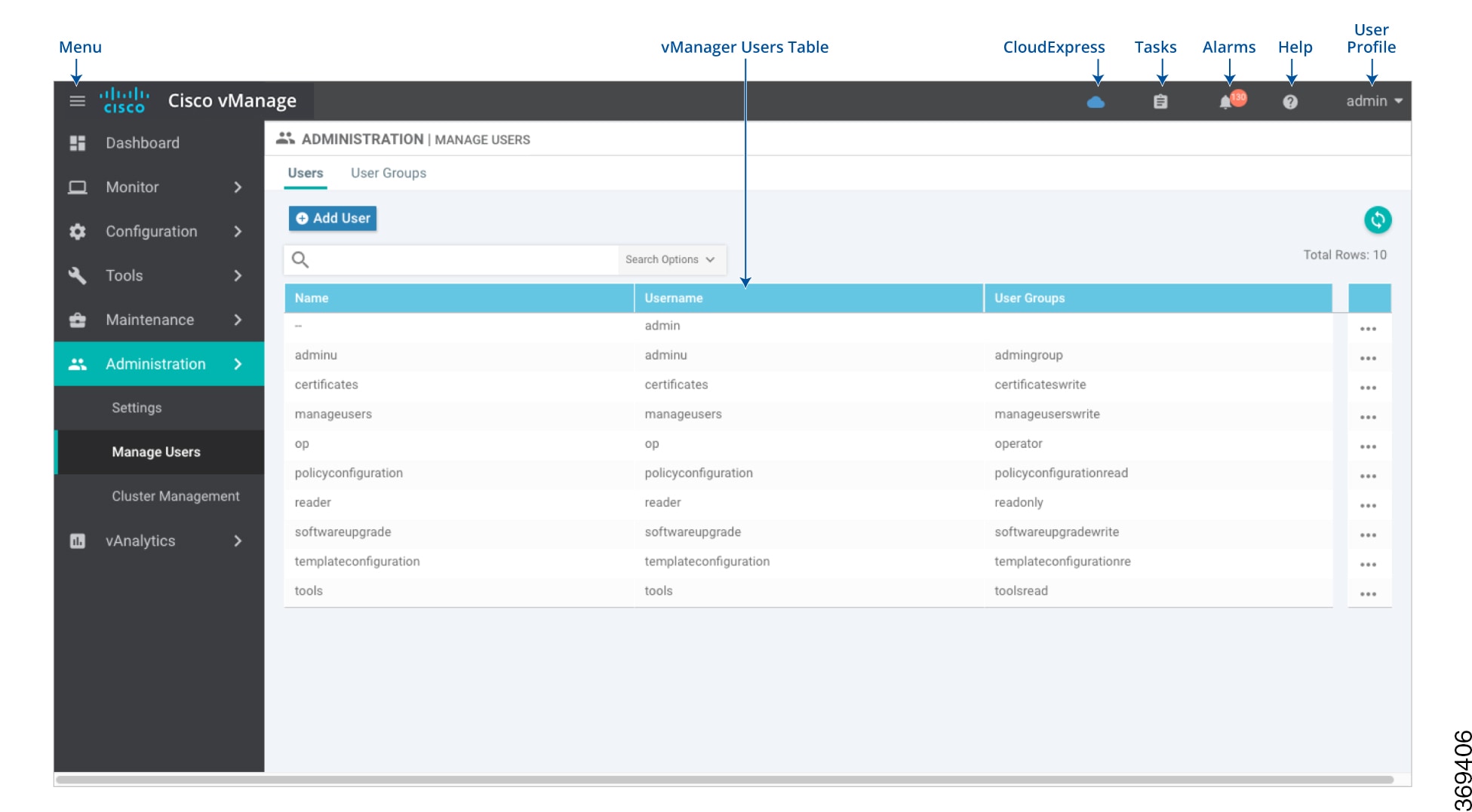
Each user group can have read or write permission for the features listed in this section. Write permission includes read permission.
Note |
All user groups, regardless of the read or write permissions selected, can view the information displayed in the Cisco vManage Dashboard screen. |
|
Feature |
Read Permission |
Write Permission |
|---|---|---|
|
Alarms |
Set alarm filters and view alarms generated on the devices on the screen. |
No additional permissions. |
|
Audit Log |
Set audit log filters and view a log of all activities on the devices on the screen and the screen. |
No additional permissions. |
|
Certificates |
View a list of the devices in the overlay network under . View a CSR and certificate on the screen. |
Validate and invalidate a device, stage a device, and send the serial number of valid controller devices to the Cisco vBond Orchestrator on the screen. Generate a CSR, install a signed certificate, reset the RSA key pair, and invalidate a controller device on the screen. |
|
Cluster |
View information about services running on Cisco vManage, a list of devices connected to a Cisco vManage server, and the services that are available and running on all the Cisco vManage servers in the cluster on the screen. |
Change the IP address of the current Cisco vManage, add a Cisco vManage server to the cluster, configure the statistics database, edit and remove a Cisco vManage server from the cluster on the screen. |
|
Device Inventory |
View the running and local configuration of devices, a log of template activities, and the status of attaching configuration templates to devices on the screen. View the running and local configuration of the device and the status of attaching configuration templates to controller devices on the screen. |
Upload the device's authorized serial number file to Cisco vManage, toggle a device from Cisco vManage configuration mode to CLI mode, copy a device configuration, and delete the device from the network on the screen. Add and delete controller devices from the overlay network, and edit the IP address and login credentials of a controller device on the screen. |
|
Device Monitoring |
View the geographic location of the devices on the screen. View events that have occurred on the devices on the screen. View a list of devices in the network, device status summary, DPI and cflowd flow information, TLOC loss, latency, and jitter information, control and tunnel connections, system status, and events on the screen (only when a device is selected). |
Ping a device, run a traceroute, and analyze the traffic path for an IP packet on the screen (only when a device is selected). |
|
Device Reboot |
View a list of devices on which the reboot operation can be performed on the screen. |
Reboot one or more devices on the screen. |
|
Interface |
View information about interfaces on a device on the screen. |
Edit Chart Options to select the type of data to display, and edit the time period for which to display data on the screen. |
|
Manage Users |
View users and user groups on the screen. |
Add, edit, and delete users and user groups from Cisco vManage, and edit user group privileges on the screen. |
|
Policy |
View common policies for all Cisco vSmart Controllers or devices in the network on the screen. |
Create, edit, and delete common policies for all Cisco vSmart Controllers or devices in the network on the screen. |
|
Policy Configuration |
View list of policies created and details about them on the screen. |
Create, edit, and delete common policies for all Cisco vSmart Controllers and devices in the network on the screen. |
|
Policy Deploy |
View the current status of the Cisco vSmart Controllers to which a policy is being applied on the screen. |
Activate and deactivate common policies for all Cisco vManage servers in the network on the screen. |
|
Routing |
View real-time routing information for a device on the screen. |
Add command filters to speed up the display of information on the screen. |
|
Settings |
View the organization name, Cisco vBond Orchestrator DNS/IP address, certificate authorization settings, software version enforced on a device, custom banner on the Cisco vManage login screen, and the current settings for collecting statistics on the screen. |
Edit the organization name, Cisco vBond Orchestrator DNS/IP address, certificate authorization settings, software version enforced on a device, custom banner on the Cisco vManage login screen, current settings for collecting statistics, generate a Certificate Signing Request (CSR) for a web server certificate, and install a certificate on the screen. |
|
Software Upgrade |
View a list of devices, custom banner on Cisco vManage on which a software upgrade can be performed and the current software version running on a device on the screen. |
Upload new software images on devices, upgrade, activate, and delete a software image on a device, and set a software image to be the default image on devices on the screen. |
|
System |
View system-wide parameters configured using Cisco vManage templates on the screen. |
Configure system-wide parameters using Cisco vManage templates on the screen. |
|
Template Configuration |
View feature and device templates on the screen. |
Create, edit, delete, and copy a feature or device template on the screen. |
|
Template Deploy |
View devices attached to a device template on the screen. |
Attach a device to a device template on the screen. |
|
Tools |
Use the Admin Tech command to collect system status information for a device on the screen. |
Use the Admin Tech command to collect system status information for a device, and use the Interface Reset command to shut down and then restart an interface on a device in a single operation on the screen. Rediscover the network to locate new devices and synchronize them with Cisco vManage on the screen. Establish an SSH session to the devices and issue CLI commands on the screen. |
Following is the list of user group permissions for RBAC in a multi-tenant environment:
R stands for Read permission.
W stands for Write permission.
|
Feature |
Provider Admin |
Provider Operator |
Tenant Admin |
Tenant Operator |
|---|---|---|---|---|
|
Cloud OnRamp |
RW |
R |
RW |
R |
|
Colocation |
RW |
R |
RW |
R |
|
RBAC VPN |
RW |
R |
RW |
R |
|
Security |
RW |
R |
RW |
R |
|
Security Policy Configuration |
RW |
R |
RW |
R |
|
vAnalytics |
RW |
R |
RW |
R |
View User Accounts and Add a User
To perform operations on a device, you configure usernames and passwords for users who are allowed to access the device. The Cisco SD-WAN software provides one standard username, admin, and you can create custom usernames, as needed. We recommend that you configure strong passwords for users.
To check Cisco vManage user accounts and the permissions:
-
In Cisco vManage, navigate to .
-
On the Users tab, view all users who have Cisco vManage accounts.
-
In the left pane, click the username. The right pane then shows the features for which the user has read or write permission.
To add a user:
-
On the Users tab, click Add User.
-
In the Add User pop-up window, enter the full name, username, and password for the user. Note that uppercase characters are not allowed in usernames.
-
From the User Groups drop-down list, choose the groups that the user is a member of.
To edit user account information, click the More Actions option to the right of a table row.
-
Click Add. The user is then listed in the user table.
Delete a User
If a user no longer needs access to devices, you can delete the user. When you delete a user, that user no longer has access to the device. Deleting a user does not force log out the user if the user is logged in.
To delete a user:
-
On the Users tab, select the user you wish to delete.
-
Click the More Actions options to the right of the column and click Delete.
-
Click OK to confirm deletion of the user.
Edit User Details
Editing user details lets you update login information for a user, and add or remove a user from a user group. If you edit details for a user who is logged in, the changes take effect after the user logs out.
To edit user details:
-
On the Users tab, select the user whose details you wish to edit.
-
Click the More Actions option to the right of the column and click Edit.
-
Edit login details, and add or remove the user from user groups.
-
Click Update.
Change User Password
You can update passwords for users as needed. We recommend that you use strong passwords.
To change a password for a user:
-
On the Users tab, choose the user whose password you wish to change.
-
Click the More Actions option to the right of the column and click Change Password.
-
Enter password, and then confirm the new password. Note that the user, if logged in, is logged out.
-
Click Done.
Check Users Logged in to a Device Using SSH Sessions
-
In Cisco vManage, navigate to .
-
Select the device you want to use under Hostname.
-
In the right pane, click Real Time.
-
In , under Device Options, chose AAA users for Cisco IOS XE SD-WAN devices.
You see a list of users logged in to this device.
Check Users Logged in to a Device Using HTTP Sessions
-
In Cisco vManage, navigate to .
-
Click User Sessions.
This gives you the list of all active HTTP sessions within Cisco vManage. You see information such as, username, domain, source IP address, and so on.
Manage a User Group
Users are placed in groups, which define the specific configuration and operational commands that the users are authorized to view and modify. A single user can be in one or more groups. The Cisco SD-WAN software provides three standard user groups, and you can create custom user groups, as needed:
-
basic—Includes users who have permission to view interface and system information.
-
netadmin—Includes the admin user, by default, who can perform all operations on the vManage NMS. You can add other users to this group.
-
operator—Includes users who have permission only to view information.
To add a user group:
-
In Cisco vManage, navigate to
. -
On the User Groups tab, click Add User Group.
-
In the Add User Group pop-up window, enter the user group name and select the desired read and write permissions for each feature. Note that uppercase characters are not allowed in user group names.
-
Click OK. The user group is then listed in the left pane.
Each user group can have read or write permission for the features listed below. Write permission includes read permission.
Note: All user groups, regardless of the read or write permissions selected, can view the information displayed on the Cisco vManage Dashboard screen.
Delete a User Group
You can delete a user group when it is no longer needed. For example, you might delete a user group that you created for a specific project when that project ends.
-
In Cisco vManage, navigate to
. -
On the User Groups tab, click the name of the user group you wish to delete. Note that you cannot delete any of the three standard user groups—basic, netadmin, and operator.
-
Click the Trash icon.
-
Click OK to confirm deletion of the user group.
Edit User Group Privileges
You can edit group privileges for an existing user group. This procedure lets you change configured feature read and write permissions for the user group needed.
-
In Cisco vManage, navigate to
. -
On the User Groups tab, select the name of the user group whose privileges you wish to edit. Note that you cannot edit privileges for the three standard user groups—basic, netadmin, and operator.
-
Click the Edit button located directly above the privilege level table, and edit privileges as needed.
-
Click Save.
If an admin user changes the privileges of a user by changing their group, and if that user is currently logged in to the device, the user is logged out and must log back in again.
Preview Device Configuration and View Configuration Differences
For a configuration that you have created from the CLI:
-
In the Device tab, select a device template.
-
Click the More Actions icon to the right of the row and click Change Device Values. The right pane displays the device's configuration, and the Config Preview tab in the upper right corner is selected.
-
In the left pane, click the name of a device.
-
Click the Config Diff tab to view the differences between this configuration and the configuration currently running on the device, if applicable. Click the Back button to edit the variable values entered in the previous screen.
-
Click Configure Devices to push the configuration to the devices. The Status column displays whether the configuration was successfully pushed. Click the right angle bracket to the left of the row to display details of the push operation.
Reset Interfaces
Use the Interface Reset command to shutdown and then restart an interface on a device in a single operation without having to modify the device's configuration.
-
In Cisco vManage, navigate to .
-
From the device table, select the device.
-
Next, go to .
-
In the Interface Reset window, select the desired interface.
-
Click Reset.
Reset a Locked User
If a user is locked out after too many password attempts, an administrator with the required rights can update passwords for this user.
There are two ways to unlock a user account, by changing the password or by getting the user account unlocked.
Note |
Only a netadmin user or a user group with the User Management Write role can perform this operation. |
To reset a user that has been locked out:
-
In the Users tab, choose the user whose account you want to unlock.
-
Click the More Actions option to the right of the column and click Reset Locked User.
-
Click OK to confirm that you want to reset the account. This operation cannot be undone.
Alternatively, you can click Cancel to terminate the operation.
Service Side NAT Workflow
|
Feature Name |
Release Information |
Description |
|---|---|---|
|
Service Side NAT on Cisco IOS XE SD-WAN devices |
Cisco IOS XE Release 17.3.1a Cisco vManage Release 20.3.1 |
To configure service-side NAT using Cisco vManage, configure a centralized data policy using the , and configure a dynamic NAT Pool and Static NAT address using the Service VPN template. |
Recommended Workflow for Service-Side NAT
-
Configure a centralized data policy for the Cisco vSmart controller to include a NAT pool number and action. The direction of the centralized data policy for NAT inside must be from-service. The direction of policy for NAT outside must be from-tunnel.
-
Configure a dynamic NAT Pool number on the service VPN using the NAT configurations under the Service VPN template.
-
Configure Dynamic NAT mapping in Service VPN template.
-
(Optional) Configure Static NAT mapping in service VPN template.
-
For NAT inside the NAT pool subnet and static NAT translation IP addresses are automatically advertised into OMP. For NAT outside, you can manually configure redistribution of the NAT pool subnet and static NAT translation IP addresses to the service-side protocols.
Note
If data policy action is configured for VPN 0, the action is configured for DIA traffic. If the data policy action is configured for any of the service VPNs (example: VPN1) which includes a NAT pool configuration, the action is for service-side NAT.
Create and Apply a Centralized Data Policy for NAT
Centralized data policy is policy that is configured on a Cisco vSmart Controller and that affects data traffic being transmitted between the routers on the Cisco SD-WAN overlay network.
-
In the Cisco vManage, select the screen.
-
Select the Centralized Policy tab.
-
Click Add Policy. The policy configuration wizard opens. For additional information, refer to Create Centralized Data Policy.
-
Create policy lists. See Policy Lists.
-
Configure traffic rules. See Traffic Rules.
-
Apply policies to VPNs. See Apply Policies. Select the direction for applying the policy as All, From Tunnel or From Service.
Table 69. Dynamic and Static NAT Application NAT Configuration Data-Policy Direction Dynamic NAT Inside only (NAT Pool) From-service Dynamic NAT Outside only (NAT Pool) From-tunnel Dynamic NAT Inside (NAT Pool) + Static NAT Inside only From-service Dynamic NAT Inside (NAT Pool) + Static Port Forwarding only From-service Dynamic NAT Outside (NAT Pool) + Static NAT Outside only From-tunnel Two or more of above combinations all -
Activate the policy. See Activate a Centralized Data Policy
Configure Dynamic and Static NAT
Sample Topology
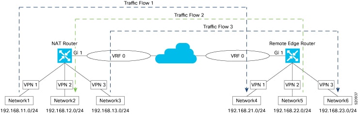
Configure NAT
-
In Cisco vManage, choose .
-
In the Feature tab, click Add Template.
-
Choose the device
-
Select the device and click Cisco VPN template.
-
From the Device Model drop-down list, select the type of device for which you are creating the template.
-
In the Template Name field, enter a name for the template. The name can be up to 128 characters and can contain only alphanumeric characters.
-
In the Template Description field, enter a description of the template. The description can be up to 2048 characters and can contain only alphanumeric characters.
-
In the Basic Configuration tab, enter a service VPN number (VPNs 1 through 511, and 513 through 65527) in the VPN field.
Configure Dynamic NAT
-
To configure dynamic NAT, click the NAT tab. Under NAT Pool, click New NAT Pool. Enter the required parameters and click Add.
|
Parameter Name |
Description |
|---|---|
|
NAT Pool Name |
Enter a NAT pool number configured in the centralized data policy. NAT pool name must be unique across VPNs and VRFs. You can configure up to 31 (1–32) NAT pools per router. |
| NAT Pool Range Start |
Enter a starting IP address for the NAT pool.
|
| NAT Pool Range End |
Enter a closing IP address for the NAT pool.
|
|
NAT Pool Prefix Length |
Enter the NAT pool prefix length. |
|
Overload |
Click On to enable per-port translation. Default is On. If Overload is set to Off only the Dynamic NAT is configured on the end device. Per port NAT is not configured. |
|
NAT direction |
Choose direction of NAT. |
Configure Static NAT
To configure static NAT, click the NAT tab. Under Static NAT, click New Static NAT . Enter the required parameters and click Add.
|
Parameter Name |
Description |
|---|---|
|
Mark as Optional Row |
Check Mark as Optional Row to mark this configuration as device-specific. To include this configuration for a device, enter the requested variable values when you attach a device template to a device, or create a template variables spreadsheet to apply the variables. |
|
Source IP |
Enter the inside local address as source IP address. |
|
Translated Source IP Address |
Enter the inside global address as the translated source IP address. Maps a public IP address to a private source address. |
|
Static NAT Direction |
Select the direction in which to perform network address translation. |
|
Inside |
Select Inside to translate the IP address of packets that are coming from the service side of the device and are destined for the transport side of the router. |
|
Outside |
Select Outside to translate the IP address of packets that are coming to the device from the transport side device and are destined for a service-side device. |
Note |
Static NAT IP addresses must not overlap with NAT Pool IP addresses. |
Configure Port Forwarding
-
To create a port forwarding rule, click and configure the following parameters. You can define up to 128 port-forwarding rules to allow requests from an external network to reach devices on the internal network.
|
Parameter Name |
Description |
|---|---|
|
Source Port |
Enter a port number to define the source port to be translated.Range: 0 through 65535 |
|
Source IP Address |
Enter the Source IP address to be translated. |
|
Translate Port |
Enter the port number to apply port forwarding to. Range: 0 through 65535 |
|
Protocol |
Select TCP or UDP protocol to which to apply the port-forwarding rule. To match the same ports for both TCP and UDP traffic, configure two rules. |
|
Translated Source IP address |
Specify the NAT IP address that will be advertised into OMP. Port forwarding is applied to traffic that destined to this IP address from overlay with translated port match. |
To save the template, click Save.
Verify Service-Side NAT
-
In Cisco vManage, select the screen.
-
Locate the router with the transport interface, using the Sort options drop-down and the Search box, or scroll through the list of devices in the device table.
-
Select the router by clicking the hostname.
-
Select Real Time from the left pane.
-
Select Endpointpoint Tracker Info from the Device Options drop-down.
Steps to Bringup Overlay Network
Bringing Up the Overlay Network
The following table lists the tasks for bringing up the overlay network using the Cisco vManage.
|
Bringup Task |
Step-by-Step Procedure |
|---|---|
|
Step 1: Start the vManage NMS. |
|
|
Step 2: Start the vBond orchestrator. |
|
|
Step 3: Start the vSmart controller. |
|
|
Step 4: Configure the router. |
|
|
Step 5: Connect AC power and boot a hardware router. |
|
Summary of the User Portion of the Bringup Sequence
In a general sense, what you do to bring up the Cisco SD-WAN overlay network is what you would do to bring up any network: you plan out the network, create device configurations, and then deploy the network hardware and software components. These components include all the Cisco vEdge devices, all the traditional routers that participate in the overlay network, and all the network devices that provide shared services across the overlay network, such as firewalls, load balancers, and IDP systems.
The table below summarizes the steps for the user portion of the Cisco SD-WAN overlay network bringup. The details of each step are provided in the articles listed in the Procedure column. While you can bring up the Cisco vEdge devices in any order, it is recommended that you deploy them in the order listed below, which is the functional order in which the devices verify and authenticate themselves.
If your network has firewall devices, see Firewall Ports for Cisco SD-WAN Deployments.
|
Workflow |
Procedure |
|
|---|---|---|
|
1 |
|
Plan out your overlay network. See Components of the Cisco SD-WAN Solution. |
|
2 |
|
On paper, create device configurations that implement the desired architecture and functionality. See the Software documentation for your software release. |
|
3 |
|
Download the software images. |
|
4 |
|
Deploy Cisco vManage in the data center:
|
|
5 |
|
Deploy the Cisco vBond Orchestrator:
|
|
6 |
|
Deploy the Cisco vSmart Controller in the data center:
|
|
7 |
|
Deploy the Cisco vEdge routers in the overlay network:
|
Use Variable Values in Configuration Templates
An overlay network might have multiple devices of the same type that have nearly identical configurations. This situation most commonly occurs with routers when the routers that are located in multiple stores or branch locations provide identical services, but each individual router has its own hostname, IP address, GPS location, and other site-specific properties, such as BGP neighbors. This situation also occurs in a network with redundant controller devices, such as Cisco vSmart Controllers, which must all be configured with identical policies, and Cisco vManage systems. Again, each controller has its own individual parameters, such as hostname and IP address.
To simplify the configuration process for these devices, you can create a single configuration template that contains both static configuration values and variable values. The static values are common across all the devices, and the variable values apply only to an individual device. You provide the actual values for the variables when you attach the individual device to the device configuration template.
You can configure a variable value for a parameter in a feature configuration template in two ways:
-
Select the parameter scope to be Device Specific—For an individual configuration parameter, select Device Specific to mark the parameter as a variable. Each variable must be identified by a unique text string, which is called a key. When you select Device Specific, an Enter Key box opens and displays the default key. You can use the default key, or you can change it by typing a new string and then moving the cursor out of the Enter Key box.
-
Mark a group of related parameters as optional—For some features in some feature configuration templates, you can mark the entire feature as optional. To mark the feature in this way, click Mark as Optional Row in a section of a feature configuration template. The variable parameters are then dimmed, and you cannot configure values for them in the feature configuration template.
You enter the device-specific values for the variables when you attach the device to the configuration, in one of the following ways:
-
From a file—When you are attaching a template to a device, you load a file to the vManage NMS. This is an Excel file in CSV format that lists all the variables and defines the variable's value for each device.
-
Manually—When you attach a device template to a device, the Cisco vManage prompts you for the values for each of device-specific parameters, and you type in the value for each parameter.
Use a File for Variable Parameters
To load device-specific variable values from a file, you create a template variables file. This file is an Excel file in CSV format that lists all the variables in your the configurations of your devices and defines the values for each variable. You create this file offline and then import it into Cisco vManage server when you attach a device configuration to one or more devices in the overlay network.
We recommend that you create a template variables CSV file when your overlay network has more than a small number of Cisco IOS XE SD-WAN devices.
CSV File Format
The CSV file is an Excel spreadsheet that contains one column for each variable that is required for the configuration of a device. The header row contains the variable names (one variable per column), and each row after that corresponds to a device and defines the values of the variables for that device.
You can create a single spreadsheet for all devices in the overlay network—Cisco IOS XE SD-WAN devices, Cisco vManage systems, Cisco vSmart Controllers, and Cisco vBond Orchestrators—or you can create one spreadsheet for each device type. The system determines the device type from its serial number.
In the spreadsheet, for each device type and for each individual device, you specify values only for the required variables. When you do not need to specify a value for a variable, simply leave that cell blank.
The first three columns in the spreadsheet must be the following items and must be in the order shown:
|
Column |
Column Heading |
Description |
|---|---|---|
|
1 |
csv-deviceId |
Serial number of the device (used to uniquely identify the device). For Cisco IOS XE SD-WAN devices, you receive the serial numbers in the authorized serial number file sent to you from Cisco. For other devices, the serial number is included in the signed certificate you receive from Symantec or from your root CA. |
|
2 |
csv-deviceIP |
System IP address of the device (used to populate the system ip address command). |
|
3 |
csv-host-name |
Hostname of the device (used to populate the system hostname command). |
The headings for the remaining columns must be unique variable keys that are defined in the Enter Key box of a feature configuration template. These remaining columns can be in any order.
Generate a Skeleton CSV File
You can create a template variables CSV file manually, with the format described in the previous section, or you can haveCisco vManage generate a skeleton CSV file that contains all the required columns and column headings. This generated CSV file has one row for each Cisco device type, and it has the column headings for each of the variables that are required by all the feature templates included in the device configuration. The column heading text corresponds to the key string that identifies a device-specific parameter. Then you populate the rows with values for each variable.
To have Cisco vManage generate a skeleton CSV file:
-
In Cisco vManage, select .
-
From the Templates title bar, select Feature.
-
Click Add Template.
-
Create the required feature templates for one Cisco IOS XE SD-WAN device router, one Cisco vSmart Controller, one Cisco vManage system, and one Cisco vBond Orchestrator.
In each feature template:
-
For fields that have default values, verify that you want to use that value for all devices. If you do not want to use the default, change the scope to Global or Device specific.
-
For fields that apply to all devices, select the Global icon next to the field and set the desired global values.
-
For fields that are device specific, select the Device-specific icon next to the field and leave the field blank.
-
-
For each Cisco device type, create a device template.
-
In the screen, click the Device tab.
-
In the Template List table, select the desired device template.
-
Click the More Actions icon to the right of the row and click Export CSV.
-
Repeat Steps 7 and 8 for each device template.
Edit the exported CSV file, adding at a minimum the device serial number, device system IP address, and device hostname for each device in the overlay network. Then add values for desired device-specific variables for each device. Note that variable names cannot contain forward slashes (/) or backwards slashes (\).
If desired, you can combine the CSV files into a single file.
Import a CSV File
To use the device-specific variable values in the CSV file, import the file when you are attaching a device template to the Viptela device:
-
In Cisco vManage, select .
-
From the Templates title bar, select Device.
-
For the desired template, click the More Actions icon to the right of the row, and Select Attach Devices.
-
In the Attach Devices popup, select the desired devices in the Available Devices box and click the arrow to move them to the Selected Devices box.
-
Click Attach.
-
Click the Up arrow on the right side of the screen. The Upload CSV File box displays.
-
Choose the CSV file to upload, and click Upload.
During the attachment process, click Import file to load the Excel file. If Cisco vManage detects duplicate system IP addresses for devices in the overlay network, it displays a warning message or a pop-up window. You must correct the system IP addresses to remove any duplicates before you can continue the process of attaching device templates to Viptela devices.
Manually Enter Values for Device-Specific Variables and for Optional Rows
For parameters in a feature template that you configure as device-specific, when you attach a device template to a device, Cisco vManage prompts you for the values to use for these parameters. Entering device-specific values in this manner is useful in test or POC networks, or if you are deploying a small network. This method generally does not scale well for larger networks.
For situations in which the configuration for many devices is identical except for a few parameters, in the feature configuration template, you can specify that the parameter be an optional row in the configuration. By selecting optional row, the feature template automatically marks the parameters as device-specific, and these parameters are dimmed so that you cannot set them in the template. You do not have to individually mark the parameters as device specific. Then, when you attach a device template to a device, Cisco vManage prompts you for the values to use for these parameters. Using optional rows to enter device-specific values is useful when a group of many Cisco IOS XE SD-WAN devices provide identical services at their branch or site, but individual routers have their own hostname, IP address, GPS location, and other site or store properties, such as BGP neighbors.
Optional rows are available for some parameters in some feature configuration templates. To treat a parameter or set of parameters as an optional row, click the Mark as Optional Row box. For these types of parameters, the feature configuration template has a table listing all the configured parameters. The Optional column indicates which are optional rows,
To manually enter values for device-specific variables or for variables in optional rows when you attach the template to a device:
-
In Cisco vManage, select .
-
From the Templates title bar, click the Device tab.
-
In the Template List, select the desired device template.
-
Click the More Actions icon to the right of the row and click Attach Devices. The Attach Devices dialog box opens.
-
In the Available Devices column on the left, select a group and search for one or more devices, select a device from the list, or click Select All.
-
Click the arrow pointing right to move the device to the Selected Devices column on the right.
-
Click Attach.
-
In the Chassis Number List, select the desired device.
-
Click the More Actions icon to the right of the row and click Edit Device Template. The Update Device Template dialog box opens.
-
Enter values for the optional parameters. When you are using optional rows, if you do not want to include the parameter for the specific device, do not specify a value.
-
Click Update.
-
Click Next.
If any devices have the same system IP address, a pop-up or an error message is displayed when you click Next. Modify the system IP addresses so that there are no duplicates, and click Save. Then click Next again.
-
In the left pane, select the device. The right pane displays the device's configuration and the Config Preview tab in the upper right corner is selected.
Click the Config Diff tab to preview the differences between this configuration and the configuration currently running on the device, if applicable. Click the Back button to edit the variable values entered in the previous screen.
-
Click Configure Devices to push the configuration to the devices.
The Status column displays whether the configuration was successfully pushed. Click the right angle bracket to the left of the row to display details of the push operation.
Upload WAN Edge Router Authorized Serial Number File
|
Feature Name |
Release Information |
Description |
|---|---|---|
|
Remove Certificate SUDI requirement. |
Cisco IOS XE Release 17.3.1a Cisco vManage Release 20.3.1 |
This feature allows you to use a subject SUDI serial number instead of a certificate serial number to add a device to a Cisco SD-WAN overlay network. |
The WAN eEdge router authorized serial number file contains, as applicable, the subject SUDI serial number, the chassis number, and the certificate serial numbers of all valid Cisco IOS XE SD-WAN devices in the overlay network. You retrieve a serial number file from the Cisco Plug-and-Play (PnP) portal and upload it to Cisco vManage. (For more information abou Cisco PnP, see Cisco Plug and Play Support Guide for Cisco SD-WAN Products.) From Cisco vManage, you send the file to the controllers in the network. This file is required to allow the Cisco SD-WAN overlay network components to validate and authenticate each other and to allow the overlay network to become operational.
To upload the WAN edge router authorized serial number file to Cisco vManage and then download it to controllers in the network:
-
In the WAN Edge List tab, click Upload WAN Edge List.
-
In the Upload WAN Edge List screen:
-
Click Choose File and select the WAN edge router authorized serial number file you received from Cisco PnP.
-
To automatically validate the routers and send their chassis and serial numbers to the controllers, ensure that the Validate the uploaded vEdge List and send to controllers checkbox is selected. If you do not select this option, you must individually validate each router in .
-
Click Upload.
-
A list of routers in the network is displayed in the router table, with details about each router.
Upload WAN Edge Router Serial Numbers from Cisco Smart Account
To allow Cisco SD-WAN overlay network components to validate and authenticate each other and to allow the overlay network to become operational, Cisco SD-WAN requires chassis numbers of all valid Cisco IOS XE SD-WAN devices in the overlay network.
In addition, certificate serial numbers, subject SUDI serial numbers, or both numbers are required for all devices.
To upload the WAN edge router authorized serial numbers from a Cisco Smart account to the vManage NMS and then download it to all the controllers in the overlay network:
-
In the WAN Edge List tab, click Sync Smart Account.
-
In the Sync Smart Account window:
-
Enter the username and password for your Smart account.
-
To automatically validate the routers and send their chassis and serial numbers to the controllers, ensure that the Validate the Uploaded WAN Edge List and Send to Controllers checkbox is selected. If you do not select this option, you must individually validate each router in .
-
Click Sync
-
A list of routers in the network is displayed in the router table, with details about each router.
View and Copy Device Configuration
View a Device's Running Configuration
Running configuration is configuration information that vManage obtains from the memory of a device. This information can be useful for troubleshooting.
To view a device's running configuration:
-
In the WAN Edge List or Controllers tab, select the device.
-
Click the More Actions icon to the right of the row and click Running Configuration.
View a Device's Local Configuration
Local configuration is configuration that vManage has stored for a device. This information can be useful for troubleshooting or for determining how to access a device if, for example, a device is not reachable from vManage.
To view a device's local configuration created using Configuration ► Templates:
-
In the WAN Edge List or Controllers tab, select the device.
-
Click the More Actions icon to the right of the row and click Local Configuration.
Copy Router Configuration
When you are replacing one router at a site with another router, you copy the old router's configuration to the new router. Then you remove the old router from the network and add the new one.
To copy the configuration from the old router to the new router:
-
In the Configuration ► Certificates screen, mark the new Cisco IOS XE SD-WAN device as invalid.
-
In the Configuration ► Devices screen, in the WAN Edge List tab, select the old router.
-
Click the More Actions icon to the right of the row and click Copy Configuration.
-
In the Copy Configuration window, select the new router.
-
Click Update to confirm the copy of the configuration.
After you have copied the configuration to the new router, you can add the new router to the network. First, delete the old router from the network, as described below. Then add the new router to the network:
-
In the Configuration ► Certificates screen, mark the new router as valid.
-
Click Send to Controller.
View Device Templates
View a Template
-
In the Device or Feature tab, select a template.
-
Click the More Actions icon to the right of the row and click View.
View Device Templates Attached to a Feature Template
-
In the Feature tab, select a template.
-
Click the More Actions icon to the right of the row and click Show Attached Device Templates. The View Attached Device Templates popup window opens, displaying the names of the device templates to which the feature template is attached.
View Devices Attached to a Device Template
For a device template that you created from feature templates:
-
In the Device tab, select a template.
-
Click the More Actions icon to the right of the row and click Attach Devices.
-
In the Attach Devices window, click the Attached Devices tab.
For a device template that you created from a CLI template:
-
In the Device tab, select a template.
-
Click the More Actions icon to the right of the row and click Show Attached Devices.
Web Server Certificate for Cisco vManage
To establish a secure connection between your web browser and the Cisco vManage server using authentication certificates, you must generate a CSR to create a certificate, have it signed by a root CA, and then install it. To do so:
-
Click the CSR button to the right of the Web Server Certificate bar.
-
In the Common Name field, enter the domain name or IP address of the Cisco vManage server. For example, the fully-qualified domain name of Cisco vManage could be vmanage.org.local.
-
In the Organizational Unit field, enter the unit name within your organization, for example, Network Engineering.
-
In the Organization field, enter the exact name of your organization as specified by your root CA, for example, Viptela Inc.
-
In the City field, enter the name of the city where your organization is located, for example, San Jose.
-
In the State field, enter the state in which your city is located, for example, California.
-
In the 2-Letter Country Code field, enter the two-letter code for the country in which your state is located. For example, the two-letter country code for the United States of America is US.
-
From the Validity drop-down, select the validity period for the certificate.
-
Beginning with Cisco IOS XE SD-WAN release 16.11 and Cisco SD-WAN release 19.1, in the Subject Alternative Name (SAN) DNS Names field, enter the names of DNS severs to which the certificate trust should be extended. If you enter more than one DNS server name, separate each name with a space or a comma.
-
Beginning with Cisco IOS XE SD-WAN release 16.11 and Cisco SD-WAN release 19.1, in the Subject Alternative Name (SAN) URIs field, enter the URIs of resources to which the certificate trust should be extended. If you enter more than one URI, separate each URI with a space or a comma.
-
Click Generate to generate the CSR.
-
Send the CSR to your CA server to have it signed.
-
When you receive the signed certificate, click the Certificate button to the right of the Web Server Certificate bar to install the new certificate. The View box displays the current certificate on the Cisco vManage server.
-
Copy and paste the new certificate in the box. Or click the Import button, click Select a File to download the new certificate file, and click Import.
-
Restart the application server.
View Web Server Certificate Expiration Date
When you establish a secure connection between your web browser and the Cisco vManage server using authentication certificates, you configure the time period for which the certification is valid (in Step 8 in the previous section). At the end of this time period, the certificate expires. The Web Server Certificate bar shows the expiration date and time.
Starting 60 days before the certificate expires, the Cisco vManage Dashboard displays a notification indicating that the certificate is about to expire. This notification is then redisplayed 30, 15, and 7 days before the expiration date, and then daily.
 Feedback