Configuring VRRP
The Virtual Router Redundancy Protocol (VRRP) is an election protocol that dynamically assigns responsibility for one or more virtual routers to the VRRP routers on a LAN, allowing several routers on a multiaccess link to utilize the same virtual IP address. A VRRP router is configured to run the VRRP protocol in conjunction with one or more other routers attached to a LAN. In a VRRP configuration, one router is elected as the virtual primary router, with the other routers acting as backups in case the virtual primary router fails.
This module explains the concepts related to VRRP and describes how to configure VRRP in a network.
Restrictions for VRRP for NCS 520
-
A maximum of 255 unique FHRP (HSRP and VRRP) groups is supported.
-
Bridge Domain Interface (BDI) can have 4 instances of HSRP and VRRP combined.
-
HSRP and VRRP are both supported only on the Bridge Domain Interface.
-
HSRP and VRRP are supported on layer 3 Bridge Domain Interfaces (BDI) with Trunk Ethernet Flow Points EFP/TEFP over layer 2 port and layer 3 BDI with EFP/TEFP over layer 2 port channel.
-
IPv6 is not supported on the HSRP and VRRP.
Information About VRRP
VRRP MAC Address
ASIC will be able to receive packets with the IPV4 Virtual MAC address
VRRP is supported on this MAC address: 00:00:5E:00:xx
VRRP Operation
There are several ways a LAN client can determine which router should be the first hop to a particular remote destination. The client can use a dynamic process or static configuration. Examples of dynamic router discovery are as follows:
-
Proxy ARP—The client uses Address Resolution Protocol (ARP) to get the destination it wants to reach, and a router will respond to the ARP request with its own MAC address.
-
Routing protocol—The client listens to dynamic routing protocol updates (for example, from Routing Information Protocol [RIP]) and forms its own routing table.
-
ICMP Router Discovery Protocol (IRDP) client—The client runs an Internet Control Message Protocol (ICMP) router discovery client.
The drawback to dynamic discovery protocols is that they incur some configuration and processing overhead on the LAN client. Also, in the event of a router failure, the process of switching to another router can be slow.
An alternative to dynamic discovery protocols is to statically configure a default router on the client. This approach simplifies client configuration and processing, but creates a single point of failure. If the default gateway fails, the LAN client is limited to communicating only on the local IP network segment and is cut off from the rest of the network.
VRRP can solve the static configuration problem. VRRP enables a group of routers to form a single virtual router . The LAN clients can then be configured with the virtual router as their default gateway. The virtual router, representing a group of routers, is also known as a VRRP group.
The figure below shows a LAN topology in which VRRP is configured. In this example, Routers A, B, and C are VRRP routers (routers running VRRP) that comprise a virtual router. The IP address of the virtual router is the same as that configured for the Ethernet interface of Router A (10.0.0.1).
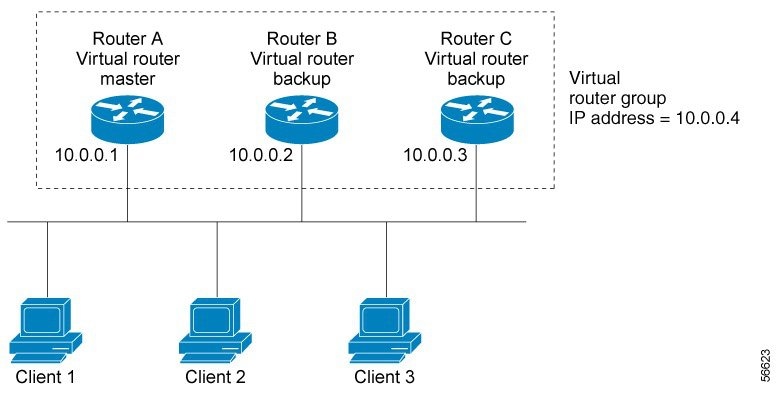
Because the virtual router uses the IP address of the physical Ethernet interface of Router A, Router A assumes the role of the virtual router master and is also known as the IP address owner. As the virtual router master, Router A controls the IP address of the virtual router and is responsible for forwarding packets sent to this IP address. Clients 1 through 3 are configured with the default gateway IP address of 10.0.0.1.
Routers B and C function as virtual router backups. If the virtual router master fails, the router configured with the higher priority will become the virtual router master and provide uninterrupted service for the LAN hosts. When Router A recovers, it becomes the virtual router master again. For more detail on the roles that VRRP routers play and what happens if the virtual router master fails, see the VRRP Router Priority and Preemption section.
The figure below shows a LAN topology in which VRRP is configured so that Routers A and B share the traffic to and from clients 1 through 4 and that Routers A and B act as virtual router backups to each other if either router fails.

In this topology, two virtual routers are configured. (For more information, see the Multiple Virtual Router Support section.) For virtual router 1, Router A is the owner of IP address 10.0.0.1 and virtual router master, and Router B is the virtual router backup to Router A. Clients 1 and 2 are configured with the default gateway IP address of 10.0.0.1.
For virtual router 2, Router B is the owner of IP address 10.0.0.2 and virtual router master, and Router A is the virtual router backup to Router B. Clients 3 and 4 are configured with the default gateway IP address of 10.0.0.2.
VRRP Benefits
Redundancy
VRRP enables you to configure multiple routers as the default gateway router, which reduces the possibility of a single point of failure in a network.
Load Sharing
You can configure VRRP in such a way that traffic to and from LAN clients can be shared by multiple routers, thereby sharing the traffic load more equitably among available routers.
Multiple Virtual Routers
Multiple IP Addresses
The virtual router can manage multiple IP addresses, including secondary IP addresses. Therefore, if you have multiple subnets configured on an Ethernet interface, you can configure VRRP on each subnet.
Preemption
The redundancy scheme of VRRP enables you to preempt a virtual router backup that has taken over for a failing virtual primary router with a higher priority virtual router backup that has become available.
Authentication
VRRP message digest 5 (MD5) algorithm authentication protects against VRRP-spoofing software and uses the industry-standard MD5 algorithm for improved reliability and security.
Advertisement Protocol
VRRP uses a dedicated Internet Assigned Numbers Authority (IANA) standard multicast address (224.0.0.18) for VRRP advertisements. This addressing scheme minimizes the number of routers that must service the multicasts and allows test equipment to accurately identify VRRP packets on a segment. The IANA assigned VRRP the IP protocol number 112.
VRRP Object Tracking
VRRP object tracking provides a way to ensure the best VRRP router is the virtual primary router for the group by altering VRRP priorities to the status of tracked objects such as the interface or IP route states.
Multiple Virtual Router Support
-
Router processing capability
-
Router memory capability
-
Router interface support of multiple MAC addresses
In a topology where multiple virtual routers are configured on a router interface, the interface can act as primary for one virtual router and as a backup for one or more virtual routers.
VRRP Router Priority and Preemption
An important aspect of the VRRP redundancy scheme is VRRP router priority. Priority determines the role that each VRRP router plays and what happens if the virtual primary router fails.
If a VRRP router owns the IP address of the virtual router and the IP address of the physical interface, this router will function as a virtual primary router.
Priority also determines if a VRRP router functions as a virtual router backup and the order of ascendancy to becoming virtual primary router if the virtual primary router fails. You can configure the priority of each virtual router backup with a value of 1 through 254 using the vrrp priority command.
For example, if Router A, the virtual primary router in a LAN topology, fails, an election process takes place to determine if virtual router backups B or C should take over. If Routers B and C are configured with the priorities of 101 and 100, respectively, Router B is elected to become virtual primary router because it has the higher priority. If Routers B and C are both configured with the priority of 100, the virtual router backup with the higher IP address is elected to become the virtual primary router.
By default, a preemptive scheme is enabled whereby a higher priority virtual router backup that becomes available takes over for the virtual router backup that was elected to become virtual primary router. You can disable this preemptive scheme using the no vrrp preempt command. If preemption is disabled, the virtual router backup that is elected to become virtual primary router remains as the primary until the original virtual primary router recovers and becomes the primary again.
VRRP Advertisements
The virtual primary router sends VRRP advertisements to other VRRP routers in the same group. The advertisements communicate the priority and state of the virtual primary router. The VRRP advertisements are encapsulated in IP packets and sent to the IP Version 4 multicast address assigned to the VRRP group. The advertisements are sent every second by default; the interval is configurable.
Although the VRRP protocol as per RFC 3768 does not support millisecond timers, Cisco routers allow you to configure millisecond timers. You need to manually configure the millisecond timer values on both the primary and the backup routers. The primary advertisement value displayed in the show vrrp command output on the backup routers is always 1 second because the packets on the backup routers do not accept millisecond values.
You must use millisecond timers where absolutely necessary and with careful consideration and testing. Millisecond values work only under favorable circumstances, and you must be aware that the use of the millisecond timer values restricts VRRP operation to Cisco devices only.
How to Configure VRRP
Configuring VRRP
Customizing the behavior of VRRP is optional. Be aware that as soon as you enable a VRRP group, that group is operating. It is possible that if you first enable a VRRP group before customizing VRRP, the router could take over control of the group and become the virtual primary router before you have finished customizing the feature. Therefore, if you plan to customize VRRP, it is a good idea to do so before enabling VRRP.
Procedure
| Step 1 |
enable Example:Enables privileged EXEC mode.
|
| Step 2 |
configure terminal Example:Enters global configuration mode. |
| Step 3 |
interface type number Example:Enters interface configuration mode. |
| Step 4 |
ip address ip-address mask Example:Configures an IP address for an interface. |
| Step 5 |
vrrp group description text Example:Assigns a text description to the VRRP group. |
| Step 6 |
vrrp group priority level Example:Sets the priority level of the router within a VRRP group.
|
| Step 7 |
vrrp group preempt [delay minimum seconds] Example:Configures the router to take over as virtual primary router for a VRRP group if it has a higher priority than the current virtual primary router.
|
| Step 8 |
vrrp group timers learn Example:Configures the router, when it is acting as virtual router backup for a VRRP group, to learn the advertisement interval used by the virtual primary router. |
| Step 9 |
exit Example:Exits interface configuration mode. |
| Step 10 |
no vrrp sso Example:(Optional) Disables VRRP support of SSO.
|
Enabling VRRP
Procedure
| Step 1 |
enable Example:Enables privileged EXEC mode.
|
||
| Step 2 |
configure terminal Example:Enters global configuration mode. |
||
| Step 3 |
interface type number Example:Enters interface configuration mode. |
||
| Step 4 |
ip address ip-address mask Example:Configures an IP address for an interface. |
||
| Step 5 |
vrrp group ip ip-address [secondary] Example:Enables VRRP on an interface.
|
||
| Step 6 |
show vrrp [brief all] | interface] Example:(Optional) Displays a brief or detailed status of one or all VRRP groups on the router. |
||
| Step 7 |
show vrrp interface type number [brief] Example:(Optional) Displays the VRRP groups and their status on a specified interface. |
||
| Step 8 |
end Example:Returns to privileged EXEC mode. |
Disabling a VRRP Group on an Interface
Disabling a VRRP group on an interface allows the protocol to be disabled, but the configuration to be retained. This ability was added with the introduction of the VRRP MIB, RFC 2787, Definitions of Managed Objects for the Virtual Router Redundancy Protocol .
You can use a Simple Network Management Protocol (SNMP) management tool to enable or disable VRRP on an interface. Because of the SNMP management capability, the vrrp shutdown command was introduced to represent a method via the command line interface (CLI) for VRRP to show the state that had been configured using SNMP.
When the show running-config command is entered, you can see immediately if the VRRP group has been configured and set to enabled or disabled. This is the same functionality that is enabled within the MIB.
The no form of the command enables the same operation that is performed within the MIB. If the vrrp shutdown command is specified using the SNMP interface, then entering the no vrrp shutdown command reenables the VRRP group.
Procedure
| Step 1 |
enable Example:Enables privileged EXEC mode.
|
||
| Step 2 |
configure terminal Example:Enters global configuration mode. |
||
| Step 3 |
interface type number Example:Enters interface configuration mode. |
||
| Step 4 |
ip address ip-address mask Example:Configures an IP address for an interface. |
||
| Step 5 |
vrrp group shutdown Example:Disables the VRRP group on an interface.
|
Configuring VRRP Text Authentication
Before you begin
Interoperability with vendors that may have implemented the RFC 2338 method is not enabled.
Text authentication cannot be combined with MD5 authentication for a VRRP group at any one time. When MD5 authentication is configured, the text authentication field in VRRP hello messages is set to all zeros on transmit and ignored on receipt, provided the receiving router also has MD5 authentication enabled.
Procedure
| Step 1 |
enable Example:Enables privileged EXEC mode.
|
||
| Step 2 |
configure terminal Example:Enters global configuration mode. |
||
| Step 3 |
terminal interface type number Example:Configures an interface type and enters interface configuration mode. |
||
| Step 4 |
ip address ip-address mask [secondary] Example:Specifies a primary or secondary IP address for an interface. |
||
| Step 5 |
vrrp group authentication text text-string Example:Authenticates VRRP packets received from other routers in the group.
|
||
| Step 6 |
vrrp group ip ip-address Example:Enables VRRP on an interface and identifies the IP address of the virtual router. |
||
| Step 7 |
end Example:Returns to privileged EXEC mode. |
Configuring VRRP v3 for IPV4
Fhrp version vrrp v3
Int bdi< >
Vrrp 1 address-family ipv4
Priority 190
Preempt delay minimum 10
Address <ipv4-address> primary
BFD on VRRPv3
|
Feature Name |
Release |
Description |
|---|---|---|
|
Support for BFD, sub-second fast hello for VRRPv3 convergence and re-convergence |
Cisco IOS XE Bengaluru 17.6.1 |
This feature supports VRRP failover such that the fault is detected by the VRRP-BFD client within the configured value – when the connection to the remote interface IP address fails. |
The VRRP BFD Peering feature introduces Bidirectional Forwarding Detection (BFD) in the VRRP group. Only one BFD session is created per IP using the bfd peer <IP> command. The VRRP groups that are configured with the same bfd peer IP, becomes as a client to a common BFD session. You can enable BFD support for VRRP using the fhrp bfd command configuration and it is not enabled by default. The VRRP standby device learns the real IP address of the VRRP active device from the VRRP hello messages. The standby device registers as a BFD client and asks to be notified if the active device becomes unavailable. When BFD determines that the connections between standby and active devices has failed, it notifies VRRP on the standby device which immediately takes over as the active device. BFD provides fast peer failure detection independently.
Use the following commands:
-
To enable BFD on VRRPv3, use the fhrp bfd command.
-
To synchronize VRRP or BFD state between the primary and standby RSPs, use the fhrp sso command.
Restrictions
-
BFD on VRRP is supported only on VRRPv3 groups. For VRRP groups with multiple backup devices, the configuration of BFD peer on each backup device does not create a mesh of peers automatically.
-
The VRRP BFD is designed only for one Primary and one Standby topology.
-
We recommend you to use the BFD template for attaching the BFD timers.
-
While using BFD intervals under interfaces, No bfd echo must be added explicitly.
-
To improve the convergence in multiple ways, use the following commands in your configuration:
-
arp priority-packet enable
-
fhrp delay reload
-
Configuration Examples for VRRPv2
Example: Configuring VRRP
In the following example, Router A and Router B each belong to three VRRP groups.
In the configuration, each group has the following properties:
-
Group 1: - Virtual IP address is 10.1.0.10.
- Router A will become the primary for this group with priority 120.
- Advertising interval is 3 seconds.
- Preemption is enabled.
-
Group 5: - Router B will become the primary for this group with priority 200.
- Advertising interval is 30 seconds.
- Preemption is enabled.
-
Group 100: - Router A will become the primary for this group first because it has a higher IP address (10.1.0.2).
- Advertising interval is the default 1 second.
- Preemption is disabled.
Router A
Router(config)#
Router(config)# interface BDI <interface number>
Router(config-if)# ip address 10.1.0.2 255.0.0.0
Router(config-if)# vrrp 1 priority 120
Router(config-if)# vrrp 1 authentication text cisco
Router(config-if)# vrrp 1 timers advertise 3
Router(config-if)# vrrp 1 timers learn
Router(config-if)# vrrp 1 ip 10.1.0.10
Router(config-if)# vrrp 5 priority 100
Router(config-if)# vrrp 5 timers advertise 30
Router(config-if)# vrrp 5 timers learn
Router(config-if)# vrrp 5 ip 10.1.0.50
Router(config-if)# vrrp 100 timers learn
Router(config-if)# no vrrp 100 preempt
Router(config-if)# vrrp 100 ip 10.1.0.100
Router(config-if)# no shutdown
Router B
Router(config)# BDI <interface number>
Router(config-if)# ip address 10.1.0.1 255.0.0.0
Router(config-if)# vrrp 1 priority 100
Router(config-if)# vrrp 1 authentication text cisco
Router(config-if)# vrrp 1 timers advertise 3
Router(config-if)# vrrp 1 timers learn
Router(config-if)# vrrp 1 ip 10.1.0.10
Router(config-if)# vrrp 5 priority 200
Router(config-if)# vrrp 5 timers advertise 30
Router(config-if)# vrrp 5 timers learn
Router(config-if)# vrrp 5 ip 10.1.0.50
Router(config-if)# vrrp 100 timers learn
Router(config-if)# no vrrp 100 preempt
Router(config-if)# vrrp 100 ip 10.1.0.100
Router(config-if)# no shutdown
Example: VRRP Text Authentication
The following example shows how to configure VRRP text authentication using a text string:
Router(config)# BDI <interface number>
Router(config)# ip address 10.21.8.32 255.255.255.0
Router(config-if)# vrrp 10 authentication text stringxyz
Router(config-if)# vrrp 10 ip 10.21.8.10
Example: Disabling a VRRP Group on an Interface
The following example shows how to disable one VRRP group on BDI Interface while retaining VRRP for group 2 on the BDI interface:
Router(config)# BDI <interface number>
Router(config-if)# ip address 10.24.1.1 255.255.255.0
Router(config-if)# vrrp 1 ip 10.24.1.254
Router(config-if)# vrrp 1 shutdown
Router(config-if)# exit
Router(config)#  BDI <interface number>
Router(config-if)# ip address 10.168.42.1 255.255.255.0
Router(config-if)# vrrp 2 ip 10.168.42.254
Example: Configuring VRRP BFD Peer
The following example shows how to configure VRRP BFD peer.
Router#config terminal
/* Enter configuration commands, one per line. End with CNTL/Z. */
Router(config)#int bdi 101
Router(config-if)#ip add 99.97.5.2 255.255.255.0
Router(config-if)#bfd template 100ms
Router(config-if)#vrrp 105 address-family ipv4
Router(config-if-vrrp)#address 99.97.5.200 primary
Router(config-if-vrrp)#priority 200
Router(config-if-vrrp)#bfd ?
  peer  BFD peer configuration
Router(config-if-vrrp)#bfd peer ?
  A.B.C.D  IP address
Router(config-if-vrrp)#bfd peer 99.97.5.1
Router(config-if-vrrp)#end
Verifying VRRP BFD Peer
To verify the BFD peering information, use the following command in EXEC mode. Also, you can use the show vrrp neighbor command to list the number of sessions per neighbor basis.
Router#show vrrp bfd
  Interface          Grp  A-F Handle Reference       Peer address        State
  BD51               103 IPv4   1        1                 99.97.3.1       UP
  BD76               104 IPv4   2        1                 99.97.4.1       UP
  BD101              105 IPv4   3        1                 99.97.5.1       UP
  BD126              106 IPv4   4        1                 99.97.6.1       UP

Router#show vrrp bfd bdi101
  Interface          Grp  A-F Handle Reference       Peer address        State
  BD101              105 IPv4   3        1                 99.97.5.1       UP
Example: Configuring VRRP IPv6 Link Local Groups
The following example shows how to configure VRRP IPv6 link local groups.
Router(config)#interface bdi 2
Router(config)# bfd template 100ms
Router(config-if)#vrrp 1 address-family ipv6
Router(config-if-vrrp)#address fe80::100 primary
Router(config-if-vrrp)# priority 200
Router(config-if-vrrp)#bfd peer ?
  X:X:X:X::X          IPv6 link-local address
  X:X:X:X::X/<0-128>  IPv6 address and prefix

Router(config-if-vrrp)#bfd peer fe80::4
Verifying VRRP IPv6 Link Local Groups
To verify the IPv6 link local group information, use the following command in EXEC mode:
Router#show vrrp brief
  Interface          Grp  A-F Pri  Time Own Pre State   Master addr/Group             addr
  BD2                  1 IPv6 200     0  N   Y     MASTER    FE80::3(local)          FE80::100

Router#show vrrp bfd
  Interface          Grp  A-F Handle Reference      Peer address        State
    BD2                1 IPv6         2        1    FE80::4                UP
Example: Configuring VRRP for Global IPv6 Groups
The following example shows how to configure VRRP for global IPv6 groups.
Router(config)#interface bdi 3
Router(config)#bfd template 100ms
Router(config-if)#no sh
Router(config-if)#ipv6 address 27::2/64
Router(config-if)#ipv6 address fe80::1:2 link-local
Router(config-if)#vrrp 1 address-family ipv6
Router(config-if-vrrp)#address fe80::1:100 primary
Router(config-if-vrrp)#address 27::100/64
Router(config-if-vrrp)#bfd peer ?
  X:X:X:X::X          IPv6 link-local address
  X:X:X:X::X/<0-128>  IPv6 address and prefix

Router(config-if-vrrp)#bfd peer 27::3/64
Verifying VRRP for Gloabal IPv6 Groups
To verify the global IPv6 information, use the following command in EXEC mode:
Router#show vrrp brief
Interface       Grp  A-F Pri  Time Own Pre State   Master addr/Group addr
BD3               1  IPv6 100   0  N   Y  MASTER  FE80::1:2(local) FE80::1:100


Router#show vrrp bfd
  Interface          Grp  A-F Handle Reference       Peer address        State
    BD3                1IPv6   4        1                27::3           UP
 Feedback