The documentation set for this product strives to use bias-free language. For the purposes of this documentation set, bias-free is defined as language that does not imply discrimination based on age, disability, gender, racial identity, ethnic identity, sexual orientation, socioeconomic status, and intersectionality. Exceptions may be present in the documentation due to language that is hardcoded in the user interfaces of the product software, language used based on RFP documentation, or language that is used by a referenced third-party product. Learn more about how Cisco is using Inclusive Language.
ITU-T Y.1731 Performance
Monitoring in a Service Provider Network
ITU-T Y.1731
performance monitoring provides standard-based Ethernet performance monitoring
that encompasses the measurement of Ethernet frame delay, frame-delay
variation, and throughput as outlined in the ITU-T Y.1731 specification and
interpreted by the Metro Ethernet Forum (MEF). Service providers offer service
level agreements (SLAs) that describe the level of performance customers can
expect for services. This document describes the Ethernet performance
management aspect of SLAs.
Prerequisites for ITU-T Y.1731 Performance Monitoring in a Service Provider Network
For Y.1731 performance monitoring to work, connectivity fault management (CFM) sessions should be up and running.
Continuity check messages (CCM) database should be populated.
Restrictions for ITU-T Y.1731 Performance Monitoring in a Service Provider Network
Y.1731 performance monitoring supports only synthetic loss measurement (SLM) and two-way delay measurement (DMM).
Y.1731 performance monitoring does not support one-way frame-delay measurement (1DM), loss measurement management (LMM) and
clocksync.
Y.1731 performance monitoring sessions cannot be initiated from port maintenance end points (port-MEP) and trunk ethernet
flow points (trunk EFP).
It is not recommended to change the default frame interval and frame sizes in Y.1731 performance monitoring. Default frame
interval of only 1000 ms is supported.
Maximum number of Y.1731 performance monitoring sessions supported is 100.
While Y.1731 performance monitoring sessions are running, it is not recommneded to perform dynamic encapsulation modification.
Y.1731 performance monitoring over CFM encapsulation default/untagged should have cos bit set to zero.
Y1731 performance monitoring is not supported if the core dot1ad nni interface is configured as trunk.
Information About ITU-T Y.1731 Performance Monitoring in a Service Provider Network
Frame Delay and Frame-Delay
Variation
The Frame Delay
parameter can be used for on-demand OAM measurements of frame delay and
frame-delay variation. When a maintenance end point (MEP) is enabled to
generate frames with frame-delay measurement (ETH-DM) information, it
periodically sends frames with ETH-DM information to its peer MEP in the same
maintenance entity. Peer MEPs perform frame-delay and frame-delay variation
measurements through this periodic exchange during the diagnostic interval.
An MEP requires the
following specific configuration information to support ETH-DM:
MEG level—MEG
level at which the MEP exists
Priority
Transmission rate
Total interval of
ETH-DM
A MEP transmits
frames with ETH-DM information using the TxTimeStampf information element.
TxTimeStampf is the time stamp for when the ETH-DM frame was sent. A receiving
MEP can compare the TxTimeStampf value with the RxTimef value, which is the
time the ETH-DM frame was received, and calculate one-way delay using the
formula
frame delay =
RxTimef – TxTimeStampf.
One-way frame-delay
measurement (1DM) requires that clocks at both the transmitting MEP and the
receiving MEPs are synchronized. Measuring frame-delay variation does not
require clock synchronization and the variation can be measured using 1DM or a
frame-delay measurement message (DMM) and a frame-delay measurement reply (DMR)
frame combination.
If it is not
practical to have clocks synchronized, only two-way frame-delay measurements
can be made. In this case, the MEP transmits a frame containing ETH-DM request
information and the TxTimeStampf element, and the receiving MEP responds with a
frame containing ETH-DM reply information and the TxTimeStampf value copied
from the ETH-DM request information.
Two-way frame delay is calculated as (RxTimeb–TxTimeStampf)–(TxTimeStampb–RxTimeStampf), where RxTimeb is the time that the frame with ETH-DM reply information was received. Two-way frame delay and variation can
be measured using only DMM and DMR frames.
To allow more precise
two-way frame-delay measurement, the MEP replying to a frame with ETH-DM
request information can also include two additional time stamps in the ETH-DM
reply information:
RxTimeStampf—Time
stamp of the time at which the frame with ETH-DM request information was
received.
TxTimeStampb—Time
stamp of the time at which the transmitting frame with ETH-DM reply information
was sent.
The timestamping happens at the hardware level for DMM operations.
Note
The frame-loss, frame-delay, and frame-delay variation measurement processes are terminated when faults related to continuity
and availability occur or when known network topology changes occur.
An MIP is transparent
to the frames with ETH-DM information; therefore, an MIP does not require
information to support the ETH-DM function.
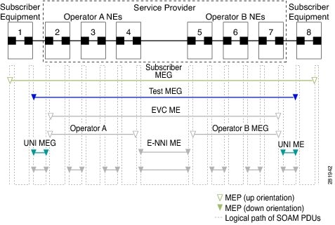
The figure below
shows a functional overview of a typical network in which Y.1731 performance
monitoring is used.
Figure 1. Y.1731
Performance Monitoring
Frame Loss
Ratio
Ethernet Frame Loss
Ratio (ETH-LM: FLR), also known as frame loss, measures the availability of
synthetic frames in the network. Availability is defined in terms of the ratio
of frames lost to frames sent, or Frame Loss Ratio (FLR).
Ethernet Synthetic
Loss Measurement (ETH-SLM) is used to collect counter values applicable for
ingress and egress synthetic frames where the counters maintain a count of
transmitted and received synthetic frames between a pair of MEPs.
ETH-SLM transmits
synthetic frames with ETH-SLM information to a peer MEP and similarly receives
synthetic frames with ETH-SLM information from the peer MEP. Each MEP performs
frame loss measurements, which contribute to unavailable time. A near-end frame
loss refers to frame loss associated with ingress data frames. A far-end frame
loss refers to frame loss associated with egress data frames. Both near-end and
far-end frame loss measurements contribute to near-end severely errored seconds
and far-end severely errored seconds, which together contribute to unavailable
time. ETH-SLM is measured using SLM and SLR frames.
There are the two methods of frame loss measurement, defined by the ITU-T Y.1731 standard ETH-LM and ETH-SLM. However, the
Cisco NCS 520 router supports only single-ended ETH-SLM.
Single-ended
ETH-SLM
Each MEP transmits
frames with the ETH-SLM request information to its peer MEP and receives frames
with ETH-SLR reply information from its peer MEP to carry out synthetic loss
measurements.
Benefits of ITU-T Y.1731 Performance Monitoring
Combined with IEEE-compliant connectivity fault management (CFM), Y.1731 performance monitoring provides a comprehensive
fault management and performance monitoring solution for service providers. This comprehensive solution in turn lessens service
providers’ operating expenses, improves their service-level agreements (SLAs), and simplifies their operations.
How to Configure ITU-T Y.1731 Performance Monitoring in a Service Provider Network
Configuring Ethernet Two-Way Delay Measurement
Procedure
Command or Action
Purpose
Step 1
enable
Example:
Device> enable
Enables privileged EXEC mode.
Enter your password if prompted.
Step 2
configureterminal
Example:
Device# configure terminal
Enters global configuration mode.
Step 3
ipslaoperation-number
Example:
Device(config-term)# ip sla 10
Begins configuring an IP SLAs operation and enters IP SLA configuration mode.
Router(config)# ip sla reaction-configuration 11 react unavailableDS
(Optional) Configures proactive threshold monitoring for frame loss measurements.
operation-number—Identifies the IP SLAs operation for which reactions are to be configured.
react—(Optional) Specifies the element to be monitored for threshold violations.
unavailableDS—Specifies that a reaction should occur if the percentage of destination-to-source Frame Loss Ratio (FLR) violates the upper
threshold or lower threshold.
unavailableSD—Specifies that a reaction should occur if the percentage of source-to-destination FLR violates the upper threshold or lower
threshold.
loss-ratioDS—Specifies that a reaction should occur if the one-way destination-to-source loss-ratio violates the upper threshold or lower
threshold.
loss-ratioSD—Specifies that a reaction should occur if the one way source-to-destination loss-ratio violates the upper threshold or lower
threshold.
threshold-type average[ number-of-measurements]—(Optional) When the average of a specified number of measurements for the monitored element exceeds the upper threshold
or when the average of a specified number of measurements for the monitored element drops below the lower threshold, perform
the action defined by the action-type keyword. The default number of 5 averaged measurements can be changed using the number-of-measurements
argument. The range is from 1 to 16.
threshold-type consecutive[occurrences] —(Optional) When a threshold violation for the monitored element is met consecutively for a specified number of times, perform
the action defined by the action-type keyword. The default number of 5 consecutive occurrences can be changed using the occurrences
argument. The range is from 1 to 16.
threshold-type immediate—(Optional) When a threshold violation for the monitored element is met, immediately perform the action defined by the action-type keyword.
threshold-valueupper-threshold lower-threshold—(Optional) Specifies the upper-threshold and lower-threshold values of the applicable monitored elements.
Step 13
ip sla logging traps
Example:
Router(config)# ip sla logging traps
(Optional) Enables IP SLAs syslog messages from CISCO-RTTMON-MIB.
Step 14
exit
Example:
Router(config)# exit
Exits global configuration mode and enters privileged EXEC mode.
What to do next
Once the SLM is configured, you have to schedule an IP SLA operation.
Scheduling an IP SLA Operation
To schedule an IP SLA operation, execute the following commands:
Procedure
Step 1
enable
Example:
Router> enable
Enables the privileged EXEC mode.
Enter your password if prompted.
Step 2
configure terminal
Example:
Router# configure terminal
Enters the global configuration mode.
Step 3
ip sla scheduleoperation-number [ life { forever | seconds }] [start-time {hh: mm [: ss] [month day | day month] | pending | now | afterhh: mm: ss | randommilliseconds}]
Example:
Router(config)# ip sla schedule 10 start-time now life forever
Configures the scheduling parameters for an individual IP SLA operation or Specifies an IP SLA operation group number and
the range of operation numbers to be scheduled for a multi-operation scheduler.
operation-number—Identifies the IP SLAs operation for which reactions are to be configured.
life forever— (Optional) Schedules the operation to run indefinitely.
lifeseconds —(Optional) Number of seconds the operation actively collects information. The default is 3600 seconds (one hour).
start-time—(Optional) Time when the operation starts.
hh:mm[:ss] —Specifies an absolute start time using hour, minute, and (optionally) second. Use the 24-hour clock notation. For example,
start-time 01:02 means “start at 1:02 a.m.,” and start-time 13:01:30 means “start at 1:01 p.m. and 30 seconds.” The current
day is implied unless you specify a month and day.
month—(Optional) Name of the month to start the operation in. If month is not specified, the current month is used. Use of this
argument requires that a day be specified. You can specify the month by using either the full English name or the first three
letters of the month.
day—(Optional) Number of the day (in the range 1 to 31) to start the operation on. If a day is not specified, the current day
is used. Use of this argument requires that a month be specified.
pending—(Optional) No information is collected. This is the default value.
now—(Optional) Indicates that the operation should start immediately.
after hh:mm:ss—(Optional) Indicates that the operation should start hh hours, mm minutes, and ss seconds after this command was entered.
random milliseconds—(Optional) Adds a random number of milliseconds (between 0 and the specified value) to the current time, after which the
operation will start. The range is from 0 to 10000.
Step 4
exit
Example:
Router(config)# exit
Exits the global configuration mode and enters the privileged EXEC mode.

 Feedback