- Preface
- Cisco NCS 4016 System Features
- Establish Connection to a Node
- Install and Login to Cisco Transport Controller
- Bring-up the Node for Network Connectivity
- Perform Preliminary Checks
- Create User Profiles and Assign Privileges
- Perform System Upgrade and Install Feature Packages
- Perform Disaster Recovery
Perform Disaster Recovery
The topics covered in this chapter are:
Create a Bootable USB Drive
The bootable USB drive is used to re-image the router for the purpose of system upgrade or boot the router in case of boot failure. The bootable USB drive can be created in two ways:
Create a Bootable USB Drive Using Compressed Boot File (applicable to Cisco IOS XR Software Release 5.0.1)
- Create a Bootable USB Drive Using Compressed Boot File
- Create a Bootable USB Drive Using Shell Script
Create a Bootable USB Drive Using Compressed Boot File
A bootable USB drive is created by copying a compressed boot file into a USB drive. The USB drive becomes bootable after the contents of the compressed file are extracted.
This task can be completed using Windows, Linux, or MAC operating systems available on your local machine. The exact operation to be performed for each generic step outlined here depends on the operating system in use.
-
Have access to a USB drive with a storage capacity that is between 2GB (min) and 32 GB (max). USB 2.0 and USB 3.0 are supported.
-
Copy the compressed boot file from the software download page at cisco.com to your local machine. The file name for the compressed boot file is in the format ncs4k-usb-boot-<release_number>.zip. For example, ncs4k-usb-boot-5.2.3.zip.
1. Connect the USB drive to your local machine and format it with FAT32 file system.
2. Copy the compressed boot file to the USB drive.
3. Unzip the compressed boot file inside the USB drive.
4. The contents of the compressed boot file ("EFI" and "Boot" directories) should be extracted to the root of the USB drive. If they are extracted to a separate folder, move them to the root of the USB drive.
DETAILED STEPS
What to Do Next
Use the bootable USB drive to boot the router or upgrade its image. See:
Create a Bootable USB Drive Using Shell Script
To create the bootable USB drive using shell script, you need an ISO image file and the shell script that creates the boot device. The shell script is available on the router itself. Create the bootable USB drive as an preemptive measure when the router is operational. If router is already unusable, create the bootable USB drive on another active router or as instructed in the procedure Create a Bootable USB Drive Using Compressed Boot File.
 Note | The contents of the USB drive is erased during the process of creating the bootable drive. |
1.
copy
tftp:source
disk1:destination
2.
dir /disk1:
3.
run ls
/usr/bin/usb-install.sh
4. Connect the USB drive.
5.
run
6.
tail /var/log/messages
7.
cd
directory
path
8.
<shell_script_file_name>
<location_of_iso_image>
<mount_location_of_USB_device>
DETAILED STEPS
What to Do Next
Use the bootable USB drive to boot the router or upgrade its image. See:
Boot the Router Using USB
The router can be booted using an external bootable USB drive. This might be required when the router is unable to boot from the installed image. Boot failure can happen when the image gets corrupted. During the USB boot process the router gets re-imaged with the version available on the USB drive.
The default boot sequence is USB disk, Sata disk and PXE boot.
Note |
|
-
Create a bootable USB drive. See Create a Bootable USB Drive Using Shell Script or Create a Bootable USB Drive Using Compressed Boot File based on requirement.
-
Ensure that an external connection unit (ECU) with two solid-state drives (SSDs) are present.
| Step 1 | Connect the USB
drive to an RP.
The USB port on the RP is shown in this figure. 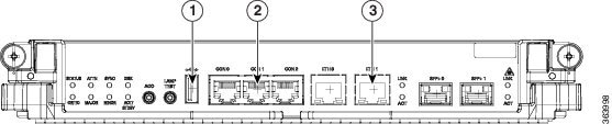
| ||||||
| Step 2 | Connect to the
console.
If it is not already connected, connect a terminal to the System Admin console port of the RP. If two RPs are installed on the router, connect to the System Admin console port of both RPs. Start the terminal emulation program on your workstation. | ||||||
| Step 3 | Power on the router. | ||||||
| Step 4 | Press F12 on the
console of the RP to which the USB is not connected. This action displays the
boot menu and pauses the boot process. The RP on which the USB is connected
should boot normally.
Only the RP having the USB should boot. The booting of other RP is paused. | ||||||
| Step 5 | Select the USB
drive to boot from USB.
According to the default boot sequence, the USB drive is the first boot source. Because the USB device is already connected, the router automatically boots from it. During the boot process, the OS image is installed on the router so that in future the router boots without the USB. According to the default boot sequence, the Sata disk is the first boot source and the USB drive is the second boot source. During the boot process, the OS image is installed on the router so that in future the router boots without the USB. | ||||||
| Step 6 | Remove the USB
drive.
Running install image: Please reboot the systemOn receiving this message, remove the USB drive.
| ||||||
| Step 7 | Press Enter to get the host prompt. | ||||||
| Step 8 | Login to the
host using
root and
lab as
username and password respectively.
Example: host login: root Password: If there is no space in the RP, a prompt to either abort installation or to continue with formatting the disk is displayed. [Install image, reboot required host:~]$ | ||||||
| Step 9 | Run the
reboot
command.
Example: [Install image, reboot required host:~]$ reboot The RP reboots with the new image. After the booting is completed, specify the root-system username and password. For details, see Setup Root User Credentials and Login to XR VM Console. | ||||||
| Step 10 | Access the
System Admin EXEC mode and
reload the RP for which the boot process was paused in Step 4.
Example: sysadmin-vm:0_RP0#hw-module location 0/RP1 reload
The shut down RP is reloaded and gets synchronized with the other RP running the new image. |
What to Do Next
-
After the booting process is complete, specify the root username and password. For details, see Setup Root User Credentials and Login to XR VM Console.
-
Install the required optional packages.
Perform System Upgrade Using USB
The router image can be upgraded using an external bootable USB drive. This might be required when the router is to be re-imaged, but the ISO image cannot be accessed over the network. It can happen when network connectivity is unavailable.
Note | During the upgrade all existing configurations are deleted because the disk 0 content is erased. |
-
Create a bootable USB drive. See Create a Bootable USB Drive Using Shell Script or Create a Bootable USB Drive Using Compressed Boot File based on requirement.
-
Ensure that the router BIOS version is 14.xx or higher.
-
Verify the BIOS version using the show fpd package command in the System Admin EXEC mode.
-
Verify the actual state of all FPGA of the system and whether it require an upgrade or not using the show hw-module fpd command in System Admin EXEC mode.
-
If required, upgrade the BIOS using the upgrade hw-module location all fpd BIOS\ FPD command in the System Admin EXEC mode.
-
| Step 1 | hw-module location
node-id
shutdown
Example: sysadmin-vm:0_RP0#hw-module location 0/RP1 shutdown
Shut down one RP. In this example, the RP1 is shut down. During the system upgrade, only one RP should be operational. | ||||||
| Step 2 | Connect the USB
drive.
The USB drive must be connected to the USB port on the operational RP. The USB port is shown in this figure.
| ||||||
| Step 3 | hw-module
location
node-id
reload
Example: sysadmin-vm:0_RP0#hw-module location 0/RP0 reload
Reload the RP on which the USB is connected. As the RP reloads, it boots from the USB drive and gets re-imaged. | ||||||
| Step 4 | Remove the USB
drive.
Running install image: Please reboot the systemOn receiving this message, remove the USB drive.
| ||||||
| Step 5 | Press Enter to get the host prompt. | ||||||
| Step 6 | Login to the
host using
root and
lab as
username and password respectively.
Example: host login: root Password: [Install image, reboot required host:~]$ | ||||||
| Step 7 | Run the
reboot command.
Example: [Install image, reboot required host:~]$ reboot The RP reboots with the new image. After the booting is completed, specify the root-system username and password. For details, see Setup Root User Credentials and Login to XR VM Console. | ||||||
| Step 8 | Access the
System Admin EXEC mode and
reload the RP that was shut down in Step 1.
Example: sysadmin-vm:0_RP0#hw-module location 0/RP1 reload
The shut down RP is reloaded and gets synchronized with the other RP running the new image. |
What to Do Next
 Feedback