- Preface
- Overview
- Installing and Removing Power Components
- Installing and Removing Air Circulation Components
- Installing and Removing SFCs, RPs, MSCs, FPs, LSPs, PLIMs, and Associated Components
- Installing and Removing the Front Doors and Grille
- Cisco CRS 4-Slot Line Card Chassis System Specifications
- Index
Cisco CRS Carrier Routing System 4-Slot Line Card Chassis Installation Guide
Bias-Free Language
The documentation set for this product strives to use bias-free language. For the purposes of this documentation set, bias-free is defined as language that does not imply discrimination based on age, disability, gender, racial identity, ethnic identity, sexual orientation, socioeconomic status, and intersectionality. Exceptions may be present in the documentation due to language that is hardcoded in the user interfaces of the product software, language used based on RFP documentation, or language that is used by a referenced third-party product. Learn more about how Cisco is using Inclusive Language.
- Updated:
- April 8, 2011
Chapter: Installing and Removing the Front Doors and Grille
Installing and Removing the Doors and Grille
This chapter provides instructions on how to install and remove the front doors and inlet grille on the Cisco CRS Carrier Routing System 4-Slot Line Card Chassis.
This chapter presents the following topics:
•![]() Overview of the Exterior Components
Overview of the Exterior Components
Overview of the Exterior Components
Exterior cosmetic components for the Cisco CRS 4-slot line card chassis are not required to be installed; they are provided as optional components (except for the cable management bracket, which is preinstalled). The the Cisco CRS 4-slot line card chassis is shipped with the following exterior components:
•![]() Cable management bracket—Shipped preinstalled on the chassis.
Cable management bracket—Shipped preinstalled on the chassis.
•![]() Inlet grille—If the cosmetic kit was ordered, the inlet grille is included in the door kit.
Inlet grille—If the cosmetic kit was ordered, the inlet grille is included in the door kit.
•![]() Front doors—Cisco CRS 4-Slot Line Card Chassis Front Door kit (Cisco product number: CRS-4-DOOR-KIT=)
Front doors—Cisco CRS 4-Slot Line Card Chassis Front Door kit (Cisco product number: CRS-4-DOOR-KIT=)
Installing the Inlet Grille
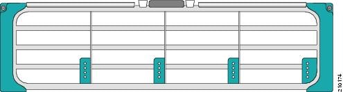
This section describes how to install the inlet grille. The inlet grille covers the power supply and air intake areas at the bottom of the front side of the chassis, just below the card cage.
Figure 5-1 shows the inlet grille.
Figure 5-1 Inlet Grille
Prerequisites
There are no prerequisites for installing the inlet grille.
Required Tools and Equipment
You need the following tools and part to perform this task:
•![]() ESD-preventive wrist strap
ESD-preventive wrist strap
•![]() Inlet grille
Inlet grille
•![]() Number 2 flat screwdriver
Number 2 flat screwdriver
Steps
To install the inlet grille, follow these steps:
Step 1 ![]() Remove the inlet grille from its packaging, then set the packaging aside.
Remove the inlet grille from its packaging, then set the packaging aside.
The inlet grille is packaged in the door assembly box.
Step 2 ![]() Attach the ESD-preventive wrist strap to your wrist and connect its leash to an ESD connection socket on the front side or a bare metal surface on the chassis.
Attach the ESD-preventive wrist strap to your wrist and connect its leash to an ESD connection socket on the front side or a bare metal surface on the chassis.
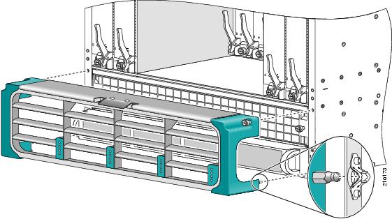
Step 3 ![]() Align the ball studs at the bottom of the inlet grille with the cutouts at the bottom of the chassis casing on the front side of the chassis, just in front of the power supplies (see Figure 5-2).
Align the ball studs at the bottom of the inlet grille with the cutouts at the bottom of the chassis casing on the front side of the chassis, just in front of the power supplies (see Figure 5-2).
Step 4 ![]() Push the inlet grille toward the chassis, and snap the ball studs into place.
Push the inlet grille toward the chassis, and snap the ball studs into place.
Step 5 ![]() Make sure you align the light pipes to the corresponding openings in the power filter.
Make sure you align the light pipes to the corresponding openings in the power filter.
Step 6 ![]() With a Number 2 flat screwdriver, tighten the two captured screws at the upper right and left corners of the grille.
With a Number 2 flat screwdriver, tighten the two captured screws at the upper right and left corners of the grille.
Figure 5-2 Aligning the Inlet Grille
What to Do Next
You can now install the doors (see the "Installing the Doors" section).
Removing the Inlet Grille
This section describes how to remove the inlet grille. The grille covers the power module and air intake areas at the bottom of the front (PLIM) side of the chassis, just below the card cage.
Prerequisites
No prerequisites exist for this task.
Required Tools and Equipment
You need the following tools to perform this task:
•![]() ESD-preventive wrist strap
ESD-preventive wrist strap
•![]() Number 2 flat screwdriver
Number 2 flat screwdriver
Steps
To remove the inlet grille, follow these steps:
Step 1 ![]() Attach the ESD-preventive wrist strap to your wrist and connect its leash to an ESD connection socket on the front side or a bare metal surface on the chassis.
Attach the ESD-preventive wrist strap to your wrist and connect its leash to an ESD connection socket on the front side or a bare metal surface on the chassis.
Step 2 ![]() If the doors have been installed, open the doors to get complete access to the grille.
If the doors have been installed, open the doors to get complete access to the grille.
Step 3 ![]() Using the Number 2 flat-blade screwdriver, unscrew the two captured screws at the upper right and left corners of the grille.
Using the Number 2 flat-blade screwdriver, unscrew the two captured screws at the upper right and left corners of the grille.
Step 4 ![]() Firmly grasp the outside edges of the inlet grille.
Firmly grasp the outside edges of the inlet grille.
Step 5 ![]() Pull the bottom of the grille firmly away from the chassis; it loosens from the connecting ball studs.
Pull the bottom of the grille firmly away from the chassis; it loosens from the connecting ball studs.
Step 6 ![]() Carefully set the inlet grille aside.
Carefully set the inlet grille aside.
Installing the Doors
This section describes how to install the doors on the Cisco CRS 4-slot chassis. We recommend that you install the doors when the chassis has been mounted into its rack.
Prerequisites
Before you install the doors on the Cisco CRS 4-slot chassis, you must install the grille as described above.
Required Tools and Equipment
You need the following tool and parts to perform this task:
•![]() ESD-preventive wrist strap
ESD-preventive wrist strap
•![]() Left and right doors (Cisco product number: CRS-4-DOOR-KIT)
Left and right doors (Cisco product number: CRS-4-DOOR-KIT)
Steps
To install the doors on the Cisco CRS 4-slot chassis, follow these steps:
Step 1 ![]() Remove the door from its packaging (including the protective film that covers each door), and set the packaging aside.
Remove the door from its packaging (including the protective film that covers each door), and set the packaging aside.
Step 2 ![]() Attach the ESD-preventive wrist strap to your wrist and connect its leash to an ESD connection socket or a bare metal surface on the chassis.
Attach the ESD-preventive wrist strap to your wrist and connect its leash to an ESD connection socket or a bare metal surface on the chassis.
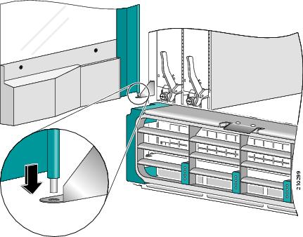
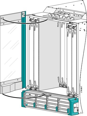
Step 3 ![]() Starting with the left door, align the bottom guide pin over the hole in the lower door mounting bracket (see Figure 5-3).
Starting with the left door, align the bottom guide pin over the hole in the lower door mounting bracket (see Figure 5-3).
Step 4 ![]() Drop the door's bottom guide pin into the lower door mounting bracket hole (see Figure 5-3).
Drop the door's bottom guide pin into the lower door mounting bracket hole (see Figure 5-3).
Figure 5-3 Setting the Door Into the Lower Door Mounting Bracket
Step 5 ![]() Now secure the upper portion of the door. Keeping the door steady with one hand, align the door groove (on the upper inside portion of the door) with the upper door mounting bracket (see Step 1 in Figure 5-4).
Now secure the upper portion of the door. Keeping the door steady with one hand, align the door groove (on the upper inside portion of the door) with the upper door mounting bracket (see Step 1 in Figure 5-4).
Step 6 ![]() Pull the knob latch out, then lift the knob latch up so that the securing pin clears the upper door mounting bracket (see Step 2 in Figure 5-4).
Pull the knob latch out, then lift the knob latch up so that the securing pin clears the upper door mounting bracket (see Step 2 in Figure 5-4).
Figure 5-4 Using the Knob Latch to Secure the Top of the Door
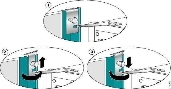

Tip ![]() Observe that there is a guide pin on top of the knob latch.
Observe that there is a guide pin on top of the knob latch.
Step 7 ![]() Keeping the knob latch at a shallow angle, align the securing pin and guide pin with the upper door mounting bracket.
Keeping the knob latch at a shallow angle, align the securing pin and guide pin with the upper door mounting bracket.

Note ![]() You must align both the knob latch and the guide pin before the securing pin will drop properly.
You must align both the knob latch and the guide pin before the securing pin will drop properly.
Step 8 ![]() Pull the knob out, then drop the securing pin into the mounting bracket (see Step 3 in Figure 5-4).
Pull the knob out, then drop the securing pin into the mounting bracket (see Step 3 in Figure 5-4).
Step 9 ![]() To close the door, lift the latch button at the base of the door (see Figure 5-5), then push the door closed.\
To close the door, lift the latch button at the base of the door (see Figure 5-5), then push the door closed.\
The door will snap closed when the door magnets (on the inside top of the door) snap into place and the latching pin on the bottom of the door falls into the receiving holes on the striker panel (see Figure 5-6).
Step 10 ![]() Repeat this procedure for the right door.
Repeat this procedure for the right door.
Figure 5-5 Lifting the Latch Button to Open the Door
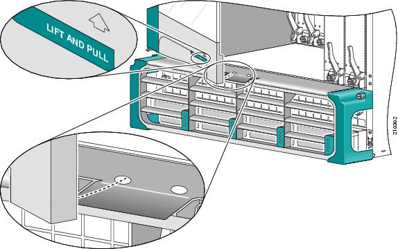
Figure 5-6 Closing the Door
Opening the Doors
To open the doors on the Cisco CRS 4-slot line card chassis, follow these steps:
Step 1 ![]() Lift the latch button at the base of the door (as shown in Figure 5-5).
Lift the latch button at the base of the door (as shown in Figure 5-5).
Step 2 ![]() Pull the door open.
Pull the door open.
Removing the Doors
To remove the doors from the Cisco CRS 4-slot line card chassis, follow these steps:
Step 1 ![]() Open the door you want to remove.
Open the door you want to remove.
Step 2 ![]() While supporting the door with one hand, reach inside the door, pull out the knob latch, then lift the latch out from the upper door mounting bracket.
While supporting the door with one hand, reach inside the door, pull out the knob latch, then lift the latch out from the upper door mounting bracket.
Step 3 ![]() With both hands grasping the door, lift the door out of the lower door mounting bracket.
With both hands grasping the door, lift the door out of the lower door mounting bracket.
Step 4 ![]() Place the door in a safe storage box.
Place the door in a safe storage box.
Step 5 ![]() Repeat this procedure for the other door.
Repeat this procedure for the other door.
 Feedback