High Availability Deployment for IoT FND

This section describes how high availability is achieved for IoT FND:

Overview of High Availability Deployment for IoT FND

IoT FND is a critical application for monitoring and managing a connected grid. This chapter discusses on IoT FND solution High Availability (HA), the different components, how it can be achieved, and what configurations are required to achieve it at various levels.

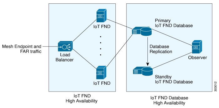
IoT FND provides two main levels of HA:

  • IoT FND Server HA—This is achieved by connecting multiple IoT FND servers to a load balancer. Traffic originating at Mesh Endpoints (ME), Field Area Routers (FAR), and Aggregation Services Routers (ASR) goes to the load balancer, which uses a load balancing algorithm to distribute the load among the IoT FND cluster servers.

  • IoT FND Database HA—This is achieved by configuring two IoT FND Database servers: a primary server and a standby (or secondary) server. When the primary database receives new data it sends a copy to the standby database. A separate system runs the Observer (the Observer can also run on the standby server), which is a program that monitors the IoT FND Database servers. If the primary database fails, the Observer configures the standby server as the new primary database. IoT FND Database HA works in single and cluster IoT FND server deployments.


Note


To set up an Observer server which runs Oracle 12c on a separate server (distinct from the IoT FND Database servers), refer to the following instructions found on the online Oracle Help Center for Oracle 12c (12.1.0.2): Documentation Library.


High Availability Guidelines and Limitations

  • IoT FND HA refers to FND server HA. HA for other IoT FND solution components like FAR, ASR, load balancer etc, has to be considered during design for IoT FND Solution HA.

  • Zero service downtime is targeted by IoT FND HA, but it is not guaranteed.

  • All IoT FND nodes must on the same subnet.

  • All IoT FND nodes must run on similar hardware.

  • All IoT FND nodes must run the same software version.

  • Run the IoT FND setup script (/opt/cgms/bin/setupCgms.sh) on all the nodes.

  • Run the DB migration script (/opt/cgms/bin/db-migrate) on only one node.

  • The /opt/cgms/bin/print_cluster_view.sh script displays information about IoT FND cluster members.

High Availability of IoT FND Solution Components

IoT FND has mandatory components as well as optional components. FND application server itself and the database server form the mandatory components, however, all other components come under optional because some components are required ONLY as per need, for example, Hardware Security Module (HSM) or Software Security Module (SSM) is required only if end points have to be managed.


Note


There are multiple options for IoT FND deployment. IoT FND can also be deployed without tunnels, for example, if you use a private Access Point Name (APN) network or already have a encrypted Multiprotocol Label Switching (MPLS) network for connectivity and choose not to use Tunnel Provisioning Server (TPS) and tunnel provisioning and directly register to IoT FND, in which case, Tunnel High Availability and TPS High Availability might not apply. Also if FND Easy mode is used, then Public Key Infrastructure (PKI) High Availability will not apply.


IoT FND solution components can be classified as below.

FND Solution Component Description

FND Application Server

IoT FND HA is achieved by connecting multiple IoT FND servers to a load balancer. Traffic originating at MEs, FARs, and ASRs goes to the load balancer, and based on the load balancing algorithm, the load balancer distributes the load among the IoT FND cluster servers.

Load Balancer

There can be HA for load balancer as well, which can be discussed with the Load Balancer product vendor, however, this document discusses load balancer in the context of providing HA for FND servers.

Database Server

HA is achieved using Oracle Data Guard, which provides automatic failover between primary and secondary DB servers.

Tunnel High Availability

HA is achieved by using alternate links and/or more than one Head End Router (HER) or FAR.

HER

HER is not managed by IoT FND, but used for tunnel termination. HA is achieved by having multiple HERs.

FAR

FAR redundancy using Hot Standby Router Protocol (HSRP) is supported for the LAN, where one device can act as primary and another can act as secondary router for the LAN and hence for Wireless Personal Area Network (WPAN) components, if the router itself fails.

Note


FAR HA is available only for CGR devices.

TPS

HA is achieved using load balancer which is similar to FND server.

PKI (CA/Sub CA/RA servers)

HA can be achieved by having multiple servers that are clustered or load balanced. There can be manual failover as well. It depends on the PKI vendor and product capabilities.

Note


Please consult your PKI vendor for HA capabilities and implementation.

SSM

Only manual HA is achieved for SSM at the time of release of 4.9.0 FND. SSM is an optional component that is required only if MEs are managed by IoT FND.

HSM

HSM HA can vary. There can be two different HSM servers with one partition on each HSM server. HSM client has to be installed on same RHEL server in which FND server is installed and HSM client also has to be configured appropriately.

Network Requirements for FND HA Setup

  • Ensure that the primary server, the secondary server, and the FND have the network connectivity.

  • The ports 1522 and 1622 must be open in the primary and secondary servers.

FND Server HA

IoT FND Server HA can be achieved by having two or more IoT FND application servers that are balanced using load balancers. Load balancers can take in incoming connections, monitor the load on each IoT FND and serve traffic accordingly.


Note


If there are cgmesh keys, enter these parameters in /opt/cgms/server/cgms/conf/cgms.properties file to fetch mesh keys from the primary CGR in a HA setup.
  • cgr-ha-fetch-mesh-key-attempts = 3 <-- you can modify the number of attempts to fetch the mesh keys

  • cgr-ha-fetch-mesh-key-delay-mins = 1 <-- number of minutes (interval) between mesh-key-attempts


The following configuration is required for IoT FND application server HA.

  • Configure at the /opt/cgms/bin/cgms.conf file that specifies the CLUSTER_BIND_ADDR and UDP_MULTICAST_ADDR

    CLUSTER_BIND_ADDR= a.b.c.d

    UDP_MULTICAST_ADDR= w.x.y.z

    where CLUSTER_BIND_ADDR is the IP address of the server itself and UDP_MULTICAST_ADDR must be the same on all instances. It can be either an IPv4 multicast address or an IPv6 address which is not used in the network.

  • See Certificate Requirements for IoT FND Server HA Deployment for more information on generating certificate for IoT FND server HA deployment.

  • In FND UI, the provisioning settings must point to the cluster VIP IP of the FND servers. For example, if there are fndserver1 and fndserver2, and they are served by fndserverhaVIP.ciscolab.com, then provide it in Admin > System Management > Provisioning Settings.

Load Balancer

The load balancer plays a critical role in IoT FND HA, as it performs these tasks:

  • Load balances traffic destined for IoT FND.

  • Maintains heartbeats with servers in the cluster and detects any failure. If a IoT FND server fails, the load balancer directs traffic to other cluster members. The load balancer maintains heartbeats with each IoT FND server in the cluster.

In the health monitoring mechanism of a load balancer, heartbeats will be sent to each FND server that is load balanced. If response is received within a certain interval and if the response is good, then it is marked as active. However, if response is not received or response received is not the expected response from the FND server, then this FND server is marked down. The load balancer again retries after a specific interval.

The default values for checking the heart beat, the time it takes to retry to mark the server up or down etc, depends on vendor specific implementation for load balancer. Heart beats can be implemented as regular http GET messages to IoT FND server on port 80. IoT FND expects an HTTP 200 OK response from an active IoT FND server. If response is not received within certain period of time, then it is marked down. Some load balancers support custom health monitors to be configured as a user-defined script. In such cases, load balancer can get the response from FND server using the following command.

RHEL Version

Command

8.x

systemctl status cgms

7.x

service cgms status

Example Output:

[root@fndtest ~]# service cgms status
IoT-FND Version 4.8.1-72
09-22-2022 16:45:59 IST: INFO: IoT-FND database server: 1.1.1.1
09-22-2022 16:45:59 IST: INFO: IoT-FND database connection verified.
09-22-2022 16:46:00 IST: INFO: IoT-FND application server is up and running.
09-22-2022 16:46:01 IST: INFO: IoT-FND is up and running.
[root@fndtest ~]#

The user defined script defined in custom health monitor can check if the last 2 lines show as "up and running", that indicates IoT FND application server is up and running.

Load-Balancing Policies

The table describes the load-balancing policy for each type of traffic the LB supports:

Traffic Load Balancing Policy

HTTPS traffic to and from browsers and IoT FND API clients (IPv4; ports 80 and 443)

The LB uses Layer 7 load balancing for all traffic from Web browsers and IoT FND API clients.

The LB uses stickiness for general HTTPS traffic.

For FAR IPv4 traffic going to ports 9121 and 9120:

  • Tunnel Provisioning on port 9120 over HTTPS

  • Regular registration and periodic on 9121 over HTTPS

The LB uses Layer 3 load balancing for all FAR traffic. This is the traffic from the FAR to IoT FND.

For IPv6 CSMP traffic to and from mesh endpoints (MEs):

  • UDP traffic over port 61624

    • Registration

    • Periodic transmission of metrics

    • Firmware push

    • Configuration push

  • UDP traffic over port 61625

    For outage notifications sent by MEs.

The LB uses Layer 3 load balancing for all ME traffic to port 61624, and outage messages to port 61625.

Database High Availability

IoT FND Database HA works in IoT FND single-server and cluster deployments. IoT FND HA uses Oracle Active Dataguard to deploy Oracle HA. To configure HA for the IoT FND Database, use the Oracle Recovery Manager (RMAN) and Dataguard Management CLI (DGMGRL). Helper scripts are provided by Cisco to achieve this deployment of primary and secondary DB, if the DB is set up ONLY for the purpose of IoT FND application.

If Oracle DB is used by other applications as well, then RMAN and DGMGRL can be used to set up the primary and secondary DB, but in this case, the other helper scripts like backup on FND and the restore of FND scripts might not work because the Oracle environment variables will differ.

Oracle DB HA can be achieved whether we have redundancy at the FND server or not. One or more FND servers can connect to the same Database Data Guard cluster.

The IoT FND Database HA configuration process involves:

  • Configuring the primary and secondary databases on separate physical servers or VM.


    Note


    The secondary database server is also referred to as the standby database.

    There is a possibility of losing some data during a database failover.


    Note


    If the primary database fails, the associated standby database becomes the primary database. This is transparent to the IoT FND servers. All IoT FND servers in the cluster connect to the new primary database.


  • Configuring data replication to be performed over SSL using an Oracle wallet. The wallet contains a self-signed certificate to facilitate quick deployment.


    Note


    The Oracle wallet bundled with the IoT FND RPMs uses self-signed certificates. You can configure custom certificates and wallet to facilitate replication.

    There is no performance impact when performing data replication over SSL.


  • Using the sys user for replication and not cgms_dev.

  • Configuring replication as asynchronous to prevent performance bottlenecks.

By default, IoT FND connects to the database using TCP over port 1522. Replication uses TCPS (TCP over SSL) on port 1622.

The scripts for configuring IoT FND Database HA are included in the IoT FND Oracle Database RPM package (cgms-oracle-version_number.x86_64.rpm). When you install the IoT FND Database, the HA scripts are located in $ORACLE_HOME/cgms/scripts/ha.

Setting Up IoT FND Database for HA

To set up the IoT FND Database HA:

Procedure

Step 1

Set up the standby database (see Setting Up the Standby Database).

Note


Always configure the standby database first.

  • The default SID for the standby server is cgms_s and not cgms.

  • Before setting up the standby server for HA, ensure that the environment variable $ORACLE_SID on the standby server is set to cgms_s.

  • The port is always 1522.

Step 2

Set up the primary database (see Setting Up the Primary Database).

The default SID for the primary server is cgms.

Before setting up the primary server for HA, ensure that the environment variable $ORACLE_SID on the primary server is set to cgms.

Step 3

Set up IoT FND for database HA (see Setting Up for IoT FND for Database HA).

Step 4

Set up the database Observer (see Setting Up the Observer).


Setting Up the Standby Database

To set up the standby database server for HA, run the setupStandbyDb.sh script. This script prompts for configuration information needed for the standby database, including the IP address of the primary database.

$ cd $ORACLE_BASE/cgms/scripts/ha
$ ./setupStandbyDb.sh
$ Are you sure you want to setup a standby database ? (y/n)? y
09-20-2012 13:59:18 PDT: INFO: User response: y
09-20-2012 13:59:18 PDT: INFO: CGMS_S database does not exist.
Enter the SYS DBA password. NOTE: This password should be same as the one set on the primary server:
Re-enter password for SYS DBA:
09-20-2012 13:59:58 PDT: INFO: User entered SYS DBA password.
Enter new password for CG-NMS database:
Re-enter new password CG-NMS database:
09-20-2012 14:00:09 PDT: INFO: User entered CG-NMS DB password.
Enter primary database server IP address: 192.168.1.12
09-20-2012 14:00:27 PDT: INFO: Cleaning up instance - cgms_s
DGMGRL for Linux: Version 11.2.0.3.0 - 64bit Production
…
Total System Global Area 329895936 bytes
Fixed Size 2228024 bytes
Variable Size 255852744 bytes
Database Buffers 67108864 bytes
Redo Buffers 4706304 bytes
...
09-20-2012 14:00:29 PDT: INFO: ========== CGMS_S Database Setup Completed Successfully ==========

Setting Up the Primary Database

To set up the primary database server for HA, run the setupHaForPrimary.sh script. This script prompts for configuration information needed for the primary database, including the IP address of the standby database.

$ cd $ORACLE_BASE/cgms/scripts/ha
$ ./setupHaForPrimary.sh
[oracle@pdb ha]$ ./setupHaForPrimary.sh
09-20-2012 13:58:39 PDT: INFO: ORACLE_BASE: /home/oracle/app/oracle
09-20-2012 13:58:39 PDT: INFO: ORACLE_HOME: /home/oracle/app/oracle/product/11.2.0/dbhome_1
09-20-2012 13:58:39 PDT: INFO: ORACLE_SID : cgms
09-20-2012 13:58:39 PDT: INFO: Make sure the above environment variables are what you expect
Are you sure you wish to configure high availability for this database server ? (y/n)? y 
09-20-2012 13:58:45 PDT: INFO: User response: y
Enter standby database server IP address: 192.168.1.10
09-20-2012 13:58:56 PDT: INFO: Secondary listener reachable. Moving on with configuration
mkdir: cannot create directory `/home/oracle/app/oracle/oradata/cgms': File exists
09-20-2012 13:58:58 PDT: INFO: Reloading the listener to pick the new settings
LSNRCTL for Linux: Version 11.2.0.3.0 - Production on 20-SEP-2012 13:58:58
…
DGMGRL> 09-20-2012 14:14:54 PDT: INFO: Please start the 'Observer' on appropriate server for ha
monitoring
Total time taken to perform the operation: 975 seconds
09-20-2012 14:14:54 PDT: INFO: ========== Completed Successfully ==========

Setting Up the Observer

The Observer should run on a separate server, but can be set up on the server hosting the standby database.


Note


The password required for running Observer is the same as the SYS DBA password. See Creating IoT FND Oracle Database topic in Cisco IoT Field Network Director Installation Guide - Oracle Deployment, Releases 4.3.x and Later for more information.


To set up the Observer:

Procedure

Step 1

On a separate server, run the observer script.

$ cd $ORACLE_BASE/cgms/scripts/ha
$ ./manageObserver.sh start cgms_s password
$ DGMGRL for Linux: Version 11.2.0.3.0 - 64bit Production
...
Welcome to DGMGRL, type "help" for information.
DGMGRL> Connected.
DGMGRL> Observer started

Step 2

Run the getHaStatus.sh script to verify that the database is set up for HA.

$ cd $ORACLE_BASE/cgms/scripts/ha
$ ./getHaStatus.sh
...
Configuration - cgms_dgconfig
 
Protection Mode: MaxPerformance
Databases:
cgms - Primary database
cgms_s - (*) Physical standby database
 
Fast-Start Failover: ENABLED
 
Configuration Status:
SUCCESS
 
DGMGRL>
Database - cgms
 
Role: PRIMARY
Intended State: TRANSPORT-ON
Instance(s):
cgms
 
Database Status:
SUCCESS
 
DGMGRL>
Database - cgms_s
 
Role: PHYSICAL STANDBY
Intended State: APPLY-ON
Transport Lag: 0 seconds
Apply Lag: 0 seconds
Real Time Query: OFF
Instance(s):
cgms_s
 
Database Status:
SUCCESS

Validating the FND Oracle Database HA

This section provides commands to validate the following post FND Oracle database HA setup.
Procedure

Step 1

To check the roles, flashback status, and open mode of the database, run the following commands on the primary and the secondary DB.

  1. Primary DB:

    [oracle@fndPrimaryDB ~]$ sqlplus / as sysdba
    
    SQL> select name, open_mode, flashback_on, DATABASE_ROLE from v$database;
    NAME      OPEN_MODE         FLASHBACK_ON       DATABASE_ROLE
    --------- ------------     ---------------     --------------
    CGMS      READ WRITE           YES                PRIMARY
    
  2. Secondary DB:

    [oracle@fndSecondaryDB ~]$ sqlplus / as sysdba
    
    SQL> select name , open_mode , flashback_on , DATABASE_ROLE from v$database;
    NAME      OPEN_MODE            FLASHBACK_ON       DATABASE_ROLE
    --------- -------------          -------------      -------------    
    CGMS      MOUNTED                 YES              PHYSICAL STANDBY
    

Note


Ensure that the FLASHBACK_ON is YES and the roles and the open mode of the database are displayed in output.

Step 2

Run the following commands in the data guard broker to ensure that the databases are ready for the switchover. The expected output post validation of the servers for switchover is shown in steps a and b.

  1. To log into DB and Oracle data guard broker:

    [oracle@fndSecondaryDB ~]$ dgmgrl sys/<cgmsdba password>
    DGMGRL> validate database "cgms";
    Output:
    Database Role:    Primary database
    
    Ready for Switchover:  Yes

    Note


    You can run the command either on the primary or the secondary DB.

  2. To check the status of DB and the data guard broker:

    DGMGRL> validate database "cgms_s"; 
    Output:
    Database Role:     Physical standby database
    Primary Database:  cgms_s
    
    Ready for Switchover:  Yes
    Ready for Failover:    Yes (Primary Running)

Step 3

Run the following commands to check if the primary and the secondary DB are in sync.

  1. Primary:

    SQL> archive log list;
    Output:
    
    Database log mode                 Archive Mode
    Automatic archival                Enabled
    Archive destination               USE_DB_RECOVERY_FILE_DEST
    Oldest online log sequence        6
    Next log sequence to archive   8
    Current log sequence              8
    
  2. Secondary:

    SQL> select process, status, sequence# from v$managed_standby;
    Output:
    PROCESS   STATUS     SEQUENCE#
    --------- ------------ ----------
    ARCH     CONNECTED              0
    ARCH     CLOSING                6
    ARCH     CONNECTED              0
    ARCH     CONNECTED              0
    ARCH     CLOSING                7
    RFS      RECEIVING              8
    RFS      IDLE                   0
    RFS      IDLE                   0
    MRP0  APPLYING_LOG           8
    

Note


The primary and the secondary DB are in sync only if the output of MRP0 APPLYING_LOG in the secondary matches with the Next log sequence to archive of the primary as shown in the above output.


Setting Up IoT FND for Database HA

To set up IoT FND for database HA:

Procedure

Step 1

Stop IoT FND.

Step 2

Run the setupCgms.sh script.

The script prompts you to change the database settings. Enter y. Then, the script prompts you to enter the primary database server information (IP address, port, and database SID). After that, the script prompts you to add another database server. Enter y. Then, the script prompts you to enter the standby database server information (IP address, port, and database SID), as follows:

Note


IoT FND always uses port 1522 to communicate with the database. Port 1622 is only used by the database for replication.

# cd /opt/cgms/bin
# ./setupCgms.sh 
05-18-2023 16:32:17 EDT: INFO: ========== IoT-FND Setup Started - 2023-05-18-16-32-17 ==========
05-18-2023 16:32:17 EDT: INFO: Log file: /opt/cgms/bin/../server/cgms/log/cgms_setup.log

Are you sure you want to setup IoT-FND (y/n)? y

05-18-2023 16:33:05 EDT: INFO: User response: y

Do you want to change the database settings (y/n)? y

05-18-2023 16:33:07 EDT: INFO: User response: y

Do you want to use custom database connection string (y/n)? n

05-18-2023 16:33:10 EDT: INFO: User response: n

Enter database server hostname or IP [10.106.13.231]: 
05-18-2023 16:33:12 EDT: INFO: Database server: 10.106.13.231

Enter database server port [1522]: 
05-18-2023 16:33:14 EDT: INFO: Database server port: 1522

Enter database SID or Service Name [cgms]: 
05-18-2023 16:33:15 EDT: INFO: Database SID: cgms

Do you wish to configure another database server for this IoT-FND (y/n)? y

05-18-2023 16:33:18 EDT: INFO: User response: y

Do you want to use custom database connection string (y/n)? n

05-18-2023 16:33:21 EDT: INFO: User response: n

Enter database server hostname or IP []: 10.106.13.232
05-18-2023 16:33:31 EDT: INFO: Database server: 10.106.13.232
Enter database server port []: 1522
05-18-2023 16:33:34 EDT: INFO: Database server port: 1522
Enter database SID or Service Name []: cgms_s
05-18-2023 16:33:41 EDT: INFO: Database SID: cgms_s
05-18-2023 16:33:41 EDT: INFO: Configuring database settings. This may take a while. Please wait ...
05-18-2023 16:33:42 EDT: INFO: Database settings configured.

Do you want to change the database password (y/n)? y

05-18-2023 16:33:47 EDT: INFO: User response: y

Enter database password: 
Re-enter database password: 

05-18-2023 16:33:52 EDT: INFO: Configuring database password. This may take a while. Please wait ...
05-18-2023 16:33:57 EDT: INFO: Database password configured.

Do you want to change the keystore password (y/n)? n

05-18-2023 16:34:00 EDT: INFO: User response: n

Do you want to change the web application 'root' user password (y/n)? n

05-18-2023 16:34:02 EDT: INFO: User response: n

Do you want to change the FTP settings (y/n)? n

05-18-2023 16:34:03 EDT: INFO: User response: n

Do you want to change router CGDM protocol settings (y/n)? n

05-18-2023 16:34:05 EDT: INFO: User response: n

Do you want to change router management mode [Demo, Bandwidth Optimized, Default] (y/n)? n

05-18-2023 16:34:05 EDT: INFO: User response: n

Do you want to configure timeseries database (y/n)? n

05-18-2023 16:34:07 EDT: INFO: User response: n
05-18-2023 16:34:07 EDT: INFO: Configuring timeseries flag  none in system properties. This may take a while. Please wait...
05-18-2023 16:34:07 EDT: INFO: timeseries flag none

Do you want to change log file settings)? (y/n)? n

05-18-2023 16:34:08 EDT: INFO: User response: n
05-18-2023 16:34:08 EDT: INFO: ========== IoT-FND Setup Completed Successfully ==========

Disabling IoT FND Database HA

To disable IoT FND Database HA:

Procedure

Step 1

On the server running the Observer program, stop the Observer:

$ ./manageObserver.sh stop cgms_s password
DGMGRL for Linux: Version 11.2.0.3.0 - 64bit Production
 
Copyright (c) 2000, 2009, Oracle. All rights reserved.
 
Welcome to DGMGRL, type "help" for information.
DGMGRL> Connected.
DGMGRL> Done.
$ Observer stopped

Step 2

On the standby IoT FND Database server, delete the standby database:

$ ./deleteStandbyDb.sh
 
Are you sure you want to delete the standby database ? All replicated data will be lost (y/n)? y
 
09-20-2012 14:27:02 PDT: INFO: User response: y
09-20-2012 14:27:02 PDT: INFO: Cleaning up instance - cgms_s
DGMGRL for Linux: Version 11.2.0.3.0 - 64bit Production
 
Copyright (c) 2000, 2009, Oracle. All rights reserved.
 
Welcome to DGMGRL, type "help" for information.
DGMGRL> Connected.
DGMGRL> Done.
DGMGRL> DGMGRL for Linux: Version 11.2.0.3.0 - 64bit Production
 
Copyright (c) 2000, 2009, Oracle. All rights reserved.
 
Welcome to DGMGRL, type "help" for information.
DGMGRL> Connected.
DGMGRL> Disabled.
DGMGRL> 09-20-2012 14:27:06 PDT: INFO: Removing dataguard configuration
DGMGRL for Linux: Version 11.2.0.3.0 - 64bit Production
 
Copyright (c) 2000, 2009, Oracle. All rights reserved.
 
Welcome to DGMGRL, type "help" for information.
DGMGRL> Connected.
DGMGRL> Removed configuration
DGMGRL> 09-20-2012 14:27:07 PDT: INFO: Stopping the database
 
SQL*Plus: Release 11.2.0.3.0 Production on Thu Sep 20 14:27:07 2012
 
Copyright (c) 1982, 2011, Oracle. All rights reserved.
 
 
Connected to:
Oracle Database 11g Enterprise Edition Release 11.2.0.3.0 - 64bit Production
With the Partitioning, OLAP, Data Mining and Real Application Testing options
 
SQL> ORA-01109: database not open
 
 
Database dismounted.
ORACLE instance shut down.
SQL> Disconnected from Oracle Database 11g Enterprise Edition Release 11.2.0.3.0 - 64bit Production
With the Partitioning, OLAP, Data Mining and Real Application Testing options
 
LSNRCTL for Linux: Version 11.2.0.3.0 - Production on 20-SEP-2012 14:27:19
 
Copyright (c) 1991, 2011, Oracle. All rights reserved.
 
Connecting to (DESCRIPTION=(ADDRESS=(PROTOCOL=TCP)(HOST=test-scale-15krpm)(PORT=1522))(CONNECT_DATA=(SERVER=DEDICATED)(SERVICE_NAME=cgms_s)))
The command completed successfully
Cleaning up instance - cgms_s
09-20-2012 14:27:29 PDT: INFO: ========== Completed Successfully ==========
 

Step 3

On the primary IoT FND Database server, delete the HA configuration:

$ ./deletePrimaryDbHa.sh
Are you sure you want to delete the high availability configuration ? All replicated data will be lost (y/n)? y
 
09-20-2012 14:25:25 PDT: INFO: User response: y
09-20-2012 14:25:25 PDT: INFO: Removing secondary configuration from primary
 
SQL*Plus: Release 11.2.0.3.0 Production on Thu Sep 20 14:25:25 2012
 
Copyright (c) 1982, 2011, Oracle. All rights reserved.
 
 
Connected to:
Oracle Database 11g Enterprise Edition Release 11.2.0.3.0 - 64bit Production
With the Partitioning, OLAP, Data Mining and Real Application Testing options
 
SQL>
System altered.
...
SQL> Disconnected from Oracle Database 11g Enterprise Edition Release 11.2.0.3.0 - 64bit Production
With the Partitioning, OLAP, Data Mining and Real Application Testing options
09-20-2012 14:25:28 PDT: INFO: Removing data guard config files
09-20-2012 14:25:28 PDT: INFO: Removing standby redo logs
09-20-2012 14:25:29 PDT: INFO: Creating listener file
09-20-2012 14:25:29 PDT: INFO: Listener successfully configured.
09-20-2012 14:25:29 PDT: INFO: Recreating tnsnames ora file
09-20-2012 14:25:29 PDT: INFO: reloading the listener
 
LSNRCTL for Linux: Version 11.2.0.3.0 - Production on 20-SEP-2012 14:25:29
 
Copyright (c) 1991, 2011, Oracle. All rights reserved.
 
Connecting to (DESCRIPTION=(ADDRESS=(PROTOCOL=TCP)(HOST=test-scale-15krpm-db2)(PORT=1522)))
The command completed successfully
 
LSNRCTL for Linux: Version 11.2.0.3.0 - Production on 20-SEP-2012 14:25:30
 
Copyright (c) 1991, 2011, Oracle. All rights reserved.
 
Starting /home/oracle/app/oracle/product/11.2.0/dbhome_1/bin/tnslsnr: please wait...
 
TNSLSNR for Linux: Version 11.2.0.3.0 - Production
System parameter file is /home/oracle/app/oracle/product/11.2.0/dbhome_1/network/admin/listener.ora
Log messages written to /home/oracle/app/oracle/diag/tnslsnr/test-scale-15krpm-db2/cgmstns/alert/log.xml
Listening on: (DESCRIPTION=(ADDRESS=(PROTOCOL=tcp)(HOST=test-scale-15krpm-db2)(PORT=1522)))
 
Connecting to (DESCRIPTION=(ADDRESS=(PROTOCOL=TCP)(HOST=test-scale-15krpm-db2)(PORT=1522)))
STATUS of the LISTENER
------------------------
Alias cgmstns
Version TNSLSNR for Linux: Version 11.2.0.3.0 - Production
Start Date 20-SEP-2012 14:25:30
Uptime 0 days 0 hr. 0 min. 0 sec
Trace Level off
Security ON: Local OS Authentication
SNMP OFF
Listener Parameter File /home/oracle/app/oracle/product/11.2.0/dbhome_1/network/admin/listener.ora
Listener Log File /home/oracle/app/oracle/diag/tnslsnr/test-scale-15krpm-db2/cgmstns/alert/log.xml
Listening Endpoints Summary...
(DESCRIPTION=(ADDRESS=(PROTOCOL=tcp)(HOST=test-scale-15krpm-db2)(PORT=1522)))
Services Summary...
Service "cgms" has 1 instance(s).
Instance "cgms", status UNKNOWN, has 1 handler(s) for this service...
The command completed successfully
09-20-2012 14:25:30 PDT: INFO: ========== Completed Successfully ==========

Tunnel High Availability

Tunnels are managed by IoT FND whereas HER is not managed by IoT FND. IoT FND only reads the configuration and maintains a copy of the configuration made on HER. Tunnel redundancy is dependent on:

  • Link redundancy

  • FAR redundancy

  • HER redundancy

The redundancy of the tunnel source (that is, CGR), the redundancy of tunnel destination (that is, HER), and the Link between HER and FAR over which the tunnel is formed are critical for tunnel redundancy.


Note


If a tunnel fails, traffic flows through another tunnel.


For HA, the below options are possible:

  • Option 1: : There can be one FAR, one HER, but more than one link and hence more than one tunnel.

  • Option 2: There can be one FAR, but more than one link and one HER.

This involves steps to configure tunnel redundancy at IoT FND.

  • Configuration at HER (ASR)

  • Configuring IoT FND for Tunnel Redundancy

    • Configuring Tunnel Provisioning Policies - This step involves adding HER to the tunnel provisioning group, and defining policies that determine the mapping between FAR and HER (ASR) interfaces.

    • Modifying the Tunnel Provisioning Templates - The sample FAR tunnel addition template and HER tunnel addition template are provided.

HER Redundancy

Configuration for HER redundancy involves both:

Configuring IoT FND for Tunnel Redundancy

Use tunnel policies to configure multiple tunnels for a FAR. Each tunnel is associated with an interface on a FAR and an HER. If a tunnel provisioning group has one or more HERs, IoT FND displays a policy in the Tunnel Provisioning Policies tab. Use this policy to configure FAR-to-HER interface mapping.

Configuring Tunnel Provisioning Policies

To map FAR-to-HER interfaces in IoT FND:

Procedure

Step 1

Choose Config > Tunnel Provisioning.

Step 2

In the TUNNEL GROUPS pane, select a group to configure with tunnel redundancy.

Step 3

Create a CSV or XML file that lists the HERs to add to the group in the format EID, device type, as follows:

eid,deviceType
asr-0, asr1000
asr-1, asr1000
asr-2, asr1000

Step 4

Click Assign Devices to Tunnel Group to import the file and add HERs to the group.

Note


A HER can be a member of multiple tunnel provisioning groups.

Step 5

With the tunnel provisioning group selected, click the Policies tab.

By default, IoT FND displays the default-interface-mapping-policy-tunnel-group name for the selected tunnel group within the Policy Name panel.

Note


Interface-mapping is the only policy type currently supported in IoT FND.

IoT FND displays one interface mapping entry for every HER in the group. You can add or remove interface mapping entries as needed.


Define Policies that Determine Mapping between Interfaces on FAR and HER

To define policies:

Procedure

Step 1

Click the Policy Name link within the Policy Name Panel to open an entry panel. In the Policy Name field, enter the name of the policy.

To add an interface-mapping entry to the policy, click Add More Interfaces (button found above Select HER listing right-side of page). To delete an entry, click Delete (X) for that entry.

Step 2

To configure an interface-mapping entry, click the Policy Name link, and complete the following as necessary:

  1. To select a different HER, click the currently selected HER and choose a different one from the Select a HER drop-down menu.

  2. To select the HER IP for the tunnel destination on the HER, click the selected interface and choose a different one from the Select HER IP drop-down menu.

  3. To select the FAR interface that maps to the selected HER interface, choose an interface from the Select CGR Interface drop-down menu.

  4. Click Update.

Step 3

To enable the policy, check the Enabled check box.

Step 4

Click Save.


Modifying the Tunnel Provisioning Templates for Tunnel Redundancy

After defining the tunnel provisioning policy for a tunnel provisioning group, modify the Field Area Router Tunnel Addition and the Head-End Router Tunnel Addition templates to include commands to establish the multiple tunnels defined in the policy.

EXAMPLE: Field Area Router Tunnel Addition Template

In this example, bold text indicates the changes made to the default Field Area Router Tunnel Addition template to create multiple tunnels:

<#--
Configure a Loopback0 interface for the FAR. This is done first as features
look for this interface and use it as a source.
This is independent of policies
-->
interface Loopback0
<#--
Now obtain an IPv4 address that can be used to for this FAR's Loopback
interface. The template API provides methods for requesting a lease from
a DHCP server. The IPv4 address method requires a DHCP client ID and a link
address to send in the DHCP request. The 3rd parameter is optional and
defaults to "CG-NMS". This value is sent in the DHCP user class option.
The API also provides the method "dhcpClientId". This method takes a DHCPv6
Identity association identifier (IAID) and a DHCP Unique IDentifier (DUID)
and generates a DHCPv4 client identifier as specified in RFC 4361. This
provides some consistency in how network elements are identified by the
DHCP server.
-->
ip address ${far.ipv4Address(dhcpClientId(far.enDuid, 0), far.dhcpV4LoopbackLink).address}/32
<#--
Now obtain an IPv6 address that can be used to for this FAR's loopback
interface. The method is similar to the one used for IPv4, except clients
in DHCPv6 are directly identified by their DUID and IAID. IAIDs used for
IPv4 are separate from IAIDs used for IPv6, so we can use zero for both
requests.
-->
ipv6 address ${far.ipv6Address(far.enDuid, 0, far.dhcpV6LoopbackLink).address}/128
exit
<#-- Make certain the required features are enabled on the FAR. -->
feature crypto ike
feature ospf
feature ospfv3
feature tunnel
<#-- Features ike and tunnel must be enabled before ipsec. -->
feature crypto ipsec virtual-tunnel
<#--
Toggle on/off the c1222r feature to be certain it uses the Loopback0
interface as its source IP.
-->
no feature c1222r
feature c1222r
<#-- Configure Open Shortest Path First routing processes for IPv4 and IPv6. -->
router ospf 1
exit
router ospfv3 2
exit
<#--
Now that OSPF has been configured complete the configuration of Loopback0.
-->
interface Loopback0
ip router ospf 1 area ${far.ospfArea1!"1"}
ipv6 router ospfv3 2 area ${far.ospfV3Area1!"0"}
exit
<#-- Configure Internet Key Exchange for use by the IPsec tunnel(s). -->
crypto ike domain ipsec
identity hostname
policy 1
<#-- Use RSA signatures for the authentication method. -->
authentication rsa-sig
<#-- Use the 1536-bit modular exponential group. -->
group 5
exit
exit
crypto ipsec transform-set IPSecTransformSet esp-aes 128 esp-sha1-hmac
crypto ipsec profile IPSecProfile
set transform-set IPSecTransformSet
exit
<#--
Define template variables to keep track of the next available IAID (IPv4)
and the next available tunnel interface number. We used zero when leasing
addresses for Loopback0, so start the IAID at one.
-->
<#assign iaId = 1>
<#assign interfaceNumber = 0>
<#--
The same logic is needed for each of the IPsec tunnels, so a macro is used
to avoid duplicating configuration. The first parameter is the prefix to
use when looking for the WAN interface on the FAR to use for the source of
the tunnel. The second parameter is the OSPF cost to assign to the tunnel.
-->
<#macro configureTunnel interfaceNamePrefix destinationInterface her tunnelIndex ospfCost>
<#--
If an interface exists on the FAR whose name starts with the given prefix
and an IPv4 address as been assigned to that interface then the IPsec
tunnel can be configured, otherwise no tunnel will be configured. The
template API interfaces method will return all interfaces whose name
starts with the given prefix.
-->
<#assign wanInterface = far.interfaces(interfaceNamePrefix)>
<#-- Check if an interface was found and it has an IPv4 address. -->
<#if (wanInterface[0].v4.addresses[0].address)??>
<#--
Determine the HER destination address to use when configuring the tunnel.
If the optional property "ipsecTunnelDestAddr1" has been set on this FAR
then use the value of that property. Otherwise look for that same property
on the HER. If the property is not set on the FAR or the HER, then fallback
to using an address on the HER GigabitEthernet0/0/0 interface.
-->
<#assign destinationAddress = her.interfaces(destinationInterface)[0].v4.addresses[0].address>
<#if !(destinationAddress??)>
${provisioningFailed("Unable to determine the destination address for IPsec tunnels")}
</#if>
interface Tunnel${interfaceNumber}
<#assign interfaceNumber = interfaceNumber + 1>
description IPsec tunnel to ${her.eid}
<#--
For a tunnel interface two addresses in their own tiny subnet are
needed. The template API provides an ipv4Subnet method for leasing an
IPv4 from a DHCP server. The parameters match those of ipv4Address,
with a fourth optional parameter that can be used to specify the
prefix length of the subnet to request. If not specified the prefix
length requested will default to 31, which provides the two addresses
needed for a point to point link.
NOTE: If the DHCP server being used does not support leasing an IPv4
subnet, then this call will have to be changed to use the ipv4Address
method and the DHCP server will have to be configured to respond
appropriately to the request made here and the second request that
will have to be made when configuring the HER side of the tunnel.
That may require configuring the DHCP server with reserved addresses
for the client identifiers used in the calls.
-->
<#assign lease = far.ipv4Subnet(dhcpClientId(far.enDuid, tunnelIndex), far.dhcpV4TunnelLink)>
<#assign iaId = iaId + 1>
<#-- Use the second address in the subnet for this side of the tunnel. -->
ip address ${lease.secondAddress}/${lease.prefixLength}
ip ospf cost ${ospfCost}
ip ospf mtu-ignore
ip router ospf 1 area ${far.ospfArea1!"1"}
tunnel destination ${destinationAddress}
tunnel mode ipsec ipv4
tunnel protection ipsec profile IPSecProfile
tunnel source ${wanInterface[0].name}
no shutdown
exit
</#if>
</#macro>
<#--
Since we are doing policies for each tunnel here, the list of policies passed to this template can be
iterated over to get the tunnel configuration viz interface mapping
tunnelObject.ipSecTunnelDestInterface is the "interface on CGR"
tunnelObject.ipSecTunnelSrcInterface is the "interface on HER"
tunnelObject.her is the HER of interest
-->
<#list far.tunnels("ipSec") as tunnelObject>
<@configureTunnel tunnelObject.ipSecTunnelDestInterface tunnelObject.ipSecTunnelSrcInterface
tunnelObject.her tunnelObject.tunnelIndex 100/> <----- Loop through policies (aka Tunnels)
</#list>
<#--
Make certain provisioning fails if we were unable to configure any IPsec
tunnels. For example this could happen if the interface properties are
set incorrectly.
-->
<#if iaId = 1>
${provisioningFailed("Did not find any WAN interfaces to use as the source for IPsec tunnels")}
</#if>
<#--
Configure an IPv6-in-IPv4 GRE tunnel to allow IPv6 traffic to reach the data
center.
-->

<#macro configureGreTunnel destinationInterface her tunnelIndex>
<#assign destinationAddress = her.interfaces(destinationInterface)[0].v4.addresses[0].address>
<#if !(destinationAddress??)>
${provisioningFailed("Unable to determine the destination address for GRE tunnels")}
</#if>
interface Tunnel${interfaceNumber}
<#assign interfaceNumber = interfaceNumber + 1>
description GRE IPv6 tunnel to ${her.eid}
<#--
The ipv6Subnet method is similar to the ipv4Subnet method except instead
of obtaining an IPv4 subnet it uses DHCPv6 prefix delegation to obtain an
IPv6 prefix. The prefix length will default to 127, providing the two
addresses needed for the point to point link. For the IAID, zero was used
when requesting an IPv6 address for loopback0, so use one in this request.
-->
<#assign lease = far.ipv6Subnet(far.enDuid, tunnelIndex, far.dhcpV6TunnelLink)>
ipv6 address ${lease.secondAddress}/${lease.prefixLength}
ipv6 router ospfv3 2 area ${far.ospfV3Area1!"0"}
ospfv3 mtu-ignore
tunnel destination ${destinationAddress}
tunnel mode gre ip
tunnel source Loopback0
no shutdown
exit
</#macro>
<#-- Loop through the policies for GRE tunnels -->
<#list far.tunnels("gre") as greTunnelObj>
<@configureGreTunnel greTunnelObj.greDestInterface greTunnelObj.her greTunnelObj.tunnelIndex/>
</#list>
Head-End Router Tunnel Addition Template

In this example, bold text indicates the changes made to the default Head-End Router Tunnel Addition template to create multiple tunnels:

<#--
Define template variables to keep track of the IAID (IPv4) that was used by
the FAR template when configuring the other end of the tunnel. This template
must use the same IAID in order to locate the same subnet that was leased by
the FAR template so both endpoints are in the matching subnet.
-->
<#assign iaId = 1>
<#--
The same logic is needed for each of the IPsec tunnels, so a macro is used.
-->

<#macro configureTunnel ipSecTunnelSrcInterface ipSecTunnelDestInterface her tunnelIndex ospfCost>
<#--
Only configure the HER tunnel end point if the FAR tunnel end point was
configured. This must match the corresponding logic in the FAR tunnel
template. The tunnel will not have been configured if the WAN interface
does not exist on the FAR or does not have an address assigned to it.
-->
<#assign wanInterface = far.interfaces(ipSecTunnelDestInterface)>
<#if (wanInterface[0].v4.addresses[0].address)??>
<#-- Obtain the full interface name based on the prefix. -->
<#assign interfaceName = wanInterface[0].name>
<#--
Locate a tunnel interface on the HER that is not in use. The template
API provides an unusedInterfaceNumber method for this purpose. All of
the parameters are optional. The first parameter is a name prefix
identifying the type of interfaces, it defaults to "tunnel". The second
parameter is a lower bound on the range the unused interface number must
be in, it defaults to zero. The third parameter is the upper bound on
the range, it defaults to max integer (signed). The method remembers
the unused interface numbers it has returned while the template is
being processed and excludes previously returned numbers. If no unused
interface number meets the constraints an exception will be thrown.
-->
interface Tunnel${her.unusedInterfaceNumber()}
description IPsec tunnel to ${far.eid}
<#assign lease = far.ipv4Subnet(dhcpClientId(far.enDuid, tunnelIndex), far.dhcpV4TunnelLink)>
<#assign iaId = iaId + 1>
ip address ${lease.firstAddress} ${lease.subnetMask}
ip ospf cost ${ospfCost}
ip ospf mtu-ignore
tunnel destination ${wanInterface[0].v4.addresses[0].address}
tunnel mode ipsec ipv4
tunnel protection ipsec profile IPSecProfile
tunnel source ${ipSecTunnelSrcInterface}
no shutdown
exit
router ospf 1
network ${lease.prefix} ${lease.wildcardMask} area ${far.ospfArea1!"1"}
exit
</#if>
</#macro>
<#list far.tunnels("ipSec") as tunnelObject>
<@configureTunnel tunnelObject.ipSecTunnelSrcInterface tunnelObject.ipSecTunnelDestInterface
tunnelObject.her tunnelObject.tunnelIndex 100/>
</#list>
<#--
Configure an IPv6-in-IPv4 GRE tunnel to allow IPv6 traffic to reach the data
center.
-->
<#macro configureGreTunnel greSrcInterface her tunnelIndex>
interface Tunnel${her.unusedInterfaceNumber()}
description GRE IPv6 tunnel to ${far.eid}
<#assign lease = far.ipv6Subnet(far.enDuid, tunnelIndex, far.dhcpV6TunnelLink)>
ipv6 address ${lease.firstAddress}/${lease.prefixLength}
ipv6 enable
ipv6 ospf 2 area ${far.ospfV3Area1!"0"}
ipv6 ospf mtu-ignore
tunnel destination ${far.interfaces("Loopback0")[0].v4.addresses[0].address}
tunnel mode gre ip
tunnel source ${greSrcInterface}
exit
</#macro>
<#-- Loop through the policies for GRE tunnels -->
<#list far.tunnels("gre") as greTunnelObj>
<@configureGreTunnel greTunnelObj.greSrcInterface greTunnelObj.her greTunnelObj.tunnelIndex/>
</#list>

FAR Redundancy


Note


The high availibility feature is only supported on CGR1240s and CGM-WPAN-OFDM modules.


To ensure connectivity to the mesh network, you can deploy the following CGR1240 and CGM-WPAN High Availability (HA) network. This network involves two CGR 1240s (R1 and R2), each installed with a CGM-WPAN-OFDM module, which are attached to a mesh network. A switch in the network provides access to the two CGM-WPAN-OFDM modules and manages their connection to the mesh network.

Key Facts:

  • CGR1240 HA application is supported on NEW installs only. If you have an existing CGR1240 and CGM-WPAN-OFDM installation that you want to reconfigure for an HA deployment, you must first disable the components and then re-install them.

  • You must have a minimum version of Cisco IOS 158-3.M installed on the two CGR1240s.

  • Only one CGR1240 can be active at a time.

  • Each CGR1240 has its own IP address.

  • Each CGR1240 sends its HA state to FND. FND then updates its database.

  • CGM-WPAN-OFDM modules must both be running the same software.

Figure 1. CGR1240 High Availability Deployment with CGM-WPAN-OFDM Modules

New Properties:

There are 3 new properties associated with the HA feature. All of the items listed below are populated in FND via CSV import after your two CGRs are installed and configured to support the HA deployment. See CGR Configuration to Support a HA Deployment.

  • peerDevice (CGR1240): EIDs for the CGR1240 HA pairs represented as R1 and R2

  • haTunnelip: IP address used by HSRP process

  • ipsecTunnelDestAddr2: IP addresses of the HA destination tunnel

Table 1. Values You Must Assign To Support a Tunnel (Example Values Only)

peerDevice

haTunnelIp

ipsecTunnelDestAddr2

CGR1240/K9+FTX2150G04T

11.0.0.2

10.255.255.2

CGR1240/K9+FTX2150G04T

11.0.0.1

10.255.255.1

Listed below are sample configurations you would configure on the two CGRs in a HA deployment:

CGR Router 1 (R1)-Active

track 1 interface fa2/4 line-protocol
track 2 interface wpan 4/1 line-protocol
Conf t
Int fa2/4
ip address 11.0.0.2 255.255.255.128
standby version 2
standby 12 ip 11.0.0.11
standby 12 preempt
standby 12 track 1 decrement 10
standby 12 track 2 decrement 10
standby 12 track 3 decrement 10
duplex auto
speed auto
interface Wpan4/1
bandwidth inherit
no ip address
ip broadcast-address 0.0.0.0
standby 12 track 1 decrement 10
standby 12 track 2 decrement 10
no ip route-cache
ieee154 beacon-async min-interval 10 max-interval 10 suppression-coefficient 1
ieee154 dwell window 12400 max-dwell 400
ieee154 panid 440
ieee154 ssid hatest
outage-server 2002:1111:2222::250
peer-to-peer
rpl dag-lifetime 60
rpl dio-dbl 4
rpl dio-min 14
ha enable
control-interface fa2/4 standby 12
peer-ip 11.0.0.1
authentication host-mode multi-auth
authentication port-control auto
ipv6 address 2002:DB8:1111:2222::1/64
ipv6 dhcp server iok-dhcpd6 rapid-commit
dot1x pae authenticator

CGR Router 2 (R2)-Standby

track 1 interface fa2/4 line-protocol
track 2 interface wpan 4/1 line-protocol
interface fa2/4
ip address 11.0.0.1 255.255.255.0
standby version 2
standby 12 ip 11.0.0.11
standby 12 preempt
standby 12 track 1 decrement 10
standby 12 track 2 decrement 10
standby 12 track 3 decrement 10
duplex auto
speed auto
interface Wpan4/1
bandwidth inherit
no ip address
ip broadcast-address 0.0.0.0
standby 12 track 1 decrement 10
standby 12 track 2 decrement 10
no ip route-cache
shutdown
ieee154 beacon-async min-interval 10 max-interval 10 suppression-coefficient 1
ieee154 dwell window 12400 max-dwell 400
ieee154 panid 440
ieee154 ssid hatest
outage-server 2002:1111:2222::250
peer-to-peer
frame-counter
rpl dag-lifetime 60
rpl dio-dbl 4
rpl dio-min 14
ha enable
control-interface fa2/4 standby 12
peer-ip 11.0.0.2
authentication host-mode multi-auth
authentication port-control auto
ipv6 address 2002:DB8:1111:2222::1/64
ipv6 dhcp server iok-dhcpd6 rapid-commit
dot1x pae authenticator

Tunnel Provisioning Server High Availability

This can be achieved using load balancers very similar to how FND server HA is achieved.

Public Key Infrastructure

Consult the respective PKI vendors on HA capabillities and implementation for Certificate Authority (CA) server and also the Registration Authority (RA) server. For example, if you are using Microsoft PKI solution, then Active Directory Certificate Servers support clustering from Microsoft server 2019 onwards.


Note


Clustering is supported only for the Certificate Services role.


For information on certificate SAN field requirements for HA implementation for FND, seeCertificate Requirements for IoT FND Server HA Deployment .

For design of PKI, see Microsoft PKI Architecture.

Clustering is not supported for other role services such as Web Enrollment, Net Device Enrollment, and Online Responder. To make these other role services like web enrollment and others highly available, configure them on separate servers behind a load balancer. For more information, see Active Directory Certificate Services (AD CS) Public Key Infrastructure (PKI) Design Guide.

Software Security Module

SSM or HSM is required only if MEs or meters are managed by IoT FND. Manual HA is available by saving a snapshot of the server and then recovering it if the main server is down.

Hardware Security Module

HSM is available as cloud service or Peripheral Component Interconnect (PCI) cards or HSM appliance. It stores the keys pair and certificates used by mesh endpoint communications. HSM appliance from Thales group is supported by IoT FND solution.

HSM HA involves:

  • setup of the HSM appliance. For more information, see Installing and Configuring New HSM. HA deployment options with HSM and IoT FND are:

    • two different partitions on the same HSM server or

    • two HSM appliances with one partition on each HSM appliance.

    In both the cases, one HSM partition can act as primary, and another partition can act as secondary. Each HSM client on FND server will have primary partition of HSM and secondary partition of HSM configured.

  • HA configuration at the HSM client. This HSM client is provided by Thales group and has to be downloaded from the Thales group website. This client has to be installed on the same linux server where FND application server is installed. If there are multiple FND servers, then HSM client has to be installed on all FND servers.

    For more information on HSM client version, see Hardware Security Module (HSM) Upgrade Table.

    For more information, see Configuring the HSM HA Client

User Interface

IoT FND 4.3 has a new tab, WPAN HA, that appears on CGR1000 pages that displays details on the two CGRs (active and standby) and the HA status of each router.

The following items are tracked for each CGR1240 pair:

  • Last Heard

  • HA Status (Active or Standby)

  • Peer Device

  • Peer Status

  • Peer HA Status

  • Group ID

  • Overall HA Status

You can also view additional information for CGR HA pairs at the DEVICE > FIELD DEVICES page for the CGR1000:

  • Mesh Link Keys (Key Refresh Time and Key Expiration Time)

  • HA Info on Device Info tab (Figure 2): Enabled state, HA Status, Session ID, Peer IP address, Port Number, HA Interface, HSRP Group ID, Peer Device, Peer Device HSRP Status

Figure 2. HA Info

Troubleshooting Steps to Resolve Failover or Switchover Operation Failure

Use the following steps to validate the HA servers when there is a failure of failover or switchover operation.


Note


The steps recommended here are some of the common issues that are faced when configuring HA. Therefore, it is recommended to take help from a DBA when configuring the HA to find the root cause and fix any setup-specific issues.


Procedure


Step 1

Validate the fal parameters mismatch: Run the query below on both primary and secondary DB to ensure that the fal parameters are matching. The expected output of the matching fal parameters of the primary and secondary DB is shown below.

If the fal parameters are not matching, then use the alter command to fix as shown in steps a and b.

Note


The fal_client of primary DB is the fal_server of secondary and the fal_server of primary DB is the fal_client of secondary.

Expected output of the matching fal parameters:
Primary DB:
SQL> show parameter fal
NAME          TYPE        VALUE
------------  ---------- --------
fal_client    string      cgms_p
fal_server    string      cgms_s
Secondary DB:
SQL> show parameter fal
NAME          TYPE        VALUE
------------  ---------- --------
fal_client    string      cgms_s
fal_server    string      cgms_p
  1. If the fal parameters of the databases are not matching, then run the following commands to fix the fal parameter mismatch.

    alter system set  fal_client=cgms_p;
    alter system set fal_server=cgms_s;
    
  2. Validate the tnsping on both servers after fixing the fal parameters:

    su - oracle
    tnsping cgms_p
    tnsping cgms_s
    

    Ensure that the tnsping works for both fal_client and fal_server. If the tnsping fails, then check the tnsnames.ora file that is located in the $ORACLE_HOME/network/admin folder. Make sure that there is an entry for cgms_p and cgms_s in the tnsnames.ora file. A sample output of the ora file is shown. Any missing entry in the ora file is added manually.

    Sample ora file output

    cgms =
    (DESCRIPTION =
      (ADDRESS = (PROTOCOL = TCP)(HOST = fndPrimaryDB)(PORT = 1522))
      (CONNECT_DATA =
          (SERVER = DEDICATED)
          (SERVICE_NAME = cgms)
      )
     )
    cgms_p =
    (DESCRIPTION =
      (ADDRESS = (PROTOCOL = TCPS)(HOST = fndPrimaryDB)(PORT = 1622))
      (CONNECT_DATA =
          (SERVER = DEDICATED)
          (SERVICE_NAME = cgms)
      )
     )
    cgms_ss =
    (DESCRIPTION =
      (ADDRESS = (PROTOCOL = TCPS)(HOST = 10.104.198.103)(PORT = 1622))
      (CONNECT_DATA =
          (SERVER = DEDICATED)
          (SERVICE_NAME = cgms_s)
      )
     )
    cgms_s =
    (DESCRIPTION =
      (ADDRESS = (PROTOCOL = TCPS)(HOST = 10.104.198.103)(PORT = 1622))
      (CONNECT_DATA =
          (SERVER = DEDICATED)
          (SERVICE_NAME = cgms_s)
      )
     )
    

Step 2

Validate the redo log and standby log: Ensure that the redo log outputs are same in both primary and secondary DB as shown in the sample output below:

SQL> select THREAD#, count(*) from v$log group by THREAD#;

THREAD#   COUNT(*)
-------- ----------
    1          3

SQL> select THREAD#, count(*) from v$STANDBY_LOG group by THREAD#;

THREAD#   COUNT(*)
-------- ----------
     1          4

If the redo logs are not matching as shown in the above output, then follow the steps below to fix the redo log mismatch:

  1. Run the following scripts:

    SQL>  select THREAD#, count(*) from v$log group by THREAD#;
    
    THREAD#   COUNT(*)
    -------- ----------
        1          3
    
    
    SQL> select THREAD#, count(*) from v$STANDBY_LOG group by THREAD#;
    
    THREAD#   COUNT(*)
    -------- ----------
        0          2      
        1          2     
  2. Run the following script in the standby database.

    dgmgrl sys/cgmsDba123
    disable fast_start failover;
    exit
    
    sqlplus / as sysdba
    recover managed standby database cancel;
    
    
    create a sql file like "a.sql" with below content.
    vi a.sql[copy the below content and paste in the file]
    
    set linesize 200
    set pagesize 3000
    set echo on
    set feedback on
    spool standby_redo.log
    set time on
    ALTER DATABASE CLEAR LOGFILE GROUP 4;
    ALTER DATABASE CLEAR LOGFILE GROUP 5;
    ALTER DATABASE CLEAR LOGFILE GROUP 6;
    ALTER DATABASE CLEAR LOGFILE GROUP 7;
    
    
    ALTER DATABASE DROP LOGFILE GROUP 4;
    ALTER DATABASE DROP LOGFILE GROUP 5;
    ALTER DATABASE DROP LOGFILE GROUP 6;
    ALTER DATABASE DROP LOGFILE GROUP 7;
    
    alter database add standby logfile thread 1 group 4 '/home/oracle/app/oracle/oradata/cgms_s/srl01.log' size 2147483648 reuse;
    alter database add standby logfile thread 1 group 5 '/home/oracle/app/oracle/oradata/cgms_s/srl02.log' size 2147483648 reuse;
    alter database add standby logfile thread 1 group 6 '/home/oracle/app/oracle/oradata/cgms_s/srl03.log' size 2147483648 reuse;
    alter database add standby logfile thread 1 group 7 '/home/oracle/app/oracle/oradata/cgms_s/srl04.log' size 2147483648 reuse;
    
    spool off
    
    
    execute the a.sql file in the sql prompt.
    
    sqlplus / as sysdba
    @a.sql
  3. Run the following command in the primary database.

    create a sql file like "a.sql" with below content.
    vi a.sql[copy the below content and paste in the file]
    
    
    set time on
    set feedback on
    set echo on
    spool standby.log
    
    ALTER DATABASE CLEAR LOGFILE GROUP 4;
    ALTER DATABASE CLEAR LOGFILE GROUP 5;
    ALTER DATABASE CLEAR LOGFILE GROUP 6;
    ALTER DATABASE CLEAR LOGFILE GROUP 7;
    
    
    ALTER DATABASE DROP LOGFILE GROUP 4;
    ALTER DATABASE DROP LOGFILE GROUP 5;
    ALTER DATABASE DROP LOGFILE GROUP 6;
    ALTER DATABASE DROP LOGFILE GROUP 7;
    
    alter database add standby logfile thread 1 group 4 '/home/oracle/app/oracle/oradata/cgms/srl01.log' size 2147483648 reuse;
    alter database add standby logfile thread 1 group 5 '/home/oracle/app/oracle/oradata/cgms/srl02.log' size 2147483648 reuse;
    alter database add standby logfile thread 1 group 6 '/home/oracle/app/oracle/oradata/cgms/srl03.log' size 2147483648 reuse;
    alter database add standby logfile thread 1 group 7 '/home/oracle/app/oracle/oradata/cgms/srl04.log' size 2147483648 reuse;
    
    spool off
    
    execute the a.sql file in the sql prompt.
    
    sqlplus / as sysdba
    @a.sql
  4. Verify the redo logs after fixing the mismatch: On running the above scripts (steps a, b, and c), redo logs should be the same on both primary and secondary DB. To confirm, run the following commands on both primary and secondary DB.

    select THREAD#, count(*) from v$log group by THREAD#;
    select THREAD#, count(*) from v$STANDBY_LOG group by THREAD#;

    If the output of the primary and secondary DB are the same, then redo log issue is fixed.

Step 3

Validate the 'flashback_on' on both primary and secondary DB:

  1. Run the following commands on both primary and secondary DB:

    su - oracle
    sqlplus / as sysdba
    set linesize 200
    set pagesize 3000
    col file_name for a80 
    col member for a80
    select name , open_mode , flashback_on , DATABASE_ROLE from v$database;
    
    SQL> select name , open_mode , flashback_on , DATABASE_ROLE from v$database;
    
    NAME      OPEN_MODE          FLASHBACK_ON       DATABASE_ROLE
    --------- ----------------- ---------------- --------------
    CGMS      READ WRITE           YES                PRIMARY
    
  2. Check the tablespace flashback.

    select a.file#, a.name file_name, b.ts#, b.name ts_name, b.flashback_on from v$datafile a, v$tablespace b where a.ts#=b.ts#;
    
    SQL> select a.file#, a.name file_name, b.ts#, b.name ts_name, b.flashback_on from v$datafile a, v$tablespace b where a.ts#=b.ts#;
    
    FILE# FILE_NAME                                           TS# TS_NAME                      FLA
    ---- -------------------------------------------------- ---------- ----------------------- ---
    1 /home/oracle/app/oracle/oradata/CGMS/system01.dbf       0 SYSTEM                         YES
    3 /home/oracle/app/oracle/oradata/CGMS/sysaux01.dbf       1 SYSAUX                         YES
    4 /home/oracle/app/oracle/oradata/CGMS/undotbs01.dbf      2 UNDOTBS1                       YES
    7 /home/oracle/app/oracle/oradata/CGMS/users04.dbf        4 USERS                          YES
    8 /home/oracle/app/oracle/oradata/CGMS/users05.dbf        4 USERS                          YES
    9 /home/oracle/app/oracle/oradata/CGMS/users06.dbf        4 USERS                          YES
    10 /home/oracle/app/oracle/oradata/CGMS/users07.dbf       4 USERS                          YES
    11 /home/oracle/app/oracle/oradata/CGMS/users08.dbf       4 USERS                          YES
    12 /home/oracle/app/oracle/oradata/CGMS/users09.dbf       4 USERS                          YES
    13 /home/oracle/app/oracle/oradata/CGMS/users10.dbf       4 USERS                          YES
    14 /home/oracle/app/oracle/oradata/CGMS/users11.dbf       4 USERS                          YES
    15 /home/oracle/app/oracle/oradata/CGMS/users12.dbf       4 USERS                          YES
    16 /home/oracle/app/oracle/oradata/CGMS/users13.dbf       4 USERS                          YES
    17 /home/oracle/app/oracle/oradata/CGMS/users14.dbf       4 USERS                          YES
    6 /home/oracle/app/oracle/oradata/CGMS/users01.dbf        4 USERS                          YES
    5 /home/oracle/app/oracle/oradata/CGMS/users02.dbf        4 USERS                          YES
    18 /home/oracle/app/oracle/oradata/CGMS/users15.dbf       4 USERS                          YES
    2 /home/oracle/app/oracle/oradata/CGMS/users03.dbf        4 USERS                          YES
    

    Note


    Ensure that the flashback_on is 'yes' for the database and also for the tablespace.

    If the flashback_on is not enabled for the tablespace, then follow the steps given below to enable:
    1. Run the following commands in the secondary DB:

      sqlplus / as sysdba
      
      alter tablespace SYSTEM flashback on;
      alter tablespace SYSAUX flashback on;
      alter tablespace UNDOTBS1 flashback on;
      alter tablespace USERS flashback on;
    2. Run the following commands in the primary DB.

      sqlplus / as sysdba
      shutdown immediate
      startup mount
      alter tablespace SYSTEM flashback on;
      alter tablespace SYSAUX flashback on;
      alter tablespace UNDOTBS1 flashback on;
      alter tablespace USERS flashback on;
      alter database open;
  3. On executing the above commands, the flashback_on should be enabled on the DB and also on the tablespace. Verify using the following commands:

    select name , open_mode , flashback_on , DATABASE_ROLE from v$database;
    select a.file#, a.name file_name, b.ts#, b.name ts_name, b.flashback_on from v$datafile a, v$tablespace b where a.ts#=b.ts#;
    

Step 4

Start the recovery manager and enable the fast_start failover:

  1. To start the recovery manager in the standby DB:

    sqlplus / as sysdba
    recover managed standby database parallel 4 nodelay disconnect from session;
  2. To enable fast_start failover:

    dgmgrl sys/cgmsDba123
    show configuration verbose;
    enable fast_start failover;

The above steps (1 through 4) provide guidance and is likely to resolve the failover or switchover issues on the HA servers.