Prerequisites for 802.1ad
-
Ethertype should be configured.
The documentation set for this product strives to use bias-free language. For the purposes of this documentation set, bias-free is defined as language that does not imply discrimination based on age, disability, gender, racial identity, ethnic identity, sexual orientation, socioeconomic status, and intersectionality. Exceptions may be present in the documentation due to language that is hardcoded in the user interfaces of the product software, language used based on RFP documentation, or language that is used by a referenced third-party product. Learn more about how Cisco is using Inclusive Language.
Provider networks handle traffic from a large number of customers. It is important that one customer’s traffic is isolated from the other customer’s traffic.
IEEE 802.1ad enables the service providers to use the architecture and protocols of IEEE 802.1Q to offer separate LANs, bridged local area networks, or virtual bridged local area networks to a number of customers, with minimal cooperation or no cooperation between each customer and the service provider.
IEEE 802.1ad implements standard protocols for double tagging of data. The data traffic coming from the customer side are double tagged in the provider network where the inner tag is the customer-tag (C-tag) and the outer tag is the provider-tag (S-tag). The control packets are tunneled by changing the destination MAC address in the provider network.
A service provider's Layer 2 network transports the subscriber's Layer 2 protocols transparently. Provider Bridge allows the service provider switches to transparently carry customer Layer 2 control frames, such as spanning tree Bridge Protocol Data Units (BPDUs) or Cisco proprietary protocol frames such as Cisco Discovery Protocol (CDP) without mixing the service provider's own traffic and with other customer traffic in the service provider's network. A provider bridge is just like a standard 802.1Q bridge, but it imposes a set of requirements, defined by IEEE 802.1ad standards, on a port in a provider bridge which interfaces to customer. This port is a UNI Port. 802.1ad Provider Bridge thus achieves the same functionality as being addressed with L2PT and QinQ.
When Connectivity Fault Management (CFM) is configured on 802.1ad interfaces, all CFM, Link Ethernet Operations, Administration, and Maintenance (OAM), Enhanced Local Management Interface (ELMI) or Y.1731 performance monitoring packets have their own peer or data rules depending on the type of 802.1ad port configured.
Ethertype should be configured.
802.1ad is supported only on EFP and Trunk EFPs (TEFP).
SVI based cross-connect, EFP local connect is not supported.
Termination of Layer3 interfaces is not supported.
QoS support is same as supported on the 802.1q EVCs.
QoS support for classification, marking, weighted tail-drop is not supported on 802.1ad EVCs.
Routing over BDI with 802.1ad EVC is not supported.
Outer tag Ethertype 0X88a8 is only supported.
Global dot1ad command is not supported.
Ethernet 802.1ad is not supported on port-channels.
VPLS is not supported for 802.1ad.
VLAN Translate is not supported for 802.1ad.
l2protocol peer and l2protocol drop commands are not supported.
CFI is not retained for rewrite push operation.
Inconsistent VLAN tagging behavior may been seen with rewrite push is configured for S-UNI port and rewrite pop is configured for NNI port
Translation of UNI-C to NNI port is not supported for EVC configuration.
CFM and Y.1731 are not supported on Smart SFP (SSFP) enabled interfaces for both xconnect and BD.
NNI port does not drop packets with dot1q outer tag.
Encapsulation dot1ad <dot1q> on NNI ports with
rewrite configured as
rewrite
                                       				  ingress tag pop 2 symm
at egress results in pushing 2 dot1q tags. It
is advised not to use
pop
2.
 Note |
This section is not applicable for RSP3 Module |
The table describes the rewrite configuration supported on service instances for the C-UNI, S-UNI and NNI ports
| Port | Rewrite | Ingress Direction | Egress Direction |
|---|---|---|---|
|
Bridge Domain |
|||
|
C-UNI |
Push |
Supported |
Not supported |
|
S-UNI |
|||
|
NNI |
Pop |
Supported |
Not supported |
|
Push |
Not supported |
Supported |
|
|
Trunk EFP |
|||
|
C-UNI |
Pop |
Supported |
Supported |
|
S-UNI |
NA |
NA |
NA |
|
NNI |
Pop |
Supported |
Not supported |
|
Push |
Not supported |
Supported |
|
|
Cross Connect |
|||
|
C-UNI |
Push |
Supported |
Not supported |
|
S-UNI |
|||
|
NNI |
NA |
NA |
NA |
In 802.1ad, a port is configured as either a customer user-network interface (C-UNI), a service-provider UNI (S-UNI), or a network-to-network interface (NNI). Only Layer 2 interfaces can be 802.1ad ports.
C-UNI—an be either an access port or an 802.1Q trunk port. The port uses the customer bridge addresses. To configure a C-UNI port, enter the ethernet dot1ad uni c-port interface configuration command.
S-UNI—an access port that provides the same service to all customer VLANs entering the interface, marking all C-VLANs entering the port with the same S-VLAN. In this mode, the customer's port is configured as a trunk port, and traffic entering the S-UNI is tagged. Use the ethernet dot1ad uni s-port interface configuration command on an access port with an access VLAN.
NNI—entering the ethernet dot1ad nni interface command on a trunk port creates 802.1ad EtherType (0x88a8) and uses S-bridge addresses for CPU-generated Layer 2 protocol PDUs.
Provider bridges pass the network traffic of multiple customers. The traffic flow of each customer must be isolated from one another. For Layer 2 protocols within customer domains to function properly, geographically separated customer sites must appear to be connected via a LAN and the provider network must be transparent.
The IEEE has reserved 33 Layer 2 MAC addresses for customer devices that operate Layer 2 protocols. If a provider bridge uses these standard MAC addresses for its Layer 2 protocols, the Layer 2 traffic of the customer devices and the service provider is mixed together. Provider bridges solve this traffic-mixing issue by providing Layer 2 protocol data unit (PDU) tunneling when a provider bridge (S-bridge) component and a provider edge bridge (C-bridge) component are used. The figure below shows the topology.
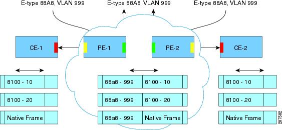
The S-bridge component is capable of inserting or removing a service provider VLAN (S-VLAN) for all traffic on a particular port. IEEE 802.1ad adds a new tag called a Service tag (S-tag) to all ingress frames traveling from the customer to the service provider.
The VLAN in the S-tag is used for forwarding the traffic in the service provider network. Different customers use different S-VLANs, which results in isolation of traffic of each customer. In the S-tag, provider bridges do not understand the standard Ethertype. Hence, they use an Ethertype value that is different from the standard 802.1Q Ethertype value. This difference makes customer traffic that is tagged with the standard Ethertype appear as untagged in the provider network. The customer traffic is tunneled in the port VLAN of the provider port. 802.1ad service provider user network interfaces (S-UNIs) and network-network interfaces (NNIs) implement the S-bridge component.
For example, a VLAN tag has a VLAN ID of 1, the C-tag Ethertype has a value of 8100 0001, the S-tag Ethertype has a value of 88A8 0001, and the class of service (CoS) has a value of zero.
C-tag S-tag
------------------------------------------------------- --------------------------------------------------
0x8100 | Priority bits | CFI | C-VLAN-ID 0x88A8 | Priority bits | 0 | S-VLAN-ID
------------------------------------------------------- --------------------------------------------------
All customer VLANs (C-VLANs) that enter a user network interface (UNI) port in an S-bridge component receive the same service (marked with the same S-VLAN). C-VLAN components are not supported, but a customer may want to tag a particular C-VLAN packet separately to differentiate between services. Provider bridges allow C-VLAN packet tagging with a provider edge bridge, called the C-bridge component of the provider bridge. C-bridge components are C-VLAN aware and can insert or remove a C-VLAN 802.1Q tag. The C-bridge UNI port is capable of identifying the customer 802.1Q tag and inserting or removing an S-tag on the packet on a per-service instance or C-VLAN basis. A C-VLAN tagged service instance allows service instance selection and identification by C-VLAN. The 801.1ad customer user network interfaces (C-UNIs) implement the C-component.
Dot1ad NNI port are core facing ports. On this port dot1ad (0x88A8) ethertype is used. The customer facing S-bridge port is identified by using the ethernet dot1ad nni command. The frames forwarded on this port are double tagged with the S-Tag ethertype set at. 0x88a8.
Layer 2 protocol data units (PDUs) of customers that are received by a provider bridge are not forwarded. Hence, Layer 2 protocols running at customer sites do not know the complete network topology. By using different set of addresses for the Layer 2 protocols running on provider bridges, IEEE 802.1ad causes Layer 2 PDUs of the customers device that enter the provider bridge to appear as unknown multicast traffic and forwards it on customer ports (on the same service provider VLAN (S-VLAN)). Layer 2 protocols of customer device can then run transparently.
The table below shows Layer 2 MAC addresses that are reserved for the C-VLAN component.
|
Assignment |
Value |
|---|---|
|
Bridge Group Address |
01-80-C2-00-00-00 |
|
IEEE 802.3 Full Duplex PAUSE Operation |
01-80-C2-00-00-01 |
|
IEEE 802.3 Slow_Protocols_Multicast_Address |
01-80-C2-00-00-02 |
|
IEEE 802.1X PAE Address |
01-80-C2-00-00-03 |
|
Provider Bridge Group Address |
01-80-C2-00-00-08 |
|
Provider Bridge GVRP Address |
01-80-C2-00-00-0D |
|
IEEE 802.1AB Link Layer Discovery Protocol Multicast Address |
01-80-C2-00-00-0E |
|
Reserved for future standardization |
01-80-C2-00-00-04 01-80-C2-00-00-05 01-80-C2-00-00-06 01-80-C2-00-00-07 01-80-C2-00-00-09 01-80-C2-00-00-0A 01-80-C2-00-00-0B 01-80-C2-00-00-0C 01-80-C2-00-00-0F |
The table below shows Layer 2 MAC addresses that are reserved for the S-VLAN component. These addresses are a subset of the C-VLAN component addresses, and the C-bridge does not forward the bridge protocol data units (BPDUs) of a provider to a customer network.
|
Assignment |
Value |
|---|---|
|
IEEE 802.3 Full Duplex PAUSE Operation |
01-80-C2-00-00-01 |
|
IEEE 802.3 Slow_Protocols_Multicast_Address |
01-80-C2-00-00-02 |
|
IEEE 802.1X PAE Address |
01-80-C2-00-00-03 |
|
Provider Bridge Group Address |
01-80-C2-00-00-08 |
|
Reserved for future standardization |
01-80-C2-00-00-04 01-80-C2-00-00-05 01-80-C2-00-00-06 01-80-C2-00-00-07 01-80-C2-00-00-09 01-80-C2-00-00-0A |
The table summarizes the actions when a packet is received with destination MAC address for C-UNI, S-UNI and NNI interfaces.
|
MAC Address |
Protocol |
C-UNI Action |
S-UNI Action |
NNI Action |
|---|---|---|---|---|
|
01-80-C2-00-00-00 |
Bridge Protocol Data Units (BPDUs) |
Peer |
Data |
Data |
|
01-80-C2-00-00-01 |
802.3X Pause Protocol |
Drop |
Drop |
Drop |
|
01-80-C2-00-00-02 |
Slow protocol address: 802.3ad LACP, 802.3ah OAM |
Peer |
Peer |
Peer |
|
01-80-C2-00-00-03 |
802.1x |
Not supported |
Not supported |
Not supported |
|
01-80-C2-00-00-04 |
Reserved for future media access method |
Drop |
Drop |
Drop |
|
01-80-C2-00-00-05 |
Reserved for future media access method |
Drop |
Drop |
Drop |
|
01-80-C2-00-00-06 |
Reserved for future bridge use |
Drop |
Drop |
Drop |
|
01-80-C2-00-00-07 |
Reserved for future bridge use |
Drop |
Drop |
Drop |
|
01-80-C2-00-00-08 |
Provider STP (BPDU) |
Drop |
Drop |
Peer |
|
01-80-C2-00-00-09 |
Reserved for future bridge use |
Drop |
Drop |
Drop |
|
01-80-C2-00-00-0A |
Reserved for future bridge use |
Drop |
Drop |
Drop |
|
01-80-C2-00-00-0B |
Reserved for future S-bridge use |
Drop |
Drop |
Drop |
|
01-80-C2-00-00-0C |
Reserved for future S-bridge purposes |
Drop |
Drop |
Drop |
|
01-80-C2-00-00-0D |
Provider bridge Generic VLAN Registration Protocol (GVRP) address |
Drop |
Drop |
Drop |
|
01-80-C2-00-00-0E |
802.1ab Link Layer Discovery Protocol (LLDP) |
may Peer |
Data |
Data |
|
01-80-C2-00-00-0F |
Reserved for future C- bridge or Q-bridge use |
Drop |
Drop |
Drop |
|
01-80-C2-00-00-10 |
All bridge domains |
Not supported |
Not supported |
Not supported |
|
01-80-C2-00-00-20 |
GARP Multicast Registration Protocol (GMRP) |
Data |
Data |
Data |
|
01-80-C2-00-00-21 |
Generic VLAN Registration Protocol (GVRP) |
Data |
Data |
Data |
|
01-80-C2-00-00-22-2F |
Other GARP addresses |
Data |
Data |
Data |
|
01-00-0C-CC-CC-CC |
Port Aggregation Protocol (PagP), UniDirectional Link Detection (UDLD), |
Peer |
Peer |
Peer |
| Cisco Discovery Protocol (CDP), VLAN Trunk Protocol (VTP) |
Peer |
Data |
Data |
|
| Dynamic Trunking Protocol (DTP) |
NA |
NA |
NA |
|
|
01-00-0C-CC-CC-CD |
Per-VLAN Spanning Tree (PVST) |
Peer |
Data |
Data |
Note |
|
| Command or Action | Purpose | |
|---|---|---|
| Step 1 |
enable Example: |
Enables privileged EXEC mode.
|
| Step 2 |
configure terminal Example: |
Enter global configuration mode. |
| Step 3 |
interface interface-id Example: |
Enter interface configuration mode. Valid interfaces are physical ports. |
| Step 4 |
ethernet dot1ad {nni | uni {c-port | s-port}} Example: |
Configures dot1ad NNI, C-port or S-port on the interface. |
| Step 5 |
service instance number ethernet [name] Example: |
Configure an EFP (service instance) and enter service instance configuration) mode.
|
| Step 6 |
encapsulation {default | dot1q | priority-tagged | untagged} Example: |
Configure encapsulation type for the service instance.
|
| Step 7 |
bridge-domain bridge-id [split-horizon group group-id] Example: |
Configure the bridge domain ID. The range is from 1 to 4000. You can use the split-horizon keyword to configure the port as a member of a split horizon group. The group-id range is from 0 to 2. |
| Step 8 |
rewrite ingress tag { pop {1 | 2} symmetric | push dot1ad vlan-id [dot1q vlan-id] symmetric} Example: |
(Optional) Specify that encapsulation modification to occur on packets at ingress.
|
| Step 9 |
end Example: |
Return to privileged EXEC mode. |
interface GigabitEthernet0/3/7
ethernet dot1ad uni c-port
service instance 20 ethernet
encapsulation dot1q 20
rewrite ingress tag push dot1ad 30 symmetric
bridge-domain 20
interface GigabitEthernet0/3/7
ethernet dot1ad uni s-port
service instance 20 ethernet
encapsulation default
rewrite ingress tag push dot1ad 30 symmetric
bridge-domain 20
interface GigabitEthernet0/5/2
ethernet dot1ad nni
service instance 20 ethernet
encapsulation dot1ad 30
bridge-domain 20
Note |
|
| Command or Action | Purpose | |||
|---|---|---|---|---|
| Step 1 |
enable Example: |
Enables privileged EXEC mode.
|
||
| Step 2 |
configure terminal Example: |
Enter global configuration mode. |
||
| Step 3 |
interface interface-id Example: |
Enter interface configuration mode. Valid interfaces are physical ports. |
||
| Step 4 |
ethernet dot1ad {nni | uni {c-port}} Example: |
Configures Trunk EFP on dot1ad NNI and C-UNI ports on the interface.
|
||
| Step 5 |
service instance [trunk] number ethernet Example: |
Configure an EFP (service instance) and enter service instance configuration) mode
|
||
| Step 6 |
encapsulation dot1q Example: |
Configure encapsulation type for the service instance.
|
||
| Step 7 |
bridge-domin bridge-id from-encapsulation Example: |
Configures the router to derive bridge domains from the encapsulation VLAN list. |
||
| Step 8 |
rewrite ingress tag { pop {1 | 2} symmetric Example: |
(Optional) Specify that encapsulation modification to occur on packets at ingress.
|
||
| Step 9 |
end Example: |
Return to privileged EXEC mode. |
interface GigabitEthernet0/3/7
ethernet dot1ad uni c-port
service instance trunk 20 ethernet
encapsulation dot1q 20-30
rewrite ingress tag pop1 symmetric
bridge-domain from-encapsulation
interface GigabitEthernet0/5/2
ethernet dot1ad nni
service instance trunk 20 ethernet
encapsulation dot1ad 20-30
rewrite ingress tag pop1 symmetric
bridge-domain from-encapsulation
Note |
|
| Command or Action | Purpose | |
|---|---|---|
| Step 1 |
enable Example: |
Enables privileged EXEC mode.
|
| Step 2 |
configure terminal Example: |
Enter global configuration mode. |
| Step 3 |
interface interface-id Example: |
Enter interface configuration mode. Valid interfaces are physical ports. |
| Step 4 |
ethernet dot1ad {nni | uni {c-port | s-port}} Example: |
Configures dot1ad NNI, C-port or S-port on the interface. |
| Step 5 |
service instance number ethernet [name] Example: |
Configure an EFP (service instance) and enter service instance configuration) mode.
|
| Step 6 |
encapsulation {default | dot1q | priority-tagged | untagged} Example: |
Configure encapsulation type for the service instance.
|
| Step 7 |
rewrite ingress tag push dot1ad vlan-id [dot1q vlan-id] symmetric} Example: |
(Optional) Specify that encapsulation modification to occur on packets at ingress.
|
| Step 8 |
xconnect peer-router-id vcid pw-class pw-class name Example: |
Bind the attachment circuit to a pseudowire virtual circuit (VC) and enter cross connect configuration mode. |
| Step 9 |
end Example: |
Return to privileged EXEC mode. |
interface GigabitEthernet0/3/7
ethernet dot1ad uni c-port
service instance 20 ethernet
encapsulation dot1q 20
rewrite ingress tag push dot1ad 30 symmetric
xconnect 2.2.2.2 20 encap mpls
interface GigabitEthernet0/3/7
ethernet dot1ad uni s-port
service instance 20 ethernet
encapsulation default
rewrite ingress tag push dot1ad 30 symmetric
xconnect 2.2.2.2 20 encap mpls
interface GigabitEthernet0/3/7
ethernet dot1ad nni
service instance 20 ethernet
encapsulation dot1ad 20
xconnect 2.2.2.2 20 encap mpls
Use the show ethernet do1ad commands to verify IEEE 802.1ad configuration.
show ethernet do1ad
This command displays 802.1ad configuration globally on the router. The following is a sample output from the command:
Router# show ethernet dot1ad

Interface: GigabitEthernet0/2/1
DOT1AD NNI Port
L2protocol pass

Interface: GigabitEthernet0/2/7
DOT1AD C-Bridge Port
L2protocol pass
show ethernet do1ad [inteface inteface-name]
This command displays interface dot1ad configuration The following is a sample output from the command:
Router# show ethernet do1ad interface gigabitethernet 0/2/1

Interface: GigabitEthernet0/2/1
DOT1AD NNI Port
L2protocol pass
 Feedback