Configuring 4-Port
C37.94 Interface Module
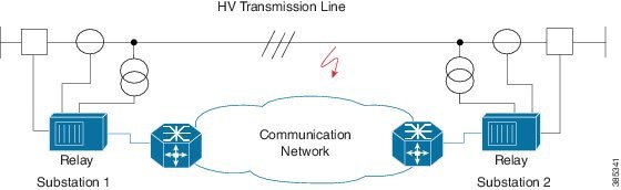
The IEEE C37.94 standard defines the communication of protection relays with communication equipment inside a substation using optical fibers.
The IEEE defines the C37.94 standard as N * 64 kbps optical fiber interface to provide transparent communications between tele-protection relays and multiplexers equipments. The C37.94 standard describes the interconnection details for the variable N, (where N = 1, 2…12), which describes a multiple of 64 kilobit per second connections at which the communication link is to operate.
The C37.94 interface module supports four ports from port number 0 to 3.
The 4-Port C37.94 interface module is supported on the RSP2 module of the Cisco ASR 902 and ASR 903 routers.
- Information About C37.94 Interface Module
- How to Configure C37.94 Interface Module
- Troubleshooting
- Additional References
Information About C37.94 Interface Module
This following section provides information about configuring C37.94 interface module on the Cisco ASR 903 Series Router.
- Smart Grid Tele-Protection Support
- Overview of C37.94 Frame
- Features of 4-Port C37.94 Interface Module
- Prerequisites
- Restrictions
- Benefits
Smart Grid Tele-Protection Support
The C37.94 interface module supports smart grid tele-protection.
Smart Grid refers to the electricity delivery system from the point of generation to the point of consumption using analog or digital information and the communication technology for gathering and acting on the information.
Tele-protection refers to the mechanism to quickly switch on alternative routes using tele-protection equipment when a malfunction occurs. The switchover is to improve the performance of the electric grid.
Overview of C37.94 Frame
The IEEE standard defines a data frame format for C37.94 interface module. The frame format is designed to allow the passage of information in packet format from the multiplexer to the tele-protection equipment and from the tele-protection equipment to the multiplexer equipment.
Features of 4-Port C37.94 Interface Module
The features of 4-Port C37.94 Interface Module are:
-
Supports 4 independent C37.94 interfaces
-
Provides low latency connection over pseudowires
-
Supports allocation of timeslot. Timeslot ranges from 1 to 12
-
Supports Online Insertion and Removal (OIR)
-
Supports traffic switch from active to standby
-
Provides quick switchover to alternative route at the time of a route failure
-
Populates the C37.94 controller indexes in IfTable; the IfTable is defined in IF-MIB
Prerequisites
Restrictions
-
The channelization of N * 64 kbps channels of C37.94 interface is not supported
-
The bandwidth of N * 64 kbps (N ranges from 1 to 12) is supported
-
Pseudowire configuration between local and remote PE with different time slots is not supported
-
Pseudowire configuration is supported only when C37.94 interface is configured on both PE nodes
-
C37.94 controller index in IfTable does not provide the following information:
Benefits
-
Provides low latency connection to C37.94 interfaces
-
Supports multiple interface modules on single chassis
-
Tele-protection relay checks a failure and thus provides reliable, robust and safe electric grid
-
Provides quick switchover to an alternative route of any route failure
-
Prevents damage to the network and power outages
How to Configure C37.94 Interface Module
- Configuring CEM Class
- Configuring CEM
- Verifying C37.94 Interface Module Configurations
- Associated Commands
Configuring CEM Class
Before you configure CEM class, configure payload size and dejitter buffer values on CEM.
enable
configure terminal
class cem mycemclass
payload-size 64
dejitter-buffer 20
idle-pattern 0x55
end
 Note |
Configuring CEM
Before you configure CEM group cross-connect, configure the C37.94 controller.
enable
configure terminal
controller c3794 0/0/0
cem-group 0 timeslots 12
exit
interface cem 0/0/0
no ip address
cem 0
cem class mycemclass
xconnect 10.10.10.10 200 encapsulation mpls
exit
Note | The controller is auto-configured when the interface module is inserted. |
Verifying C37.94 Interface Module Configurations
You use the following show commands to verify the configuration of 4-Port C37.94 interface module:
-
Use the show running-config command to view the configurations.
Router# show running-config | sec 0/0/0

controller C3794 0/0/0
  cem-group 0 timeslots 12
interface CEM0/0/0
no ip address
cem 0
  xconnect 10.10.10.10 200 encapsulation mpls
-
Use the show xconnect command to verify the configuration of cross connect between the controllers.
Router# show xconnect all

Legend:    XC ST=Xconnect State  S1=Segment1 State  S2=Segment2 State
  UP=Up       DN=Down            AD=Admin Down      IA=Inactive
  SB=Standby  HS=Hot Standby     RV=Recovering      NH=No Hardware

XC ST  Segment 1                         S1 Segment 2                         S2
------+---------------------------------+--+---------------------------------+--
UP pri   ac CE0/0/0:0(CESoPSN Basic)     UP mpls 10.10.10.10 200              UP
-
Use the show cem circuit command to verify the CEM configurations.
Router# show cem circuit detail

CEM0/0/0, ID: 0, Line: UP, Admin: UP, Ckt: ACTIVE
Controller state: up, T1/E1 state: up
Idle Pattern: 0xFF, Idle CAS: 0x8
Dejitter: 5 (In use: 0)
Payload Size: 96
Framing: Framed (DS0 channels: 1-12)
CEM Defects Set
None

Signalling: No CAS
RTP: No RTP

Ingress Pkts:    26669            Dropped:             0
Egress Pkts:     26669            Dropped:             0

CEM Counter Details
Input Errors:    0                    Output Errors:       0
Pkts Missing:    0                    Pkts Reordered:      0
Misorder Drops:  0                    JitterBuf Underrun:  0
Error Sec:       0                    Severly Errored Sec: 0
Unavailable Sec: 0                    Failure Counts:      0
Pkts Malformed:  0                    JitterBuf Overrun:   0
-
Use the show controllers command to verify the controller configurations.
Router# show controllers c3794 0/0/0

C3794 0/0/0 - (A900-IMA4C3794) is up
Configured Channels: 1
Peer Channels      : 1
Alarm                              : Nil
Sending Y-Alarm to Peer Device     : No
Receiving Y-Alarm from Peer Device : No
Transceiver Rx Optical Power :-15 db
Associated Commands
|
Commands |
URL |
|---|---|
|
cem-group |
|
|
xconnect |
|
|
loopback |
Troubleshooting
You use the following to troubleshoot C37.94 controllers:
Alarms
The 4-Port C37.94 interface module supports the following alarms during failure:
Loss of Signal
The scenario when the receiver end receives two or more errors in eight consecutive framing patterns within 1 millisecond, the Loss of Signal (LOS) alarm is declared.
The receiver end should clear LOS after receiving eight consecutive correct framing patterns.
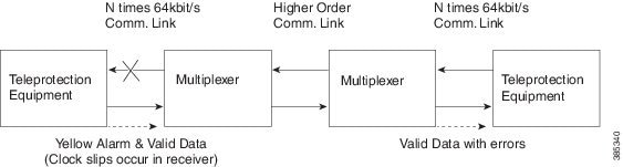
Failure Scenarios
-
During the LOS condition at its optical receive port
At Tele-protection Equipment
At Multiplexer Equipment
-
Replaces the data bits over the higher order communications link with “All Ones,” which is commonly referred to as Alarm Indication Signal (AIS).
-
Changes the “Yellow” bit in the transmitted optical output frames from “0” to “1”
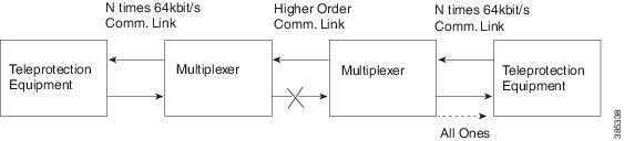
Figure 3. LOS at Optical Receive Port of Multiplexer 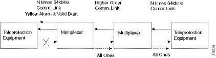
-
-
During the loss of the higher order communications link, the multiplexer should replace the data bits in the transmitted optical output frames with “All Ones.”
Path Yellow Detection
The scenario is declared as path yellow when three consecutive received frames have the “Yellow” bit = 1 and the received signal is OK (no LOS).
The receiver clears path yellow when three consecutive received frames have the “Yellow” bit = 0 or the received signal is bad (LOS).
Loopback on C37.94 Interfaces
Loopback Description
You can use the following loopbacks on the C37.94 interfaces.
|
Loopback |
Description |
|---|---|
|
loopback local line |
Loops the incoming signal in the interface using the framer’s line loopback mode. The framer does not reclock or reframe the incoming data. All incoming data is received by the interface driver. |
|
loopback local payload |
Loops the incoming signal back in the interface using the payload loopback mode of the framer. The framer reclocks and reframes the incoming data before sending it back out to the network. |
|
loopback network line |
Sets the loopback toward the network before going through the framer (line). |
|
loopback network payload |
Sets the loopback toward the network after going through the framer (payload). |
Configuring Loopback
Before You Begin
Before you configure loopback, you must configure the controller and the CEM.
enable
configure terminal
controller c3794 0/0/0
loopback local  line
exit
enable
configure terminal
controller c3794 0/0/0
loopback network  payload
exit
Note | To remove a loopback, use the no loopback command. |
Verifying the Loopback Configurations
You use the following show command to verify the loopback configuration of 4-Port C37.94 interface module:
Additional References
Related Documents
|
Related Topic |
Document Title |
|---|---|
|
Cisco IOS commands |
Standards and RFCs
|
Standard/RFC |
Title |
|---|---|
|
— |
There are no standards and RFCs for this feature. |
MIBs
|
MIB |
MIBs Link |
|---|---|
|
IF-MIB |
To locate and download MIBs for selected platforms, Cisco IOS releases, and feature sets, use Cisco MIB Locator found at the following URL: |
Technical Assistance
|
Description |
Link |
|---|---|
|
The Cisco Support website provides extensive online resources, including documentation and tools for troubleshooting and resolving technical issues with Cisco products and technologies. To receive security and technical information about your products, you can subscribe to various services, such as the Product Alert Tool (accessed from Field Notices), the Cisco Technical Services Newsletter, and Really Simple Syndication (RSS) Feeds. Access to most tools on the Cisco Support website requires a Cisco.com user ID and password. |
 Feedback