E and M Signals over
MPLS
This chapter provides information about peer-to-peer transport of rEceive and transMit (E and M) signals and voice data over MPLS on the Cisco ASR 903 Router.
- E and M Signaling Overview
- Restrictions
- Information About Voice Port Configuration
- How to Configure Analog Voice Ports
- Configuration Examples for E and M
- Verifying E & M Configuration
- Additional References for Configuring E and M Signals
E and M Signaling Overview
E and M signaling defines a trunk circuit side and a signaling unit side for each connection similar to the data circuit-terminating equipment (DCE) and data terminal equipment (DTE) reference type. The analog E and M interface functions as the signaling unit side and it expects the other side to be a trunk circuit.
 Note | E and M controller indexes are populated in IfTable, the IfTable is defined in IF-MIB. |
Restrictions
Information About Voice Port Configuration
The following section provides an overview of voice port configuration.
- Voice Port Configuration Overview
- Telephony Signaling Interfaces
- Codec Complexity for Analog Voice Ports
- Circuit Emulation Service Overview
- CAS Overview
Voice Port Configuration Overview
Voice ports are found at the intersections of packet-based networks and traditional telephony networks, and they facilitate the passing of voice and call signals between the two networks. Physically, voice ports connect a router or access server to a line from a circuit-switched telephony device in a PBX or the PSTN.
Basic software configuration for voice ports describes the type of connection being made and the type of signaling to take place over this connection. In addition to the commands for basic configuration, there are also commands that provide fine-tuning for voice quality, enable special features, and specify parameters to match those of proprietary PBXs.
Voice ports on routers and access servers emulate physical telephony switch connections so that voice calls and their associated signaling can be transferred intact between a packet network and a circuit-switched network or device. For a voice call to occur, certain information must be passed between the telephony devices at either end of the call. This information is referred to as signaling. The devices at both ends of the call segment must use the same type of signaling.
The devices in the packet network must be configured to convey signaling information in a way that the circuit-switched network can understand. The devices must also be able to understand signaling information received from the circuit-switched network.
Telephony Signaling Interfaces
Voice ports on routers and access servers physically connect the router or access server to telephony devices such as telephones, fax machines, PBXs, and PSTN central office (CO) switches. These devices may use any of several types of signaling interfaces to generate information about on-hook status, ringing, and line seizure.
The router’s voice-port hardware and software need to be configured to transmit and receive the same type of signaling being used by the device with which they are interfacing so that calls can be exchanged smoothly between the packet network and the circuit-switched network.
The signaling interface discussed in this document is receive and transmit (E&M), which is the type of analog interface. Some digital connections emulate E&M interfaces. It is important to know which signaling method the telephony side of the connection is using, and to match the router configuration and voice interface hardware to that signaling method.
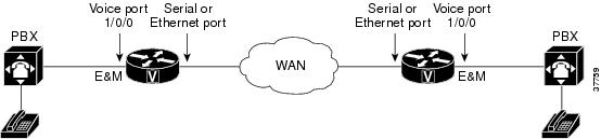
In the following example, two PBXs are connected across a WAN by E&M interfaces. This illustrates the path over a WAN between two geographically separated offices in the same company.
E and M Interfaces
Trunk circuits connect telephone switches to one another; they do not connect end-user equipment to the network. The most common form of analog trunk circuit is the E&M interface, which uses special signaling paths that are separate from the trunk’s audio path to convey information about the calls. The signaling paths are known as the E-lead and the M-lead. The name E&M is thought to derive from the phrase Ear and Mouth or rEceive and transMit although it could also come from Earth and Magnet. The history of these names dates back to the days of telegraphy, when the CO side had a key that grounded the E circuit, and the other side had a sounder with an electromagnet attached to a battery. Descriptions such as Ear and Mouth were adopted to help field personnel determine the direction of a signal in a wire. E&M connections from routers to telephone switches or to PBXs are preferable to FXS/FXO connections because E&M provides better answer and disconnect supervision.
Like a serial port, an E&M interface has a data terminal equipment/data communications equipment (DTE/DCE) type of reference. In telecommunications, the trunking side is similar to the DCE, and is usually associated with CO functionality. The router acts as this side of the interface. The other side is referred to as the signaling side, like a DTE, and is usually a device such as a PBX. Five distinct physical configurations for the signaling part of the interface (Types I-V) use different methods to signal on-hook/off-hook status, as shown in the table below. Cisco voice implementation supports E&M Types I, II, III, and V.
|
E&M Type |
E-Lead Configuration |
M-Lead Configuration |
Signal Battery Lead Configuration |
Signal Ground Lead Configuration |
|---|---|---|---|---|
|
I |
Output, relay to ground |
Input, referenced to ground |
-- |
-- |
|
II |
Output, relay to SG |
Input, referenced to ground |
Feed for M, connected to -48V |
Return for E, galvanically isolated from ground |
|
III |
Output, relay to ground |
Input, referenced to ground |
Connected to -48V |
Connected to ground |
|
V |
Output, relay to ground |
Input, referenced to -48V |
-- |
-- |
The physical E&M interface is an RJ-48 connector that connects to PBX trunk lines, which are classified as either two-wire or four-wire. This refers to whether the audio path is full duplex on one pair of wires (two-wire) or on two pair of wires (four-wire). A connection may be called a four-wire E&M circuit although it actually has six to eight physical wires. It is an analog connection although an analog E&M circuit may be emulated on a digital line.
PBXs built by different manufacturers can indicate on-hook/off-hook status and telephone line seizure on the E&M interface by using any of the following three types of access signaling:
-
Immediate-start is the simplest method of E&M access signaling. The calling side seizes the line by going off-hook on its E-lead and sends address information as dual-tone multifrequency (DTMF) digits following a short, fixed-length pause.
-
Wink-start is the most commonly used method for E&M access signaling, and is the default for E&M voice ports. Wink-start was developed to minimize glare, a condition found in immediate-start E&M, in which both ends attempt to seize a trunk at the same time. In wink-start, the calling side seizes the line by going off-hook on its E-lead, then waits for a short temporary off-hook pulse, or "wink," from the other end on its M-lead before sending address information. The switch interprets the pulse as an indication to proceed and then sends the dialed digits as DTMF or dialed pulses.
-
In delay-dial signaling, the calling station seizes the line by going off-hook on its E-lead. After a timed interval, the calling side looks at the status of the called side. If the called side is on-hook, the calling side starts sending information as DTMF digits; otherwise, the calling side waits until the called side goes on-hook and then starts sending address information.
E and M Interface Transmission Only
In Transmission Only (TO) mode configuration, CESoP is configured without CAS support to transport voice data using T1/E1CESoP PW. Field Programmable Gate Arrays (FPGA) configures the port to Transmission Only and port is always on off-hook mode.
In this mode, signaling is not expected to provide through router.
E and M Signaling
Start dial supervision is the line protocol that defines how the equipment seizes the E&M trunk and passes the address signaling information such as dual tone multifrequency (DTMF) digits. There are three main techniques used for E&M start dial signaling:
-
Immediate Start-This is the most basic protocol. In this technique, the originating switch goes off-hook, waits for a finite period of time (for example, 200 ms), then sends the dial digits to the far end.
-
Wink Start—Wink is the most commonly used protocol. In this technique, the originating switch goes off-hook, waits for a temporary off-hook pulse from the other end (which is interpreted as an indication to proceed), then sends the dial digits.
-
Delay Dial—In this technique, the originating side goes off-hook and waits for about 200 ms, then checks to see if the far end is on-hook. If the far end is on-hook, it then outputs dial digits. If the far end is off-hook, it waits until it goes on-hook, then outputs dial digits.
Codec Complexity for Analog Voice Ports
The term codec stands for coder-decoder. A codec is a particular method of transforming analog voice into a digital bit stream (and vice versa) and also refers to the type of compression used. Several different codecs have been developed to perform these functions, and each one is known by the number of the International Telecommunication Union-Telecommunication Standardization Sector (ITU-T) standard in which it is defined. The various codecs use different algorithms to encode analog voice into digital bit-streams and have different bit rates, frame sizes, and coding delays associated with them. The codecs also differ in the type of perceived voice quality they achieve.
Select the same type of codec as the one that is used at the other end of the call. For instance, if a call was coded with a G.711 codec, it must be decoded with a G.711 codec.
Circuit Emulation Service Overview
Circuit Emulation (CEM) is a technology that provides a protocol-independent transport over IP Networks. It enables proprietary or legacy applications to be carried transparently to the destination, similar to a leased line.
The Cisco ASR 903 Series Router E & M IM supports pseudowire types that utilize CEM transport, Circuit Emulation Service over Packet-Switched Network in T1 and E1 modes to transport Analog Signals and Voice traffic over MPLS.
The voice port interfaces that connect the router or access server to E & M lines pass voice data and signaling between the packet network and the Analog-circuit-switched network.
For more information about the Circuit Emulation Service over Packet-Switched Network on Cisco ASR 903 Series Router, see Chapter 16 Configuring Pseudowire.
CAS Overview
Channel Associated Signaling (CAS) is also referred to as Robbed Bit Signaling. In this type of signaling, the least significant bit of information in a T1 signal is "robbed" from the channels that carry voice and is used to transmit framing and clocking information. This is sometimes called "in-band" signaling. CAS is a method of signaling each traffic channel rather than having a dedicated signaling channel (like ISDN). In other words, the signaling for a particular traffic circuit is permanently associated with that circuit. The most common forms of CAS signaling are loopstart, groundstart, Equal Access North American (EANA), and E&M. In addition to receiving and placing calls, CAS signaling also processes the receipt of Dialed Number Identification Service (DNIS) and automatic number identification (ANI) information, which is used to support authentication and other functions.
Each T1 channel carries a sequence of frames. These frames consist of 192 bits and an additional bit designated as the framing bit, for a total of 193 bits per frame. Super Frame (SF) groups twelve of these 193 bit frames together and designates the framing bits of the even numbered frames as signaling bits. CAS looks specifically at every sixth frame for the timeslot's or channel's associated signaling information. These bits are commonly referred to as A- and B-bits. Extended super frame (ESF), due to grouping the frames in sets of twenty-four, has four signaling bits per channel or timeslot. These occur in frames 6, 12, 18, and 24 and are called the A-, B-, C-, and D-bits respectively.
The biggest disadvantage of CAS signaling is its use of user bandwidth in order to perform signaling functions.
How to Configure Analog Voice Ports
- Configuring CEM Group and Parameters on Analog E and M Voice Ports
- Configuring CEM Group with Cross Connect
Configuring CEM Group and Parameters on Analog E and M Voice Ports
Perform this task to configure cem group and basic parameters:
1.
enable
2.
configure
terminal
3.
controller
voice-port
slot
/
subslot
/
port
4.
cem-group
group-number
timeslots
timeslot
5.
compand-type
a-law
|
u-law
6.
signal
wink-start
|
immediate-start
|
delay-dial
7.
type
1 |
2 |
3 |
5 |TO
8.
operation
2-wire
|
4-wire
9.
impedance
600r
|
complex1
|
complex2
|
complex3
10.
exit
DETAILED STEPS
Configuring CEM Group with Cross Connect
The following section describes how to configure a CEM group on the Cisco ASR 903 Series Router.
1.
enable
2.
configure
terminal
3.
interface
cem
slot/bay
/port
4.
cem
number
5.
xconnect
router-id
vcid
encapsulation
mpls
6.
exit
DETAILED STEPS
| Command or Action | Purpose | |
|---|---|---|
| Step 1 |
enable
Example: Router> enable |
Enables privileged EXEC mode. |
| Step 2 |
configure
terminal
Example: Router# configure terminal |
Enters global configuration mode. |
| Step 3 |
interface
cem
slot/bay
/port
Example: Router(config)# int cem slot/bay/port |
To specify the slot number, bay number or port number to be configured. |
| Step 4 |
cem
number
Example: Router(config-if)# cem 0 |
CEM number is always 0. |
| Step 5 | xconnect
router-id
vcid
encapsulation
mpls
Example: Router(config-if)# xconnect 1.1.1.1 40 encapsulation mpls |
To configure xconnect with other end using router-ID, VCID and encapsulation as MPLS. |
| Step 6 |
exit
Example: Router(config-if)# exit |
Exits configuration mode and returns to privileged EXEC mode. |
Configuration Examples for E and M
Example: Configuring E&M Controller
This section provides examples for configuring E&M over MPLS
The following example shows how to configure voice port interface.
Router> enable
Router# configure terminal
Router(config)# controller voice-port 0/1/4
Router(config-controller)# cem-group 0 timeslots 1
Router(config-controller)# compand a-law
Router(config-controller)# signal immediate
Router(config-controller)# type 5
Router(config-controller)# operation 4-wire
Router(config-controller)# exit
Example: Configuring Xconnect
The following example shows how to configure xconnect.
Router> enable
Router# configure terminal
Router(config)# interface CEM0/1/0
Router(config-if)# cem 0
Router(config-if-cem)# xconnect 1.1.1.1 1 encapsulation mpls
Router(config-if-cem-xconn)# end
Verifying E & M Configuration
The following show commands you can use to verify the E and M configuration.
- show controllers voice-port: This command shows
how to configure voice port interface.
Router# show controllers voice-port 0/3/0

	voice-port 0/3/0 - (A900-IMA6EM) is up
 Encapsulation : None
 Type          : Type I
 Operation     : 2-Wire
 Signalling    : wink-start
 Companding    : u-law
- show interface cem: This command shows how to
configure CEM.
Router# show interface CEM0/3/0 CEM0/3/0 is up, line protocol is up Hardware is Circuit Emulation Interface MTU 1500 bytes, BW 64 Kbit/sec, DLY 0 usec, reliability 255/255, txload 1/255, rxload 1/255 Encapsulation CEM, loopback not set Keepalive not supported Last input never, output never, output hang never Last clearing of "show interface" counters never Input queue: 0/375/0/0 (size/max/drops/flushes); Total output drops: 0 Queueing strategy: fifo Output queue: 0/0 (size/max) 5 minute input rate 0 bits/sec, 0 packets/sec 5 minute output rate 0 bits/sec, 0 packets/sec 0 packets input, 0 bytes, 0 no buffer Received 0 broadcasts (0 IP multicasts) 0 runts, 0 giants, 0 throttles 0 input errors, 0 CRC, 0 frame, 0 overrun, 0 ignored, 0 abort 0 packets output, 0 bytes, 0 underruns 0 output errors, 0 collisions, 0 interface resets 0 unknown protocol drops 0 output buffer failures, 0 output buffers swapped out - show cem circuit: This command shows how to
configure CEM circuit.
Router# show cem circuit 0

CEM0/3/0, ID: 0, Line: UP, Admin: UP, Ckt: ACTIVE
Controller state: up, T1/E1 state: up
Idle Pattern: 0xFF, Idle CAS: 0x8
Dejitter: 8 (In use: 0)
Payload Size: 32
Framing: Framed (DS0 channels: 1)
CEM Defects Set
None

Signalling: No CAS
RTP: No RTP

Ingress Pkts:    0                    Dropped:             0
Egress Pkts:     0                    Dropped:             0

CEM Counter Details
Input Errors:    0                    Output Errors:       0
Pkts Missing:    0                    Pkts Reordered:      0
Misorder Drops:  0                    JitterBuf Underrun:  0
Error Sec:       0                    Severly Errored Sec: 0
Unavailable Sec: 0                    Failure Counts:      0
Pkts Malformed:  0                    JitterBuf Overrun:   0
- show xconnect all: This command shows the output
of xconnect command.
Router# show xconnect all

Legend:    XC ST=Xconnect State  S1=Segment1 State  S2=Segment2 State
  UP=Up       DN=Down            AD=Admin Down      IA=Inactive
  SB=Standby  HS=Hot Standby     RV=Recovering      NH=No Hardware

XC ST  Segment 1                         S1 Segment 2                         S2
------+---------------------------------+--+---------------------------------+--
UP pri   ac CE0/3/0:0(CESoPSN Basic)     UP mpls 1.1.1.1:1                    UP
UP pri   ac CE0/3/1:0(CESoPSN Basic)     UP mpls 1.1.1.1:2                    UP
UP pri   ac CE0/3/2:0(CESoPSN Basic)     UP mpls 1.1.1.1:3                    UP
UP pri   ac CE0/3/3:0(CESoPSN Basic)     UP mpls 1.1.1.1:4                    UP
UP pri   ac CE0/3/4:0(CESoPSN Basic)     UP mpls 1.1.1.1:5                    UP
UP pri   ac CE0/3/5:0(CESoPSN Basic)     UP mpls 1.1.1.1:6                    UP
- show ip int brief: This command shows the
usability status of interfaces configured for IP.
Router# show ip int brief
Interface              IP-Address      OK? Method Status                Protocol
GigabitEthernet0/4/0   123.123.123.2   YES NVRAM  up                    up
GigabitEthernet0       7.19.15.129     YES NVRAM  up                    up
CEM0/3/0               unassigned      YES unset  up                    up
CEM0/3/1               unassigned      YES unset  up                    up
CEM0/3/2               unassigned      YES unset  up                    up
CEM0/3/3               unassigned      YES unset  up                    up
CEM0/3/4               unassigned      YES unset  up                    up
CEM0/3/5               unassigned      YES unset  up                    up
Additional References for Configuring E and M Signals
Related Documents
|
Related Topic |
Document Title |
|---|---|
|
Cisco IOS commands |
Standards and RFCs
|
Standard/RFC |
Title |
|---|---|
|
— |
There are no standards and RFCs for this feature. |
MIBs
|
MIB |
MIBs Link |
|---|---|
|
IF-MIB |
To locate and download MIBs for selected platforms, Cisco IOS releases, and feature sets, use Cisco MIB Locator found at the following URL: |
Technical Assistance
|
Description |
Link |
|---|---|
|
The Cisco Support website provides extensive online resources, including documentation and tools for troubleshooting and resolving technical issues with Cisco products and technologies. To receive security and technical information about your products, you can subscribe to various services, such as the Product Alert Tool (accessed from Field Notices), the Cisco Technical Services Newsletter, and Really Simple Syndication (RSS) Feeds. Access to most tools on the Cisco Support website requires a Cisco.com user ID and password. |
 Feedback