-
null
Cisco Double-Wide High Density Analog
Service Modules
This chapter provides information about the following Double-Wide High Denstiy Analog Service Module (DWSM).
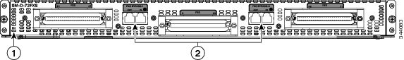
1. ![]() Cisco SM-D-72FXS Service Module—A 72 FXS port DWSM with 4 out of the 72 ports supporting OPX `Lite' capabilities.
Cisco SM-D-72FXS Service Module—A 72 FXS port DWSM with 4 out of the 72 ports supporting OPX `Lite' capabilities.
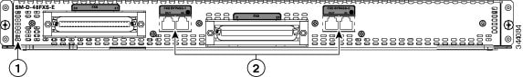
2. ![]() Cisco SM-D-48FXS-E Service Module—A 48 FXS port DWSM with all 48 ports supporting OPX Lite capabilities.
Cisco SM-D-48FXS-E Service Module—A 48 FXS port DWSM with all 48 ports supporting OPX Lite capabilities.

Note ![]() DWSM refers to both the Cisco SM-D-72FXS and SM-D-48FXS-E Service Module.
DWSM refers to both the Cisco SM-D-72FXS and SM-D-48FXS-E Service Module.
This chapter contains the following sections:
•![]() Double-Wide High Density Analog Service Module Overview
Double-Wide High Density Analog Service Module Overview
•![]() Cisco SM-D-72FXS Service Module Specifications
Cisco SM-D-72FXS Service Module Specifications
•![]() Cisco SM-D-48FXS-E Service Module Specifications
Cisco SM-D-48FXS-E Service Module Specifications
•![]() Connecting to the Double-Wide High Density Service Module Ports
Connecting to the Double-Wide High Density Service Module Ports
Double-Wide High Density Analog Service Module Overview
The Double-Wide High Density Service Module (DWSM) is supported on the following platforms:
•![]() Cisco 3945
Cisco 3945
•![]() Cisco 3945e
Cisco 3945e
•![]() Cisco 3925
Cisco 3925
•![]() Cisco 3925e
Cisco 3925e
•![]() Cisco 2951
Cisco 2951
The modules can be plugged in the following DWSM slots of the following platforms:
•![]() On Cisco 3945 and Cisco 3945e - only on slot 4.
On Cisco 3945 and Cisco 3945e - only on slot 4.
•![]() On Cisco 3925, Cisc0 3925e and Cisco 2951 - only on slot 2.
On Cisco 3925, Cisc0 3925e and Cisco 2951 - only on slot 2.
Table 2-1 shows the comparison between Cisco SM-D-72FXS and SM-D-48FXS-E.
Table 2-1 Feature comparison of SM-D-72FXS and SM-D-48FXS-E
|
|
|
|
|---|---|---|
Number of FXS Ports |
72 (Port 0 to Port 71) |
48 (Port 0 to Port 47) |
Number of Ports Configurable as FXS-E |
4 (Port 0 to Port 3) |
48 (all ports) |
Max RENs/Port |
5 REN/FXS Port 2 REN/FXS-E Port |
5 REN/FXS Port 2 REN/FXS-E Port |
Total REN Per DWSM Module |
40 |
30 |
RJ-21 Connectors |
3 |
2 |
FXO Bypass Ports1 |
2 (FXO Bypass Port 0: PSTN to Port 46) FXO Bypass Port 1: PSTN to Port 47) |
2 (FXO Bypass Port 0: PSTN to Port 46) FXO Bypass Port 1: PSTN to Port 47) |
1 Each FXO Bypass Port are made up of two RJ-11 connectors for PSTN In and Out. |
Installing SM-D-72FXS
Install the SM-D-72FXS according to the instructions in the Installing Cisco Interface Cards in Cisco Access Routers document.
Grounding
Ensure that the equipment you are working with is properly grounded according to the instructions in the Installing Cisco Interface Cards in Cisco Access Routers document.
Cables
The VG350 Voice Gateway uses RJ-21 cables to connect to a distribution box.

Connecting SM-D-72FXS
To connect the SM-D-72FXS, follow the these steps:
Step 1 ![]() Confirm that the router is turned off.
Confirm that the router is turned off.
Step 2 ![]() Connect one end of the straight-through RJ-21 cable to an RJ-21 distribution box.
Connect one end of the straight-through RJ-21 cable to an RJ-21 distribution box.
Step 3 ![]() Connect the distribution box ports to a telephone or FAX machine using RJ-11 cable.
Connect the distribution box ports to a telephone or FAX machine using RJ-11 cable.
Step 4 ![]() Power up the router.
Power up the router.
Installing SM-D-48FXS-E
Install the SM-D-72FXS according to the instructions in the Installing Cisco Interface Cards in Cisco Access Routers document.
Grounding
Ensure that the equipment you are working with is properly grounded according to the instructions in the Installing Cisco Interface Cards in Cisco Access Routers document.
Cables
The VG350 Voice Gateway uses RJ-21 cables to connect to a distribution box.
Connecting SM-D-48FXS-E
To connect the SM-D-48FXS-E, follow the these steps:
Step 1 ![]() Confirm that the router is turned off.
Confirm that the router is turned off.
Step 2 ![]() Connect one end of the straight-through RJ-21 cable to an RJ-21 distribution box.
Connect one end of the straight-through RJ-21 cable to an RJ-21 distribution box.
Step 3 ![]() Connect the distribution box ports to a telephone or FAX machine using an RJ-11 cable.
Connect the distribution box ports to a telephone or FAX machine using an RJ-11 cable.
Step 4 ![]() Power up the router.
Power up the router.
FXO Fail-Over Bypass Ports
Bypass/Failover Port, also called Fail-over Trunk Bypass, provides a way to use designated analog phone ports to make phone calls through the Public Switch Telephone Network (PSTN) during power-outage or power savings circumstances.
Table 2-2 shows the RJ-11 connector assignment.
Table 2-2 RJ-11 Connector Assignment
Cisco SM-D-72FXS Service Module Specifications
Physical Description and LEDs
All interface ports and LEDs are on the rear of the chassis. Figure 2-1 illustrates their locations.
Figure 2-1 Cisco SM-D-72FXS Service Module LEDs
|
|
EN LED |
|
FXO Bypass ports |
Cisco SM-D-48FXS-E Service Module Specifications
Physical Description and LEDs
All interface ports and LEDs are on the rear of the chassis. Figure 2-2 illustrates their locations.
Figure 2-2 Cisco SM-D-48FXS-E Service Module LEDs
|
|
EN LED |
|
FXO Bypass ports |
Port Numbering Conventions
Port numbering conventions for the Cisco VG350 Voice Gateway are as follows:
•![]() Two Compact Flash slots, CF0 and CF1.
Two Compact Flash slots, CF0 and CF1.
•![]() GE ports are 10/100/1000 BASE-T, numbered GE 0/0 through GE 0/2.
GE ports are 10/100/1000 BASE-T, numbered GE 0/0 through GE 0/2.
•![]() 10/100BASE-T ports are numbered 10/100BASE-T 0/0 and 10/100BASE-T 0/1 from right to left.
10/100BASE-T ports are numbered 10/100BASE-T 0/0 and 10/100BASE-T 0/1 from right to left.
•![]() FXS voice port numbering begins at 2/0/0 to 2/0/71 or 2/0/47 and 4/0/0 to 4/0/71 or 4/0/47, depending on the number of voice ports.
FXS voice port numbering begins at 2/0/0 to 2/0/71 or 2/0/47 and 4/0/0 to 4/0/71 or 4/0/47, depending on the number of voice ports.
The ports numbered 2/0/x are for the SM installed in slot 1 and the ports numbered 4/0/x are for the Service Module (SM) installed in slot 2.
Connecting to the Double-Wide High Density Service Module Ports
Three RJ-21 female connectors are available on the SM-D-72FXS service module. The middle RJ-21 connector accesses FXS ports 0 to 23, the left RJ-21 female connector accesses ports 24 to 4, and the right RJ-21 connector accesses ports 48 to 71. Use RJ-21 male connector to connect from the DWSM RJ-21 ports to an FXS port RJ-11 distribution box.
Note ![]() Use an RJ-21 cable with Amphenol 50-pin connectors.
Use an RJ-21 cable with Amphenol 50-pin connectors.
Online Insertion and Removal
The DWSM can be hot-inserted into the VG350 Voice Gateway without any potential of electrical damage either to the SM or the Host because the Online Insertion and Removal (OIR) logic is present on all SM designs.
OIRl is the ability to insert and remove an SM while the system is running without causing electrical damage to the SM or Host and without interfering with the operation of any other modules or portions of a running system.
The basic feature for OIR support on an SM is the control and isolation of the 12V power rail via a field-effect transistor (FET). This FET is enabled in a controlled fashion after the SM card is fully inserted.
Insertion and Removal Steps
This section describes the sequence of steps when inserting or removing a DWSM. OIR can only be done on one service module at a time. It only supports the same service module type. If you remove an SM-D-72FXS, only another SM-D-72FXS can be inserted.
Insertion
The following steps show how to insert a service module.
1. ![]() Insert the service module into the slot.
Insert the service module into the slot.
2. ![]() Make sure that the following message is displayed:
Make sure that the following message is displayed:
*Apr 19 00:14:19.177: %LINK-3-UPDOWN: Interface Foreign Exchange Station x/y/z,
changed state to up
Note ![]() There are about 72 or 48 messages being displayed so it may take some time for the message to appear. Estimated waiting time is approximately 2 minutes.
There are about 72 or 48 messages being displayed so it may take some time for the message to appear. Estimated waiting time is approximately 2 minutes.
3. ![]() Use the following command to verify the voice ports after insertion.
Use the following command to verify the voice ports after insertion.
show voice port summary
Removal
The following steps show how to remove a service module.
1. ![]() Ensure there is no active call on the service module that you want to remove.
Ensure there is no active call on the service module that you want to remove.
Use the following command to find any active call in the system:
show voice call status
2. ![]() Use the following command to proceed:
Use the following command to proceed:
hw-module sm x oir-stop
where x is the slot number of the Service Module
3. ![]() Wait until the following message is displayed:
Wait until the following message is displayed:
SM Hardware slot 2 can be removed
4. ![]() Remove the service module from its slot.
Remove the service module from its slot.
EN LED
Each Service Module(SM) has an Enable LED that is mounted on the SM and visible through the faceplate of the SM. The EN LED includes:
•![]() Green / Amber Dual Color LED
Green / Amber Dual Color LED
•![]() Defaults to OFF / ON power up
Defaults to OFF / ON power up
 Feedback