Console and Auxiliary Port Signals and Pinouts
Cisco VG310 and Cisco VG320 come with the cable and adapters you need to connect a PC, an ASCII terminal, or a modem to your Cisco VG310 or Cisco VG320.
The cable kit includes:
-
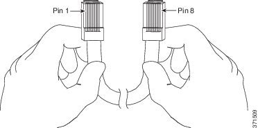
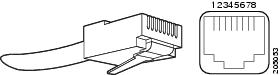
RJ-45-to-RJ-45 rollover cable
-
RJ-45-to-DB-9 adapter cable for console connection
-
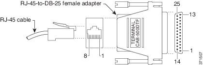
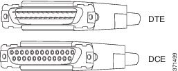
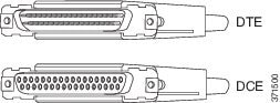
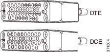
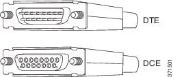
DB-9-to-DB-25 adapter cable for modem connection
The console port is configured as data communications equipment (DCE), and the auxiliary port is configured as data terminal equipment (DTE). Both are asynchronous serial ports and use RJ-45 connectors.


 Feedback