- Safety Recommendations
- Site Log
- Keeping Track-Checklist
- Mounting Tools and Equipment
- Unpacking and Inspection
- Rack-Mounting the Chassis
- Wall-Mounting the Chassis
- Bench-Top Installation
- Installing the Ground Connection
- Connecting Cables
Installing the Cisco VG224 Voice Gateway
This chapter contains the procedures for installing your Cisco VG224 voice gateway and consists of the following sections:
•![]() Installing the Ground Connection
Installing the Ground Connection
•![]() Ports, Connectors, and Pinouts
Ports, Connectors, and Pinouts
•![]() Remote Terminal Connections (If Applicable)
Remote Terminal Connections (If Applicable)

Tip ![]() While you do this installation, record your progress and site information. See the suggested format in the "Keeping Track-Checklist" section.
While you do this installation, record your progress and site information. See the suggested format in the "Keeping Track-Checklist" section.
 |
Warning |
|
Warning |
Safety Recommendations
The following information is included to alert you to safety recommendations and best practices when working with this equipment.
Maintaining Safety with Electricity
Follow these guidelines when working on equipment powered by electricity.
|
Warning |
General Safety Practices
Follow these guidelines to ensure personal safety and protect the equipment:
•![]() Keep the chassis area clear and dust-free during and after installation.
Keep the chassis area clear and dust-free during and after installation.
•![]() Put the removed chassis cover in a safe place.
Put the removed chassis cover in a safe place.
•![]() Keep tools away from walk areas where you and others could fall over them.
Keep tools away from walk areas where you and others could fall over them.
•![]() Do not wear loose clothing that could get caught in the chassis.
Do not wear loose clothing that could get caught in the chassis.
•![]() Wear safety glasses if you are working under any conditions that might be hazardous to your eyes.
Wear safety glasses if you are working under any conditions that might be hazardous to your eyes.
Safety Tips
Use these tips as safety guidelines when installing or working around this equipment.
•![]() Locate the emergency power-off switch for the room in which you are working. Then, if an electrical accident occurs, you can act quickly to turn off the power.
Locate the emergency power-off switch for the room in which you are working. Then, if an electrical accident occurs, you can act quickly to turn off the power.
•![]() Disconnect all power before installing or removing a chassis.
Disconnect all power before installing or removing a chassis.
•![]() Do not work alone if potentially hazardous conditions exist.
Do not work alone if potentially hazardous conditions exist.
•![]() Never assume that power is disconnected from a circuit. Always check.
Never assume that power is disconnected from a circuit. Always check.
•![]() Look carefully for possible hazards in your work area, such as moist floors, ungrounded power extension cables, and missing safety grounds.
Look carefully for possible hazards in your work area, such as moist floors, ungrounded power extension cables, and missing safety grounds.
•![]() If an electrical accident occurs, proceed as follows:
If an electrical accident occurs, proceed as follows:
–![]() Use caution; do not become a victim yourself.
Use caution; do not become a victim yourself.
–![]() Turn off power to the system.
Turn off power to the system.
–![]() If possible, send another person to get medical aid. Otherwise, assess the condition of the victim and then call for help.
If possible, send another person to get medical aid. Otherwise, assess the condition of the victim and then call for help.
–![]() Determine if the person needs rescue breathing or external cardiac compressions; then take appropriate action.
Determine if the person needs rescue breathing or external cardiac compressions; then take appropriate action.
Preventing Electrostatic Discharge Damage
Electrostatic discharge (ESD) can damage equipment and impair electrical circuitry. ESD occurs when electronic components are improperly handled; it can result in complete or intermittent failures.
Always follow ESD-prevention procedures when removing and replacing components.
•![]() Ensure that the chassis is electrically connected to earth ground.
Ensure that the chassis is electrically connected to earth ground.
•![]() Wear an ESD-preventive wrist strap, ensuring that it makes good skin contact.
Wear an ESD-preventive wrist strap, ensuring that it makes good skin contact.
•![]() Connect the clip to the ESD-strap connection jack (to the left of the power switch on the rear of the chassis) or to an unpainted chassis frame surface.
Connect the clip to the ESD-strap connection jack (to the left of the power switch on the rear of the chassis) or to an unpainted chassis frame surface.

Site Log
We recommend that you maintain a Site Log to record all actions relevant to the system. Site Log entries might include the following:
•![]() Installation—Print a copy of the Installation Checklist and insert it into the Site Log.
Installation—Print a copy of the Installation Checklist and insert it into the Site Log.
•![]() Upgrades and maintenance—Use the Site Log to record ongoing maintenance and expansion history. Update the Site Log to reflect the following:
Upgrades and maintenance—Use the Site Log to record ongoing maintenance and expansion history. Update the Site Log to reflect the following:
–![]() Configuration changes
Configuration changes
–![]() Maintenance schedules, requirements, and procedures performed
Maintenance schedules, requirements, and procedures performed
–![]() Comments, notes, and problems
Comments, notes, and problems
–![]() Changes and updates to Cisco IOS software
Changes and updates to Cisco IOS software
Keeping Track-Checklist
We recommend that you use an installation checklist and maintain a Site Log.
Installation Checklist
The Installation Checklist (see Figure 3-1) lists the tasks for installing a Cisco VG224 voice gateway. Print a copy of this checklist and mark the entries as you complete each task. For each Cisco VG224 voice gateway, include a copy of the checklist in your Site Log.
Figure 3-1 Installation Checklist
Installation Checklist for site ______________________________________________
Cisco VG name/serial number _____________________________________________
Mounting Tools and Equipment
Obtain the following tools and parts to install a Cisco VG224 voice gateway:
•![]() Standard flat-blade screwdriver as required for attaching brackets to rack or wall
Standard flat-blade screwdriver as required for attaching brackets to rack or wall
•![]() Phillips screwdriver for attaching brackets to a Cisco VG224 voice gateway
Phillips screwdriver for attaching brackets to a Cisco VG224 voice gateway
•![]() Mounting brackets and screws for 24-inch rack, if required
Mounting brackets and screws for 24-inch rack, if required
–![]() Four telco machine screws, for installing the chassis in a rack (use the screw size required by the rack)
Four telco machine screws, for installing the chassis in a rack (use the screw size required by the rack)
•![]() Screws and anchors for wall-mounting, if required
Screws and anchors for wall-mounting, if required
–![]() Eight wood screws or other fasteners, for installing the chassis on a wall. An additional starter screw can be used to facilitate wall-mounting.
Eight wood screws or other fasteners, for installing the chassis on a wall. An additional starter screw can be used to facilitate wall-mounting.
•![]() ESD-preventive wrist strap
ESD-preventive wrist strap
In addition, you might need the following external equipment:
•![]() Console terminal, or personal computer with terminal emulation software
Console terminal, or personal computer with terminal emulation software
•![]() PC running terminal emulation software for administrative access
PC running terminal emulation software for administrative access
•![]() Modem for remote access
Modem for remote access
•![]() Analog voice RJ-21 cable
Analog voice RJ-21 cable
•![]() Ethernet switch
Ethernet switch
•![]() Modem for remote configuration
Modem for remote configuration
Unpacking and Inspection
Do not unpack the Cisco VG224 until you are ready to install it. If the installation site is not ready, keep the chassis in its shipping container to prevent accidental damage.
The Cisco VG224, cables, printed publications, and any optional equipment you ordered might be shipped in more than one container. When you unpack each shipping container, check the packing list to ensure that you received all the following items:
•![]() Cisco VG224
Cisco VG224
•![]() Power cord, 6-foot (1.8-meter)
Power cord, 6-foot (1.8-meter)
•![]() RJ-45-to-DB-25 adapter cable (labeled Console)
RJ-45-to-DB-25 adapter cable (labeled Console)
•![]() RJ-45-to-DB-9 adapter cable (labeled Auxiliary)
RJ-45-to-DB-9 adapter cable (labeled Auxiliary)
•![]() Rack-mounting brackets for 19-inch rack (one pair) with screws for attaching to chassis
Rack-mounting brackets for 19-inch rack (one pair) with screws for attaching to chassis
•![]() Chassis guard for wall-mounting applications
Chassis guard for wall-mounting applications
•![]() Grounding lug and fasteners
Grounding lug and fasteners
•![]() Cisco VG224 Voice Gateway Quick Start Guide
Cisco VG224 Voice Gateway Quick Start Guide
•![]() Cisco VG224 Voice Gateway Regulatory Compliance and Safety Information
Cisco VG224 Voice Gateway Regulatory Compliance and Safety Information
Inspect all items for shipping damage. If anything appears damaged, or if you encounter problems when installing or configuring your system, contact a customer service representative. (See the "Obtaining Technical Assistance" section.)
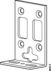
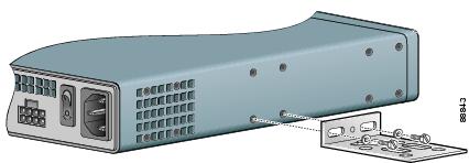
Rack-Mounting the Chassis
Your chassis ships with a pair of brackets for use with a 19-inch rack or mounting on the wall. The bracket is shown in Figure 3-2.
Figure 3-2 Quick Mounting Bracket
Mounting Screws
Two sets of mounting screws are provided, in separate packages. Take care to use each screw type, and washers as needed, in the appropriate locations. Table 3-1 clarifies the differences between rack-mounting and wall-mounting screws.
Attaching the Brackets
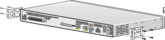
To install the chassis in a rack with the rear panel forward, attach the brackets as shown in Figure 3-3.
Figure 3-3 19-Inch Rack Installation—Rear Panel Forward
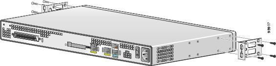
To install the chassis in a center-mount telco rack, attach the brackets as shown in Figure 3-4.
Figure 3-4 Telco 19-Inch Rack Installation—Rear Panel Forward
Installing the Cisco VG224 Voice Gateway in a Rack
The following warning applies only when the unit is rack-mounted:
To rack-mount the chassis, follow this procedure:
Step 1 ![]() Choose one of the methods shown in Figure 3-3, or Figure 3-4, and attach the long leg of the mounting brackets to the chassis, as shown.
Choose one of the methods shown in Figure 3-3, or Figure 3-4, and attach the long leg of the mounting brackets to the chassis, as shown.
Screws are included for attaching the brackets to the chassis, but not for installing the chassis in a rack or on a wall. You need four additional machine screws to install the chassis in a rack. Use the screw size required by your rack. After the brackets are secured to the chassis, you can rack-mount the chassis.
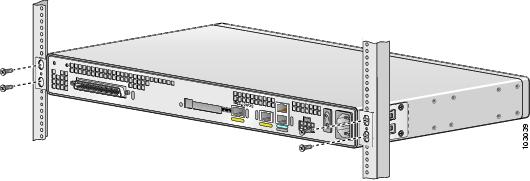
Step 2 ![]() Using screws that you provide, attach the chassis to the rack as shown in Figure 3-5.
Using screws that you provide, attach the chassis to the rack as shown in Figure 3-5.
Figure 3-5 Attaching the Chassis to the 19-Inch Rack
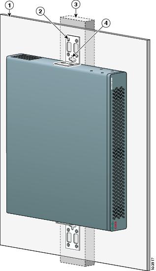
Wall-Mounting the Chassis
The following warning applies only when the unit is wall-mounted:

Note ![]() For information about obtaining the chassis guard, refer to field notice number 28655, VG224 Chassis Guard - Safety Regulation, at http://www.cisco.com/en/US/ts/fn/200/fn28655.html.
For information about obtaining the chassis guard, refer to field notice number 28655, VG224 Chassis Guard - Safety Regulation, at http://www.cisco.com/en/US/ts/fn/200/fn28655.html.
To wall-mount the chassis, follow this procedure:
Step 1 ![]() Attach the short leg of one bracket to the chassis, as shown in Figure 3-6, using two 6-32 x 1/4 slotted hex screws (provided). Be sure to use a plastic washer (provided) with each screw; the narrow end of the washer must fit into the bracket slot, facing the chassis.
Attach the short leg of one bracket to the chassis, as shown in Figure 3-6, using two 6-32 x 1/4 slotted hex screws (provided). Be sure to use a plastic washer (provided) with each screw; the narrow end of the washer must fit into the bracket slot, facing the chassis.
Figure 3-6 Attaching the Brackets for Wall-Mounting
Step 2 ![]() Attach the second bracket to the opposite side of the chassis.
Attach the second bracket to the opposite side of the chassis.
Step 3 ![]() Attach the router to the wall using the brackets previously attached and attachment hardware that you provide as follows:
Attach the router to the wall using the brackets previously attached and attachment hardware that you provide as follows:
•![]() You can install a starter screw in the wall, and hook the bracket keyhole over the screw. This holds the unit in place for easy installation of the attachment screws.
You can install a starter screw in the wall, and hook the bracket keyhole over the screw. This holds the unit in place for easy installation of the attachment screws.
•![]() Attach both brackets to the wall.
Attach both brackets to the wall.
Note ![]() For attaching to a wall stud, each bracket requires two #10 wood screws (round- or pan-head) with #10 washers, or two #10 washer-head screws. The screws must be long enough to penetrate at least 3/4 inch (20 mm) into supporting wood or metal wall stud.
For attaching to a wall stud, each bracket requires two #10 wood screws (round- or pan-head) with #10 washers, or two #10 washer-head screws. The screws must be long enough to penetrate at least 3/4 inch (20 mm) into supporting wood or metal wall stud.
Note ![]() For hollow-wall mounting, each bracket requires two wall anchors with washers. Wall anchors and washers must be size #10.
For hollow-wall mounting, each bracket requires two wall anchors with washers. Wall anchors and washers must be size #10.
•![]() Figure 3-7 shows the orientation required for installation.
Figure 3-7 shows the orientation required for installation.
Figure 3-7 Wall-Mounting the Chassis
|
|
Wall |
|
Wall stud |
|
|
Bracket |
|
Keyhole for starter screw |
Bench-Top Installation
Step 1 ![]() Verify that there is a suitable AC power outlet available.
Verify that there is a suitable AC power outlet available.
Step 2 ![]() Place the four rubber feet (from the accessory kit) in the four indentations on the underside of the chassis.This helps provide proper airflow through and around the chassis.
Place the four rubber feet (from the accessory kit) in the four indentations on the underside of the chassis.This helps provide proper airflow through and around the chassis.
Step 3 ![]() Place the Cisco VG224 voice gateway on a smooth, flat surface.
Place the Cisco VG224 voice gateway on a smooth, flat surface.
Installing the Ground Connection
|
Warning |
|
Warning |
You must connect the chassis to a reliable earth ground; the ground wire must be installed in accordance with local electrical safety standards.
•![]() For NEBS-compliant grounding, use size AWG 6 (13 mm2) wire and the ground lug provided in the accessory kit.
For NEBS-compliant grounding, use size AWG 6 (13 mm2) wire and the ground lug provided in the accessory kit.
•![]() For NEC-compliant grounding, use size AWG 14 (2 mm2) or larger wire and an appropriate user-supplied ring terminal.
For NEC-compliant grounding, use size AWG 14 (2 mm2) or larger wire and an appropriate user-supplied ring terminal.
•![]() For EN/IEC 60950-compliant grounding, use size AWG 18 (1 mm2) or larger wire and an appropriate user-supplied ring terminal.
For EN/IEC 60950-compliant grounding, use size AWG 18 (1 mm2) or larger wire and an appropriate user-supplied ring terminal.
To ground the chassis, follow this procedure:
Step 1 ![]() Locate a suitable ground location.
Locate a suitable ground location.
Tip ![]() Use a multimeter to measure the resistance between various ground locations, such as the following:
Use a multimeter to measure the resistance between various ground locations, such as the following:
•![]() Between the ground of a junction box (outlet) and the ground of a power tap
Between the ground of a junction box (outlet) and the ground of a power tap
•![]() Between the ground of a junction box and a metal water pipe
Between the ground of a junction box and a metal water pipe
•![]() Between the Cisco VG224 voice gateway chassis and the ground of a power tap
Between the Cisco VG224 voice gateway chassis and the ground of a power tap
•![]() Between the Cisco VG224 voice gateway chassis and the ground of a junction box
Between the Cisco VG224 voice gateway chassis and the ground of a junction box
A good ground connection should read between 0.0 and 0.5 ohms.
Step 2 ![]() Strip one end of the ground wire to the length required for the ground lug or terminal.
Strip one end of the ground wire to the length required for the ground lug or terminal.
•![]() For the NEBS ground lug—approximately 0.75 in. (20 mm)
For the NEBS ground lug—approximately 0.75 in. (20 mm)
•![]() For user-provided ring terminal—as required
For user-provided ring terminal—as required
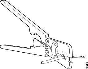
Step 3 ![]() Crimp the ground wire to the ground lug or ring terminal, using a crimp tool of the appropriate size. (See Figure 3-8.)
Crimp the ground wire to the ground lug or ring terminal, using a crimp tool of the appropriate size. (See Figure 3-8.)
Figure 3-8 Crimping a Ground Lug onto the Ground Wire
Step 4 ![]() Attach the ground lug or ring terminal to the chassis as shown in Figure 3-9 or Figure 3-10. For the ground lug, use the two screws with captive locking washers provided. For a ring terminal, use one of the screws provided. Use a number 2 Phillips screwdriver, and tighten the screws to a torque of 8 to 10 in-lb (0.9 to 1.1 N-m).
Attach the ground lug or ring terminal to the chassis as shown in Figure 3-9 or Figure 3-10. For the ground lug, use the two screws with captive locking washers provided. For a ring terminal, use one of the screws provided. Use a number 2 Phillips screwdriver, and tighten the screws to a torque of 8 to 10 in-lb (0.9 to 1.1 N-m).
Note ![]() You can orient the crimped end of the ground lug in either direction (right or left).
You can orient the crimped end of the ground lug in either direction (right or left).
Step 5 ![]() Connect the other end of the ground wire to a grounding point at your site.
Connect the other end of the ground wire to a grounding point at your site.
Figure 3-9 NEBS-Compliant Chassis Ground Connection Using Ground Lug
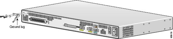
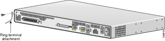
Figure 3-10 Chassis Ground Connection Using Ring Terminal
Connecting Cables
For cables not included with your Cisco VG224 voice gateway, pinout information is in "Cable Specifications and Information." Cisco VG224 voice gateway ports are color-coded for identification.
|
Warning |
Table 3-2 shows the results of the NEBS Type 1/3 power cross tests (tip/ring to ground) performed on the Cisco VG224 voice gateway FXS ports.
|
|
|
|---|---|
50 V/0.33 A; 15 minutes |
Pass |
100 V/0.17 A; 15 minutes |
Pass |
200 V/1.00 A; 1-second pulses, 60 repetitions |
Pass |
Note ![]() The installation must comply with all applicable codes.
The installation must comply with all applicable codes.
LAN and Power Cables
These cables and connections are described in Table 3-3 and in Figure 3-11.
|
|
|
|
|
|---|---|---|---|
Fast Ethernet |
Yellow |
Fast Ethernet switch |
Straight-through Fast Ethernet cable (not included) |
Console |
Light blue |
PC or ASCII terminal communication (COM) port |
RJ-45-to-DB9 console cable (included) |
Auxiliary |
Black |
Modem for remote access |
RJ-45-to-DB25 auxiliary cable (included) |
Power (not shown) |
Power |
100-240 VAC, 50-60 Hz |
Grounding power cord (included)1 |
1 Power cables vary to meet local requirements. |
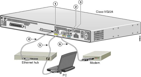
Figure 3-11 LAN and Administrative Access Connections
|
|
Fast Ethernet port |
|
Fast Ethernet (straight-through) |
|
|
Console port |
|
RJ-45-to-DB9 console cable |
|
|
AUX port |
|
RJ-45-to-DB25 auxiliary cable |
Connecting the Input Power
Cable
Use the AC power cable.
Procedure
Step 1 ![]() Connect the AC power cable (supplied) to the recessed power plug on the rear of the concentrator.
Connect the AC power cable (supplied) to the recessed power plug on the rear of the concentrator.
Step 2 ![]() Plug the cable into a power source with a voltage of 100 to 240 VAC.
Plug the cable into a power source with a voltage of 100 to 240 VAC.
Connecting the Console Port to a PC or an ASCII Terminal
Use the procedure in this section to connect the console port to a PC running terminal emulation software.
Note ![]() The console port does not support hardware flow control.
The console port does not support hardware flow control.
Cable
Use an RJ-45-to-RJ-DB-9 console cable (see item 5 in Figure 3-11)
For pinouts, see Table A-1 and Table A-2 in "Cable Specifications and Information."
Procedure
Step 1 ![]() Configure the terminal emulation software requirements:
Configure the terminal emulation software requirements:
9600 baud
8 data bits
1 stop bit
no parity
no flow control
Connecting the Auxiliary Port to a Modem
Use the procedure in this section to connect the auxiliary port to a modem.
Cable
Use an RJ-45-to-DB25 auxiliary cable (labeled Modem).
For pinouts, see Table A-3 and Table A-4 in "Cable Specifications and Information."
Procedure
Step 1 ![]() Connect the cable from the auxiliary port (black) to the DB-25 port on the modem. (See item 6 in Figure 3-11.)
Connect the cable from the auxiliary port (black) to the DB-25 port on the modem. (See item 6 in Figure 3-11.)
Step 2 ![]() Configure the modem.
Configure the modem.
a. ![]() Match the transmission speed of the auxiliary port (default is 9600 baud).
Match the transmission speed of the auxiliary port (default is 9600 baud).
b. ![]() Set the hardware flow control for Data Carrier Detect (DCD) and Data Terminal Ready (DTR) operation.
Set the hardware flow control for Data Carrier Detect (DCD) and Data Terminal Ready (DTR) operation.
Note ![]() The baud rate for the auxiliary (and console) port can be configured in software for 1200, 2400, 4800, 19200, 38400, 57600, and 115200.
The baud rate for the auxiliary (and console) port can be configured in software for 1200, 2400, 4800, 19200, 38400, 57600, and 115200.
Connecting the Fast Ethernet Port to the Fast Ethernet Switch
Use the procedure in this section to connect a Fast Ethernet port to the Fast Ethernet switch.
Cable
Use a straight-through Fast Ethernet cable (not included).
Procedure
Step 1 ![]() Connect the cable from a Fast Ethernet port to an available port on the Fast Ethernet switch. (See item 4 in Figure 3-11.)
Connect the cable from a Fast Ethernet port to an available port on the Fast Ethernet switch. (See item 4 in Figure 3-11.)
Step 2 ![]() Connect the second cable if it is required.
Connect the second cable if it is required.
Note ![]() Not all models have two ports.
Not all models have two ports.
Voice Cables
The analog FXS voice cables and connections are:
|
|
|
|
|---|---|---|
RJ-21 |
Distribution panel |
RJ-21-to-RJ-21 straight-through cable (not included) |
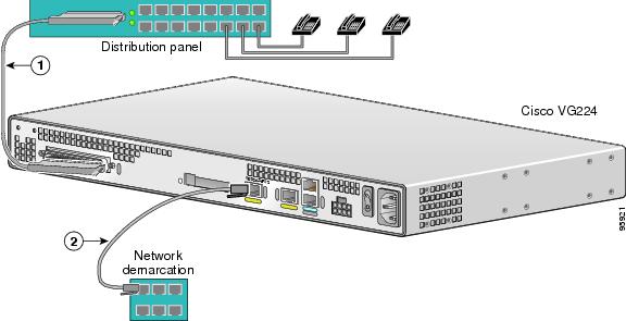
Figure 3-12 WAN and Voice Connections
|
|
RJ-21 cable |
|
RJ-45 cable (through a patch panel) to central office |
Connecting the Analog Voice Interface to a Distribution Panel
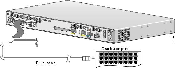
To connect the multiport analog voice interface to a distribution panel, which connects to telephones, faxes, or analog PBX equipment, use the following procedure. (See Figure 3-13.)
Cable
Use an RJ-21 cable with Amphenol 50-pin connectors (not included).
For RJ-21X/CA21A pinouts, see Table A-5 in "Cable Specifications and Information."
Procedure
Step 1 ![]() Connect the RJ-21 cable from the analog voice multiport to the distribution panel.
Connect the RJ-21 cable from the analog voice multiport to the distribution panel.
Step 2 ![]() Secure the cable in place using the strap.
Secure the cable in place using the strap.
Figure 3-13 Analog Voice Connection
Ports, Connectors, and Pinouts
Table 3-4 summarizes the cable connections between Cisco VG224 voice gateway and the network and user interfaces. Find the port and the equipment or network type in the table; then look at the applicable pinout table in "Cable Specifications and Information."
Remote Terminal Connections (If Applicable)
If you are configuring a Cisco VG224 voice gateway from a remote location, connect the modem and the remote PC or terminal to the telephone network as described in this section.
Connecting to a Modem
To connect the local modem and the remote modem to live telephone outlets, use standard telephone cables.
Connecting to a Remote PC
To link a Cisco VG224 voice gateway to a remote PC, use the following procedure:
Note ![]() The remote PC must be running terminal emulation software.
The remote PC must be running terminal emulation software.
Step 1 ![]() Connect the remote PC and modem.
Connect the remote PC and modem.
Step 2 ![]() Set the PC terminal emulation software requirements:
Set the PC terminal emulation software requirements:
9600 baud
8 data bits
1 stop bit
no parity
no flow control.
Step 3 ![]() Key in and dial the telephone number of the Cisco VG224 voice gateway external modem.
Key in and dial the telephone number of the Cisco VG224 voice gateway external modem.
Connecting to a Remote ASCII Terminal
To link a Cisco VG224 voice gateway to a remote ASCII terminal, such as a VT100, use the following procedure:
Step 1 ![]() Connect the remote ASCII terminal and modem.
Connect the remote ASCII terminal and modem.
Step 2 ![]() Set the terminal requirements:
Set the terminal requirements:
9600 baud
8 data bits
1 stop bit
no parity
no flow control.
Step 3 ![]() Key in the telephone number of the Cisco VG224 voice gateway external modem, or, if you are using a Hayes-compatible modem, enter ATDT and the number to be dialed.
Key in the telephone number of the Cisco VG224 voice gateway external modem, or, if you are using a Hayes-compatible modem, enter ATDT and the number to be dialed.
Connecting Backup Power
A Cisco VG224 voice gateway can be installed with optional backup power. Backup power to a DC-powered chassis is provided by a 12-volt battery backup system; see the "Connecting a Backup Battery to a DC-Powered Cisco VG224" section for connection instructions. Backup power to an AC-powered chassis is provided by an uninterruptible power supply (UPS); see the "Connecting a UPS to an AC-Powered Cisco VG224" section for connection instructions.
The maximum power requirement for the Cisco VG224 voice gateway is 70 W.
Connecting a Backup Battery to a DC-Powered Cisco VG224
Connect a 12-volt backup battery to the DC input connector on your Cisco VG224 voice gateway. Before you install a backup battery, be sure to read the installation instructions for the backup battery equipment.
Figure 3-14 shows a setup using an external backup battery.
Note ![]() Figure 3-14 shows one possible setup; please review your backup battery documents before setting up your system.
Figure 3-14 shows one possible setup; please review your backup battery documents before setting up your system.
Figure 3-14 Connecting a Battery Backup to a DC-Powered Cisco VG224
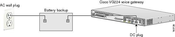
Note ![]() We recommend a 12-volt automotive battery if you require longer periods of battery backup (up to 8 hours).
We recommend a 12-volt automotive battery if you require longer periods of battery backup (up to 8 hours).
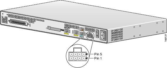
Figure 3-15 shows the DC power connector. See Table 3-5 for pinout information for the DC power connector on the Cisco VG224 voice gateway.
Figure 3-15 DC Power Connector
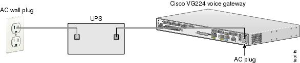
Connecting a UPS to an AC-Powered Cisco VG224
Connect an uninterruptible power supply to the AC input on your Cisco VG224 voice gateway. Before you install a UPS, be sure to read the installation instructions for the UPS.
Figure 3-16 shows a setup using a UPS.
Note ![]() Figure 3-16 shows one possible setup; please review your UPS documents before setting up your system.
Figure 3-16 shows one possible setup; please review your UPS documents before setting up your system.
Figure 3-16 Connecting a UPS to an AC-Powered Cisco VG224
 Feedback