Installing the Cisco Asynchronous Serial NIM - 16/24 Port for Cisco 4000 Series ISRs
OL-31532-01
This document provides information that you should know before and during the installation of the Cisco Asynchronous Serial NIM - 16/24 Port in the Cisco 4000 Series Integrated Services Routers (ISRs). This document contains the following sections:
About the Cisco Asynchronous Serial NIM - 16/24 Port
The Cisco Asynchronous Serial NIM - 16/24 Port are multi-protocol asynchronous serial network interface modules (NIMs) supported on the Cisco 4000 Series ISRs. This module allows the Cisco 4000 Series ISR platforms to act as a terminal server for out-of-band management of other network and server devices in the network. The feature functionalities are in line with the HWIC-16A module for the ISR-G1 & ISR-G2 series.
Table 1 lists the Cisco Asynchronous Serial NIM - 16/24 Port SKUs.
|
SKUs |
Description |
Supported Interfaces |
|---|---|---|
|
NIM-16A |
16-Port Async Serial NIM |
RS232 |
|
NIM-24A |
24-Port Async Serial NIM |
RS232 |
 Note |
The Cisco Asynchronous Serial NIM-16/24 Port for Cisco 4000 Series ISRs does not support Serial Line Internet Protocol (SLIP) and Point-to-Point Protocol (PPP). |
The Cisco Asynchronous Serial NIM - 16/24 Port for Cisco 4000 Series ISRs family consists of 2 compact serial NIM SKUs in single-wide NIM form factor. 16-port NIM: Front Panel shows the front panel of the 16-port serial NIM, 24-port NIM: Front Panel shows the front panel of the 24-port serial NIM, and Exploded View of the 16-port NIM: Front Panel show the front panel of the 4-port serial NIM, respectively. The LEDs for each port can be located at the bottom of the port. The EN and COMM LEDs are a bi-color LEDs.
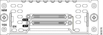
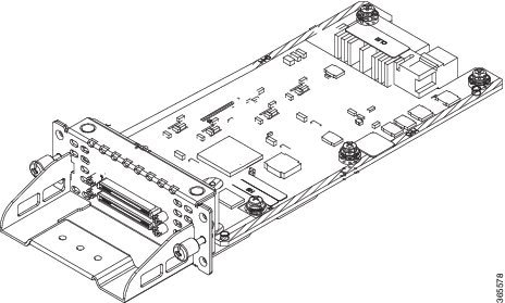
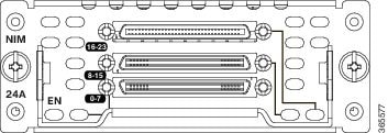
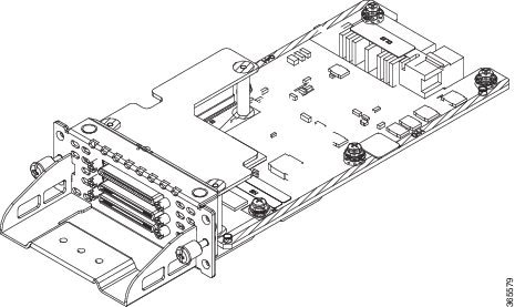
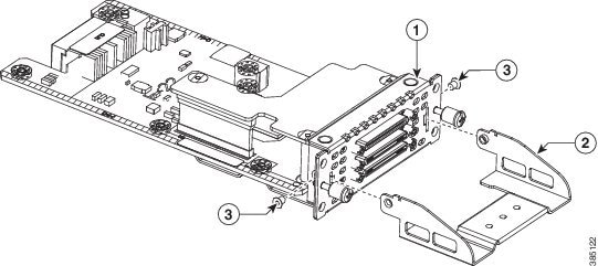
|
1 |
Screws |
|
2 |
Bracket |
|
3 |
Connector Mounting Screws |
LEDs
The Cisco Asynchronous Serial NIM 16-port has 3 LEDs and 24-port has 4 LEDs to display module and port statuses.
|
NIM 16-A LED Usage |
NIM 24-A LED Usage |
|---|---|
|
1 LED for module status |
1 LED for module status |
|
1 LED for port 0-7 status |
1 LED for port 0-7 status |
|
1 LED for port 8-15 status |
1 LED for port 8-15 status |
|
1 LED for port 16-23 status |
The LEDs for each port are located on the front panel and are described in the table below.
|
LED |
Color |
Description |
|---|---|---|
|
EN |
Green or Amber |
Off: Default state when the module is powered on for the first time. Green: The module is powered on and is functioning correctly. Amber: The module has some failure. You can also set this state when the module is powered down. |
|
Port (CONN) LED |
Green |
Off: No port is configured. Green On: All ports are configured. Blinking Green: At least one of the port is passing traffic. |
Cables Supported
For Cisco Asynchronous Serial NIM - 16/24 Port, a new cable CAB-ASYNC-8 is introduced. The 16-port NIM has two sockets. Both the new and old cables can be plugged-in into both the sockets. The 24-port NIM has three sockets. New cables can be plugged-in into all the sockets. Old cables only can be plugged-in into sockets 1 and 3. The following table lists the cable supported:
|
16-Port |
24-Port |
|---|---|
|
Socket 1- CAB-HD8-ASYNC/CAB-ASYNC-8 (old cable/new cable) |
Socket 1- CAB-HD8-ASYNC/CAB-ASYNC-8 (old cable/new cable) |
|
Socket 2 - CAB-HD8-ASYNC/CAB-ASYNC-8 (old cable/new cable) |
Socket 2- CAB-ASYNC-8 (new cable) |
|
Socket 3- CAB-HD8-ASYNC/CAB-ASYNC-8 (old cable/new cable) |
Recommended Practices for Cisco Asynchronous Serial NIM - 16/24 Port
This section describes recommended practices for safe and effective installation of the hardware described in this document.
Safety warnings included in this section apply to the Cisco Asynchronous Serial NIM - 16/24 Port that are used on the Cisco 4000 Series ISRs.
Safety Recommendations
To prevent hazardous conditions, follow these safety recommendations while working with this equipment:
-
Keep tools away from walk areas where you or others could fall over them.
-
Do not wear loose clothing around the router. Fasten your tie or scarf and roll up your sleeves to prevent clothing from being caught in the chassis.
-
Wear safety glasses when working under any conditions that might be hazardous to your eyes.
-
Locate the emergency power-off switch in the room before you start working. If an electrical accident occurs, shut the power off.
-
Before working on the router, turn off the power and unplug the power cord.
-
Disconnect all power sources before doing the following:
-
Installing or removing a router chassis
-
Working near power supplies
-
-
Do not work alone if potentially hazardous conditions exist.
-
Always check that power is disconnected from a circuit.
-
Remove possible hazards from your work area, such as damp floors, ungrounded power extension cables, or missing safety grounds.
-
If an electrical accident occurs, proceed as follows:
-
Use caution; do not become a victim yourself.
-
Turn off power to the room using the emergency power-off switch.
-
Determine the condition of the victim and send another person to get medical aid or call for help.
-
Determine if the person needs rescue breathing or external cardiac compressions; then take appropriate action.
-
Preventing Electrostatic Discharge Damage
Electrostatic discharge can damage equipment and electrical circuitry. Electrostatic discharge occurs when electronic printed circuit cards, such as those used in Installing the Cisco Multiprotocol Synchronus Serial NIM, are improperly handled and can result in complete or intermittent equipment failure. Always observe the following electrostatic discharge damage (ESD) prevention procedures when installing, removing, or replacing any electronic printed circuit cards:
-
Make sure that the router chassis is electrically connected to earth ground.
-
Wear an ESD-preventive wrist strap, and make sure that it makes good contact with your skin
. -
Connect the wrist strap clip to an unpainted portion of the chassis frame to channel unwanted ESD voltages to ground.
 Caution |
The wrist strap and clip must be used correctly to ensure proper ESD protection. Periodically confirm that the resistance value of the ESD-preventive wrist strap is between 1 and 10 megohms (Mohm). |
-
If no wrist strap is available, ground yourself by touching the metal part of the router chassis.
General Maintenance Guidelines
The following maintenance guidelines apply to the Cisco Asynchronous Serial NIM-16/24 port and SM-X-64 port for Cisco 4000 Series ISRs:
-
Keep the router chassis area clear and dust-free during and after installation.
-
If you remove the chassis cover for any reason, store it in a safe place.
-
Do not perform any action that creates a hazard to people or makes equipment unsafe.
-
Keep walk areas clear to prevent falls or damage to equipment.
-
Follow installation and maintenance procedures as documented by Cisco Systems, Inc.
Safety Warnings
The following safety warning statements apply to all hardware procedures involving the Cisco Asynchronous Serial NIM-16/24-port and SM-X-64-port for Cisco 4000 Series ISRs. Translations of these warnings are available in the Cisco Network Modules and Interface Cards Regulatory Compliance and Safety Information document, which ships with all individual Cisco Asynchronous Serial NIM-16/24-port and SM-X-port for Cisco 4000 Series ISRs orders, and is also available on Cisco.com.
 Warning |
IMPORTANT SAFETY INSTRUCTIONS This warning symbol means danger. You are in a situation that could cause bodily injury. Before you work on any equipment, be aware of the hazards involved with electrical circuitry and be familiar with standard practices for preventing accidents. Use the statement number provided at the end of each warning to locate its translation in the translated safety warnings that accompanied this device. Statement 1071 SAVE THESE INSTRUCTIONS |
 Warning |
Read the installation instructions before connecting the system to the power source. Statement 1004 |
 Warning |
To reduce the risk of fire, use only No. 26 AWG or larger telecommunication line cord. Statement 1023 |
 Warning |
This unit might have more than one power supply connection. All connections must be removed to de-energize the unit. Statement 1028 |
 Warning |
Only trained and qualified personnel should be allowed to install, replace, or service this equipment. Statement 1030 |
 Warning |
Do not use this product near water; for example, near a bath tub, wash bowl, kitchen sink or laundry tub, in a wet basement, or near a swimming pool. Statement 1035 |
 Warning |
Never install telephone jacks in wet locations unless the jack is specifically designed for wet locations. Statement 1036 |
 Warning |
Never touch uninsulated telephone wires or terminals unless the telephone line has been disconnected at the network interface. Statement 1037 |
 Warning |
Avoid using a telephone (other than a cordless type) during an electrical storm. There may be a remote risk of electric shock from lightning. Statement 1038 |
 Warning |
To report a gas leak, do not use a telephone in the vicinity of the leak. Statement 1039 |
 Warning |
Ultimate disposal of this product should be handled according to all national laws and regulations. Statement 1040 |
 Warning |
When installing or replacing the unit, the ground connection must always be made first and disconnected last. Statement 1046 |
The following warnings apply in Australia:
 Warning |
Before working on equipment that is connected to power lines, remove jewelry (including rings, necklaces, and watches). Metal objects will heat up when connected to power and ground and can cause serious burns or weld the metal object to the terminals. Statement 43 |
 Warning |
Because invisible laser radiation may be emitted from the aperture of the port when no fiber cable is connected, avoid exposure to laser radiation and do not stare into open apertures. Statement 125 |
 Warning |
Do not work on the system or connect or disconnect cables during periods of lightning activity. Statement 1001 |
 Warning |
To avoid electric shock, do not connect safety extra-low voltage (SELV) circuits to telephone-network voltage (TNV) circuits. LAN ports contain SELV circuits, and WAN ports contain TNV circuits. Both LAN and WAN ports may use RJ-45 connectors. Use caution when connecting cables. Statement 1021 |
 Warning |
Hazardous network voltages are present in WAN ports regardless of whether power to the router is OFF or ON. To avoid electric shock, use caution when working near WAN ports. When detaching cables, detach the end away from the router first. Statement 1026 |
 Warning |
Before opening the chassis, disconnect the telephone-network cables to avoid contact with telephone-network voltages. Statement 1041 |
 Warning |
The telecommunications lines must be disconnected 1) before unplugging the main power connector and/or 2) while the housing is open. Statement 1043 |
Configuring NIM-16A and NIM-24A as a Terminal Server
It provides console level access to multiple Cisco devices for remote configuration and management.
The NIM-16A and
NIM-24A modules are used to provide out of band connectivity to the console
ports of other devices. On the 16- and 24-port async modules, the interfaces
are addressed as
interface async
                     		  <slot/subslot/port>
.
Prerequisites for Configuring NIM-16A and NIM-24A as a Terminal Server
You must have privileged EXEC access to the router's command line interface (CLI). For more information on using the command line and for understanding command modes, see Using Cisco IOS Software.
For instructions on connecting a console to your router, refer to the documentation that accompanied your router, or refer to the online documentation for your equipment.
How to Configure NIM-16A and NIM-24A as a Terminal Server
Perform the following steps to configure. In the below mentioned configuration steps a basic terminal server function is configured using default parameters.
-
From privileged EXEC mode, enter the configure command.
router#configure terminal
Enter configuration commands, one per line. End with CNTL/Z.
-
router(config)#ip vrf Mgmt-intf
!--- If not done already, create management vrf globally (in this example vrf Mgmt-intf )
-
router(config-vrf)#interface GigabitEthernet0
-
router(config-if)#vrf forwarding Mgmt-intf
!--- Assign interface GigabitEthernet0 to vrf Mgmt-intf
-
router(config-if)#ip address 10.75.163.95 255.255.255.0
!--- Use a public IP address to ensure connectivity
-
router(config-if)#ip route vrf Mgmt-intf 0.0.0.0 0.0.0.0 10.75.163.1
!--- configure correct route to gateway in vrf Mgmt-intf
-
router(config)#line 0/1/0
!--- switch to Line configuration mode for asynchronous port configuration
-
router(config-line)#transport input all
!--- Defines the protocols to use when connecting to a specific line of the device. In this case all protocols (default)
-
router(config-line)#no exec
!--- Allow an outgoing connection only
Optional Parameters
transport input all [databits] [parity] [speed]
|
[databits] |
Sets the number of data bits per character that are interpreted and generated by the router hardware. |
|
[parity] |
Sets terminal parity. Need to sync with device console. |
|
[speed] |
Sets the transmit and receive speeds. Need to sync with device console. |
Verification and Troubleshooting
Use the following show commands for the verification:
router#show running-config
Building configuration...
...

!--- Lines omitted for brevity

ip vrf Mgmt-intf
!
!
interface GigabitEthernet0
 ip vrf forwarding Mgmt-intf
 ip address 10.75.163.95 255.255.255.0
!
ip route vrf Mgmt-intf 0.0.0.0 0.0.0.0 10.75.163.1
!
line 0/1/0
 transport input all
no exec
!
end
Command Summary
The following commands are explained:
- transport input
-
databits
-
parity
-
speed
transport input
Defines the protocols that needs to be used when connecting to the terminal server.
transport input {all | lat | mop | nasi | none | pad | rlogin | ssh | telnet | udptn}
|
all |
All protocols |
|
lat |
DEC LAT protocol |
|
mop |
DEC MOP Remote Console Protocol |
|
nasi |
NASI protocol |
|
none |
No protocols |
|
pad |
X.3 PAD |
|
rlogin |
Unix rlogin protocol |
|
ssh |
TCP/IP SSH protocol |
|
telnet |
TCP/IP Telnet protocol |
|
udptn |
UDPTN async via UDP protocol |
databits
Sets the number of data bits per character that are interpreted and generated by the router hardware. To restore the default value, use the no form of the command.
databits {5 | 6 | 7 | 8}
no databits
|
5 |
Five data bits per character. |
|
6 |
Six data bits per character. |
|
7 |
Seven data bits per character. |
|
8 |
Eight data bits per character (default). |
 Note |
Only 7 and 8 data bits work. |
parity
Defines generation of a parity bit. To specify no parity, use the no form of this command.
parity {none | even | odd | space | mark}
no parity
|
none |
No parity (Default) |
|
even |
Even parity |
|
odd |
Odd parity |
|
space |
Space parity |
|
mark |
Mark parity |
Usage Guideline: Need to sync between Device Console line and Terminal Server TTY line.
speed
Sets the transmit and receive speed.
|
<0-4294967295> |
Baud rate in bits per second (bps). |
Default speed is 9600.
Usage Guideline: Need to sync between Device Console line and Terminal Server TTY line.
show line
Use show line command to check all the TTY line summary information. The output contains information about mapping between async interface and line number, the line speed, uses, noise and so on. The line that begins with the asterisk "*" indicates that the line is in use.
Router#show  line
   Tty Line Typ     Tx/Rx    A Modem  Roty AccO AccI  Uses  Noise Overruns  Int
*     0    0 CTY              -    -      -    -    -     0      0    0/0      -
      1    1 AUX   9600/9600  -    -      -    -    -     0      0    0/0      -
* 0/1/0    2 TTY   9600/9600  -    -      -    -    -     1      7    0/0      -
  0/1/1    3 TTY   9600/9600  -    -      -    -    -     0      7    0/0      -
  0/1/2    4 TTY   9600/9600  -    -      -    -    -     0      7    0/0      -
  0/1/3    5 TTY   9600/9600  -    -      -    -    -     0      7    0/0      -
  0/1/4    6 TTY   9600/9600  -    -      -    -    -     0      7    0/0      -
  0/1/5    7 TTY   9600/9600  -    -      -    -    -     0      7    0/0      -
  0/1/6    8 TTY   9600/9600  -    -      -    -    -     0      7    0/0      -
  0/1/7    9 TTY   9600/9600  -    -      -    -    -     0      6    0/0      -
  0/1/8   10 TTY   9600/9600  -    -      -    -    -     0      7    0/0      -
  0/1/9   11 TTY   9600/9600  -    -      -    -    -     0      7    0/0      -
 0/1/10   12 TTY   9600/9600  -    -      -    -    -     0      7    0/0      -
 0/1/11   13 TTY   9600/9600  -    -      -    -    -     0      7    0/0      -
 0/1/12   14 TTY   9600/9600  -    -      -    -    -     0      7    0/0      -
 0/1/13   15 TTY   9600/9600  -    -      -    -    -     0      7    0/0      -
 0/1/14   16 TTY   9600/9600  -    -      -    -    -     0      7    0/0      -
 0/1/15   17 TTY   9600/9600  -    -      -    -    -     0      7    0/0      -
 0/1/16   18 TTY   9600/9600  -    -      -    -    -     0      7    0/0      -
 0/1/17   19 TTY   9600/9600  -    -      -    -    -     0      7    0/0      -
 0/1/18   20 TTY   9600/9600  -    -      -    -    -     0      7    0/0      -
 0/1/19   21 TTY   9600/9600  -    -      -    -    -     0      7    0/0      -
 0/1/20   22 TTY   9600/9600  -    -      -    -    -     0      7    0/0      -
 0/1/21   23 TTY   9600/9600  -    -      -    -    -     0      7    0/0      -
 0/1/22   24 TTY   9600/9600  -    -      -    -    -     0      7    0/0      -
 0/1/23   25 TTY   9600/9600  -    -      -    -    -     0      7    0/0      -
*   866  866 VTY              -    -      -    -    -    19      0    0/0      -
*   867  867 VTY              -    -      -    -    -    32      0    0/0      -
    868  868 VTY              -    -      -    -    -    13      0    0/0      -
    869  869 VTY              -    -      -    -    -     0      0    0/0      -
    870  870 VTY              -    -      -    -    -     0      0    0/0      -
Line(s) not in async mode -or- with no hardware support:
26-865
You can also use show line <line number> command to get the TTY line detail information. It gives you the information about the configured or by default parameters on that TTY line.
Router#show line 2
   Tty Line Typ     Tx/Rx    A Modem  Roty AccO AccI  Uses  Noise Overruns  Int
* 0/1/0    2 TTY   9600/9600  -    -      -    -    -     1      7    0/0      -

Line 0/1/0, Location: "", Type: "XTERM"
Length: 24 lines, Width: 117 columns
Baud rate (TX/RX) is 9600/9600, no parity, 2 stopbits, 8 databits
Status: Ready, Connected, Active
Capabilities: EXEC Suppressed
Modem state: Ready
Group codes:    0
Special Chars: Escape  Hold  Stop  Start  Disconnect  Activation
                ^^x    none   -     -       none
Timeouts:      Idle EXEC    Idle Session   Modem Answer  Session   Dispatch
                never         never                        none     not set
                            Idle Session Disconnect Warning
                              never
                            Login-sequence User Response
                             00:00:30
                            Autoselect Initial Wait
                              not set
Modem type is unknown.
Session limit is not set.
Time since activation: 00:24:46
Editing is enabled.
History is enabled, history size is 10.
DNS resolution in show commands is enabled
Full user help is disabled
Allowed input transports are lat pad telnet rlogin mop udptn nasi ssh acercon.
Allowed output transports are lat pad telnet rlogin mop nasi ssh.
Preferred transport is lat.
Shell: enabled
Shell trace: off
No output characters are padded
No special data dispatching characters
show interface
Use show interface async <slot/subslot/interface> command to get the async interface details including counters of input/output queue, rate, packets, bytes, and so on.
Router#show interfaces async 0/1/0
Async0/1/0 is up, line protocol is down
  Hardware is NIM-24A
  MTU 1500 bytes, BW 17 Kbit/sec, DLY 0 usec,
     reliability 25/255, txload 1/255, rxload 1/255
  Encapsulation ASYNC, loopback not set
  Keepalive not set
  Last input never, output 00:00:00, output hang never
  Last clearing of "show interface" counters never
  Input queue: 0/375/0/0 (size/max/drops/flushes); Total output drops: 0
  Queueing strategy: fifo
  Output queue: 0/0 (size/max)
  5 minute input rate 0 bits/sec, 0 packets/sec
  5 minute output rate 0 bits/sec, 0 packets/sec
     114 packets input, 12608 bytes, 0 no buffer
     Received 0 broadcasts (0 IP multicasts)
     0 runts, 0 giants, 0 throttles
     0 input errors, 0 CRC, 0 frame, 0 overrun, 0 ignored, 0 abort
     17 packets output, 17 bytes, 0 underruns
     0 output errors, 0 collisions, 1 interface resets
     0 unknown protocol drops
     0 output buffer failures, 0 output buffers swapped out
show tcp
Use show tcp <line number> command to get the tcp session detailed information including foreign host, connection state, Event Timers, datagrams counters, and so on.
Router#show tcp 2

tty0/1/0, virtual tty from host 10.75.157.51
Connection state is ESTAB, I/O status: 1, unread input bytes: 0
Connection is ECN Disabled, Mininum incoming TTL 0, Outgoing TTL 255
Local host: 10.75.163.116, Local port: 2002
Foreign host: 10.75.157.51, Foreign port: 17719
Connection tableid (VRF): 1
Maximum output segment queue size: 20

Enqueued packets for retransmit: 0, input: 0  mis-ordered: 0 (0 bytes)

Event Timers (current time is 0x11F2BAC0):
Timer          Starts    Wakeups            Next
Retrans           112          0             0x0
TimeWait            0          0             0x0
AckHold            15          2             0x0
SendWnd             0          0             0x0
KeepAlive           0          0             0x0
GiveUp              0          0             0x0
PmtuAger            0          0             0x0
DeadWait            0          0             0x0
Linger              0          0             0x0
ProcessQ            0          0             0x0

iss: 2183166457  snduna: 2183179079  sndnxt: 2183179079
irs:  334962581  rcvnxt:  334962632

sndwnd:  24656  scale:      0  maxrcvwnd:   4128
rcvwnd:   4078  scale:      0  delrcvwnd:     50

SRTT: 1000 ms, RTTO: 1003 ms, RTV: 3 ms, KRTT: 0 ms
minRTT: 1 ms, maxRTT: 1000 ms, ACK hold: 200 ms
uptime: 1919014 ms, Sent idletime: 1811238 ms, Receive idletime: 1811237 ms
Status Flags: passive open, active open
Option Flags: Retrans timeout
IP Precedence value : 0

Datagrams (max data segment is 536 bytes):
Rcvd: 125 (out of order: 0), with data: 14, total data bytes: 50
Sent: 114 (retransmit: 0, fastretransmit: 0, partialack: 0, Second Congestion: 0), with data: 111, total data bytes: 12621

 Packets received in fast path: 0, fast processed: 0, slow path: 0
 fast lock acquisition failures: 0, slow path: 0
TCP Semaphore      0x7FC594004670  FREE
Async Line Numbering
Asyncronous lines are not numbered in a linear format on the Cisco 4000 Series Integrated Service Routers platform. Due to the modular design of these routers, there are fixed line ranges for each slot and each slot is allocated 24 line numbers. This means that the span of line numbers does not change when you add or remove async lines from other slots. The following table shows the reserved line numbering per slot on Cisco 4000 Series Integrated Service Routers platforms.
For Cisco 4000 Series Integrated Service Routers platforms, line number for async interface starts from 2. Insert the line number only in slot 0/1 and after line number allocation slot 0 is used only in special cases.
96 (24*4) line number is reserved for each slot, and 24 line number for each subslot.
For slot 1 and 2, line number allocation is:
|
Slot |
Subslot |
Reserved Line Numbering |
|---|---|---|
|
0 |
1 |
2-25 |
|
0 |
2 |
26-49 |
|
0 |
3 |
50-73 |
|
1 |
0 |
98-121 |
|
2 |
0 |
194-217 |
Installing the Cisco Asynchronous Serial NIM - 16/24 Port in the Cisco 4000 Series ISRs
This section describes the following installation tasks for Cisco Asynchronous Serial NIM - 16/24 Port for Cisco 4000 Series ISRs.
Tools and Equipment Required During Installation
You will need the following tools and equipment while working with the Cisco Asynchronous Serial NIM-16/24-Port and SM-X-64-Port:
-
Number 1 Phillips screwdriver or a small flat-blade screwdriver
-
ESD-preventive wrist strap
 Warning |
No user-serviceable parts inside. Do not open. Statement 1073 |
 Warning |
Only trained and qualified personnel should be allowed to install, replace, or service this equipment. Statement 1030 |
Installing the Cisco Asynchronous Serial NIM - 16/24 Port in the Cisco 4000 Series ISRs
Procedure
| Step 1 |
Shut down the electrical power to the slot in the router either by turning off the electrical power to the router or by issuing the online insertion and removal (OIR) commands. Leave the power cable plugged in to channel ESD voltages to ground. For more information on OIR, see the “Managing Cisco Enhanced Services and Network Interface Modules” chapter in the Software Configuration Guide for the Cisco 4000 Series Integrated Services Routers. |
||
| Step 2 |
Remove all network cables from the rear panel of the router. |
||
| Step 3 |
Remove the blank faceplates installed over the network interface module slot that you intend to use.
|
||
| Step 4 |
Align the module with the guides in the chassis walls or slot divider and slide it gently into the NIM slot on the router. |
||
| Step 5 |
Push the module into place until you feel the edge connector seat securely into the connector on the router backplane. The module faceplate should contact the chassis rear panel. |
||
| Step 6 |
Using a number 1 Phillips or flat-blade screwdriver, tighten the captive screws on the network interface module. |
||
| Step 7 |
Connect the module to the network and re-enable the power to the slot in the router.
|
Removing the Cisco Asynchronous Serial NIM - 16/24 Port from the Cisco 4000 Series ISRs
Procedure
| Step 1 |
Shut down the electrical power to the slot in the router either by turning off the electrical power to the router or by issuing the online insertion and removal (OIR) commands. Leave the power cable plugged in to channel ESD voltages to ground. For more information on OIR, see the “Managing Cisco Enhanced Services and Network Interface Modules” chapter in the Software Configuration Guide for the Cisco 4451-X Integrated Services Router. |
| Step 2 |
Remove all network cables from the rear panel of the router. |
| Step 3 |
Using a number 1 Phillips or flat-blade screwdriver, loosen the captive screws on the NIM. |
| Step 4 |
Slide the network interface module out. |
| Step 5 |
If you are not replacing the module, install a blank faceplate over the empty slot to ensure proper air flow. |
Connecting the Cisco Asynchronous Serial NIM - 16/24 Port to a Network
To connect the Cisco Asynchronous Serial NIM - 16/24 Port to the network, follow these steps:
Procedure
| Step 1 |
Connect the serial cable to the connector on the NIM faceplate. |
| Step 2 |
Connect the female end of the serial cable to the male end of the other serial connector for back-to-back connectivity. |
| Step 3 |
Connect one end of the appropriate serial cable to the connector on the card faceplate. |
| Step 4 |
Connect the other end of the cable to the DTE or DCE. |
| Step 5 |
Turn on power to the router by pressing the power switch to the ON ( | ) position. |
| Step 6 |
Check that the CONN LED goes on, which indicates that the serial port detects the WAN serial connection. |
Related Documents
|
Related Topic |
Document Title |
|---|---|
|
Information on the Cisco 4451-X Integrated Services Router |
Hardware Installation Guide for the Cisco 4000 Series Integrated Services Routers |
|
Information on configuring Cisco 4451-X Integrated Services Routers |
Software Configuration Guide for the Cisco 4000 Series Integrated Services Routers |
|
Information about configuring the Cisco Asynchronous Serial NIM - 16/24 Port for Cisco 4000 Series ISRs. |
Configuring the Cisco Asynchronous Serial NIM - 16/24 Port High-Speed WAN Interface Cards for Cisco 4000 Series ISRs |
|
Regulatory compliance and safety information |
Cisco Network Modules and Interface Cards Regulatory Compliance and Safety Information |
 Feedback