- Overview of the Cisco 819 Integrated Services Router
- Wireless Device Overview
- Wireless Local Area Network
- 4G LTE Wireless WAN
- Basic Router Configuration
- Configuring Backup Data Lines and Remote Management
- Environment Monitoring
- Configuring the Serial Interface
- Configuring Security Features
- Configuring the Ethernet Switches
- Configuring PPP over Ethernet with NAT
- Configuring a LAN with DHCP and VLANs
- Configuring a VPN Using Easy VPN and an IPSec Tunnel
- Cisco IOS Software Basic Skills
- Concepts
- ROM Monitor
- Common Port Assignments
- Cisco Easy VPN
- Configuration Tasks
- Configure the IKE Policy
- Configure Group Policy Information
- Apply Mode Configuration to the Crypto Map
- Enable Policy Lookup
- Configure IPSec Transforms and Protocols
- Configure the IPSec Crypto Method and Parameters
- Apply the Crypto Map to the Physical Interface
- Create an Easy VPN Remote Configuration
Configuring a VPN Using Easy VPN and an IPSec Tunnel
This chapter provides an overview of the creation of Virtual Private Networks (VPNs) that can be configured on the Cisco 819 Integrated Services Routers (ISRs).
Cisco routers and other broadband devices provide high-performance connections to the Internet, but many applications also require the security of VPN connections that perform a high level of authentication and that encrypt the data between two particular endpoints.
Two types of VPNs are supported—site-to-site and remote access. Site-to-site VPNs are used to connect branch offices to corporate offices, for example. Remote access VPNs are used by remote clients to log in to a corporate network.
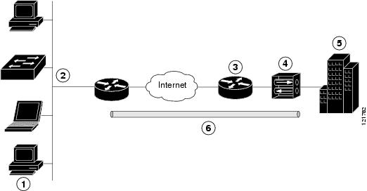
The example in this chapter illustrates the configuration of a remote access VPN that uses the Cisco Easy VPN and an IPSec tunnel to configure and secure the connection between the remote client and the corporate network. Figure 13-1 shows a typical deployment scenario.
Figure 13-1 Remote Access VPN Using IPSec Tunnel
|
|
|
|
|
|
|
|
|
|
|
|
|
|
|
|
|
Cisco Easy VPN
The Cisco Easy VPN client feature eliminates much of the tedious configuration work by implementing the Cisco Unity Client protocol. This protocol allows most VPN parameters, such as internal IP addresses, internal subnet masks, DHCP server addresses, WINS server addresses, and split-tunneling flags, to be defined at a VPN server that is acting as an IPSec server.
An Easy VPN server-enabled device can terminate VPN tunnels initiated by mobile and remote workers who are running Cisco Easy VPN Remote software on PCs. Easy VPN server-enabled devices allow remote routers to act as Easy VPN Remote nodes.
The Cisco Easy VPN client feature can be configured in one of two modes—client mode or network extension mode. Client mode is the default configuration and allows only devices at the client site to access resources at the central site. Resources at the client site are unavailable to the central site. Network extension mode allows users at the central site to access network resources on the client site.
After the IPSec server has been configured, a VPN connection can be created with minimal configuration on an IPSec client, such as a supported Cisco 819 ISR. When the IPSec client initiates the VPN tunnel connection, the IPSec server pushes the IPSec policies to the IPSec client and creates the corresponding VPN tunnel connection.

Note![]() The Cisco Easy VPN client feature supports configuration of only one destination peer. If your application requires the creation of multiple VPN tunnels, you must manually configure the IPSec VPN and Network Address Translation/Peer Address Translation (NAT/PAT) parameters on both the client and the server.
The Cisco Easy VPN client feature supports configuration of only one destination peer. If your application requires the creation of multiple VPN tunnels, you must manually configure the IPSec VPN and Network Address Translation/Peer Address Translation (NAT/PAT) parameters on both the client and the server.
Configuration Tasks
Perform the following tasks to configure your router for this network scenario:
- Configure the IKE Policy
- Configure Group Policy Information
- Apply Mode Configuration to the Crypto Map
- Enable Policy Lookup
- Configure IPSec Transforms and Protocols
- Configure the IPSec Crypto Method and Parameters
- Apply the Crypto Map to the Physical Interface
- Create an Easy VPN Remote Configuration
An example showing the results of these configuration tasks is provided in the “Configuration Example” section.
Note![]() The procedures in this chapter assume that you have already configured basic router features, as well as PPPoE or PPPoA with NAT, DCHP and VLANs. If you have not performed these configurations tasks, see “Basic Router Configuration” section.
The procedures in this chapter assume that you have already configured basic router features, as well as PPPoE or PPPoA with NAT, DCHP and VLANs. If you have not performed these configurations tasks, see “Basic Router Configuration” section.
Note![]() The examples shown in this chapter refer only to the endpoint configuration on the Cisco 819 router. Any VPN connection requires both endpoints be configured properly to function. See the software configuration documentation as needed to configure VPN for other router models.
The examples shown in this chapter refer only to the endpoint configuration on the Cisco 819 router. Any VPN connection requires both endpoints be configured properly to function. See the software configuration documentation as needed to configure VPN for other router models.
Configure the IKE Policy
Perform these steps to configure the Internet Key Exchange (IKE) policy, beginning in global configuration mode:
SUMMARY STEPS
1.![]() crypto isakmp policy priority
crypto isakmp policy priority
2.![]() encryption {des | 3des | aes | aes 192 | aes 256}
encryption {des | 3des | aes | aes 192 | aes 256}
DETAILED STEPS
Configure Group Policy Information
Perform these steps to configure the group policy, beginning in global configuration mode:
SUMMARY STEPS
1.![]() crypto isakmp client configuration group {group-name | default}
crypto isakmp client configuration group {group-name | default}
6.![]() ip local pool {default | poolname } [ low-ip-address [ high-ip-address ]]
ip local pool {default | poolname } [ low-ip-address [ high-ip-address ]]
DETAILED STEPS
|
|
|
|
|---|---|---|
crypto isakmp client configuration group { group-name | default } |
Creates an IKE policy group containing attributes to be downloaded to the remote client. Also enters the Internet Security Association Key and Management Protocol (ISAKMP) group policy configuration mode. |
|
|
|
||
|
|
Specifies the primary Domain Name System (DNS) server for the group. Note You may also want to specify Windows Internet Naming Service (WINS) servers for the group by using the wins command. |
|
|
|
||
|
|
Exits IKE group policy configuration mode and enters global configuration mode. |
|
ip local pool {default | poolname} [low-ip-address [high-ip-address]] |
Specifies a local address pool for the group. For details about this command and additional parameters that can be set, see Cisco IOS Dial Technologies Command Reference. |
Apply Mode Configuration to the Crypto Map
Perform these steps to apply mode configuration to the crypto map, beginning in global configuration mode:
SUMMARY STEPS
1.![]() crypto map map-name isakmp authorization list list-name
crypto map map-name isakmp authorization list list-name
2.![]() crypto map tag client configuration address [initiate | respond]
crypto map tag client configuration address [initiate | respond]
DETAILED STEPS
Enable Policy Lookup
Perform these steps to enable policy lookup through AAA, beginning in global configuration mode:
SUMMARY STEPS
2.![]() aaa authentication login {default | list-name } method1 [ method2 ...]
aaa authentication login {default | list-name } method1 [ method2 ...]
3.![]() aaa authorization {network | exec | commands level | reverse-access | configuration} {default | list-name } [ method1 [ method2 ...]]
aaa authorization {network | exec | commands level | reverse-access | configuration} {default | list-name } [ method1 [ method2 ...]]
4.![]() username name {nopassword | password password | password encryption-type encrypted-password }
username name {nopassword | password password | password encryption-type encrypted-password }
DETAILED STEPS
|
|
|
|
|---|---|---|
|
|
||
aaa authentication login {default | list-name} method1 [method2...] |
Specifies AAA authentication of selected users at login, and specifies the method used. This example uses a local authentication database. You could also use a RADIUS server for this. For details, see Securing User Services Configuration Guide Library, Cisco IOS Release 12.4T and Cisco IOS Security Command Reference. |
|
aaa authorization {network | exec | commands level | reverse-access | configuration} {default | list-name} [method1 [method2...]] |
Specifies AAA authorization of all network-related service requests, including PPP, and specifies the method of authorization. This example uses a local authorization database. You could also use a RADIUS server for this. For details, see Securing User Services Configuration Guide Library, Cisco IOS Release 12.4T and Cisco IOS Security Command Reference. |
|
username name {nopassword | password password | password encryption-type encrypted-password} |
Establishes a username-based authentication system. This example implements a username of Cisco with an encrypted password of Cisco. |
Configure IPSec Transforms and Protocols
A transform set represents a certain combination of security protocols and algorithms. During IKE negotiation, the peers agree to use a particular transform set for protecting data flow.
During IKE negotiations, the peers search in multiple transform sets for a transform that is the same at both peers. When such a transform set is found, it is selected and applied to the protected traffic as a part of both peers’ configurations.
Perform these steps to specify the IPSec transform set and protocols, beginning in global configuration mode:
SUMMARY STEPS
1.![]() crypto ipsec transform-set transform-set-name transform1 [ transform2 ] [ transform3 ] [ transform4 ]
crypto ipsec transform-set transform-set-name transform1 [ transform2 ] [ transform3 ] [ transform4 ]
2.![]() crypto ipsec security-association lifetime { seconds seconds | kilobytes kilobytes }
crypto ipsec security-association lifetime { seconds seconds | kilobytes kilobytes }
DETAILED STEPS
|
|
|
|
|---|---|---|
crypto ipsec transform-set transform-set-name transform1 [transform2] [transform3] [transform4] |
Defines a transform set—an acceptable combination of IPSec security protocols and algorithms. See Cisco IOS Security Command Reference for details about the valid transforms and combinations. |
|
crypto ipsec security-association lifetime {seconds seconds | kilobytes kilobytes} |
Specifies global lifetime values used when IPSec security associations are negotiated. |
Note![]() With manually established security associations, there is no negotiation with the peer, and both sides must specify the same transform set.
With manually established security associations, there is no negotiation with the peer, and both sides must specify the same transform set.
Configure the IPSec Crypto Method and Parameters
A dynamic crypto map policy processes negotiation requests for new security associations from remote IPSec peers, even if the router does not know all the crypto map parameters (for example, IP address).
Perform these steps to configure the IPSec crypto method, beginning in global configuration mode:
SUMMARY STEPS
1.![]() crypto dynamic-map dynamic-map-name dynamic-seq-num
crypto dynamic-map dynamic-map-name dynamic-seq-num
2.![]() set transform-set transform-set-name [ transform-set-name2...transform-set-name6 ]
set transform-set transform-set-name [ transform-set-name2...transform-set-name6 ]
5.![]() crypto map map-name seq-num [ ipsec-isakmp ] [ dynamic dynamic-map-name ] [ discover ] [ profile profile-name ]
crypto map map-name seq-num [ ipsec-isakmp ] [ dynamic dynamic-map-name ] [ discover ] [ profile profile-name ]
DETAILED STEPS
|
|
|
|
|---|---|---|
crypto dynamic-map dynamic-map-name dynamic-seq-num |
Creates a dynamic crypto map entry and enters crypto map configuration mode. See Cisco IOS Security Command Reference for more details about this command. |
|
set transform-set transform-set-name [transform-set-name2...transform-set-name6] |
Specifies which transform sets can be used with the crypto map entry. |
|
|
|
||
|
|
||
crypto map map-name seq-num [ipsec-isakmp] [dynamic dynamic-map-name] [discover] [profile profile-name] |
Apply the Crypto Map to the Physical Interface
The crypto maps must be applied to each interface through which IP Security (IPSec) traffic flows. Applying the crypto map to the physical interface instructs the router to evaluate all the traffic against the security associations database. With the default configurations, the router provides secure connectivity by encrypting the traffic sent between remote sites. However, the public interface still allows the rest of the traffic to pass and provides connectivity to the Internet.
Perform these steps to apply a crypto map to an interface, beginning in global configuration mode:
SUMMARY STEPS
DETAILED STEPS
|
|
|
|
|---|---|---|
|
|
Enters the interface configuration mode for the interface to which you want the crypto map applied. |
|
|
|
Applies the crypto map to the interface. See Cisco IOS Security Command Reference for more details about this command. |
|
|
|
Create an Easy VPN Remote Configuration
The router acting as the IPSec remote router must create an Easy VPN remote configuration and assign it to the outgoing interface.
Perform these steps to create the remote configuration, beginning in global configuration mode:
SUMMARY STEPS
1.![]() crypto ipsec client ezvpn name
crypto ipsec client ezvpn name
2.![]() group group-name key group-key
group group-name key group-key
3.![]() peer { ipaddress | hostname }
peer { ipaddress | hostname }
4.![]() mode {client | network-extension | network extension plus}
mode {client | network-extension | network extension plus}
DETAILED STEPS
Verifying Your Easy VPN Configuration
The following example verifies your easy vpn connection:
Configuration Example
The following configuration example shows a portion of the configuration file for the VPN and IPSec tunnel described in this chapter:
 Feedback