Cisco 3G GSM-Based High-Speed WAN Interface Card
This chapter describes the 2.5/3G GSM-based broadband data network architecture and data call establishment. It also explains how to create a GSM modem profile and prepare for network connectivity.
Contents
•![]() Overview of 2.5/3G GSM-Based Broadband Data Network Architecture
Overview of 2.5/3G GSM-Based Broadband Data Network Architecture
•![]() 2.5/3G GSM Data Call Establishment
2.5/3G GSM Data Call Establishment
•![]() GSM Modem Profile Creation and Preparation for Network Connectivity
GSM Modem Profile Creation and Preparation for Network Connectivity
Overview of 2.5/3G GSM-Based Broadband Data Network Architecture
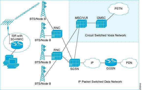
The GSM-based network, shown in Figure 2-1, uses the Base Transceiver Station (BTS) at the cell tower, known as the Node-B in UMTS. The 3G-HWIC-based ISR communicates with Node-B over the air and attaches itself to the network before setting up a data session (known as PDP context) with the network. The Node-B terminates the radio network access technology. The Radio Network Controller (RNC) provides mobility service to mobiles served by the attached Node-Bs.
To support broadband IP data network capability, two network node types are introduced: SGSN and GGSN. SGSN performs mobility function to replace the Visitor Location Register (VLR) functionality. GGSN acts as an IP packet gateway to the Internet. The broadband IP data packet path takes place from the mobile node (handset) to the Node-B, RNC, SGSN, GGSN, and to the Internet. The traditional circuit-switched path continues via the MSC, GMSC, and PSTN. The broadband IP data network acts as an overlay network over the existing cellular network. The 2.5G network is the original GPRS network, with the same physical topology, as shown in Figure 2-1.
Figure 2-1 GSM 3G IP Wireless Data Network
2.5/3G GSM Data Call Establishment
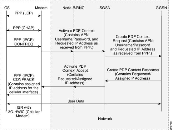
Figure 2-2 shows 3G data calls in the GSM network. The PPP terminates between the IOS and the modem in the 3G-HWIC. Over-the-air PPP is not used; instead, 3GPP-defined protocol is used to set up the call. The 3GPP-defined protocol terminates on the modem on one end and the SGSN/GGSN on the other end.
Before the very first call can be set up, you must get a data service account from your service provider. As a part of this service, a SIM card is provided by the service provider. The SIM card must be installed on the 3G-HWIC.
•![]() PPP CHAP User-Name (hostname)
PPP CHAP User-Name (hostname)
•![]() PPP CHAP Password
PPP CHAP Password
•![]() APN (Access Point Name)
APN (Access Point Name)
You can create a profile in the modem, as shown in Example 2-1. The profile stores these parameters in the NVRAM of the modem. This allows the modem to authenticate the IOS at the PPP CHAP phase so that the IOS can continue on to the next phase PPP IPCP without having to wait for the real authentication that actually takes place with the wireless network over the air.
The very first packet that meets the interesting traffic criteria, as defined by the associated ACLs, causes the dial out to occur via the cellular interface. This causes PPP LCP and PPP CHAP to complete between the IOS and the modem. The modem stores the PPP user-name (hostname) and password, which allows the CHAP to succeed locally, and the IPCP phase can start immediately.
As part of the PPP IPCP phase, the IOS sends the CONFREQ message, requesting the IP address for the cellular interface (and possibly the DNS addresses, if configured for these addresses). After the modem receives the CONFREQ, it sends the Activate PDP Context Request message over the air. This message contains the Username, Password, and the APN stored in the NVRAM, which was created as part of the profile. The message requests the IP address for the cellular message and DNS IP addresses, if applicable.
The SGSN, upon receipt of Activate PDP Context Request message, sends the Create PDP Context Request message, relaying these parameters to the appropriate GGSN. The GGSN validates the user, assigns an IP address to the cellular interface, and returns this in the Create PDP Context Response message to the SGSN. This information is relayed to the modem, by the SGSN, as an Activate PDP Context Accept message.
Finally, the modem returns the pending IPCP response to the IOS (CONFACK), returning the IP address, and any other requested information, such as DNS addresses. The IP address is bound to the cellular interface and installed in the routing table. Now the user data transfer can begin.
Figure 2-2 GSM 3G Data Call Establishment Call Flow
GSM Modem Profile Creation and Preparation for Network Connectivity
A newly installed 3G GSM wireless HWIC must complete a series of steps before it can connect to the wireless network. These steps are described in the following sections.
Service Plans
The 3G HWIC needs to be associated with a service plan before it can be activated on a carrier network. Depending on the mobile operator, there are multiple mobile broadband data plans available: unlimited, metered, or pooled. It may be possible to tie the 3G HWIC service to an existing enterprise wireless contract, which helps to keep down the monthly recurring cost (MRC).
The link below lists the mobile operators that have certified the 3G HWIC and provides links to these carrier websites for additional information on the service.
Selection of best radio network
If HSDPA is available, the 3G HWIC will downshift to the best radio network available, down to 2.5G technology. This means the 3G HWIC will attempt to connect to the best network available on the operator's network. If HSDPA is not available, the 3G HWIC will negotiate for UMTS, and if that is not available, it will negotiate for the 2.5G technology EDGE, and then GPRS.
Modem Profile Creation
Create a GSM data connectivity profile in the cellular modem before attempting to set up a data connection with the cellular network. This profile defines the user and its set of authentication parameters with the modem and the cellular network.
The cellular x/x/x gsm profile create command is used for creating a GSM profile, which will be used for dialing out using PPP to establish a data connection (PPP connection/PDP context) with the 3G cellular modem and the cellular data network.
Example 2-1 Creating a Modem Profile
Router# cellular x/x/x gsm profile create profile-number APN {chap | pap}
chap-or-pap-user-name chap-or-pap-password
The following is a sample output of the cellular x/x/x gsm profile create command:
Router# cellular 0/0/0 gsm profile create 12 xyz.com chap userXyz passwordForXyz
Profile 12 will be created with the following values:
APN = xyz.com
Authenticaton = CHAP
Username = userXyz
Password = passwordForXyz
Are you sure? [confirm]
Profile 12 written to modem
Router#
Router# sh cellular 0/0/0 profile 12
Load for five secs: 1%/0%; one minute: 1%; five minutes: 1%
Time source is hardware calendar, *18:09:14.944 UTC Tue Jun 26 2007
Profile 12 = INACTIVE
--------
PDP Type = IPv4
Access Point Name (APN) = xyz.com
Authentication = CHAP
Username: userXyz, Password: passwordForXyz
Router#
Preparation for Network Connectivity
When the 3G HWIC first dials the mobile network after activation, it can take 2 to 5 seconds to establish end-to-end radio and IP connectivity. If the modem needs to redial, it can take longer than 5 seconds. In addition, the first time the modem is activated on the network, there are provisioning processes that kick off in the background that will cause the initial end-to-end connectivity to take longer.
Follow the steps below to prepare for network connectivity.
Step 1 ![]() Ensure that the SIM card obtained from your service provider is correctly placed on the 3G HWIC.
Ensure that the SIM card obtained from your service provider is correctly placed on the 3G HWIC.
Step 2 ![]() Connect the antenna to the HWIC.
Connect the antenna to the HWIC.
Step 3 ![]() Ensure that the RSSI signal level is better than -90 dBm.
Ensure that the RSSI signal level is better than -90 dBm.
Step 4 ![]() Run show cellular x/x/x all command to verify connectivity to the network.
Run show cellular x/x/x all command to verify connectivity to the network.
The following is a sample output of the show cellular x/x/x all command.
Example 2-2 Checking Network Connectivity
The blue italicized text throughout this configuration is used to indicate comments and will not be seen when a normal console output is viewed. The bold text is used to indicate important commands to refer back to in case of an error. When debugging, ensure that all the commands in bold are the same in your console output.
Router# show cellular 0/0/0 all
!
Only relevant information is shown; the rest is deleted for readability purposes.
!
Profile Information
====================
Profile 1 = INACTIVE*
--------
PDP Type = IPv4
Access Point Name (APN) = xyz.com
Authentication = CHAP
Username: userXyz, Password: passwordForXyz
* - Default profile
!
Ensure that your created profile is as expected, without any typographical errors, or any
inadvertent white space(s).
!
Data Connection Information
===========================
Profile 12, Packet Session Status = INACTIVE
Inactivity Reason = Unknown
Network Information
===================
Current Service Status = Normal, Service Error = None
Current Service = Combined
Packet Service = UMTS/WCDMA (Attached)
Packet Session Status = Inactive
Current Roaming Status = Roaming
Network Selection Mode = Automatic
Country = USA, Network = GSM
Mobile Country Code (MCC) = 310
Mobile Network Code (MNC) = 380
Location Area Code (LAC) = 56997
Routing Area Code (RAC) = 253
Cell ID = 5931
Primary Scrambling Code = 184
PLMN Selection = Automatic
Registered PLMN = GSM, Abbreviated =
Service Provider =
!
This particular example shows the network Packet Service is 'UMTS/WCDMA', and is
'Attached'. Your service may be somewhat different depending on service(s) provided by
your service provider.
Current Service Status should indicate 'Normal', as shown.
!
Radio Information
=================
Current Band = WCDMA 1900, Channel Number = 9721
Current RSSI(RSCP) = -87 dBm
!
RSSI signal level should be better than -90 dBm, although data service may operate at
levels below these.
!
Modem Security Information
==========================
Card Holder Verification (CHV1) = Disabled
SIM Status = OK
SIM User Operation Required = None
Number of Retries remaining = 3
!
The SIM card is properly recognized.
!
Step 5 ![]() Configure the router as described in "Advanced Network Deployment Scenarios" section.
Configure the router as described in "Advanced Network Deployment Scenarios" section.
Step 6 ![]() Depending on your deployment requirement, connect to the network via the appropriate protocol and verify data transfer.
Depending on your deployment requirement, connect to the network via the appropriate protocol and verify data transfer.
For more information, see:
http://www.cisco.com/en/US/docs/routers/access/1800/1861/software/feature/guide/mrwlsgsm.html
 Feedback