- Preface
- Overview of the Cisco 7600 Series Ethernet Services 20G Line Card
- Configuring the Cisco 7600 Series Ethernet Services 20G Line Card
- Configuring QoS on the Cisco 7600 Series Ethernet Services 20G Line Card
- Command Summary for the Cisco 7600 Series Ethernet Services 20G Line Card
- Troubleshooting the Cisco 7600 Series Ethernet Services 20G Line Card
- Required Configuration Tasks
- Identifying Slots and Subslots for the Cisco 7600 Series Ethernet Services 20G Line Card
- Configuring High-Availability Features
- Failover Operations
- Restrictions for PMLACP
- Configuring PMLACP on Cisco 7600
- Troubleshooting Tips
- Configuring Custom Ethertype for EVC Interfaces
- Configuring Flexible QinQ Mapping and Service Awareness on 7600-ESM-2X10GE and 7600-ESM-20X1GE
- Configuring Flexible Service Mapping Based on CoS and Ethertype
- Configuring MultiPoint Bridging over Ethernet on 7600-ESM-2X10GE and 7600-ESM-20X1GE
- Configuring Gigabit Ethernet Link Aggregation with Advanced Load Balancing
- Configuring Virtual Private LAN Service (VPLS) with Port-Channel as a Core Interface
- Configuring the Backup Interface for Flexible UNI
- Configuring Layer2 Access Control Lists (ACLs) on an EVC
- Configuring Broadcast Storm Control on Switchports and Ports with Ethernet Virtual Connections
- Traffic Storm Control on ES20 Switchports
- Traffic Storm Control on ES20 with EVCs
- Configuring Asymmetric Carrier-Delay
- Configuring MST on EVC Bridge Domain
- DHCP Snooping with Option-82 on EVC
- Configuring MAC Address Security for EVC Bridge-Domain
- Restrictions and Usage Guidelines
- Configuring MAC Address Security for EVC Bridge-Domain
- Enabling MAC Address Security for EVC Bridge-Domain
- Disabling MAC Address Security for EVC Bridge-Domains on an EFP
- Configuring Whitelisted MAC Address on an EFP
- Configuring Sticky MAC Addresses on an EFP
- Configuring Secure MAC Address Aging on an EFP
- Configuring MAC Address Limiting on an EFP
- Configuring MAC Address Limiting on a Bridge-Domain
- Configuring Violation Response on an EFP
- Troubleshooting
- Configuring Static MAC on Ethernet Flow Point and Pseudowire
- Restrictions and Usage Guidelines
- Configuring Resilient Ethernet Protocol
- REP Edge No-Neighbor
- Configuring REP over Ethernet Virtual Circuit
- Restrictions and Usage Guidelines
- Configuring REP over EVC for the Cisco 7600 Router
- Configuring REP over EVC using Cross connect for the Cisco 7600 Router
- Configuring REP over EVC using connect for the Cisco 7600 Router
- Configuring REP over EVC using bridge domain for the Cisco 7600 Router
- Configuring Resilient Ethernet Protocol Configurable Timers
- Restrictions and Usage Guidelines
- Configuring REP Configurable Timers for the Cisco 7600 Router
- Configuring the REP Link Status Layer Retries
- Configuring the REP Link Status Layer Age Out Timer
- Configuring the REP Link Status Layer Age Out Timer
- Troubleshooting
- Configuring CFM over EFP Interface with cross connect
- Restrictions and Usage Guidelines
- Configuring CFM over EFP with xconnect for the Cisco 7600 Router
- Configuring CFM over EFP Interface with Cross Connect—Basic Configuration
- Configuring CFM over EFP Interface with Cross Connect—Single Tag VLAN Cross Connect
- Configuring CFM over EFP Interface with Cross Connect—Double Tag VLAN Cross Connect
- Configuring CFM over EFP Interface with Cross Connect—Selective QinQ Cross Connect
- Configuring CFM over EFP Interface with Cross Connect—Port-Based Cross Connect Tunnel
- Configuring CFM over EFP Interface with Cross Connect—Port Channel-Based Cross Connect Tunnel
- Troubleshooting CFM Features
- Configuring Reverse Layer 2 Gateway Ports for the Cisco 7600 Router
- Configuring Private Host Switch Virtual Interface (VLAN and VPLS)
Configuring the Cisco 7600 Series Ethernet Services 20G Line Card
This chapter provides information about configuring the Cisco 7600 Series Ethernet Services 20G (ES20) line card on the Cisco 7600 series router. It includes the following sections:
•![]() Configuring High-Availability Features
Configuring High-Availability Features
•![]() Configuring UDE on ES20 Line Cards
Configuring UDE on ES20 Line Cards
•![]() Configuring Unidirectional Link Detection (UDLD) on Ports with EVCs
Configuring Unidirectional Link Detection (UDLD) on Ports with EVCs
•![]() Configuring IEEE 802.1ag-2007 Compliant CFM
Configuring IEEE 802.1ag-2007 Compliant CFM
•![]() Multichassis Support for Link Aggregation Control Protocol
Multichassis Support for Link Aggregation Control Protocol
•![]() Pseudo MLACP Support on Cisco 7600
Pseudo MLACP Support on Cisco 7600
•![]() Configuring Flexible QinQ Mapping and Service Awareness on 7600-ESM-2X10GE and 7600-ESM-20X1GE
Configuring Flexible QinQ Mapping and Service Awareness on 7600-ESM-2X10GE and 7600-ESM-20X1GE
•![]() Configuring Flexible Service Mapping Based on CoS and Ethertype
Configuring Flexible Service Mapping Based on CoS and Ethertype
•![]() Configuring MultiPoint Bridging over Ethernet on 7600-ESM-2X10GE and 7600-ESM-20X1GE
Configuring MultiPoint Bridging over Ethernet on 7600-ESM-2X10GE and 7600-ESM-20X1GE
•![]() Configuring Gigabit Ethernet Link Aggregation with Advanced Load Balancing
Configuring Gigabit Ethernet Link Aggregation with Advanced Load Balancing
•![]() Configuring Virtual Private LAN Service (VPLS) with Port-Channel as a Core Interface
Configuring Virtual Private LAN Service (VPLS) with Port-Channel as a Core Interface
•![]() Configuring the Backup Interface for Flexible UNI
Configuring the Backup Interface for Flexible UNI
•![]() Configuring Broadcast Storm Control on Switchports and Ports with Ethernet Virtual Connections
Configuring Broadcast Storm Control on Switchports and Ports with Ethernet Virtual Connections
•![]() Traffic Storm Control on ES20 Switchports
Traffic Storm Control on ES20 Switchports
•![]() Traffic Storm Control on ES20 with EVCs
Traffic Storm Control on ES20 with EVCs
•![]() Configuring Asymmetric Carrier-Delay
Configuring Asymmetric Carrier-Delay
•![]() Configuring MST on EVC Bridge Domain
Configuring MST on EVC Bridge Domain
•![]() DHCP Snooping with Option-82 on EVC
DHCP Snooping with Option-82 on EVC
•![]() Configuring MAC Address Security for EVC Bridge-Domain
Configuring MAC Address Security for EVC Bridge-Domain
•![]() Configuring Static MAC on Ethernet Flow Point and Pseudowire
Configuring Static MAC on Ethernet Flow Point and Pseudowire
•![]() Configuring Resilient Ethernet Protocol
Configuring Resilient Ethernet Protocol
•![]() Configuring CFM over EFP Interface with cross connect
Configuring CFM over EFP Interface with cross connect
•![]() Configuring Reverse Layer 2 Gateway Ports for the Cisco 7600 Router
Configuring Reverse Layer 2 Gateway Ports for the Cisco 7600 Router
•![]() Configuring Private Host Switch Virtual Interface (VLAN and VPLS)
Configuring Private Host Switch Virtual Interface (VLAN and VPLS)
•![]() Configuring Multicast Features
Configuring Multicast Features
•![]() Configuring IGMP/PIM Snooping for VPLS Pseudowire on 7600-ESM-2X10GE and 7600-ESM-20X1GE
Configuring IGMP/PIM Snooping for VPLS Pseudowire on 7600-ESM-2X10GE and 7600-ESM-20X1GE
•![]() Configuring Link State Tracking (LST)
Configuring Link State Tracking (LST)
•![]() Configuring Multicast VLAN Registration
Configuring Multicast VLAN Registration
•![]() Configuring Layer 3 and Layer 4 Features
Configuring Layer 3 and Layer 4 Features
•![]() Configuring Layer 3 and Layer 4 Access Control List on a Service Instance
Configuring Layer 3 and Layer 4 Access Control List on a Service Instance
•![]() Configuring Any Transport over MPLS
Configuring Any Transport over MPLS
•![]() Configuring MPLS Traffic Engineering Class-Based Tunnel Selection
Configuring MPLS Traffic Engineering Class-Based Tunnel Selection
•![]() Configuring Virtual Private LAN Service
Configuring Virtual Private LAN Service
•![]() Configuring SVI-Based IP/Routed Interworking
Configuring SVI-Based IP/Routed Interworking
•![]() Resetting a Cisco 7600 Series Ethernet Services 20G Line Card
Resetting a Cisco 7600 Series Ethernet Services 20G Line Card
For information about managing your system images and configuration files, refer to the Cisco IOS Configuration Fundamentals Configuration Guide and Cisco IOS Configuration Fundamentals Command Reference publications that correspond to your Cisco IOS software release.
For more information about some of the commands used in this chapter, see
Chapter A, "Command Summary for the Cisco 7600 Series Ethernet Services 20G Line Card," and the Cisco IOS Release 12.2 SR Command References at http://www.cisco.com/en/US/products/ps6922/prod_command_reference_list.html
Also refer to the related Cisco IOS software command reference and master index publications. For more information about accessing these publications, see the "Related Documentation" section.
Required Configuration Tasks
As of Cisco IOS Release 12.2SRB, there are not many features that require direct configuration on the ES20 line card. You do not need to attach to the ES20 line card itself to perform any configuration.
Identifying Slots and Subslots for the Cisco 7600 Series Ethernet Services 20G Line Card
The ES20 line card supports In-Service Software Upgrade (ISSU) with Enhanced Fast Software Upgrade (eFSU). ISSU allows for the upgrade and downgrade of Cisco IOS images at different release levels on the active and standby supervisors. ISSU procedure also applies to upgrade and downgrade of line card images. A new line card image is loaded, as necessary, when the supervisor engine software is upgraded or downgraded.
For more information, see the Cisco 7600 Series Cisco IOS Software Configuration Guide, 12.2SR at http://www.cisco.com/en/US/docs/routers/7600/ios/12.2SR/configuration/guide/swcg.html
Configuring High-Availability Features
This section provides information about configuring high-availability features specific to the ES20 line card.
Configuring UDE on ES20 Line Cards
Unidirectional Ethernet (UDE) feature allows interfaces to operate as unidirectional links, that is, either in receive (Rx) only mode or transmit (Tx) only mode. Unidirectional Ethernet uses only one strand of fiber for either transmitting or receiving one-way traffic for Gig Ports instead of two strands of fiber for a full duplex operation.
UDLR mechanism allows a set of feeds and receivers, which are directly connected by a unidirectional link, to send datagrams as if they were all connected by a bidirectional link.
Unidirectional Routing is used in applications with a great amount of data traffic flowing in one direction and little control traffic flowing in the opposite direction.
When an interface is configured as unidirectional send-only or receive-only, the following actions take place:
•![]() For ports configured as send-only, the port ONLY transmits data and ignores any received data. Similarly receive-only ports do not transmit data.
For ports configured as send-only, the port ONLY transmits data and ignores any received data. Similarly receive-only ports do not transmit data.
•![]() UDLD is automatically disabled on the interface.
UDLD is automatically disabled on the interface.
•![]() Autonegotiation is disabled on the interface.
Autonegotiation is disabled on the interface.
Restrictions and Usage Guidelines
The following restrictions apply to the UDE links on ES20 line cards:
•![]() Uni Directional Link Routing (UDLR) is configured only on routed ports. Configure the IPv4 address on the UDLR tunnel. Each UDE can either be a switched port or a routed port and has a separate UDLR tunnel. UDLR handles bidirectional communication over the back channel.
Uni Directional Link Routing (UDLR) is configured only on routed ports. Configure the IPv4 address on the UDLR tunnel. Each UDE can either be a switched port or a routed port and has a separate UDLR tunnel. UDLR handles bidirectional communication over the back channel.
•![]() Configuring unidirectional links may cause STP Loops. You must configure protocols correctly to avoid problems with the network.
Configuring unidirectional links may cause STP Loops. You must configure protocols correctly to avoid problems with the network.
•![]() For unidirectional links, you should manually configure the encapsulation and trunk mode to fixed values on each side. The protocol is not aware of the link type and will continue to try and negotiate if it is configured to do so. If both sides of a unidirectional link are negotiating, it is possible to get a trunk mismatch where the receive-only side becomes a trunk while the send-only side is access.
For unidirectional links, you should manually configure the encapsulation and trunk mode to fixed values on each side. The protocol is not aware of the link type and will continue to try and negotiate if it is configured to do so. If both sides of a unidirectional link are negotiating, it is possible to get a trunk mismatch where the receive-only side becomes a trunk while the send-only side is access.
•![]() For send-only unidirectional links, switches cannot receive any CDP information about neighbors and VLAN mismatches cannot be detected.
For send-only unidirectional links, switches cannot receive any CDP information about neighbors and VLAN mismatches cannot be detected.
•![]() VTP will not work if the VTP server is downstream of the unidirectional link. VTP pruning on send-only unidirectional links should preferably be disabled.
VTP will not work if the VTP server is downstream of the unidirectional link. VTP pruning on send-only unidirectional links should preferably be disabled.
•![]() Dot1x is incompatible with ULDR.
Dot1x is incompatible with ULDR.
•![]() If the link between a switch and a host is made unidirectional, IGMP snooping will not work because either the host will not receive IGMP queries from the switch or the switch will not receive IGMP reports from the host.
If the link between a switch and a host is made unidirectional, IGMP snooping will not work because either the host will not receive IGMP queries from the switch or the switch will not receive IGMP reports from the host.
•![]() If two network devices are connected by a unidirectional link, then ARP requests and the response mechanism will not work. Additionally, static entries need to be created for proper functionality of protocols depending on such a mechanism.
If two network devices are connected by a unidirectional link, then ARP requests and the response mechanism will not work. Additionally, static entries need to be created for proper functionality of protocols depending on such a mechanism.
•![]() Link Detection does not work on unidirectional interfaces.
Link Detection does not work on unidirectional interfaces.
•![]() Unidirectional Ethernet with EtherChannel configuration is not supported on ES20 line cards.
Unidirectional Ethernet with EtherChannel configuration is not supported on ES20 line cards.
•![]() Receive-only transceivers are not supported.
Receive-only transceivers are not supported.
•![]() UDE is only supported on a single fiber .
UDE is only supported on a single fiber .
•![]() ISIS does not work with UDE/UDLR.
ISIS does not work with UDE/UDLR.
•![]() Auto-rp discovery packets are not received on the UDE receive-only port if UDE is configured with SVI. UDE links configured on routed ports do not have this issue.
Auto-rp discovery packets are not received on the UDE receive-only port if UDE is configured with SVI. UDE links configured on routed ports do not have this issue.
•![]() The loopback mac command should not be configured explicitly when UDE is configured on an ES20 port. Similarly UDE should not be configured if loopback mac is configured on an ES20 port.
The loopback mac command should not be configured explicitly when UDE is configured on an ES20 port. Similarly UDE should not be configured if loopback mac is configured on an ES20 port.
SUMMARY STEPS
1. ![]() enable
enable
2. ![]() configure terminal
configure terminal
3. ![]() interface
interface
4. ![]() unidrectional {send-only | receive-only}
unidrectional {send-only | receive-only}
5. ![]() ip-address ip_address mask
ip-address ip_address mask
DETAILED STEPS
Examples
Router A Configuration
In this example, interface 10.1.0.1 on Router A is configured as the send-only port while the tunnel running from 11.0.0.1 to 11.0.0.2 is configured as the receive-only interface.
interface tengigabitethernet 1/0/0
unidirectional send-only
ip address 10.1.0.1 255.255.0.0
ip pim sparse-dense-mode
!
! Configure tunnel as receive-only UDLR tunnel!
interfacetunnel 0
tunnel source 11.0.0.1
tunnel destination 11.0.0.2
tunnel udlr receive-only tengigabitethernet 1/0/0
Router B Configuration
In this example, interface 10.1.0.2 on Router B is configured as the receive-only port while the tunnel running from 11.0.0.2 to 11.0.0.1 is configured as the receive-only interface.
Config e.g 1
interface tengigabitethernet 1/0/0
unidirectional receive-only
ip address 10.1.0.2 255.255.0.0
ip pim sparse-dense-mode
!
! Configure tunnel as send-only UDLR tunnel.
!
interface tunnel 0
tunnel source 11.0.0.2
tunnel destination 11.0.0.1
tunnel udlr send-only tengigabitethernet 1/2
tunnel udlr address-resolution
Config e.g 2
interface GigabitEthernet1/0/0
switchport
switchport access vlan 100
switchport mode access
no ip address
speed nonegotiate
unidirectional send-only
interface Vlan100
ip address 10.0.1.1 255.255.255.0
ip pim sparse-mode
Switched Port UDE Configuration
This example shows UDE configuration on a switched port with an SVI interface, with OSPF enabled.
Topology :
[UDE-R1]-----UDE--------->[UDE-R2]
<-------UDLR-------
UDE-R1#sh run int gig2/0/5
Building configuration...
Current configuration : 165 bytes
!
interface GigabitEthernet2/0/5
switchport
switchport access vlan 300
switchport mode access
speed nonegotiate
no mls qos trust
unidirectional send-only
end
UDE-R1#sh run int tunnel 10
Building configuration...
Current configuration : 150 bytes
!
interface Tunnel10
ip address 70.10.10.1 255.255.255.0
tunnel source 50.0.0.1
tunnel destination 50.0.0.2
tunnel udlr receive-only Vlan300
end
UDE-R1#sh run int vlan 300
Building configuration...
Current configuration : 104 bytes
!
interface Vlan300
ip address 90.90.90.99 255.255.255.0
end
router ospf 1
log-adjacency-changes
network 20.0.0.0 0.0.0.255 area 0
network 90.90.90.0 0.0.0.255 area 0
############ config on R2####################
UDE-R2#sh run int gig2/0/1
Building configuration...
Current configuration : 170 bytes
!
interface GigabitEthernet2/0/1
switchport
switchport access vlan 300
switchport mode access
speed nonegotiate
mls qos trust dscp
unidirectional receive-only
end
UDE-R2#sh run int tunnel 10
Building configuration...
Current configuration : 179 bytes
!
interface Tunnel10
ip address 70.10.10.2 255.255.255.0
tunnel source 50.0.0.2
tunnel destination 50.0.0.1
tunnel udlr send-only Vlan300
tunnel udlr address-resolution
end
UDE-R2#sh run int vlan 300
Building configuration...
Current configuration : 82 bytes
!
interface Vlan300
ip address 90.90.90.90 255.255.255.0
end
router ospf 1
log-adjacency-changes
network 30.0.0.0 0.0.0.255 area 0
network 90.90.90.0 0.0.0.255 area 0
Verification
Use the following commands to verify operation.
Configuring Unidirectional Link Detection (UDLD) on Ports with EVCs
UDLD (Unidirectional Link Detection) is a Layer 2 protocol that interacts with a Layer 1 protocol to determine the physical status of a link. At Layer 1, physical signaling and fault detection is auto-negotiated. UDLD detects the neighbor link, identifies, and disables the wrongly connected LAN ports. When you enable auto-negotiation and UDLD, Layer 1 and Layer 2 detections prevent physical and logical unidirectional connections, and malfunctioning of other protocols.
A unidirectional link occurs when the neighbor link receives the traffic transmitted by the local device, but the local device does not receive the transmitted traffic from its neighbor. If auto-negotiation is active, and one of the fiber strands in a pair is disconnected, the link is disabled. The logical link is undetermined, and UDLD does not take any action. At Layer 1, if both fibers are normal, UDLD at Layer 2 determines if the fibers are accurately connected, and traffic is relayed bidirectionally between the right neighbors. In this scenario, auto-negotiation operates in Layer 1, and the link status is unchecked.
The UDLD protocol monitors physical configuration of the cables, and detects unidirectional links of devices connected to LAN ports via Ethernet cables. When a unidirectional link is detected, UDLD disables the affected LAN port, and alerts the user.
The Cisco 7600 series router periodically transmits UDLD packets to neighboring devices on LAN ports with UDLD. If the packets are returned within a specific time frame, and there is no acknowledgement, the link is flagged as unidirectional, and the LAN port is disabled.
Restrictions and Usage Guidelines
Follow these restrictions and usage guidelines while configuring UDLD on ports with EVCs:
•![]() You can configure UDLD only on a port.
You can configure UDLD only on a port.
•![]() To identify and disable the unidirectional links, devices at both ends must support UDLD.
To identify and disable the unidirectional links, devices at both ends must support UDLD.
•![]() Service bridge domain should be available on the router.
Service bridge domain should be available on the router.
•![]() Any of the supported EVC encapsulation can be configured.
Any of the supported EVC encapsulation can be configured.
•![]() Cisco IOS Release 15.1(1)S supports EVC port-channels.
Cisco IOS Release 15.1(1)S supports EVC port-channels.

Note ![]() If UDLD is enabled on an EVC port with service type connect or xconnect and encapsulation type default or untagged, the port is disabled.
If UDLD is enabled on an EVC port with service type connect or xconnect and encapsulation type default or untagged, the port is disabled.
For more information on UDLD, see the Cisco 7600 Series Cisco IOS Software Configuration Guide, 12.2SR at the following URL:
http://www.cisco.com/en/US/docs/routers/7600/ios/12.2SR/configuration/guide/udld.html
Configuring UDLD Aggressive Mode
As UDLD aggressive mode is disabled by default, you can configure UDLD aggressive mode in point-to-point links between network devices that support UDLD aggressive mode.
When UDLD aggressive mode is enabled:
•![]() A port on a bidirectional link with UDLD neighbor relationship does not receive UDLD packets.
A port on a bidirectional link with UDLD neighbor relationship does not receive UDLD packets.
•![]() UDLD tries to reestablish the connection with the neighbor.
UDLD tries to reestablish the connection with the neighbor.
•![]() After eight failed retries, the port is disabled.
After eight failed retries, the port is disabled.
To prevent spanning tree loops, ensure that you set the non aggressive UDLD value interval to 15 seconds. This disables the unidirectional link before blocking the port transitions in the forwarding state (with default spanning tree parameters).
The benefits of enabling UDLD aggressive mode are:
•![]() Port on one side of a link is disabled (both Tx and Rx).
Port on one side of a link is disabled (both Tx and Rx).
•![]() One side of a link is enabled even if the other side of the link fails.
One side of a link is enabled even if the other side of the link fails.
In the above scenario, UDLD aggressive mode disables the port that prevents traffic from being discarded.
Enabling UDLD on Ports With EVC Configured
SUMMARY STEPS
1. ![]() enable
enable
2. ![]() configure terminal
configure terminal
3. ![]() {udld | no udld} enable aggressive
{udld | no udld} enable aggressive
4. ![]() exit
exit
DETAILED STEPS
SUMMARY STEPS
1. ![]() interface type/ slot/ port
interface type/ slot/ port
2. ![]() {udld port | no udld port } aggressive
{udld port | no udld port } aggressive
3. ![]() show udld type/ slot/ port
show udld type/ slot/ port
4. ![]() exit
exit
DETAILED STEPS
Disabling Individual UDLD on Ports With EVC Configured
SUMMARY STEPS
1. ![]() interface type/ slot/ port
interface type/ slot/ port
2. ![]() {udld port | no udld port } disable
{udld port | no udld port } disable
3. ![]() show udld type/ slot/ port
show udld type/ slot/ port
4. ![]() exit
exit
DETAILED STEPS
Resetting Disabled UDLD on Ports With EVC Configured
SUMMARY STEPS
1. ![]() udld reset
udld reset
DETAILED STEPS
|
|
|
|
|---|---|---|
Step 1 |
udld reset Router# udld reset |
Resets all the LAN ports disabled by UDLD. |
Example
This example displays the global configuration values at router 1:
Router(config)#udld enable
This example displays the ESM20 port at router 1:
Router(config)# inter gi 2/0/1
Router(config-if)# udld port aggressive
Router(config-if)# service instance 1 ethernet
Router(config-if-srv)# encapsulation dot1q 100
Router(config-if-srv)# rewrite ingess tag translate 1-to2 dot1q 5 second-dot1q 5 symmetric
Router(config-if-srv)# bridge-domain 100
This example displays the configuration for a port that is part of a port channel:
Router(config)#interface Port-channel1
Router(config-if)#no ip address
Router(config-if)#service instance 1 ethernet
Router(config-if)#encapsulation untagged
Router(config-if)#bridge-domain 100
Router(config)#interface GigabitEthernet3/0/13
Router(config-if)#ip arp inspection limit none
Router(config-if)#no ip address
Router(config-if)#udld port aggressive
Router(config-if)#no mls qos trust
Router(config-if)#channel-group 1 mode on
Verification
Use the show udld and show udld interface commands to verify the UDLD configuration:
Router(config)show udld gi 3/0/13
Interface Gi1/3
---Port enable administrative configuration setting: Enabled / in aggressive mode
Port enable operational state: Enabled / in aggressive mode
Current bidirectional state: Bidirectional
Current operational state: Advertisement - Single neighbor detected
Message interval: 15
Time out interval: 5
Entry 1
---
Expiration time: 37
Cache Device index: 1
Current neighbor state: Bidirectional
Device ID: 011932118C0
Port ID: Gi1/1
Neighbor echo 1 device: 0FF71CA880
Neighbor echo 1 port: Gi1/3
Message interval: 15
Time out interval: 5
CDP Device name: rish2
ISSU Support for ES20 Line Card
The ES20 line card supports In-Service Software Upgrade (ISSU) with Enhanced Fast Software Upgrade (eFSU). ISSU allows for the upgrade and downgrade of Cisco IOS images at different release levels on the active and standby supervisors. ISSU procedure also applies to upgrade and downgrade of line card images. A new line card image is loaded, as necessary, when the supervisor engine software is upgraded or downgraded.
Configuring IEEE 802.1ag-2007 Compliant CFM
A Metro Ethernet network consists of networks from multiple operators supported by one service provider and connects multiple customer sites to form a virtual private network (VPN). Networks provided and managed by multiple independent service providers have restricted access to each other's equipment. Because of the diversity in these multiple-operator networks, failures must be isolated quickly. As a Layer 2 network, Ethernet must be capable of reporting network faults at Layer 2.
IEEE 802.3ah is a point-to-point and per- physical- wire OAM protocol that detects and isolates connectivity failures in the network. IEEE 802.1ag draft 8.1 Metro Ethernet Connectivity Fault Management (CFM) incorporates several OAM facilities that allow you to manage Metro Ethernet networks, including an Ethernet continuity check, end-to-end Ethernet traceroute facility using Linktrace message (LTM), Linktrace reply (LTR), Ethernet ping facility using Loopback Message (LBM), and a Loopback Reply (LBR). These Metro Ethernet CFM protocol elements quickly identify problems in the network.
Ethernet Connectivity Fault Management (CFM) is an end-to-end per-service-instance Ethernet layer operations, administration, and maintenance (OAM) protocol. It includes proactive connectivity monitoring, fault verification, and fault isolation for large Ethernet metropolitan-area networks (MANs) and WANs. Connectivity Fault Management (CFM) is the indispensable capability that service providers require to deploy large-scale, multivendor Metro Ethernet services. This feature upgrades the implementation of CFM to be compliant with the IEEE 802.1ag with the current standard, 802.1ag-2007 and implementation of CFM over L2VFI (Layer 2 Virtual Forwarding Instance Information), cross connect, EVC, and Switchport.
Key CFM mechanisms are:
•![]() Maintenance domains (MDs) that break up the responsibilities for the network administration of a given end-to-end service.
Maintenance domains (MDs) that break up the responsibilities for the network administration of a given end-to-end service.
•![]() Maintenance associations (MAs) that monitor service instances within a specified MD.
Maintenance associations (MAs) that monitor service instances within a specified MD.
•![]() Maintenance points, (MPs or MIPs), such as Maintenance end points (MEP's) that transmit and receive CFM protocol messages, and MIPs that catalog information received from MEPs, and respond to Linktrace and Loopback messages.
Maintenance points, (MPs or MIPs), such as Maintenance end points (MEP's) that transmit and receive CFM protocol messages, and MIPs that catalog information received from MEPs, and respond to Linktrace and Loopback messages.
•![]() Protocols (Continuity Check, Loopback, and Linktrace) that are used to manage faults.
Protocols (Continuity Check, Loopback, and Linktrace) that are used to manage faults.
For more information on CFM, see Cisco IOS Carrier Ethernet Configuration Guide, Release 12.2SR at
http://www.cisco.com/en/US/docs/ios-xml/ios/cether/configuration/12-2sr/ce-12-2sr-book.html
For more information about the commands used in this section, see Cisco IOS Ethernet Command Reference Guide at http://www.cisco.com/en/US/docs/ios/cether/command/reference/ce_book.html
Supported Line Cards
Use the ethernet cfm global command to enable the CFM D8.1 feature on the following line cards:
•![]() ES20 and ES40:Switchports, routed ports, and EVC BD.
ES20 and ES40:Switchports, routed ports, and EVC BD.
•![]() SIP400:Routed ports, and Layer 2 Virtual Forwarding Instance ( L2VFI).
SIP400:Routed ports, and Layer 2 Virtual Forwarding Instance ( L2VFI).
•![]() SIP600:Switchports, and routed ports.
SIP600:Switchports, and routed ports.
•![]() 67xx: Switchports, and routed ports.
67xx: Switchports, and routed ports.
The complete support matrix for the CFM D8.1 feature is given in Table 2-1and Table 2-2.
Note ![]() Table 2-1 and Table 2-2 are part of the same table. The table is split into two for better readability.
Table 2-1 and Table 2-2 are part of the same table. The table is split into two for better readability.
Table 2-1 Supported Matrix1
Table 2-2 Supported Matrix 2
Scalable Limits
Table 2-3 maps the supported interfaces with the CFM points and their scalability values:
Table 2-3
Scalable Limits
Restrictions and Usage Guidelines
When configuring CFM D8.1, follow these restrictions and usage guidelines:
•![]() Hardware EoMPLS is not supported.
Hardware EoMPLS is not supported.
•![]() Supports interworking between routed ports, switch ports, and EVC BD.
Supports interworking between routed ports, switch ports, and EVC BD.
•![]() CFM D8.1 QinQ configuration on a subinterface is not supported.
CFM D8.1 QinQ configuration on a subinterface is not supported.
•![]() You can ping or traceroute to a MEP where Continuity Check (CC) is disabled. However, you cannot use ping and traceroute for an down MEP on a STP blocked port configured on either a supervisor port or a LAN port.
You can ping or traceroute to a MEP where Continuity Check (CC) is disabled. However, you cannot use ping and traceroute for an down MEP on a STP blocked port configured on either a supervisor port or a LAN port.
•![]() CFM is not supported with a EVC manual load balancing configuration on a EVC bridge-domain and a EVC cross-connect interface.Though configuration is not rejected, the feature may not work as expected.
CFM is not supported with a EVC manual load balancing configuration on a EVC bridge-domain and a EVC cross-connect interface.Though configuration is not rejected, the feature may not work as expected.
•![]() With lower CC intervals, CC packets are transmitted in bursts. Ensure that you appropriately configure the MLS rate limiters to avoid flapping of remote MEPs.
With lower CC intervals, CC packets are transmitted in bursts. Ensure that you appropriately configure the MLS rate limiters to avoid flapping of remote MEPs.
•![]() Ping and traceroute on trunk ports for Port-MEP's and down MEP's configured on native vlan is supported only on ES20 and ES40 line cards.
Ping and traceroute on trunk ports for Port-MEP's and down MEP's configured on native vlan is supported only on ES20 and ES40 line cards.
•![]() In 802.3ah E-OAM, the remote-loopback TEST status is not retained across switchovers. The remote loopback works with a longer OAM timeout value that is greater than 10 seconds.
In 802.3ah E-OAM, the remote-loopback TEST status is not retained across switchovers. The remote loopback works with a longer OAM timeout value that is greater than 10 seconds.
•![]() Migrating CFM D1.0 to D8.1 works with a reduced scale of 2k MEPs on the routed ports. If there is an EVC service configured within a domain in D1, the link fails while migrating to D8.1. To avoid this, ensure that you configure the VLAN and the EVC within the domain in D1, as shown in the next example.
Migrating CFM D1.0 to D8.1 works with a reduced scale of 2k MEPs on the routed ports. If there is an EVC service configured within a domain in D1, the link fails while migrating to D8.1. To avoid this, ensure that you configure the VLAN and the EVC within the domain in D1, as shown in the next example.
Sample D1 configuration during migration:
ethernet cfm domain 2OUT493 level 2 direction outward
service 1 evc 493
Sample configuration to avoid the migration issue:
ethernet cfm domain 2OUT493 level 2 direction outward
service 1 evc 493
service 1 vlan 493
SUMMARY STEPS (COMMON CONFIGURATIONS FOR EVC, SWITCHPORT, AND ROUTED PORTS)
1. ![]() enable
enable
2. ![]() configure terminal
configure terminal
3. ![]() ethernet cfm domain domain-name level level-id
ethernet cfm domain domain-name level level-id
4. ![]() service { short-ma-name | number MA-number | vlan-id primary-vlan-id | vpn-id vpn-id } {vlan vlan-id | port | evc evc-name } direction {up | down}
service { short-ma-name | number MA-number | vlan-id primary-vlan-id | vpn-id vpn-id } {vlan vlan-id | port | evc evc-name } direction {up | down}
5. ![]() continuity-check
continuity-check
6. ![]() continuity-check {interval CC-interval }
continuity-check {interval CC-interval }
7. ![]() end
end
DETAILED STEPS (COMMON CONFIGURATIONS FOR EVC, SWITCHPORT, AND ROUTED PORTS)
SUMMARY STEPS TO CONFIGURE CFM MEP AND MIP ON A EVC
1. ![]() enable
enable
2. ![]() configure terminal
configure terminal
3. ![]() interface
interface
4. ![]() service instance {id} ethernet {evc-name}
service instance {id} ethernet {evc-name}
5. ![]() encapsulation {encapsulation-type}
encapsulation {encapsulation-type}
6. ![]() bridge-domain {number}
bridge-domain {number}
7. ![]() cfm mep domain {domain-name} mpid {id}
cfm mep domain {domain-name} mpid {id}
8. ![]() cfm mip level {level}
cfm mip level {level}
9. ![]() cfm encapsulation
cfm encapsulation
10. ![]() end
end
DETAILED STEPS TO CONFIGURE CFM MEP AND MIP ON A EVC
SUMMARY STEPS TO CONFIGURE CFM MEP AND MIP ON A SWITCH PORT
1. ![]() enable
enable
2. ![]() configure terminal
configure terminal
3. ![]() interface
interface
4. ![]() switchport
switchport
5. ![]() switchport mode {trunk}
switchport mode {trunk}
6. ![]() ethernet cfm mep domain domain-name mpid mpid {vlan vlan-id | port}
ethernet cfm mep domain domain-name mpid mpid {vlan vlan-id | port}
or
7. ![]() ethernet cfm mip level {0 to 7} {vlan vlan-id }
ethernet cfm mip level {0 to 7} {vlan vlan-id }
8. ![]() end
end
DETAILED STEPS TO CONFIGURE CFM MEP AND MIP ON A SWITCHPORT
SUMMARY STEPS TO CONFIGURE CFM MEP ON A ROUTED PORT
1. ![]() enable
enable
2. ![]() configure terminal
configure terminal
3. ![]() interface gigabitethernet
interface gigabitethernet
4. ![]() no ip address
no ip address
5. ![]() no mls qos trust
no mls qos trust
6. ![]() ethernet cfm mep domain domain-name mpid mpid {vlan vlan-id}
ethernet cfm mep domain domain-name mpid mpid {vlan vlan-id}
7. ![]() interface gigabitethernet
interface gigabitethernet
8. ![]() encapsulation dot1Q vlan-id
encapsulation dot1Q vlan-id
9. ![]() end
end
DETAILED STEPS TO CONFIGURE CFM MEP ON A ROUTED PORT
Verification
Use the following commands to verify operation.
The following example shows a configuration of MEP in a switchport:
ethernet cfm domain L4 level 4
service s41 evc 41 vlan 41
continuity-check
int TenGigabitEthernet2/0/0
switchport
switchport mode trunk
ethernet cfm mep domain L4 mpid 1 vlan 41
The following example shows a configuration of MIP in a switchport:
ethernet cfm domain L4 level 4
service s41 evc 41 vlan 41
continuity-check
int TenGigabitEthernet2/0/0
switchport
switchport mode trunk
ethernet cfm mip level 4 vlan 41
The following example shows a configuration of MEP in a EVC bridge domain:
ethernet cfm domain L4 level 4
service s41 evc 41 vlan 41
continuity-check
int TenGigabitEthernet4/0/0
service instance 41 ethernet 41
encapsulation dot1q 41
bridge-domain 41
cfm mep domain L4 mpid 4001
The following example shows a configuration of MIP in a EVC bridge domain:
ethernet cfm domain L4 level 4
service s41 evc 41 vlan 41
continuity-check
int TenGigabitEthernet4/0/0
service instance 41 ethernet 41
encapsulation dot1q 41
bridge-domain 41
cfm cfm mip level 4
The following example shows a configuration of MEP on a routed port:
ethernet cfm domain routed level 5
service s2 evc 2 vlan 2 direction down
continuity-check
interface GigabitEthernet8/0/0
no ip address
no mls qos trust
ethernet cfm mep domain routed mpid 4001 vlan 4001
interface GigabitEthernet8/0/0.10
encapsulation dot1Q 10
The following example shows CFM configuration over a EVC with cross connect in the global domain configuration mode:
ethernet cfm domain L6 level 6
service xconn evc xconn
continuity-check
The following example shows CFM configuration over a EVC with cross connect in the interface configuration mode:
ethernet cfm domain L6 level 6
service s100 evc 100
continuity-check
interface Port-channel10
no ip address
service instance 100 ethernet 100
encapsulation dot1q 200
xconnect 3.3.3.3 1 encapsulation mpls
cfm mep domain L6 mpid 602
cfm mip level 7
!
The following example shows CFM configuration on a L2VFI:
Router(config)# l2 vfi vfi2 manual evc2
Router(config-vfi)# vpn id 2
Router(config-vfi)# bridge-domain 2 vlan
Router(config-vfi)# no shut
Router(config-vfi)# neighbor 5.5.5.5 encap mpls
Router(config-vfi-neighbor)# interface vlan 2
Router(config-if)# xconnect vfi vfi2
Router(config-if)# no shut
Router(config-if)# ethernet cfm domain vik-vfi-ofm level 4
Router(config-ecfm)# service vlan-id 2 evc evc2 vlan 2 direction down
Router(config-ecfm-srv)# continuity-check
Router(config-ecfm-srv)# continuity-check interval 10s
Support for IEEE 802.1ad
Provider networks handle traffic from a large number of customers. It is important that one customer's traffic is isolated from the other customer's traffic. IEEE 802.1ad implements standard protocols for double tagging of data. The data traffic coming from the customer side are double tagged in the provider network where the inner tag is the customer-tag (C-tag) and the outer tag is the provider-tag (S-tag). The control packets are tunneled by changing the destination MAC address in the provider network.
Cisco 7600 series routers already support VLAN double tagging through a feature called QinQ. 802.1ad is the standardized version of QinQ. It also extends the support for Layer 2 Protocol Tunneling Protocol (L2PT). By offering transparent Layer 2 connectivity, the service provider does not get involved in the customer's Layer 3 network. This makes provisioning and maintenance simple, and reduces the operational cost.
Prerequisites for IEEE 802.1ad
•![]() The ethertype should be programmable per port.
The ethertype should be programmable per port.
Restrictions for IEEE 802.1ad
Follow these restrictions and guidelines when you configure 802.1ad:
•![]() The l2protocol forward command is available only on the main interface of switchports and L3 ports. The command is not available on the subinterfaces. All the subinterfaces on a port inherit the behavior from the main interface. The l2protocol forward command is also available on EVC service instance.
The l2protocol forward command is available only on the main interface of switchports and L3 ports. The command is not available on the subinterfaces. All the subinterfaces on a port inherit the behavior from the main interface. The l2protocol forward command is also available on EVC service instance.
•![]() The l2protocol peer and l2protocol drop commands are not supported.
The l2protocol peer and l2protocol drop commands are not supported.
•![]() The l2protocol forward command on a main interface and on EVCs supports only cdp, dtp, vtp, stp, and dot1x.
The l2protocol forward command on a main interface and on EVCs supports only cdp, dtp, vtp, stp, and dot1x.
•![]() You cannot configure Dot1ad if custom ethertype is configured on port.
You cannot configure Dot1ad if custom ethertype is configured on port.
•![]() 802.1ad is supported on the following port types:
802.1ad is supported on the following port types:
Information About IEEE 802.1ad
To configure IEEE 802.1ad support, you should understand the following concepts:
•![]() Interoperability of QinQ and Dot1ad
Interoperability of QinQ and Dot1ad
How Provider Bridges Work
Provider bridges pass the network traffic of many customers, and each customer's traffic flow must be isolated from one another. For the Layer 2 protocols within customer domains to function properly, geographically separated customer sites must appear to be connected through a LAN, and the provider network must be transparent.
The IEEE has reserved 33 Layer 2 MAC addresses for customer devices operating Layer 2 protocols. If a provider bridge uses these standard MAC addresses for its Layer 2 protocols, the customers' and service provider's Layer 2 traffic will be mixed together. Provider bridges solve this traffic-mixing issue by providing Layer 2 protocol data unit (PDU) tunneling for customers using a provider bridge (S-bridge) component and a provider edge bridge (C-bridge) component. Figure 2-1 shows the topology.
Figure 2-1
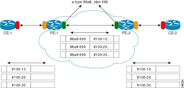
Layer 2 PDU Tunneling
S-Bridge Component
The S-bridge component is capable of inserting or removing a service provider VLAN (S-VLAN) for all traffic on a particular port. IEEE 802.1ad adds a new tag called a Service tag (S-tag) to all the ingress frames from a customer to the service provider.
The VLAN in the S-tag is used for forwarding the traffic in the service provider network. Different customers use different S-VLANs, which results in each customer's traffic being isolated. In the S-tag, provider bridges use an Ethertype value that is different from the standard 802.1Q Ethertype value, and do not understand the standard Ethertype. This difference makes customer traffic tagged with the standard Ethertype appear as untagged in the provider network so customer traffic is tunneled in the port VLAN of the provider port. The 802.1ad service provider user network interfaces (S-UNIs) and network to network interfaces (NNIs) implement the S-bridge component.
For example, a VLAN tag has a VLAN ID of 1, the C-tag Ethertype value is 8100 0001, the S-tag Ethertype value is 88A8 0001, and the class of service (CoS) is zero.
C-tag S-tag
-------------------------------------------------------
-----------------------------------------------
0x8100 | Priority bits | CFI | C-VLAN-ID 0x88A8 | Priority bits | 0 | S-VLAN-ID
-------------------------------------------------------
-----------------------------------------------
C-Bridge Component
All the C-VLANs entering on a UNI port in an S-bridge component are provided the same service (marked with the same S-VLAN). Although, C-VLAN components are not supported, a customer may want to tag a particular C-VLAN packet separately to differentiate between services. Provider bridges allow C-VLAN packet tagging with a provider edge bridge, called the C-bridge component of the provider bridge. C-bridge components are C-VLAN aware and can insert or remove a C-VLAN 802.1Q tag. The C-bridge UNI port is capable of identifying the customer 802.1Q tag and inserting or removing an S-tag on the packet on a per service instance or C-VLAN basis. A C-VLAN tagged service instance allows service instance selection and identification by C-VLAN. The 802.1ad customer user network interfaces (C-UNIs) implement the C-component.
MAC Addresses for Layer 2 Protocols
Customers' Layer 2 PDUs received by a provider bridge are not forwarded, so Layer 2 protocols running in customer sites do not know the complete network topology. By using a different set of addresses for the Layer 2 protocols running in provider bridges, IEEE 802.1ad causes customers' Layer 2 PDUs entering the provider bridge to appear as unknown multicast traffic and forwards it on customer ports (on the same S-VLAN). Customers' Layer 2 protocols can then run transparently.
Table 2-4 shows the Layer 2 MAC addresses reserved for the C-VLAN component.
Table 2-5 shows the Layer 2 MAC addresses reserved for an S-VLAN component. These addresses are a subset of the C-VLAN component addresses, and the C-bridge does not forward the provider's bridge protocol data units (BPDUs) to a customer network.
Guidelines for Handling BPDU
The general BPDU guidelines are listed here:
UNI-C Ports
The guidelines pertaining to UNI-C ports are:
•![]() VLAN-aware L2 protocols can be peered, tunneled, or dropped.
VLAN-aware L2 protocols can be peered, tunneled, or dropped.
•![]() Port L2 protocols can either be peered or dropped. They cannot be tunneled.
Port L2 protocols can either be peered or dropped. They cannot be tunneled.
Table 2-6 shows the Layer 2 PDU destination MAC addresses for customer-facing C-bridge UNI ports, and how frames are processed.
UNI-S Ports
The guidelines pertaining to UNI-S ports are:
•![]() Packets with C-Bridge addresses (00 - 0F) that are not part of S-Bridge addresses (01 - 0A) are treated as data packet (tunneled).
Packets with C-Bridge addresses (00 - 0F) that are not part of S-Bridge addresses (01 - 0A) are treated as data packet (tunneled).
•![]() VLAN-aware L2 protocols cannot be peered because the port is not C-VLAN aware. They can only be tunneled or dropped.
VLAN-aware L2 protocols cannot be peered because the port is not C-VLAN aware. They can only be tunneled or dropped.
•![]() Port L2 protocols can be peered, tunneled, or dropped.
Port L2 protocols can be peered, tunneled, or dropped.
Table 2-7 shows the Layer 2 PDU destination MAC addresses for customer-facing S-bridge UNI ports, and how frames are processed.
NNI Ports
The Dot1add NNI ports behave in the same way as the customer facing S-bridge ports, with the following exceptions:
•![]() On NNI ports, frames received with DA 01-80-C2-00-00-08 contain STP BPDU. The frames are received and transmitted. On S-UNI ports, any such frames that are received are dropped, and none are sent.
On NNI ports, frames received with DA 01-80-C2-00-00-08 contain STP BPDU. The frames are received and transmitted. On S-UNI ports, any such frames that are received are dropped, and none are sent.
•![]() On NNI ports, frames received with DA 01-80-C2-00-00-02 include CDP Pagp, VTP, DTP, and UDLD protocols.
On NNI ports, frames received with DA 01-80-C2-00-00-02 include CDP Pagp, VTP, DTP, and UDLD protocols.
7600 Action Table
Table 2-8 lists the actions performed on a packet when the packet is received with a specified destination MAC address.
Interoperability of QinQ and Dot1ad
The interoperability of QinQ and Dot1ad network enables the exchange of data frames between the networks. The 802.1Q network outer tag VLANs are mapped to the provider S-VLANs of the 802.1ad network.
Figure 2-2 illustrates the interoperability of a Dot1ad network and a QinQ network.
Figure 2-2
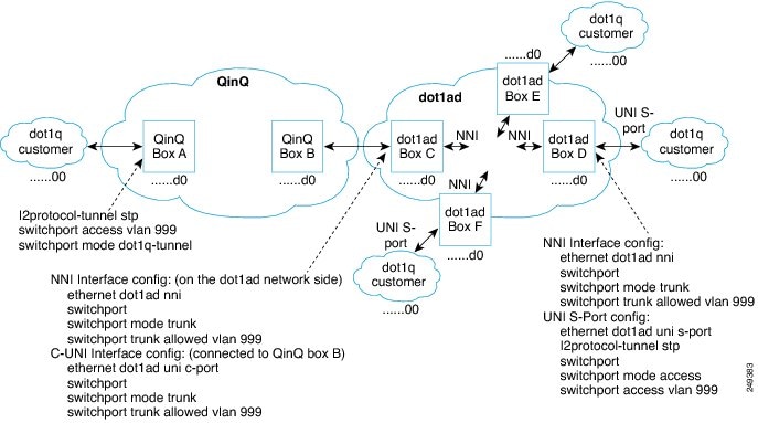
Interoperability of Dot1ad Network and a QinQ Network
How to Configure IEEE 802.1ad
This section contains the information about following procedures:
•![]() Configuring a Layer 2 Protocol Forward
Configuring a Layer 2 Protocol Forward
•![]() Configuring a Switchport for Translating QinQ to 802.1ad
Configuring a Switchport for Translating QinQ to 802.1ad
•![]() Configuring a Switchport (L2PT)
Configuring a Switchport (L2PT)
•![]() Configuring a Customer-Facing UNI-C Port with EVC
Configuring a Customer-Facing UNI-C Port with EVC
•![]() Configuring a Customer-Facing UNI-C Port and Switchport on NNI with EVC
Configuring a Customer-Facing UNI-C Port and Switchport on NNI with EVC
•![]() Configuring a Customer-Facing UNI-S Port with EVC
Configuring a Customer-Facing UNI-S Port with EVC
•![]() Configuring a Layer 3 Termination
Configuring a Layer 3 Termination
•![]() Displaying a Dot1ad Configuration
Displaying a Dot1ad Configuration
Configuring a Switchport
A switchport can be configured as a UNI-C port, UNI-S port, or NNI port.
UNI-C Port
A UNI-C port can be configured as either a trunk port or an access port. Perform the following tasks to configure a UNI-C port as an access port for 802.1ad.
SUMMARY STEPS
1. ![]() enable
enable
2. ![]() configure terminal
configure terminal
3. ![]() interface type number
interface type number
4. ![]() ethernet dot1ad {nni | uni {c-port | s-port}}
ethernet dot1ad {nni | uni {c-port | s-port}}
5. ![]() switchport
switchport
6. ![]() switchport mode {access | trunk}
switchport mode {access | trunk}
7. ![]() switchport access vlan vlan-id
switchport access vlan vlan-id
8. ![]() end
end
DETAILED STEPS
Perform the following tasks to configure a UNI-C port as a trunk port for 802.1ad.
SUMMARY STEPS
1. ![]() enable
enable
2. ![]() configure terminal
configure terminal
3. ![]() interface type number
interface type number
4. ![]() ethernet dot1ad {nni | uni {c-port | s-port}}
ethernet dot1ad {nni | uni {c-port | s-port}}
5. ![]() switchport
switchport
6. ![]() switchport mode {access | trunk}
switchport mode {access | trunk}
7. ![]() switchport trunk allowed vlan vlan-list
switchport trunk allowed vlan vlan-list
8. ![]() end
end
DETAILED STEPS
UNI-S Port
On a UNI-S port, all the customer VLANs that enter are provided with the same service. The port allows only access configuration. In this mode, the customer's port is configured as a trunk port. Therefore, the traffic entering the UNI-S port is tagged traffic.
Perform the following tasks to configure a UNI-S port as an access port for 802.1ad.
SUMMARY STEPS
1. ![]() enable
enable
2. ![]() configure terminal
configure terminal
3. ![]() interface type number
interface type number
4. ![]() switchport
switchport
5. ![]() switchport mode {access | trunk}
switchport mode {access | trunk}
6. ![]() ethernet dot1ad {nni | uni {c-port | s-port}}
ethernet dot1ad {nni | uni {c-port | s-port}}
7. ![]() switchport access vlan vlan-id
switchport access vlan vlan-id
8. ![]() end
end
DETAILED STEPS
NNI Port
NNI port allows only trunk configuration. On an NNI port, the frames received on all the allowed VLANs are bridged to the respective internal VLANs.
Perform the following tasks to configure an NNI port as a trunk port for 802.1ad.
SUMMARY STEPS
1. ![]() enable
enable
2. ![]() configure terminal
configure terminal
3. ![]() interface type number
interface type number
4. ![]() switchport
switchport
5. ![]() switchport mode {access | trunk}
switchport mode {access | trunk}
6. ![]() ethernet dot1ad {nni | uni {c-port | s-port}}
ethernet dot1ad {nni | uni {c-port | s-port}}
7. ![]() switchport trunk allowed vlan vlan-list
switchport trunk allowed vlan vlan-list
8. ![]() end
end
DETAILED STEPS
Examples
The following example shows how to configure a UNI-C port as an access port. In this example, all the frames that are received are bridged to one internal VLAN 1000. The transmitted frames do not have the access VLAN Dot1q tag.
router# configure terminal
router(config)#interface gig2/1
router(config-if)#ethernet dot1ad uni c-port
router(config-if)#switchport
router(config-if)#switchport mode access
router(config-if)#switchport access vlan 1000
The following example shows how to configure a UNI-C port as a trunk port. In this example, all the frames that are received on all allowed VLANs (1000 and 2000) are bridged to the respective internal VLANs. The transmitted frames have the respective internal VLAN Dot1q tag.
router# configure terminal
router(config)# interface gig2/1
router(config-if)# ethernet dot1ad uni c-port
router(config-if)# switchport
router(config-if)# switchport mode trunk
router(config-if)# switchport access vlan 1000, 2000
The following example shows how to configure a UNI-S port. In this example, all the frames that are received are bridged to one internal VLAN (999). The transmitted frames do not have the access VLAN Dot1q tag.
router# configure terminal
router(config)#interface gig2/1
router(config-if)#switchport
router(config-if)#switchport mode access
router(config-if)#ethernet dot1ad uni s-port
router(config-if)#switchport access vlan 999
The following example shows how to configure an NNI port. Only trunk configuration is allowed on an NNI port. In this example, all the frames that are received on all the allowed VLANs (999) are bridged to the respective internal VLANs. The transmitted frames have the respective internal VLAN Dot1q tag.
router# configure terminal
router(config)#interface gig2/1
router(config-if)#switchport
router(config-if)#switchport mode trunk
router(config-if)#ethernet dot1ad nni
router(config-if)#switchport trunk allowed vlan 999
The following example shows how to configure Dot1ad on an SVI:
router# configure terminal
router(config)#interface gig2/1
router(config-if)#ethernet dot1ad nni
router(config-if)#switchport
router(config-if)#switchport mode trunk
router(config-if)#switchport trunk allowed vlan 999
router(config)#interface vlan 999
router(config-if)#ip address 1.2.3.4 255.255.0.0
Configuring a Layer 2 Protocol Forward
Perform the following tasks to configure the Layer 2 protocol forward:
SUMMARY STEPS
1. ![]() enable
enable
2. ![]() configure terminal
configure terminal
3. ![]() interface type number
interface type number
4. ![]() switchport access valn vlan-id
switchport access valn vlan-id
5. ![]() ethernet dot1ad {nni | uni {c-port | s-port}}
ethernet dot1ad {nni | uni {c-port | s-port}}
6. ![]() l2protocol [ forward] [protocol]
l2protocol [ forward] [protocol]
7. ![]() end
end
DETAILED STEPS
Examples
The following example shows how to configure a Layer 2 protocol forward:
router# configure terminal
router(config)#interface gig3/0
router(config-if)#switchport access vlan 500
router(config-if)#ethernet dot1ad uni s-port
router(config-if)#l2protocol forward vtp
Configuring a Switchport for Translating QinQ to 802.1ad
Translating a QinQ port to 802.1ad involves configuring the port connecting to QinQ port and NNI port.
Perform the following tasks to configure a port connecting to the QinQ port.
SUMMARY STEPS
1. ![]() enable
enable
2. ![]() configure terminal
configure terminal
3. ![]() interface type number
interface type number
4. ![]() switchport mode {access | trunk}
switchport mode {access | trunk}
5. ![]() switchport trunk allowed vlan vlan-list
switchport trunk allowed vlan vlan-list
6. ![]() end
end
DETAILED STEPS
Perform the following tasks to configure an NNI port.
SUMMARY STEPS
1. ![]() enable
enable
2. ![]() configure terminal
configure terminal
3. ![]() interface type number
interface type number
4. ![]() ethernet dot1ad {nni | uni {c-port | s-port}}
ethernet dot1ad {nni | uni {c-port | s-port}}
5. ![]() switchport
switchport
6. ![]() switchport mode {access | trunk}
switchport mode {access | trunk}
7. ![]() switchport trunk allowed vlan vlan-list
switchport trunk allowed vlan vlan-list
8. ![]() end
end
DETAILED STEPS
Examples
The following example shows how to translate a QinQ port to 802.1ad. In this example, the peer router to gig1/1 multiplexes various customer VLANs into VLAN 1000.
router# configure terminal
router(config)#interface gig1/1
router(config-if)#switchport mode trunk
router(config-if)#switchport trunk allowed vlan 1000
router# configure terminal
router(config)#interface gig4/0
router(config-if)#ethernet dot1ad nni
router(config-if)#switchport
router(config-if)#switchport mode trunk
router(config-if)#switchport trunk allowed vlan 1000,1199
Configuring a Switchport (L2PT)
Configuring the switchport for L2PT is required to tunnel the STP packets from a customer on the dot1ad network to a customer on the QinQ network.
Perform the following tasks to configure the port connecting to the customer.
SUMMARY STEPS
1. ![]() enable
enable
2. ![]() configure terminal
configure terminal
3. ![]() interface type number
interface type number
4. ![]() switchport
switchport
5. ![]() ethernet dot1ad {nni | uni {c-port | s-port}}
ethernet dot1ad {nni | uni {c-port | s-port}}
6. ![]() no l2 protocol [peer | forward] [protocol]
no l2 protocol [peer | forward] [protocol]
7. ![]() l2protocol-tunnel [cdp | stp | vtp]
l2protocol-tunnel [cdp | stp | vtp]
8. ![]() switchport mode {access | trunk}
switchport mode {access | trunk}
9. ![]() end
end
DETAILED STEPS
Perform the following tasks to configure an NNI port.
SUMMARY STEPS
1. ![]() enable
enable
2. ![]() configure terminal
configure terminal
3. ![]() interface type number
interface type number
4. ![]() switchport
switchport
5. ![]() ethernet dot1ad {nni | uni {c-port | s-port}}
ethernet dot1ad {nni | uni {c-port | s-port}}
6. ![]() switchport mode {access | trunk}
switchport mode {access | trunk}
7. ![]() end
end
DETAILED STEPS
Examples
The following example shows how to tunnel the STP packets from a customer on the Dot1ad network to a customer on a QinQ network:
router# configure terminal
router(config)#interface gig1/0
router(config-if)#switchport
router(config-if)#ethernet dot1ad uni s-port
router(config-if)#no l2protocol forward
router(config-if)#l2protocol-tunnel stp
router(config-if)#switchport mode access
router# configure terminal
router(config)#interface gig4/0
router(config-if)#switchport
router(config-if)#ethernet dot1ad nni
router(config-if)#switchport mode trunk
Configuring a Customer-Facing UNI-C Port with EVC
Perform the following tasks to configure a UNI-C port.
SUMMARY STEPS
1. ![]() enable
enable
2. ![]() configure terminal
configure terminal
3. ![]() interface type number
interface type number
4. ![]() ethernet dot1ad {nni | uni {c-port | s-port}}
ethernet dot1ad {nni | uni {c-port | s-port}}
5. ![]() service instance id service-type
service instance id service-type
6. ![]() encapsulation dot1q vlan-id second-dot1q {any | vlan-id} [native]
encapsulation dot1q vlan-id second-dot1q {any | vlan-id} [native]
7. ![]() bridge-domain vlan-id
bridge-domain vlan-id
8. ![]() service instance id service-type
service instance id service-type
9. ![]() encapsulation dot1q vlan-id second-dot1q {any | vlan-id} [native]
encapsulation dot1q vlan-id second-dot1q {any | vlan-id} [native]
10. ![]() bridge-domain vlan-id
bridge-domain vlan-id
11. ![]() end
end
DETAILED STEPS
Perform the following tasks to configure an NNI port.
SUMMARY STEPS
1. ![]() enable
enable
2. ![]() configure terminal
configure terminal
3. ![]() interface type number
interface type number
4. ![]() ethernet dot1ad {nni | uni {c-port | s-port}}
ethernet dot1ad {nni | uni {c-port | s-port}}
5. ![]() service instance id service-type
service instance id service-type
6. ![]() encapsulation dot1q vlan-id second-dot1q {any | vlan-id} [native]
encapsulation dot1q vlan-id second-dot1q {any | vlan-id} [native]
7. ![]() rewrite ingress tag pop 1 symmetric
rewrite ingress tag pop 1 symmetric
8. ![]() bridge-domain vlan-id
bridge-domain vlan-id
9. ![]() service instance id service-type
service instance id service-type
10. ![]() encapsulation dot1q vlan-id second-dot1q {any | vlan-id} [native]
encapsulation dot1q vlan-id second-dot1q {any | vlan-id} [native]
11. ![]() rewrite ingress tag pop 1 symmetric
rewrite ingress tag pop 1 symmetric
12. ![]() bridge-domain vlan-id
bridge-domain vlan-id
13. ![]() end
end
DETAILED STEPS
Examples
The following example shows how to configure a customer-facing UNI port. In this example, a dot1q frame coming on VLAN 50 matches service instance 1, and on the ingress port, the rewrite command pushes the 1000 outer-vlan.
router# configure terminal
router(config)#interface gig1/1
router(config-if)#ethernet dot1ad uni c-port
router(config-if)#service instance 1 ethernet
router(config-if)#encapsulation dot1q 1-100
router(config-if)#bridge-domain 1000
router(config-if)#service instance 2 ethernet
router(config-if)#encapsulation dot1q 102-4904
router(config-if)#bridge-domain 500
router# configure terminal
router(config)#interface gig4/1
router(config-if)#ethernet dot1ad nni
router(config-if)#service instance 1 ethernet
router(config-if)#encapsulation dot1q 1000 second dot1q 1-100
router(config-if)#rewrite ingress tag pop 1 symmetric
router(config-if)#bridge-domain 1000
router(config-if)#service instance 2ethernet
router(config-if)#encapsulation dot1q 500 second dot1q 102-4904
router(config-if)#rewrite ingress tag pop 1 symmetric
router(config-if)#bridge-domain 500
Configuring a Customer-Facing UNI-C Port and Switchport on NNI with EVC
Perform the following tasks to configure a UNI-C port.
SUMMARY STEPS
1. ![]() enable
enable
2. ![]() configure terminal
configure terminal
3. ![]() interface type number
interface type number
4. ![]() ethernet dot1ad {nni | uni {c-port | s-port}}
ethernet dot1ad {nni | uni {c-port | s-port}}
5. ![]() service instance id service-type
service instance id service-type
6. ![]() encapsulation dot1q vlan-id second-dot1q {any | vlan-id} [native]
encapsulation dot1q vlan-id second-dot1q {any | vlan-id} [native]
7. ![]() bridge-domain vlan-id
bridge-domain vlan-id
8. ![]() service instance id service-type
service instance id service-type
9. ![]() encapsulation dot1q vlan-id second-dot1q {any | vlan-id} [native]
encapsulation dot1q vlan-id second-dot1q {any | vlan-id} [native]
10. ![]() bridge-domain vlan-id
bridge-domain vlan-id
11. ![]() end
end
DETAILED STEPS
Perform the following tasks to configure an NNI port.
SUMMARY STEPS
1. ![]() enable
enable
2. ![]() configure terminal
configure terminal
3. ![]() interface type number
interface type number
4. ![]() ethernet dot1ad {nni | uni {c-port | s-port}}
ethernet dot1ad {nni | uni {c-port | s-port}}
5. ![]() switchport
switchport
6. ![]() switchport mode {access | trunk}
switchport mode {access | trunk}
7. ![]() switchport trunk allowed vlan vlan-list
switchport trunk allowed vlan vlan-list
8. ![]() end
end
DETAILED STEPS
Examples
The following example shows how to configure a customer-facing UNI-C port and switchport on NNI with EVC:
router# configure terminal
router(config)#interface gig1/1
router(config-if)#ethernet dot1ad uni c-port
router(config-if)#service instance 1 ethernet
router(config-if)#encapsulation dot1q 1-100
router(config-if)#bridge-domain 1000
router(config-if)#service instance 2 ethernet
router(config-if)#encapsulation dot1q 102-4904
router(config-if)#bridge-domain 500
router# configure terminal
router(config)#interface gig4/0
router(config-if)#switchport
router(config-if)#ethernet dot1ad uni
router(config-if)#switchport mode trunk
router(config-if)#switchport allowed vlan 1000,500
Configuring a Customer-Facing UNI-S Port with EVC
Perform the following tasks to configure a UNI-S port.
SUMMARY STEPS
1. ![]() enable
enable
2. ![]() configure terminal
configure terminal
3. ![]() interface type number
interface type number
4. ![]() service instance id service-type
service instance id service-type
5. ![]() ethernet dot1ad {nni | uni {c-port | s-port}}
ethernet dot1ad {nni | uni {c-port | s-port}}
6. ![]() encapsulation default
encapsulation default
7. ![]() bridge-domain vlan-id
bridge-domain vlan-id
8. ![]() end
end
DETAILED STEPS
Perform the following tasks to configure an NNI port.
SUMMARY STEPS
1. ![]() enable
enable
2. ![]() configure terminal
configure terminal
3. ![]() interface type number
interface type number
4. ![]() service instance id service-type
service instance id service-type
5. ![]() ethernet dot1ad {nni | uni {c-port | s-port}}
ethernet dot1ad {nni | uni {c-port | s-port}}
6. ![]() encapsulation dot1q vlan-id second-dot1q {any | vlan-id} [native]
encapsulation dot1q vlan-id second-dot1q {any | vlan-id} [native]
7. ![]() rewrite ingress tag pop 1 symmetric
rewrite ingress tag pop 1 symmetric
8. ![]() bridge-domain vlan-id
bridge-domain vlan-id
9. ![]() end
end
DETAILED STEPS
Examples
The following example shows how to configure an NNI port:
router# configure terminal
router(config)#interface gig1/1
router(config-if)#service instance 1 ethernet
router(config-if)#ethernet dot1ad nni
router(config-if)#encapsulation dot1q 1000
router(config-if)#rewrite ingress tag pop 1 symmetric
router(config-if)#bridge-domain 1000
Configuring a Layer 3 Termination
Perform the following tasks to configure a Layer 3 termination.
SUMMARY STEPS
1. ![]() enable
enable
2. ![]() configure terminal
configure terminal
3. ![]() interface type number
interface type number
4. ![]() ethernet dot1ad {nni | uni {c-port | s-port}}
ethernet dot1ad {nni | uni {c-port | s-port}}
5. ![]() interface type number
interface type number
6. ![]() encapsulation dot1q vlan-id second-dot1q {any | vlan-id} [native]
encapsulation dot1q vlan-id second-dot1q {any | vlan-id} [native]
7. ![]() ip address ip-address mask
ip address ip-address mask
8. ![]() end
end
DETAILED STEPS
Examples
The following example shows how to configure a Layer 3 termination. Note that Layer 3 is supported only on trunk interfaces.
router# configure terminal
router(config)#interface gig3/0
router(config-if)#ethernet dot1ad nni
router(config)#interface gig3/0/0.1
router(config-if)#encapsulation dot1q 10 second dot1q 10
router(config-if)#ip address 1.2.3.4 255.255.0.0
The following example shows how to configure a Layer 3 termination on an SVI:
router# configure terminal
router(config)#interface gig4/1
router(config-if)#ethernet dot1ad nni
router(config-if)#service instance 1 ethernet
router(config-if)#encapsulation dot1q 200 second dot1q 300
router(config-if)#rewrite ingress tag pop 2 symmetric
router(config-if)#bridge-domain 50
router(config-if)#service instance 2 ethernet
router(config-if)#encapsulation dot1q 300
router(config-if)#rewrite ingress tag pop 1 symmetric
router(config-if)#bridge-domain 60
router(config)#interface vlan 50
router(config-if)#ip address 2.3.4.5 255.255.0.0
router(config)#interface vlan 60
router(config-if)#ip address 3.4.5.6 255.255.0.0
Displaying a Dot1ad Configuration
You can display a Dot1ad configuration using the show ethernet dot1ad command. This command displays the Dot1ad configuration for all interfaces. To display the configuration on a particular interface, use the show ethernet dot1ad interface command.
The following example shows how to display a Dot1ad configuration on all interfaces:
router# show ethernet dot1ad
Interface: GigabitEthernet4/0/1
DOT1AD C-Bridge Port
L2protocol pass cdp stp vtp dtp pagp dot1x lacp
Interface: GigabitEthernet4/0/2
DOT1AD C-Bridge Port
L2protocol pass cdp stp vtp dtp pagp dot1x lacp
Troubleshooting Dot1ad
The following section describes how to troubleshoot Dot1ad.
Note ![]() The show commands in these examples should be run from a line card console.
The show commands in these examples should be run from a line card console.
•![]() How do I verify the Dot1ad configuration on a switchport on an X40G card?
How do I verify the Dot1ad configuration on a switchport on an X40G card?
Run the following command to verify the Dot1ad configuration:
XYZ-PE1-dfc1#show platform npc switchport interface gi 1/2
[GigabitEthernet1/2]
status [valid, -, applied, enabled]
src_index [0x1]
rpcb [0x178BB9C4]
xlif_id [4097]
xlif_handle [type:[3] hwidb:[0x20E97F08] if_number:[1121]]
ft_bits [0x2]
ing_ctrl_ft_bits [0x2]
egr_ctrl_ft_bits [0x2]
port vlan [1]
mode ingress [NORMAL] egress [NORMAL]
dot1q_tunnel [No]
native tagging [No]
PVLAN isolated or community [No] promiscuous [No]
ingress vlan-translation [No] BPDU [No]
egress vlan-translation [No] BPDU [No]
dot1ad [Yes] <<<<<<<<<<<<
ethertype [0x88A8] <<<<<<<<<<<
Ingress Stat ID: 778698
Egress Stat ID: 778700
VLAN List:
1
num of vlans [1]
XYZ-PE1-dfc1#
•![]() How do I verify the Dot1ad configuration on the ports with EVCs on an X40G card?
How do I verify the Dot1ad configuration on the ports with EVCs on an X40G card?
Run the following command to verify the Dot1ad configuration:
XYZ-PE1-dfc1#show platform npc xlif interface gi 1/2 efp 1
EFP XLIF(GigabitEthernet1/2, efp1)[np0] = 4136
Ingress XLIF table fields
Feature common enable: 0x1
Feature enable: 0x1
Feature bits: 0x1
Control common bits: 0x0
Control feature bits: 0x0
Control rewrite opcode: 0x0
Reserved 1: 0x0
Match cond 0x1
Entry valid: 0x1
Dbus VLAN: 30
QoS policy ID: 0
ACL ID: 0
Statistics ID: 450976
Inner rewrite VLAN: 0
Outer rewrite VLAN: 0
QoS flow ID: 0
Feature data: 00000000 40000000 AAA80000 E0000829
EFP admin down state 0x0
----- Bridge data ------
layer2_acl_index: 0x00000000
evc_feat_data.ip_src_guard : 0x0
evc_feat_data.mst_evc : 0x1
evc_feat_data.layer2_acl : 0x0
EVC - Mac Security: 0x0
evc_feat_data.sacl : 0x0
evc_feat_data.layer2_acl_statid: 0
PDT: 0xAAA8
ipsg_label: 0
block_data: 0x0
block_l2bpdu: 0x0
split_h: 0x0
imp_ltl: 0x0829
EFP dot1ad port type 0x3 <<<<<<<<
EFP CDP forward 0x1 <<<<<<<<
EFP DTP forward 0x0
EFP VTP forward 0x0
EFP STP forward 0x0
EFP DOT1X forward 0x0
Egress XLIF table fields
Feature common enable: 0x1
Feature enable: 0x1
Feature bits: 0x01
Control common bits: 0x00
Control feature bits: 0x00
Control rewrite opcode: 0x00
Port: 0x1
Match cond 0x1
Entry valid: 0x1
Dbus VLAN: 30
QoS policy ID: 0
ACL ID: 0
Statistics ID: 450980
Inner rewrite VLAN: 0
Outer rewrite VLAN: 0
QoS flow ID: 0
IP Session en : 0
Multicast en : 0
Feature data 0 0x00000000
Intf etype: 0x00008064
Post Filter Opcode 0x00000008
Pre Filter Opcode 0x00000000
Pre Tag Outer 0x00000000
Pre Tag Inner 0x00000000
Post Filter Vlan high 0x00000064
Post Filter Vlan low 0x00000064
Post Filter Vlan outer 0x00000000
EVC - MST: 0x1
EVC etype 0x8100
CFM MEP Level 0x00000008
CFM MIP Level 0x00000008
CFM disable 0x0
MIP filtering 0x0
block_data: 0x0
block_l2bpdu: 0x0
sacl: 0x0
sacl index: 0x0000
sacl statid: 0x00000
XYZ-PE1-dfc1#
XYZ-PE1-dfc1#
•![]() How do I verify the L2protocol forwarding on a regular L3 switchports?
How do I verify the L2protocol forwarding on a regular L3 switchports?
Run the following command to verify the L2protocol forwarding:
XYZ-PE1-dfc1# show platform npc xlif 0 port_sram 1
........................
dot1ad port type: 0x0002 <<<<<<<<<
l2proto cdp fwd: 0x0001 <<<<<<<<<
l2proto dtp fwd: 0x0000
l2proto vtp fwd: 0x0000
l2proto stp fwd: 0x0000
l2proto dot1x fwd: 0x0000
..............................................
•![]() How do I verify the Dot1ad configuration on ES20 cards?
How do I verify the Dot1ad configuration on ES20 cards?
–![]() For switchports, run the following command:
For switchports, run the following command:
XYZ-PE1-dfc1#show platform hardware dot1ad l2protocfg port <port-num>
–![]() For EVCs, run the following command:
For EVCs, run the following command:
XYZ-PE1-dfc1# show platform soft efp-client interface gi x/0/y efp-id l2protocfg
–![]() To display the default values, run the following commands:
To display the default values, run the following commands:
XYZ-PE1-dfc1#show platform hardware dot1ad l2protocfg defaults ?
<0-2> 0=c-uni, 1=s-uni, 2=nni
XYZ-PE1-dfc1#show platform hardware dot1ad l2protocfg defaults 0 ?
<0-2> 0=L3, 1=BD, 2=XCON
XYZ-PE1-dfc1#show platform hardware dot1ad l2protocfg defaults 0 2
Raw Data :000FFF77 FFFCFF51
L2 Proto Configs :
Protocol IEEE CISCO
------------------------------------
CDP : FRWD FRWD
VTP : FRWD FRWD
DTP : FRWD FRWD
Others : PEER PEER
802.1d protocols : 01:80:C2:00:00:XX
XX | Config XX | Config XX | Config XX | Config
----------- ----------- ----------- -----------
00 : PEER 01 : DROP 02 : PEER 03 : PEER
04 : FRWD 05 : FRWD 06 : FRWD 07 : FRWD
08 : DROP 09 : FRWD 0A : FRWD 0B : FRWD
0C : FRWD 0D : FRWD 0E : FRWD 0F : FRWD
All Bridge (0180C2000010)= FRWD
Group = PEER
PVST = FRWD
Configuring Layer 2 Features
This section provides ES20 line card-specific information about configuring the Layer 2 interworking features on the Cisco 7600 series router. It includes the following topics:
•![]() Configuring Flexible QinQ Mapping and Service Awareness on 7600-ESM-2X10GE and 7600-ESM-20X1GE
Configuring Flexible QinQ Mapping and Service Awareness on 7600-ESM-2X10GE and 7600-ESM-20X1GE
•![]() Configuring Flexible Service Mapping Based on CoS and Ethertype
Configuring Flexible Service Mapping Based on CoS and Ethertype
•![]() Configuring the Backup Interface for Flexible UNICross-Bundling
Configuring the Backup Interface for Flexible UNICross-Bundling
•![]() Multichassis Support for Link Aggregation Control Protocol
Multichassis Support for Link Aggregation Control Protocol
•![]() Configuring the Backup Interface for Flexible UNI
Configuring the Backup Interface for Flexible UNI
•![]() Configuring Broadcast Storm Control on Switchports and Ports with Ethernet Virtual Connections
Configuring Broadcast Storm Control on Switchports and Ports with Ethernet Virtual Connections
•![]() Configuring Asymmetric Carrier-Delay
Configuring Asymmetric Carrier-Delay
•![]() Configuring MST on EVC Bridge Domain
Configuring MST on EVC Bridge Domain
Cross-Bundling
Follow these restrictions and guidelines during cross-bundling various linecards:
•![]() ES20 and ES+ cross-bundling is not supported.
ES20 and ES+ cross-bundling is not supported.
•![]() Any LAN card, and ES20/ES+ cross-bundling is not supported.
Any LAN card, and ES20/ES+ cross-bundling is not supported.
Configuring EVC EtherChannel and LACP over EVC Port Channel
An Ethernet link bundle or port channel is an aggregation of up to eight physical Ethernet links to form a single logical link for L2/L3 forwarding. Bundled Ethernet ports are used to increase the capacity of the logical link and provide high availability and redundancy. The EVC EtherChannel feature provides support for EtherChannels on Ethernet Virtual Connection Services (EVCS) service instances.
For more information on EtherChannels, and how to configure EtherChannels on Layer 2 or Layer 3 LAN ports, refer: http://www.cisco.com/en/US/docs/routers/7600/ios/12.2SXF/configuration/guide/channel.html
The EVC EtherChannel feature supports MPBE, local connect, and cross connect service types. IEEE 802.3ad/Link Aggregation Control Protocol (LACP) provides an association of port channels. This feature supports service instances over bundled Ethernet links.
Ethernet flow points (EFPs) are configured on a port channel. The traffic, carried by the EFPs, is load balanced across member links. EFPs on a port channel are grouped and each group is associated with one member link. Ingress traffic for a single EVC can arrive on any member of the bundle. All egress traffic for an EFP uses only one of the member links. Load balancing is achieved by grouping EFPs and assigning them to a member link. In default load balancing, the user has no control over how the EFPs are grouped together, and sometimes the EFP grouping is not ideal. As a workaround, use manual load balancing to control the EFP grouping.
The scalability for a link-bundling EVC is 16k per chassis. Port Channel EVC scalability for ES20 cards is dependent on the same factors as EVCs configured on physical interfaces, with the number of member links and their distribution across PXFs as an additional parameter. EVC port channel QoS leverages EVC QoS infrastructure
Restrictions and Usage Guidelines
When configuring EVC EtherChannel, follow these restrictions and usage guidelines:
•![]() All member links of the port channel are on Cisco 7600-ES20-GE line cards.
All member links of the port channel are on Cisco 7600-ES20-GE line cards.
•![]() Bridge-domain, cross connect, connect EVCs, switchports, and IP subinterfaces are allowed over the port-channel interface and the main interface.
Bridge-domain, cross connect, connect EVCs, switchports, and IP subinterfaces are allowed over the port-channel interface and the main interface.
Note ![]() For a port with a switchport, you can use the service instance ethernet command to create a service instance to support OAM requirements and not data traffic.
For a port with a switchport, you can use the service instance ethernet command to create a service instance to support OAM requirements and not data traffic.
•![]() The EFP limit decreases by the number of member links on the NP. Egs: If there are 4 members within the same NP, the EVC limit on the NP decreases to 2000 that ie (8000/4).
The EFP limit decreases by the number of member links on the NP. Egs: If there are 4 members within the same NP, the EVC limit on the NP decreases to 2000 that ie (8000/4).
•![]() If you configure a physical port as part of a channel group, you cannot configure EVCs on that physical port.
If you configure a physical port as part of a channel group, you cannot configure EVCs on that physical port.
•![]() SPAN is not supported on an EVC source and destination.
SPAN is not supported on an EVC source and destination.
•![]() You cannot configure switchport on a physical port that is part of an EVC port channel.
You cannot configure switchport on a physical port that is part of an EVC port channel.
•![]() You can apply QoS policies on EVCs on a port channel, except that ingress microflow policing is not supported. For more information on configuring QoS with EVCs, see "Configuring QoS on the Cisco 7600 Series Ethernet Services 20G Line Card".
You can apply QoS policies on EVCs on a port channel, except that ingress microflow policing is not supported. For more information on configuring QoS with EVCs, see "Configuring QoS on the Cisco 7600 Series Ethernet Services 20G Line Card".
•![]() For HQoS and flat policies applied on an EVCS at the egress, the total guaranteed bandwidth of all policies on the EVCS belonging to the port channel cannot exceed the link rate (1 Gbps for 7600-ESM-20X1GE and 10 Gbps for 7600-ESM-2X10GE).
For HQoS and flat policies applied on an EVCS at the egress, the total guaranteed bandwidth of all policies on the EVCS belonging to the port channel cannot exceed the link rate (1 Gbps for 7600-ESM-20X1GE and 10 Gbps for 7600-ESM-2X10GE).
•![]() You cannot use the bandwidth percent command on EVC port channels with Cisco 7600-ES20-GE line cards.
You cannot use the bandwidth percent command on EVC port channels with Cisco 7600-ES20-GE line cards.
SUMMARY STEPS
1. ![]() enable
enable
2. ![]() configure terminal
configure terminal
3. ![]() interface port channel
interface port channel
4. ![]() [no] ip address
[no] ip address
5. ![]() [no] service instance id {Ethernet service-name}
[no] service instance id {Ethernet service-name}
6. ![]() encapsulation dot1q vlan-id
encapsulation dot1q vlan-id
7. ![]() rewrite ingress tag {push {dot1q vlan-id | dot1q vlan-id second-dot1q vlan-id | dot1ad vlan-id dot1q vlan-id} | pop {1 | 2} | translate {1-to-1 {dot1q vlan-id | dot1ad vlan-id}| 2-to-1 dot1q vlan-id | dot1ad vlan-id}| 1-to-2 {dot1q vlan-id second-dot1q vlan-id | dot1ad vlan-id dot1q vlan-id} | 2-to-2 {dot1q vlan-id second-dot1q vlan-id | dot1ad vlan-id dot1q vlan-id}} [symmetric]
rewrite ingress tag {push {dot1q vlan-id | dot1q vlan-id second-dot1q vlan-id | dot1ad vlan-id dot1q vlan-id} | pop {1 | 2} | translate {1-to-1 {dot1q vlan-id | dot1ad vlan-id}| 2-to-1 dot1q vlan-id | dot1ad vlan-id}| 1-to-2 {dot1q vlan-id second-dot1q vlan-id | dot1ad vlan-id dot1q vlan-id} | 2-to-2 {dot1q vlan-id second-dot1q vlan-id | dot1ad vlan-id dot1q vlan-id}} [symmetric]
8. ![]() [no] bridge-domain bridge-id
[no] bridge-domain bridge-id
9. ![]() channel-group 5 mode on | off
channel-group 5 mode on | off
or
channel-group 5 mode active | passive
Note ![]() The channel-group command options on/off are applicable when configuring port channel over EVC and the options active/passive are applicable when configuring port channel over EVC with LACP.
The channel-group command options on/off are applicable when configuring port channel over EVC and the options active/passive are applicable when configuring port channel over EVC with LACP.
DETAILED STEPS
Examples
In this example, a single port channel interface is created with three possible member links from slots 1 and 2.
Router(config)# interface port channel5
Router(config-if)# no ip address
Router(config-if)# service instance 1 ethernet
Router(config-if-srv)# encapsulation dot1q 350
Router(config-if-srv)# rewrite ingress tag pop 1 symmetric
Router(config-subif)# bridge-domain 350
!
Router(config-if)# service instance 2 ethernet
Router(config-if-srv)# encapsulation dot1q 400
Router(config-if-srv)# rewrite ingress tag pop 1 symmetric
Router(config-subif)# bridge-domain 350
Router(config-if)# service instance 3 ethernet
Router(config-if-srv)# encapsulation dot1q 500
Router(config-if-srv)# rewrite ingress tag pop 1 symmetric
Router(config-subif)# bridge-domain 370
!
Router(config)# interface port channel5.1
Router(config-if-srv)# encapsulation dot1Q 500 second-dot1q 300
Router(config-if)# ip address 60.0.0.1 255.0.0.0
!
Router(config)# interface GigabitEthernet1/0/0
Router(config-if)# channel-group 5 mode on
Router(config)# interface GigabitEthernet1/0/1
Router(config-if)# channel-group 5 mode on
Router(config)# interface GigabitEthernet2/0/1
Router(config-if)# channel-group 5 mode on
The next example shows scalable Eompls and EVC connect sample configuration.
Router#enable
Router#configure terminal
Router(config)#interface GigabitEthernet 3/0/0
Router(config-if)#service instance 10 ethernet
Router(config-srv)#encapsulation dot1q 20
Router(config-if-srv)#rewrite ingress tag pop 1 sym
Router(config-if-srv)#exit
Router(config-if)#exit
Router(config)#interface GigabitEthernet 3/0/1
Router(config-if)#service instance 12 ethernet
Router(config-srv)#encapsulation dot1q 30
Router(config-if-srv)#rewrite ingress tag pop 1 sym
Router(config-if-srv)#exit
Router(config-if)#exit
Router(config)#connect TEST GigabitEthernet 3/0/0 10 GigabitEthernet 3/0/1 12
Router#sh connection all
ID Name Segment 1 Segment 2 State
================================================================================
57 TEST Gi3/0/0:10 Gi3/0/1:12 UP
Here is a typical QoS configuration.
Router(config)# interface port channel10
Router(config-if)# no ip address
Router(config-if)# mls qos trust cos
Router(config-if)# service instance 1 ethernet
Router(config-if-srv)# encapsulation dot1q 11
Router(config-if-srv)# rewrite ingress tag pop 1 symmetric
Router(config-if)# service-policy input x
Router(config-if)# service-policy output y
Router(config-subif)# bridge-domain 1500
Here is the configuration for LACP over a configured EVC port channel, on an interface:
Router(config-if)# channel-group 5 mode ?
active Enable LACP unconditionally
auto Enable PAgP only if a PAgP device is detected
desirable Enable PAgP unconditionally
on Enable EtherChannel only
passive Enable LACP only if a LACP device is detected
Router(config-if)#channel-group 5 mode active
Router(config-if)#channel-group 5 mode passive
Here are LACP EVC Port channel for Fast Switchover (1:1 redundancy) sample configuration outputs.
Port channel Configuration
Router(config-if)#interface port channel102
Router(config-if)#mtu 9216
Router(config-if)#no ip address
Router(config-if)#lacp fast-switchover
Router(config-if)#lacp max-bundle 1
Router(config-if)#service instance 50 ethernet
Router(config-if)# encapsulation dot1q 50
Router(config-if)# rewrite ingress tag pop 1 symmetric
Router(config-if)# service-policy output lacp-parent
Router(config-if)# bridge-domain 50
Member links configuration
Router(config-if)#interface GigabitEthernet3/0/12
Router(config-if)#mtu 9216
Router(config-if)#no ip address
Router(config-if)#no mls qos trust
Router(config-if)#lacp rate fast
Router(config-if)#channel-protocol lacp
Router(config-if)#channel-group 102 mode active
Verification
Use the following commands to verify operation.
Multichassis Support for Link Aggregation Control Protocol
Configured at the edge of a provider's network, Multichassis Link Aggregation Control Protocol (MLACP) features performs the following actions:
•![]() Uses dual-homed devices (DHD) to provide network redundancy between two or more service provider networks.
Uses dual-homed devices (DHD) to provide network redundancy between two or more service provider networks.
•![]() Allows the LACP state machine and protocol to operate in a dual- homed mode.
Allows the LACP state machine and protocol to operate in a dual- homed mode.
Each switch is a point of attachments (PoA), where one PoA is active, and the other is a standby, and the active PoA executes the multichassis link aggregation group with a DHD. A virtual LACP peer on the PoA is created giving the impression that a DHD is connected to one node.
Figure 2-3 shows the placement of PoAs and DHDs in an MLACP configuration.Figure 2-2
Figure 2-3 Placement of PoAs and DHDs in an MLACP Implementation
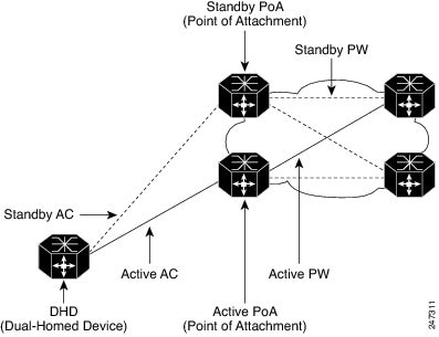
The status of the PoAs during traffic relay are:
•![]() The two PoAs form a redundancy group, and only one of the PoAs is active at any given time.
The two PoAs form a redundancy group, and only one of the PoAs is active at any given time.
•![]() Only two PoAs form a redundancy group; however, you can configure a maximum of 50 redundancy groups connecting to other DHDs.
Only two PoAs form a redundancy group; however, you can configure a maximum of 50 redundancy groups connecting to other DHDs.
•![]() Active links exist only between a DHD and active PoAs. None of the links between the DHD and the standby PoA relay traffic other than Bridge Protocol Data Unit (BPDU)s.
Active links exist only between a DHD and active PoAs. None of the links between the DHD and the standby PoA relay traffic other than Bridge Protocol Data Unit (BPDU)s.
•![]() The state of the etherchannel interface on a standby PoA is UP.
The state of the etherchannel interface on a standby PoA is UP.
A switchover from an active PoA to a standby PoA occurs when there is a failure on the:
•![]() Uplink port on the DHD
Uplink port on the DHD
•![]() DHD's uplink
DHD's uplink
•![]() Downlink port on an active PoA
Downlink port on an active PoA
•![]() Active PoA node
Active PoA node
•![]() Active PoA uplinks
Active PoA uplinks
•![]() Cable failure
Cable failure
The default switchover mechanism uses dynamic port priority changes on the port channel and member link(s) to provide revertive mode and nonrevertive mode options. The default operation in a multi- chassis LACP is revertive.
Bruteforce is a switchover mechanism where the member link is in a err-disable state after a switchover. To recover the port channel and enable the member link on a new standby PoA, use the err disable recovery cause mlacp-minlink command in the global configuration mode.
Use the lacp max-bundle command in the following modes:
•![]() PoA based: Command is executed on the PoA.
PoA based: Command is executed on the PoA.
•![]() Shared based: Command is executed on the PoA and DHD.
Shared based: Command is executed on the PoA and DHD.
•![]() DHD based: Command is executed on the DHD.
DHD based: Command is executed on the DHD.
Use the lacp max-bundle command on all the PoAs to operate in the PoA control and shared control modes. The max-bundle value argument should not be less than the total number of links in the Link Aggregation Group (LAG) that are connected to the PoA. Each PoA may be connected to the DHD with a different number of links for the LAG and, therefore, configured with a different value for the max-bundle value argument.
Note ![]() The lacp failover brute-force command cannot be used with a nonrevertive configuration.
The lacp failover brute-force command cannot be used with a nonrevertive configuration.
Requirements and Restrictions
Follow these requirements and restrictions when configuring the MLACP feature in a ES20 line card:
•![]() Supported only on ES20 and ES40 line cards, all member links on a port-channel should be on same type of line card.
Supported only on ES20 and ES40 line cards, all member links on a port-channel should be on same type of line card.
•![]() Cisco IOS Release 12.2(33)SRE supports service instances only on an MLACP port-channel.
Cisco IOS Release 12.2(33)SRE supports service instances only on an MLACP port-channel.
•![]() A PoA may be active for one port-channel, and standby for a different port-channel.
A PoA may be active for one port-channel, and standby for a different port-channel.
•![]() The maximum number of port-channels supported on a PoA is 256.
The maximum number of port-channels supported on a PoA is 256.
•![]() In any LACP configuration, ensure that the numerical value of the system-priority of the virtual LACP instance on the PoAs is lower (higher priority) than that on the DHD for all control variants.
In any LACP configuration, ensure that the numerical value of the system-priority of the virtual LACP instance on the PoAs is lower (higher priority) than that on the DHD for all control variants.
•![]() It is not recommended to configure different max bundle configurations on a PoA. For example, if DHD 1 to PoA has 4 links, PoA2 should also have 4 links.
It is not recommended to configure different max bundle configurations on a PoA. For example, if DHD 1 to PoA has 4 links, PoA2 should also have 4 links.
•![]() Links can be successfully aggregated based on the following constraints:
Links can be successfully aggregated based on the following constraints:
–![]() Links should be from the same line card type.
Links should be from the same line card type.
–![]() QoS should be validated.
QoS should be validated.
–![]() Port-channel hashing should be identical for two links.
Port-channel hashing should be identical for two links.
–![]() Flowcontrol should match.
Flowcontrol should match.
•![]() When Cisco 7600 routers are used to form a redundancy group within a PoA, the member links should adhere to the constraints listed in the previous paragraph. These constraints are not validated across PoAs and you should ensure that configuration between the two PoAs are identical.
When Cisco 7600 routers are used to form a redundancy group within a PoA, the member links should adhere to the constraints listed in the previous paragraph. These constraints are not validated across PoAs and you should ensure that configuration between the two PoAs are identical.
•![]() Ensure that the etherchannel usage configuration is identical on the two PoAs.
Ensure that the etherchannel usage configuration is identical on the two PoAs.
•![]() The maximum bundle value on a PoA is 8.
The maximum bundle value on a PoA is 8.
•![]() A maximum of two PoAs in a redundancy group and 50 redundancy groups per node are supported.
A maximum of two PoAs in a redundancy group and 50 redundancy groups per node are supported.
•![]() Multiple Spanning Tree (MST) on an EVC is not supported on MLACP etherchannel ports.
Multiple Spanning Tree (MST) on an EVC is not supported on MLACP etherchannel ports.
•![]() Reverse Layer 2 Gateway Protocol (RL2GP) with MLACP is not supported.
Reverse Layer 2 Gateway Protocol (RL2GP) with MLACP is not supported.
•![]() DHD port-channel cannot use Spanning Tree Protocol (STP) or Resilient Ethernet Protocol (REP) or Reverse Layer 2 Gateway Protocol (RL2GP) as a redundancy option. DHD port-channel disables the STP enabled by default.
DHD port-channel cannot use Spanning Tree Protocol (STP) or Resilient Ethernet Protocol (REP) or Reverse Layer 2 Gateway Protocol (RL2GP) as a redundancy option. DHD port-channel disables the STP enabled by default.
•![]() Subinterfaces on port-channels are not supported.
Subinterfaces on port-channels are not supported.
•![]() You can configure the channel-group command as active and configuring the channel-group command as passive is not supported.
You can configure the channel-group command as active and configuring the channel-group command as passive is not supported.
•![]() As the lacp direct-loadswap command is not applicable on a PoA, member links on a PoA are not protected with links on the same PoA.
As the lacp direct-loadswap command is not applicable on a PoA, member links on a PoA are not protected with links on the same PoA.
•![]() We do not recommend you to have different bundle configurations on a DHD. For example, if DHD 1 to PoA1 has four links, DHD 1 to PoA 2 should also have the same number of links.
We do not recommend you to have different bundle configurations on a DHD. For example, if DHD 1 to PoA1 has four links, DHD 1 to PoA 2 should also have the same number of links.
•![]() Use the port-channel min-link command to configure each PoA with the minimum number of links. This maintains the LAG in an active state.
Use the port-channel min-link command to configure each PoA with the minimum number of links. This maintains the LAG in an active state.
•![]() The lacp max-bundle command must be used on all the PoAs to operate in PoA control and shared control modes. The value of the max-bundle should not be less than the total number of interfaces in the LAG that are connected to the PoA.
The lacp max-bundle command must be used on all the PoAs to operate in PoA control and shared control modes. The value of the max-bundle should not be less than the total number of interfaces in the LAG that are connected to the PoA.
•![]() If you use the lacp failover command with brute force, then after the switchover, the port-channel member link moves to a errdisabled state.By default, the interval is 300 seconds (tunable range is 30 seconds to 300 seconds).To recover the port-channel, use the errdisable recovery cause mlacp-minlink command. EVC with connect as forwarding function is not supported.
If you use the lacp failover command with brute force, then after the switchover, the port-channel member link moves to a errdisabled state.By default, the interval is 300 seconds (tunable range is 30 seconds to 300 seconds).To recover the port-channel, use the errdisable recovery cause mlacp-minlink command. EVC with connect as forwarding function is not supported.
•![]() The lacp failover non-revertive and lacp failover brute-force commands are mutually exclusive within the same port-channel.
The lacp failover non-revertive and lacp failover brute-force commands are mutually exclusive within the same port-channel.
•![]() Connectivity Fault Management configuration on an MLACP port-channel is not permissible.
Connectivity Fault Management configuration on an MLACP port-channel is not permissible.
•![]() For best switchover perforamance, configure LACP fast-switchover in PoAs and DHDs.
For best switchover perforamance, configure LACP fast-switchover in PoAs and DHDs.
•![]() You cannot use MLACP port-channel for IP forwarding.
You cannot use MLACP port-channel for IP forwarding.
•![]() You cannot configure REP on a MLACP port-channel.
You cannot configure REP on a MLACP port-channel.
•![]() Use the errdisable recovery cause mlacp-minlink command to auto-recover the port-channel after timer expiration.
Use the errdisable recovery cause mlacp-minlink command to auto-recover the port-channel after timer expiration.
•![]() The core interfaces in a VPLS core should be a ES20 or ES40 line card.
The core interfaces in a VPLS core should be a ES20 or ES40 line card.
The recommended configuration sequence is:
•![]() Configure interchassis group and MLACP commands.
Configure interchassis group and MLACP commands.
•![]() Configure MLACP interchassis group and other port-channel commands.
Configure MLACP interchassis group and other port-channel commands.
•![]() Add member links.
Add member links.
SUMMARY STEPS
1. ![]() enable
enable
2. ![]() configure terminal
configure terminal
3. ![]() redundancy
redundancy
4. ![]() interchassis group {number}
interchassis group {number}
5. ![]() monitor peer {BFD}
monitor peer {BFD}
6. ![]() member IP {IP address}
member IP {IP address}
7. ![]() mlacp node-id {number}
mlacp node-id {number}
8. ![]() mlacp system-mac {IP address}
mlacp system-mac {IP address}
9. ![]() mlacp system-priority priority
mlacp system-priority priority
10. ![]() backbone interface any interface
backbone interface any interface
11. ![]() exit
exit
12. ![]() interface port-channel {port-channel number}
interface port-channel {port-channel number}
13. ![]() lacp max-bundle {max-bundle value}
lacp max-bundle {max-bundle value}
14. ![]() lacp failover { non-revertive| brute force }
lacp failover { non-revertive| brute force }
15. ![]() mlacp interchassis group {group-id}
mlacp interchassis group {group-id}
16. ![]() backbone int member
backbone int member
17. ![]() exit
exit
DETAILED STEPS
Examples
The following is a configuration example for Virtual Private Wire Services (VPWS):
ACTIVE POA
redundancy
interchassis group 100
monitor peer bfd
member ip 172.3.3.3
backbone interface GigabitEthernet2/3
backbone interface GigabitEthernet2/4
mlacp system-priority 200
mlacp node-id 0
!
interface Port-channel1
no ip address
load-interval 30
speed nonegotiate
port-channel min-links 4
lacp failover brute-force
lacp fast-switchover
lacp max-bundle 4
mlacp lag-priority 28000
mlacp interchassis group 100
service instance 2 ethernet
encapsulation dot1q 2
rewrite ingress tag pop 1 symmetric
xconnect 172.2.2.2 2 pw-class mlacp
backup peer 172.4.4.4 2 pw-class mlacp
!
pseudowire-class mlacp
encapsulation mpls
status peer topology dual-homed
mpls ldp graceful-restart
!
!
interface Loopback0
ip address 172.1.1.1 255.255.255.255
!
interface GigabitEthernet2/3
ip address 120.0.0.1 255.255.255.0
carrier-delay msec 0
mpls ip
bfd interval 100 min_rx 100 multiplier 3
!
interface GigabitEthernet2/9
no ip address
speed 1000
channel-group 1 mode active
Use the show lacp multi-chassis group command to display the interchassis redundancy group value and the operational LACP parameters.
MLACP-PE1# show lacp multi-chassis group 100
Interchassis Redundancy Group 100
Operational LACP Parameters:
RG State: Synchronized
System-Id: 200.000a.f331.2680
ICCP Version: 0
Backbone Uplink Status: Connected
Local Configuration:
Node-id: 0
System-Id: 200.000a.f331.2680
Peer Information:
State: Up
Node-id: 7
System-Id: 2000.0014.6a8b.c680
ICCP Version: 0
State Flags: Active - A
Standby - S
Down - D
AdminDown - AD
Standby Reverting - SR
Unknown - U
mLACP Channel-groups
Channel State Priority Active Links Inactive Links
Group Local/Peer Local/Peer Local/Peer Local/Peer
1 A/S 28000/32768 4/4 0/0
Use the show lacp multi-chassis portchannel command to display the interface port-channel value channel group, LAG state, priority, inactive links peer configuration, and standby links.
MLACP-PE1# show lacp multi-chassis port-channel 1
Interface Port-channel1
Local Configuration:
Address: 000a.f331.2680
Channel Group: 1
State: Active
LAG State: Up
Priority: 28000
Inactive Links: 0
Total Active Links: 4
Bundled: 4
Selected: 4
Standby: 0
Unselected: 0
Peer Configuration:
Interface: Port-channel1
Address: 0014.6a8b.c680
Channel Group: 1
State: Standby
LAG State: Up
Priority: 32768
Inactive Links: 0
Total Active Links: 4
Bundled: 0
Selected: 0
Standby: 4
Unselected: 0
Use the show mpls ldp iccp command to display the LDP session and ICCP state information.
MLACP-PE1# show mpls ldp iccp
ICPM RGID Table
iccp:
rg_id: 100, peer addr: 172.3.3.3
ldp_session 0x3, client_id 0
iccp state: ICPM_ICCP_CONNECTED
app type: MLACP
app state: ICPM_APP_CONNECTED, ptcl ver: 0
ICPM RGID Table total ICCP sessions: 1
ICPM LDP Session Table
iccp:
rg_id: 100, peer addr: 172.3.3.3
ldp_session 0x3, client_id 0
iccp state: ICPM_ICCP_CONNECTED
app type: MLACP
app state: ICPM_APP_CONNECTED, ptcl ver: 0
ICPM LDP Session Table total ICCP sessions: 1
Use the show mpls l2transport command to display the local interface and session details, destination address, and status.
MLACP-PE1# show mpls l2transport vc 2
Local intf Local circuit Dest address VC ID Status
------------- -------------------------- --------------- ---------- ----------
Po1 Eth VLAN 2 172.2.2.2 2 UP
Po1 Eth VLAN 2 172.4.4.4 2 STANDBY
Use the show etherchannel summary command to display the status and identity of the MLACP
member
links.
MLACP-PE1# show etherchannel summary
Flags: D - down P - bundled in port-channel
I - stand-alone s - suspended
H - Hot-standby (LACP only)
R - Layer3 S - Layer2
U - in use f - failed to allocate aggregator
M - not in use, minimum links not met
u - unsuitable for bundling
w - waiting to be aggregated
d - default port
Number of channel-groups in use: 2
Number of aggregators: 2
Group Port-channel Protocol Ports
------+-------------+-----------+-----------------------------------------------
1 Po1(RU) LACP Gi2/9(P) Gi2/20(P) Gi2/31(P)
Use the show lacp internal command to display the device, port, and member- link information.
MLACP-PE1# show lacp internal
Flags: S - Device is requesting Slow LACPDUs
F - Device is requesting Fast LACPDUs
A - Device is in Active mode P - Device is in Passive mode
Channel group 1
LACP port Admin Oper Port Port
Port Flags State Priority Key Key Number State
Gi2/9 SA bndl-act 28000 0x1 0x1 0x820A 0x3D
Gi2/20 SA bndl-act 28000 0x1 0x1 0x8215 0x3D
Gi2/31 SA bndl-act 28000 0x1 0x1 0x8220 0x3D
Gi2/40 SA bndl-act 28000 0x1 0x1 0x8229 0x3D
Peer (MLACP-PE3) mLACP member links
Gi3/11 FA hot-sby 32768 0x1 0x1 0xF30C 0x5
Gi3/21 FA hot-sby 32768 0x1 0x1 0xF316 0x5
Gi3/32 FA hot-sby 32768 0x1 0x1 0xF321 0x7
Gi3/2 FA hot-sby 32768 0x1 0x1 0xF303 0x7
POA2
redundancy
interchassis group 100
monitor peer bfd
member ip 172.1.1.1
backbone interface GigabitEthernet3/3
backbone interface GigabitEthernet3/5
mlacp system-priority 2000
mlacp node-id 7
!
interface Port-channel1
no ip address
load-interval 30
speed nonegotiate
port-channel min-links 4
lacp failover brute-force
lacp fast-switchover
lacp max-bundle 4
mlacp interchassis group 100
service instance 2 ethernet
encapsulation dot1q 2
rewrite ingress tag pop 1 symmetric
xconnect 172.2.2.2 2 pw-class mlacp
backup peer 172.4.4.4 2 pw-class mlacp
!
pseudowire-class mlacp
encapsulation mpls
status peer topology dual-homed
mpls ldp graceful-restart
!
!
interface Loopback0
ip address 172.3.3.3 255.255.255.255
!
interface GigabitEthernet3/2
channel-group 1 mode active
!
interface GigabitEthernet3/3
ip address 123.0.0.2 255.255.255.0
mpls ip
mpls label protocol ldp
bfd interval 100 min_rx 100 multiplier 3
!
Use the show lacp multi-chassis group command to display the LACP parameters, local configuration, status of the backbone uplink, peer information, node ID, channel, state, priority active, and inactive links.
MLACP-PE3# show lacp multi-chassis group 100
Interchassis Redundancy Group 100
Operational LACP Parameters:
RG State: Synchronized
System-Id: 200.000a.f331.2680
ICCP Version: 0
Backbone Uplink Status: Connected
Local Configuration:
Node-id: 7
System-Id: 2000.0014.6a8b.c680
Peer Information:
State: Up
Node-id: 0
System-Id: 200.000a.f331.2680
ICCP Version: 0
State Flags: Active - A
Standby - S
Down - D
AdminDown - AD
Standby Reverting - SR
Unknown - U
mLACP Channel-groups
Channel State Priority Active Links Inactive Links
Group Local/Peer Local/Peer Local/Peer Local/Peer
1 S/A 32768/28000 4/4 0/0
Use the show lacp multi-chassis portchannel command to display the interface port-channel value channel group, LAG state, priority, inactive links peer configuration, and standby links.
MLACP-PE3# show lacp multi-chassis port-channel 1
Interface Port-channel1
Local Configuration:
Address: 0014.6a8b.c680
Channel Group: 1
State: Standby
LAG State: Up
Priority: 32768
Inactive Links: 0
Total Active Links: 4
Bundled: 0
Selected: 0
Standby: 4
Unselected: 0
Peer Configuration:
Interface: Port-channel1
Address: 000a.f331.2680
Channel Group: 1
State: Active
LAG State: Up
Priority: 28000
Inactive Links: 0
Total Active Links: 4
Bundled: 4
Selected: 4
Standby: 0
Unselected: 0
Use the show mpls ldp iccp command to display the LDP session and ICCP state information.
MLACP-PE3# show mpls ldp iccp
ICPM RGID Table
iccp:
rg_id: 100, peer addr: 172.1.1.1
ldp_session 0x2, client_id 0
iccp state: ICPM_ICCP_CONNECTED
app type: MLACP
app state: ICPM_APP_CONNECTED, ptcl ver: 0
ICPM RGID Table total ICCP sessions: 1
ICPM LDP Session Table
iccp:
rg_id: 100, peer addr: 172.1.1.1
ldp_session 0x2, client_id 0
iccp state: ICPM_ICCP_CONNECTED
app type: MLACP
app state: ICPM_APP_CONNECTED, ptcl ver: 0
ICPM LDP Session Table total ICCP sessions: 1
MLACP-PE3# sh mpls l2transport vc 2
Local intf Local circuit Dest address VC ID Status
------------- -------------------------- --------------- ---------- ----------
Po1 Eth VLAN 2 172.2.2.2 2 STANDBY
Po1 Eth VLAN 2 172.4.4.4 2 STANDBY
Use the show etherchannel summary command to display the status and identity of the MLACP member links.
MLACP-PE3# show etherchannel summary
Flags: D - down P - bundled in port-channel
I - stand-alone s - suspended
H - Hot-standby (LACP only)
R - Layer3 S - Layer2
U - in use f - failed to allocate aggregator
M - not in use, minimum links not met
u - unsuitable for bundling
w - waiting to be aggregated
d - default port
Number of channel-groups in use: 2
Number of aggregators: 2
Group Port-channel Protocol Ports
------+-------------+-----------+-----------------------------------------------
1 Po1(RU) LACP Gi3/2(P) Gi3/11(P) Gi3/21(P)
Gi3/32(P)
Use the show lacp internal command to display the device, port, and member- link information.
MLACP-PE3# show lacp 1 internal
Flags: S - Device is requesting Slow LACPDUs
F - Device is requesting Fast LACPDUs
A - Device is in Active mode P - Device is in Passive mode
Channel group 1
LACP port Admin Oper Port Port
Port Flags State Priority Key Key Number State
Gi3/2 FA bndl-sby 32768 0x1 0x1 0xF303 0x7
Gi3/11 FA bndl-sby 32768 0x1 0x1 0xF30C 0x5
Gi3/21 FA bndl-sby 32768 0x1 0x1 0xF316 0x5
Gi3/32 FA bndl-sby 32768 0x1 0x1 0xF321 0x7
Peer (MLACP-PE1) mLACP member links
Gi2/20 SA bndl 28000 0x1 0x1 0x8215 0x3D
Gi2/31 SA bndl 28000 0x1 0x1 0x8220 0x3D
Gi2/40 SA bndl 28000 0x1 0x1 0x8229 0x3D
Gi2/9 SA bndl 28000 0x1 0x1 0x820A 0x3D
MLACP-PE3#
The following is a configuration example for a Virtual Private Lan Service (VPLS):
Active POA
redundancy
interchassis group 100
monitor peer bfd
member ip 172.3.3.3
backbone interface GigabitEthernet2/3
backbone interface GigabitEthernet2/4
mlacp system-priority 200
mlacp node-id 0
!
interface Port-channel1
no ip address
speed nonegotiate
port-channel min-links 2
lacp fast-switchover
lacp max-bundle 4
mlacp lag-priority 28800
mlacp interchassis group 100
service instance 4000 ethernet
encapsulation dot1q 4000
rewrite ingress tag pop 1 symmetric
bridge-domain 4000
!
l2 vfi VPLS manual
vpn id 4000
neighbor 172.2.2.2 encapsulation mpls
neighbor 172.4.4.4 encapsulation mpls
status decoupled
!
interface Vlan4000
xconnect vfi VPLS
!
mpls ldp graceful-restart
!
interface Loopback0
ip address 172.1.1.1 255.255.255.255
!
interface GigabitEthernet2/3
ip address 120.0.0.1 255.255.255.0
carrier-delay 0
mpls ip
bfd interval 100 min_rx 100 multiplier 3
!
interface GigabitEthernet2/9
channel-group 1 mode active
!
Use the show lacp mg command to display the LACP parameters, local configuration, status of the
backbone uplink, peer information, node ID, channel, state, priority active, and inactive links.
MLACP-PE1# show lacp multi-chassis group 100
Interchassis Redundancy Group 100
Operational LACP Parameters:
RG State: Synchronized
System-Id: 200.000a.f331.2680
ICCP Version: 0
Backbone Uplink Status: Connected
Local Configuration:
Node-id: 0
System-Id: 200.000a.f331.2680
Peer Information:
State: Up
Node-id: 7
System-Id: 2000.0014.6a8b.c680
ICCP Version: 0
State Flags: Active - A
Standby - S
Down - D
AdminDown - AD
Standby Reverting - SR
Unknown - U
mLACP Channel-groups
Channel State Priority Active Links Inactive Links
Group Local/Peer Local/Peer Local/Peer Local/Peer
1 A/S 28000/32768 4/4 0/0
Use the show lacp multi-chassis portchannel command to display the interface port-channel value
channel group, LAG state, priority, inactive links peer configuration, and standby links.
MLACP-PE1# show lacp multi-chassis port-channel 1
Interface Port-channel1
Local Configuration:
Address: 000a.f331.2680
Channel Group: 1
State: Active
LAG State: Up
Priority: 28000
Inactive Links: 0
Total Active Links: 4
Bundled: 4
Selected: 4
Standby: 0
Unselected: 0
Peer Configuration:
Interface: Port-channel1
Address: 0014.6a8b.c680
Channel Group: 1
State: Standby
LAG State: Up
Priority: 32768
Inactive Links: 0
Total Active Links: 4
Bundled: 0
Selected: 0
Standby: 4
Unselected: 0
Use the show mpls ldp iccp command to display the LDP session and ICCP state information.
MLACP-PE1# show mpls ldp iccp
ICPM RGID Table
iccp:
rg_id: 100, peer addr: 172.3.3.3
ldp_session 0x3, client_id 0
iccp state: ICPM_ICCP_CONNECTED
app type: MLACP
app state: ICPM_APP_CONNECTED, ptcl ver: 0
ICPM RGID Table total ICCP sessions: 1
ICPM LDP Session Table
iccp:
rg_id: 100, peer addr: 172.3.3.3
ldp_session 0x3, client_id 0
iccp state: ICPM_ICCP_CONNECTED
app type: MLACP
app state: ICPM_APP_CONNECTED, ptcl ver: 0
ICPM LDP Session Table total ICCP sessions: 1
Use the show mpls l2transport command to display the local interface and session details, destination address, and the status.
MLACP-PE1# show mpls l2transport vc 4000
Local intf Local circuit Dest address VC ID Status
------------- -------------------------- --------------- ---------- ----------
VFI VPLS VFI 172.2.2.2 4000 UP
VFI VPLS VFI 172.4.4.4 4000 UP
Use the show etherchannel summary command to display the status and identity of the MLACP member links.
MLACP-PE1# show etherchannel summary
Flags: D - down P - bundled in port-channel
I - stand-alone s - suspended
H - Hot-standby (LACP only)
R - Layer3 S - Layer2
U - in use f - failed to allocate aggregator
M - not in use, minimum links not met
u - unsuitable for bundling
w - waiting to be aggregated
d - default port
Number of channel-groups in use: 2
Number of aggregators: 2
Group Port-channel Protocol Ports
------+-------------+-----------+-----------------------------------------------
1 Po1(RU) LACP Gi2/9(P) Gi2/20(P) Gi2/31(P)
Gi2/40(P)
Use the show lacp internal command to display the device, port, and member-link information.
MLACP-PE1# show lacp internal
Flags: S - Device is requesting Slow LACPDUs
F - Device is requesting Fast LACPDUs
A - Device is in Active mode P - Device is in Passive mode
Channel group 1
LACP port Admin Oper Port Port
Port Flags State Priority Key Key Number State
Gi2/9 SA bndl-act 28000 0x1 0x1 0x820A 0x3D
Gi2/20 SA bndl-act 28000 0x1 0x1 0x8215 0x3D
Gi2/31 SA bndl-act 28000 0x1 0x1 0x8220 0x3D
Gi2/40 SA bndl-act 28000 0x1 0x1 0x8229 0x3D
Peer (MLACP-PE3) mLACP member links
Gi3/11 FA hot-sby 32768 0x1 0x1 0xF30C 0x5
Gi3/21 FA hot-sby 32768 0x1 0x1 0xF316 0x5
Gi3/32 FA hot-sby 32768 0x1 0x1 0xF321 0x7
Gi3/2 FA hot-sby 32768 0x1 0x1 0xF303 0x7
Configuration example on a standby PoA:
redundancy
interchassis group 100
monitor peer bfd
member ip 172.1.1.1
backbone interface GigabitEthernet3/3
backbone interface GigabitEthernet3/5
mlacp system-priority 2000
mlacp node-id 7
!
interface Port-channel1
no ip address
speed nonegotiate
port-channel min-links 2
lacp fast-switchover
lacp max-bundle 4
mlacp lag-priority 28800
mlacp interchassis group 100
service instance 4000 ethernet
encapsulation dot1q 4000
rewrite ingress tag pop 1 symmetric
bridge-domain 4000
!
l2 vfi VPLS manual
vpn id 4000
neighbor 172.2.2.2 encapsulation mpls
neighbor 172.4.4.4 encapsulation mpls
status decoupled
!
interface Vlan4000
xconnect vfi VPLS
!
mpls ldp graceful-restart
!
!
interface Loopback0
ip address 172.3.3.3 255.255.255.255
!
interface GigabitEthernet3/2
channel-group 1 mode active
!
interface GigabitEthernet3/3
ip address 123.0.0.2 255.255.255.0
mpls ip
mpls label protocol ldp
bfd interval 100 min_rx 100 multiplier 3
!
Use the show lacp multi-chassis group interchassis group number command to display the LACP parameters, local configuration, status of the backbone uplink, peer information, nodeID, channel, state, priority, active, and inactive links.
MLACP-PE3# show lacp multi-chassis group 100
Interchassis Redundancy Group 100
Operational LACP Parameters:
RG State: Synchronized
System-Id: 200.000a.f331.2680
ICCP Version: 0
Backbone Uplink Status: Connected
Local Configuration:
Node-id: 7
System-Id: 2000.0014.6a8b.c680
Peer Information:
State: Up
Node-id: 0
System-Id: 200.000a.f331.2680
ICCP Version: 0
State Flags: Active - A
Standby - S
Down - D
AdminDown - AD
Standby Reverting - SR
Unknown - U
mLACP Channel-groups
Channel State Priority Active Links Inactive Links
Group Local/Peer Local/Peer Local/Peer Local/Peer
1 S/A 32768/28000 4/4 0/0
Use the show lacp multi-chassis portchannel command to display the interface port-channel valuechannel group, LAG state, priority, inactive links peer configuration, and standby links.
MLACP-PE3# show lacp multi-chassis port-channel 1
Interface Port-channel1
Local Configuration:
Address: 0014.6a8b.c680
Channel Group: 1
State: Standby
LAG State: Up
Priority: 32768
Inactive Links: 0
Total Active Links: 4
Bundled: 0
Selected: 0
Standby: 4
Unselected: 0
Peer Configuration:
Interface: Port-channel1
Address: 000a.f331.2680
Channel Group: 1
State: Active
LAG State: Up
Priority: 28000
Inactive Links: 0
Total Active Links: 4
Bundled: 4
Selected: 4
Standby: 0
Unselected: 0
MLACP-PE3# show mpls ldp iccp
ICPM RGID Table
iccp:
rg_id: 100, peer addr: 172.1.1.1
ldp_session 0x2, client_id 0
iccp state: ICPM_ICCP_CONNECTED
app type: MLACP
app state: ICPM_APP_CONNECTED, ptcl ver: 0
ICPM RGID Table total ICCP sessions: 1
ICPM LDP Session Table
iccp:
rg_id: 100, peer addr: 172.1.1.1
ldp_session 0x2, client_id 0
iccp state: ICPM_ICCP_CONNECTED
app type: MLACP
app state: ICPM_APP_CONNECTED, ptcl ver: 0
ICPM LDP Session Table total ICCP sessions: 1
MLACP-PE3# sh mpls l2transport vc 2
Local intf Local circuit Dest address VC ID Status
------------- -------------------------- --------------- ---------- ----------
VFI VPLS VFI 172.2.2.2 4000 UP
VFI VPLS VFI 172.4.4.4 4000 UP
Use the show etherchannel summary command to display the status and identity of the MLACP
member
links.
MLACP-PE3#show etherchannel summary
Flags: D - down P - bundled in port-channel
I - stand-alone s - suspended
H - Hot-standby (LACP only)
R - Layer3 S - Layer2
U - in use f - failed to allocate aggregator
M - not in use, minimum links not met
u - unsuitable for bundling
w - waiting to be aggregated
d - default port
Number of channel-groups in use: 2
Number of aggregators: 2
Group Port-channel Protocol Ports
------+-------------+-----------+-----------------------------------------------
1 Po1(RU) LACP Gi3/2(P) Gi3/11(P) Gi3/21(P)
Gi3/32(P)
Use the show lacp internal command to display the device, port, and member- link information.
MLACP-PE3# show lacp 1 internal
Flags: S - Device is requesting Slow LACPDUs
F - Device is requesting Fast LACPDUs
A - Device is in Active mode P - Device is in Passive mode
Channel group 1
LACP port Admin Oper Port Port
Port Flags State Priority Key Key Number State
Gi3/2 FA bndl-sby 32768 0x1 0x1 0xF303 0x7
Gi3/11 FA bndl-sby 32768 0x1 0x1 0xF30C 0x5
Gi3/21 FA bndl-sby 32768 0x1 0x1 0xF316 0x5
Gi3/32 FA bndl-sby 32768 0x1 0x1 0xF321 0x7
Peer (MLACP-PE1) mLACP member links
Gi2/20 SA bndl 28000 0x1 0x1 0x8215 0x3D
Gi2/31 SA bndl 28000 0x1 0x1 0x8220 0x3D
Gi2/40 SA bndl 28000 0x1 0x1 0x8229 0x3D
Gi2/9 SA bndl 28000 0x1 0x1 0x820A 0x3D
MLACP-PE3#
Troubleshooting
Table 2-9 provides troubleshooting solutions for Multichassis Support for LACP feature.
Table 2-9
Troubleshooting Multichassis Support for LACP
Pseudo MLACP Support on Cisco 7600
In dual homing, a device is connected to the network using two independent access points or points of attachments (POAs). One POA is the primary connection and the other is a standby connection that is activated in the event of a failure of the primary connection. The Multi-chassis Link Aggregation Protocol (MLACP) solution is an active and standby Provider Edge (PE) redundancy mechanism. The Pseudo MLACP (PMLACP) feature introduced in Cisco IOS release 15.1(3)S, provides a flexible dual homing redundancy mechanism where both the connections are in the active mode (active-active mode). In PMLACP implementation, a PMLACP application is implemented on the PE router. Both the POA ports are placed in active mode with manual VLAN load balancing.
PMLACP provides higher bandwidth utilization than MLACP and other active and standby link level schemes. PMLACP provides VLAN based redundancy by allowing you to configure one primary and one secondary interface pair for each member VLAN. The POAs determine which POA is active and standby for each VLAN on a Multi-Chassis Link Aggregation (MLAG) and only the active POA forwards frames for the respective VLAN. Additionally PMLACP allows maximum flexibility for the PE-CE inter operability in terms of dual-homing redundancy and failover recovery.
Figure 2-4 explains the PMLACP implementation with manual VLAN load-balancing configuration.
Figure 2-4 PMLACP Implementation
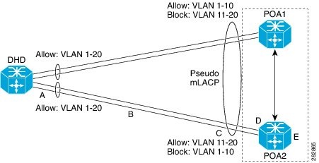
In the illustration, POA ports are configured for a PMLACP role, and ports are configured in active-active mode with manual VLAN load-balancing. The POAs are configured to allow certain VLANs on one of their downlinks but not the other VLANs. The POA activates its uplinks for locally active VLANs. DHD is configured to enable all VLANs on both its uplinks. Traffic from DHD is initially flooded on both uplinks until DHD learns which uplink is active for which VLANs.
Failover Operations
The PMLACP feature provides network resiliency by protecting against port, link, and node failures.
Figure 2-5 explains the failure points in a network.
Figure 2-5
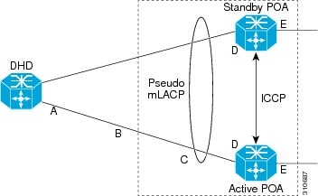
PMLACP Failover Protection
These failures can be categorized into five types.
•![]() A—Failure of the uplink port on the DHD
A—Failure of the uplink port on the DHD
•![]() B—Failure of the ethernet link
B—Failure of the ethernet link
•![]() C—Failure of the downlink port on the POA
C—Failure of the downlink port on the POA
•![]() D—Failure of the POA node
D—Failure of the POA node
•![]() E—Failure of the active POA uplinks
E—Failure of the active POA uplinks
The failover operations are triggered by three different events.
•![]() Access side link or port failure (failure types A- C): PMLACP on the failing POA initiates a failover to the peer for any VLANs that were active on the failed link or links. This failover is initiated by sending an MLACP port state Type Length Value (TLV) message, indicating that the port state is down.
Access side link or port failure (failure types A- C): PMLACP on the failing POA initiates a failover to the peer for any VLANs that were active on the failed link or links. This failover is initiated by sending an MLACP port state Type Length Value (TLV) message, indicating that the port state is down.
•![]() Node failure (failure type D): PMLACP on the surviving POA receives a node failure notification and initiates a failover of all VLANs in standby mode on all shared MLAGs.
Node failure (failure type D): PMLACP on the surviving POA receives a node failure notification and initiates a failover of all VLANs in standby mode on all shared MLAGs.
•![]() POA uplink failure (failure type E): The failing POA sends a message to the peer about the core isolation using the MLACP system state TLV, indicating that the POA is isolated. It will then place all VLANs in the blocking mode.
POA uplink failure (failure type E): The failing POA sends a message to the peer about the core isolation using the MLACP system state TLV, indicating that the POA is isolated. It will then place all VLANs in the blocking mode.
All the three failover events involve the peer POA receiving a notification of the failure. At this point the receiving standby POA completes the following steps:
1. ![]() Unblocks any of the affected VLANs which were in standby or blocked mode.
Unblocks any of the affected VLANs which were in standby or blocked mode.
2. ![]() Sends a MAC flush message to the access side network device through a Multiple VLAN Registration Protocol (MVRP) message. This message reflects all the VLANs which are being activated only for the associated interface. When DHD receives the MVRP message, DHD responds by flushing the MAC address tables for those VLANs.
Sends a MAC flush message to the access side network device through a Multiple VLAN Registration Protocol (MVRP) message. This message reflects all the VLANs which are being activated only for the associated interface. When DHD receives the MVRP message, DHD responds by flushing the MAC address tables for those VLANs.
3. ![]() Triggers the core network edge MAC flushing.
Triggers the core network edge MAC flushing.
Failure Recovery
PMLACP uses revertive mode after a failure recovery to support the active-active model. The reversal process is also similar to the failover process. The standby POA initates the reversal for each VLAN by indicating that the POA is relinquishing its active role for the VLAN. This is done though an ICCP PLACP interface state TLV message, which indicates that it is no longer in active mode for the affected VLANs. Upon TLV receipt, the recovering POA unblocks the affected VLANs and triggers the MAC flushes towards access side and core side.
Revertive mode is enabled by default. If you want to choose when to trigger reversion after the failover recovery, you can configure non revertive mode. The non revertive mode is enabled by configuring the command lacp failover non-revertive under port channel.
Restrictions for PMLACP
Follow this restrictions and usage guidelines while configuring PMLACP.
•![]() PMLACP is supported on ES+ and ES 20 line cards.
PMLACP is supported on ES+ and ES 20 line cards.
•![]() PMLACP is supported on SUP 720 and RSP 720.
PMLACP is supported on SUP 720 and RSP 720.
•![]() PMLACP configuration on a port channel supports only service instances.
PMLACP configuration on a port channel supports only service instances.
•![]() If PMLACP is enabled on a port channel, Resilient Ethernet Protocol (RTP), Spanning Tree Protocol (STP), Link Aggregation Control Protocol (LACP), VLAN Trunking Protocol (VTP), or other layer 2 control protocols are not supported.
If PMLACP is enabled on a port channel, Resilient Ethernet Protocol (RTP), Spanning Tree Protocol (STP), Link Aggregation Control Protocol (LACP), VLAN Trunking Protocol (VTP), or other layer 2 control protocols are not supported.
•![]() The ethernet VLAN color blocking needs to be configured on all VLANs under the port channel if it has EVC xconnect or MTP configured on it. Use the ethernet vlan color-block vlan all command for configuring it.
The ethernet VLAN color blocking needs to be configured on all VLANs under the port channel if it has EVC xconnect or MTP configured on it. Use the ethernet vlan color-block vlan all command for configuring it.
•![]() Both POAs must contain the same configuration of manual-load balance VLAN list and LAG.
Both POAs must contain the same configuration of manual-load balance VLAN list and LAG.
•![]() The bridge-domain that is configured under a PMLACP port channel EVC should not be part of any other non PMLACP interfaces.
The bridge-domain that is configured under a PMLACP port channel EVC should not be part of any other non PMLACP interfaces.
•![]() Only one port channel of MLACP or PMLACP type is supported on a single redundancy group (RG). There can be one MLACP port channel and another PMLACP port channel on a single RG, but not two port channels of the same type.
Only one port channel of MLACP or PMLACP type is supported on a single redundancy group (RG). There can be one MLACP port channel and another PMLACP port channel on a single RG, but not two port channels of the same type.
•![]() Active VLAN list configuration needs to be the same on both POAs.
Active VLAN list configuration needs to be the same on both POAs.
•![]() The port-channel configuration on both POAs must be the same, but port-channel members need not be the same.
The port-channel configuration on both POAs must be the same, but port-channel members need not be the same.
•![]() The recommended configuration sequence for PMLACP is:
The recommended configuration sequence for PMLACP is:
–![]() Configure interchassis group and PMLACP commands.
Configure interchassis group and PMLACP commands.
–![]() Configure MLACP interchassis group and other port channel commands.
Configure MLACP interchassis group and other port channel commands.
–![]() Add member links.
Add member links.
Configuring PMLACP on Cisco 7600
Complete the following steps to configure PMLACP on the Cisco 7600 router.
SUMMARY STEPS
1. ![]() enable
enable
2. ![]() configure terminal
configure terminal
3. ![]() pseudowire-class pw-class-name
pseudowire-class pw-class-name
4. ![]() encapsulation mpls
encapsulation mpls
5. ![]() status peer topology dual-homed
status peer topology dual-homed
6. ![]() exit
exit
7. ![]() l2 vfi name manual
l2 vfi name manual
8. ![]() vpn id vpn-id
vpn id vpn-id
9. ![]() neighbor remote-id encapsulation mpls
neighbor remote-id encapsulation mpls
10. ![]() exit
exit
11. ![]() redundancy
redundancy
12. ![]() interchassis group number
interchassis group number
13. ![]() monitor peer bfd
monitor peer bfd
14. ![]() member IP IP-address
member IP IP-address
15. ![]() mlacp node-id number
mlacp node-id number
16. ![]() mlacp system-priority priority
mlacp system-priority priority
17. ![]() backbone interface interface
backbone interface interface
18. ![]() exit
exit
19. ![]() interface port-channel port-channel number
interface port-channel port-channel number
20. ![]() no ip address
no ip address
21. ![]() mlacp interchassis group group-id
mlacp interchassis group group-id
22. ![]() mlacp mode active-active
mlacp mode active-active
23. ![]() mlacp load-balance primary vlan range
mlacp load-balance primary vlan range
24. ![]() mlacp load-balance secondary vlan range
mlacp load-balance secondary vlan range
25. ![]() ethernet vlan color-block all
ethernet vlan color-block all
26. ![]() service instance id ethernet
service instance id ethernet
27. ![]() encapsulation dot1q vlan id
encapsulation dot1q vlan id
28. ![]() rewrite ingress tag pop {1 | 2} symmetric
rewrite ingress tag pop {1 | 2} symmetric
29. ![]() xconnect peer-id vc-id pw-class pw-class-name
xconnect peer-id vc-id pw-class pw-class-name
or
brige-domain bridge-domain-id
30. ![]() backup peer peer-id vc-id pw-class pw-class-name
backup peer peer-id vc-id pw-class pw-class-name
31. ![]() exit
exit
32. ![]() interface vlan bridge-domain-id
interface vlan bridge-domain-id
33. ![]() xconnect vfi vfi-name
xconnect vfi vfi-name
34. ![]() end
end
DETAILED STEPS
Configuration Examples
This is a configuration example for PMLACP with EVC xconnect on two POAs, A and B. In this example primary VLAN range is configured as 100-109 on router A and 110-120 on router B. The VLAN range is interchanged so that the primary VLAN range of router A becomes the secondary VLAN range in router B and the secondary VLAN range of router A becomes the primary VLAN range in router B.
RouterA> enable
RouterA# configure terminal
RouterA(config)# pseudowire-class vpws
RouterA(config-pw-class)# encapsulation mpls
RouterA(config-pw-class)# status peer topology dual-homed
RouterA(config-pw-class)# exit
RouterA(config)# l2 vfi vpls manual
RouterA(config-vfi)# vpn id 100
RouterA(config-vfi)# neighbor 3.3.3.3 encapsulation mpls
RouterA(config-vfi)# exit
RouterA(config)# redundancy
RouterA(config-red)# interchassis group 100
RouterA(config-r-ic)# monitor peer bfd
RouterA(config-r-ic)# member ip 2.2.2.2
RouterA(config-r-ic)# backbone interface GigabitEthernet8/0/10
RouterA(config-r-ic)# mlacp system-priority 100
RouterA(config-r-ic)# mlacp node-id 1
Router(config)# interface Port-channel10
RouterA(config-if)# no ip address
RouterA(config-if)# mlacp interchassis group 100
RouterA(config-if)# mlacp mode active-active
RouterA(config-if)# mlacp load-balance primary vlan 100-109
RouterA(config-if)# mlacp load-balance secondary vlan 110-120
RouterA(config-if)# ethernet vlan color-block all
RouterA(config-if)# service instance 10 ethernet
RouterA(config-if-srv)# encapsulation dot1q 100
RouterA(config-if-srv)# rewrite ingress tag pop 1 symmetric
RouterA(config-if-srv)# xconnect 3.3.3.3 90 pseudowire-class vpws
RouterA(config-if-srv)# backup peer 4.3.3.3 91
RouterA(config-if)# service instance 11 ethernet
RouterA(config-if-srv)# encapsulation dot1q 101
RouterA(config-if-srv)# rewrite ingress tag pop 1 symmetric
RouterA(config-if-srv)# bridge-domain 201
RouterA(config-if-srv)# exit
RouterA(config-if)# exit
RouterA(config)# interface vlan 201
RouterA(config-if)# no shutdown
RouterA(config-if)# xconnect vfi vpls
RouterA(config-if)# end
RouterB> enable
RouterB# configure terminal
RouterB(config)# pseudowire-class vpws
RouterB(config-pw-class)# encapsulation mpls
RouterB(config-pw-class)# status peer topology dual-homed
RouterB(config-pw-class)# exit
RouterB(config)# l2 vfi vpls manual
RouterB(config-vfi)# vpn id 100
RouterB(config-vfi)# neighbor 3.3.3.3 encapsulation mpls
RouterB(config-vfi)# exit
RouterB(config)# redundancy
RouterB(config-red)# interchassis group 100
RouterB(config-r-ic)# monitor peer bfd
RouterB(config-r-ic)# member ip 1.1.1.1
RouterB(config-r-ic)# backbone interface GigabitEthernet8/0/10
RouterB(config-r-ic)# mlacp system-priority 100
RouterB(config-r-ic)# mlacp node-id 2
Router(config)# interface Port-channel 10
RouterB(config-if)# no ip address
RouterB(config-if)# mlacp interchassis group 100
RouterB(config-if)# mlacp mode active-active
RouterB(config-if)# mlacp load-balance primary vlan 110-120
RouterB(config-if)# mlacp load-balance secondary vlan 100-109
RouterB(config-if)# ethernet vlan color-block all
RouterB(config-if)# service instance 10 ethernet
RouterB(config-if-srv)# encapsulation dot1q 100
RouterB(config-if-srv)# rewrite ingress tag pop 1 symmetric
RouterB(config-if-srv)# xconnect 3.3.3.3 90 pseudowire-class vpws
RouterB(config-if-srv)# backup peer 4.3.3.3 91
RouterB(config-if)# service instance 11 ethernet
RouterB(config-if-srv)# encapsulation dot1q 101
RouterB(config-if-srv)# rewrite ingress tag pop 1 symmetric
RouterB(config-if-srv)# bridge-domain 201
RouterB(config-if-srv)# exit
RouterB(config-if)# exit
RouterB(config)# interface vlan 201
RouterB(config-if)# no shutdown
RouterB(config-if)# xconnect vfi vpls
RouterB(config-if)# end
Verification
Use the show lacp multi-chassis load-balance port-channel number command to verify the PMLACP configuration information on the port channel interface.
PE1# show lacp multi-chassis load-balance port-channel 10
Interface Port-Channel 10
Local Configuration:
P-mLACP Enabled: Yes
Redundancy Group: 100
Revertive Mode: Non-Revertive
Primary VLANs: 4001-4002,4004-4005,4007-4010
Secondary VLANs: 4012-4013,4015-4016,4018-4021
Local Interface State:
Interface ID: 10
Port State: Up
Primary VLAN State: Standby
Secondary VLAN State: Standby
Peer Interface State:
Interface ID: 10
Primary VLAN State: Active
Secondary VLAN State: Active
Use the show lacp multi-chassis group command to display the interchassis redundancy group and the operational LACP parameters.
PE1# show lacp multi-chassis group
Interchassis Redundancy Group 100
Operational LACP Parameters:
RG State: Synchronized
System-Id: 32768.001b.0de6.3080
ICCP Version: 0
Backbone Uplink Status: Connected
Local Configuration:
Node-id: 1
System-Id: 32768.001b.0de6.3080
Peer Information:
State: Up
Node-id: 2
System-Id: 32768.f866.f2d2.6680
ICCP Version: 0
State Flags: Active - A
Standby - S
Down - D
AdminDown - AD
Standby Reverting - SR
Unknown - U
mLACP Channel-groups
Channel State Priority Active Links Inactive Links
Group Local/Peer Local/Peer Local/Peer Local/Peer
10 A/A 32768/32768 2/2 0/0
Redundancy Group 100 (0x64)
Applications connected: mLACP, Pseudo-mLACP
Monitor mode: BFD
member ip: 2.2.2.2 "PE2", CONNECTED
BFD neighbor: GigabitEthernet2/9, next hop 192.168.41.2, UP
mLACP state: CONNECTED
Pseudo-mLACP state: CONNECTED
backbone int GigabitEthernet8/0/9: UP (IP)
ICRM fast-failure detection neighbor table
IP Address Status Type Next-hop IP Interface
========== ====== ==== =========== =========
2.2.2.2 UP BFD 192.168.41.2 GigabitEthernet2/9
Use the show lacp multi-chassis load-balance group command to display the PMLACP configuration information including redundancy group, link states and interface status.
PE2#sh lacp multi-chassis load-balance group
Interchassis Redundancy Group 100
RG State: Synchronized
ICCP Version: 0
Backbone Uplink Status: Connected
Local Configuration:
Node-id: 2
Peer Information:
State: Up
Node-id: 1
ICCP Version: 0
States: Active - ACT Standby - SBY
Down - DN AdminDown - ADN
Unknown - UN Reverting - REV
P-mLACP Interfaces
Interface Port State Local VLAN State Peer VLAN State
ID Local Primary/Secondary Primary/Secondary
10 ADN ADN/ADN DN/DN
34 UP ACT/SBY ACT/SBY
Troubleshooting Tips
Table 2-10 Troubleshooting
Tips
Configuring Custom Ethertype for EVC Interfaces
Custom Ethertype feature allows you to customize the Ethernet settings on an ES20 line card. This feature enables you to configure an ethertype with the outer tag for dot1Q and QinQ packets. Both EVCs (802.1Q and QinQ) and QinQ routed subinterfaces support custom ethertype. By default Cisco 7600 series router supports Ethertype 0x8100 for dot1Q and Q-in-Q outer tag. You can use the custom ethertype feature to configure the following ethertypes for each port on ES20 line cards:
•![]() 0x8100 - 802.1q
0x8100 - 802.1q
•![]() 0x9100 - Q-in-Q
0x9100 - Q-in-Q
•![]() 0x9200 - Q-in-Q
0x9200 - Q-in-Q
•![]() 0x88a8 - 802.1ad
0x88a8 - 802.1ad
Use this command to configure a custom ethertype on a physical port.
dot1q tunneling ethertype <0x88A8 | 0x9100 | 0x9200>
In this sample configuration, Ethertype is set to 0x9100, service instance is created, and rewrite is initiated:
interface GigabitEthernet 1/0/0
dot1q tunneling ethertype 0x9100
service instance <number> ethernet
encapsulation dot1q <vlan 1> [second-dot1q <vlan 2>]
Rewrite <Rewrite>
Note ![]() 802.1q (0x8100) is the default ethertype setting.
802.1q (0x8100) is the default ethertype setting.
Supported Rewrite Rules for a Custom Ethertype Configuration
Rewriting allows you to add or remove VLAN tags in the packets that are transferred between two customer sites within a service provider network.
These rewrites are supported on a Network Network Interface (NNI):
•![]() Non range on C-Tag on an NNI
Non range on C-Tag on an NNI
•![]() Range on C-Tag on an NNI
Range on C-Tag on an NNI
Supported Rewrites for Non Range on a C-Tag on an NNI
When a custom ethertype is configured within the NNI physical interface, and VLAN range is not specified, the following rewrites are supported for a provider bridge:
•![]() For encapsulation untagged:
For encapsulation untagged:
–![]() No rewrite
No rewrite
–![]() Rewrite ingress tag push dot1q vlan1 [second-dot1q vlan2] symmetric
Rewrite ingress tag push dot1q vlan1 [second-dot1q vlan2] symmetric
•![]() For encapsulation default:
For encapsulation default:
–![]() No rewrite
No rewrite
•![]() For encapsulation dot1q vlan:
For encapsulation dot1q vlan:
–![]() No rewrite
No rewrite
–![]() Rewrite ingress tag pop 1 symmetric
Rewrite ingress tag pop 1 symmetric
–![]() Rewrite ingress tag translates 1-to-1 dot1q vlan symmetric
Rewrite ingress tag translates 1-to-1 dot1q vlan symmetric
–![]() Rewrite ingress tag translate 1-to-2 dot1q vlan 1 second-dot1q vlan 2 symmetric
Rewrite ingress tag translate 1-to-2 dot1q vlan 1 second-dot1q vlan 2 symmetric
•![]() For encapsulation dot1q vlan1 second-dot1q vlan2
For encapsulation dot1q vlan1 second-dot1q vlan2
–![]() No rewrite
No rewrite
–![]() Rewrite ingress tag pop 1 symmetric
Rewrite ingress tag pop 1 symmetric
–![]() Rewrite ingress tag pop 2 symmetric
Rewrite ingress tag pop 2 symmetric
–![]() Rewrite ingress tag translate 1-to-1 dot1q vlan symmetric
Rewrite ingress tag translate 1-to-1 dot1q vlan symmetric
–![]() Rewrite ingress tag translate 1-to-2 dot1q vlan 1 second dot1q vlan 2 symmetric
Rewrite ingress tag translate 1-to-2 dot1q vlan 1 second dot1q vlan 2 symmetric
–![]() Rewrite ingress tag translate 2-to-1 dot1q vlan symmetric
Rewrite ingress tag translate 2-to-1 dot1q vlan symmetric
–![]() Rewrite ingress tag translate 2-to-2 dot1q vlan 1 second-dot1q vlan 2 symmetric
Rewrite ingress tag translate 2-to-2 dot1q vlan 1 second-dot1q vlan 2 symmetric
Supported Rewrites for Range on C-Tag with an NNI
When a VLAN range is specified on the C-Tag, push Rewrites are not supported. These rewrites are supported for a VLAN range on C-Tag:
•![]() For encapsulation dot1q vlan1 - vlan2:
For encapsulation dot1q vlan1 - vlan2:
–![]() No rewrite
No rewrite
•![]() For encapsulation dot1q vlan1 second-dot1q vlan2 - vlan3:
For encapsulation dot1q vlan1 second-dot1q vlan2 - vlan3:
–![]() No rewrite
No rewrite
–![]() Rewrite ingress tag pop 1 symmetric
Rewrite ingress tag pop 1 symmetric
–![]() Rewrite ingress tag translate 1-to-1 dot1q vlan symmetric
Rewrite ingress tag translate 1-to-1 dot1q vlan symmetric
–![]() Rewrite ingress tag translate 1-to-2 dot1q vlan 1 second-dot1q vlan 2 symmetric
Rewrite ingress tag translate 1-to-2 dot1q vlan 1 second-dot1q vlan 2 symmetric
Note ![]() To avoid hierarchical provider bridges during custom ethertype configuration, NNI interface does not support ingress push rewrite except for encap untagged.
To avoid hierarchical provider bridges during custom ethertype configuration, NNI interface does not support ingress push rewrite except for encap untagged.
Restrictions and Usage Guidelines
Follow these restrictions and usage guidelines while configuring custom ethertype:
•![]() Cisco IOS Release 15.1(1)S supports custom ethertype on port-channels.
Cisco IOS Release 15.1(1)S supports custom ethertype on port-channels.
•![]() Custom ethertype is configured within a physical interface and is applicable to all service instances and subinterfaces of the physical interface.
Custom ethertype is configured within a physical interface and is applicable to all service instances and subinterfaces of the physical interface.
•![]() Mixed custom ethertype is not supported. If you configure the ingress interface values as 8100/9100/9200/88a8, then traffic other than the corresponding ethertype in the outer tag is not supported. If a packet is received with outer-tag other than the configured custom ethertype, then it is treated as untagged. However, when a packet with outer tag 8100 is received, it is treated as tagged packet, irrespective of the configured custom ethertype.
Mixed custom ethertype is not supported. If you configure the ingress interface values as 8100/9100/9200/88a8, then traffic other than the corresponding ethertype in the outer tag is not supported. If a packet is received with outer-tag other than the configured custom ethertype, then it is treated as untagged. However, when a packet with outer tag 8100 is received, it is treated as tagged packet, irrespective of the configured custom ethertype.
•![]() When a custom ethertype is configured on the egress port with connect/cross connect configuration, the egress port does not filter the VLAN, and mismatched VLANs are relayed through the egress port.
When a custom ethertype is configured on the egress port with connect/cross connect configuration, the egress port does not filter the VLAN, and mismatched VLANs are relayed through the egress port.
•![]() If a custom ethertype is configured on the port-channel, the same ethertype is implicitly configured for all the other member interfaces.
If a custom ethertype is configured on the port-channel, the same ethertype is implicitly configured for all the other member interfaces.
•![]() You cannot configure custom ethertype explicitly under a member interface of a port-channel.
You cannot configure custom ethertype explicitly under a member interface of a port-channel.
•![]() An interface configured with custom ethertype cannot be a part of port-channel.
An interface configured with custom ethertype cannot be a part of port-channel.
This example shows ingress and egress port configuration:
Ingress configuration
Int Gi1/1
Dot1q tunnel ethertype 0x9100
service instance 1 ethernet
Encap dot1q [second-dot1q]
Egress configuration
Int Gi1/1
Dot1q tunneling ethertype 0x9200
service instance 1 eth
Encap untagged
SUMMARY STEPS
1. ![]() enable
enable
2. ![]() configure terminal
configure terminal
3. ![]() interface gigabitethernet {ethernet |tengigabit Ethernet}
interface gigabitethernet {ethernet |tengigabit Ethernet}
4. ![]() dot1q tunneling ethertype [0x9100| 0x9200| 0x88A8]
dot1q tunneling ethertype [0x9100| 0x9200| 0x88A8]
5. ![]() service instance Ethernet id [Ethernet service name]
service instance Ethernet id [Ethernet service name]
6. ![]() [no] encapsulation untagged, dot1q {any | vlan-id[vlan-id[vlan-id]} second-dot1q {any | vlan-id[vlan-id[vlan-id]]}
[no] encapsulation untagged, dot1q {any | vlan-id[vlan-id[vlan-id]} second-dot1q {any | vlan-id[vlan-id[vlan-id]]}
7. ![]() Rewrite ingress tag {push {dot1q vlan-id | dot1q vlan-id second-dot1q vlan-id dot1q vlan-id} | pop {1 | 2} | translate {1-to-1 {dot1q vlan-id}| 2-to-1 dot1q vlan-id }| 1-to-2 {dot1q vlan-id second-dot1q vlan-id dot1q vlan-id} | 2-to-2 {dot1q vlan-id second-dot1q vlan-id dot1q vlan-id}} symmetric
Rewrite ingress tag {push {dot1q vlan-id | dot1q vlan-id second-dot1q vlan-id dot1q vlan-id} | pop {1 | 2} | translate {1-to-1 {dot1q vlan-id}| 2-to-1 dot1q vlan-id }| 1-to-2 {dot1q vlan-id second-dot1q vlan-id dot1q vlan-id} | 2-to-2 {dot1q vlan-id second-dot1q vlan-id dot1q vlan-id}} symmetric
8. ![]() exit
exit
DETAILED STEPS
Examples
Single Tag Encap with Connect with Custom Ethertype Configured
In this example, custom ethertype is configured on a single tag encap using the connect configuration:
Router#sh running-config int Gi1/0/0
//Building configuration...
interface GigabitEthernet1/0/0
no ip address
dot1q tunneling ethertype 0x9100
no mls qos trust
service instance 1 ethernet
encapsulation dot1q 10
interface GigabitEthernet1/0/2
no ip address
dot1q tunneling ethertype 0x9100
mls qos trust dscp
service instance 1 ethernet
encapsulation dot1q 10
Router)#connect LC1 GigabitEthernet 1/0/0 1 GigabitEthernet 1/0/2 1
Single Tag Encap with Bridge Domain
In this example, custom ethertype is configured on a single tag encap using bridge domain configuration:
interface GigabitEthernet1/0/0
no ip address
dot1q tunneling ethertype 0x9100
no mls qos trust
service instance 1 ethernet
encapsulation dot1q 10
bridge-domain 100
interface GigabitEthernet1/0/2
no ip address
dot1q tunneling ethertype 0x9100
mls qos trust dscp
service instance 1 ethernet
encapsulation dot1q 10
bridge-domain 100
Single Tag Encap with Cross Connect
In this example, custom ethertype is configured on a single tag encap with cross connect configuration:
interface GigabitEthernet1/0/0
no ip address
dot1q tunneling ethertype 0x9100
no mls qos trust
service instance 1 ethernet
encapsulation dot1q 10
xconnect 3.3.3.3 10 encapsulation mpls
interface GigabitEthernet1/0/1
ip address 10.10.10.2 255.255.255.0
no mls qos trust
mpls label protocol ldp
mpls ip
Custom Ethertype Support with Sub Interfaces
In this example, custom ethertype is configured on a subinterface. Custom ethertype is always configured within the main physical interface and QinQ encap is configured within the subinterface.
interface GigabitEthernet1/0/0
no ip address
dot1q tunneling ethertype 0x9100
no mls qos trust
end
interface GigabitEthernet1/0/0.10
encapsulation dot1Q 10 second-dot1q 20
ip address 20.20.20.2 255.255.255.0
end
Verification
Use these commands to verify operations.
Configuring Flexible QinQ Mapping and Service Awareness on 7600-ESM-2X10GE and 7600-ESM-20X1GE
The Flexible QinQ Mapping and Service Awareness on 7600-ESM-2X10GE and 7600-ESM-20X1GE feature allows service providers to offer triple-play services, residential internet access from a DSLAM, and business Layer 2 and Layer 3 VPN by providing for termination of double-tagged dot1q frames onto a Layer 3 subinterface at the access node.
The access node connects to the DSLAM through the 7600-ESM-2X10GE or 7600-ESM-20X1GE. This provides a flexible way to identify the customer instance by its VLAN tags, and to map the customer instance to different services.
Flexible QinQ Mapping and Service Awareness on 7600-ESM-2X10GE and 7600-ESM-20X1GE is supported only through Ethernet Virtual Connection Services (EVCS) service instances.
EVCS uses the concepts of EVCs (Ethernet virtual circuits) and service instances. An EVC is an end-to-end representation of a single instance of a Layer 2 service being offered by a provider to a customer. It embodies the different parameters on which the service is being offered. A service instance is the instantiation of an EVC on a given port on a given router.
Figure 2-6 shows a typical metro architecture where the access switch facing the DSLAM provides VLAN translation (selective QinQ) and grooming functionality and where the service routers (SR) provide QinQ termination into a Layer 2 or Layer 3 service.
Figure 2-6
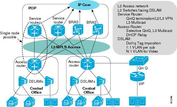
Flexible QinQ Mapping and Service Awareness on 7600-ESM-2X10GE and 7600-ESM-20X1GE provides the following functionality:
•![]() VLAN connect with local significance (VLAN local switching)
VLAN connect with local significance (VLAN local switching)
–![]() Single tag Ethernet local switching where the received dot1q tag traffic from one port is cross connected to another port by changing the tag. This is a 1-to-1 mapping service and there is no MAC learning involved.
Single tag Ethernet local switching where the received dot1q tag traffic from one port is cross connected to another port by changing the tag. This is a 1-to-1 mapping service and there is no MAC learning involved.
–![]() Double tag Ethernet local switching where the received double tag traffic from one port is cross connected to another port by changing both tags. The mapping to each double tag combination to the cross-connect is 1-to-1. There is no MAC learning involved.
Double tag Ethernet local switching where the received double tag traffic from one port is cross connected to another port by changing both tags. The mapping to each double tag combination to the cross-connect is 1-to-1. There is no MAC learning involved.
–![]() Hairpinning:is a cross connect between two EFPS on the same port.
Hairpinning:is a cross connect between two EFPS on the same port.
•![]() Selective QinQ (1-to-2 translation)
Selective QinQ (1-to-2 translation)
–![]() Cross connect—Selective QinQ adds an outer tag to the received dot1q traffic and then tunnels it to the remote end with Layer 2 switching or EoMPLS.
Cross connect—Selective QinQ adds an outer tag to the received dot1q traffic and then tunnels it to the remote end with Layer 2 switching or EoMPLS.
•![]() Double tag translation (2-to-2 translation) Layer 2 switching— Two received tagged frames are popped and two new tags are pushed.
Double tag translation (2-to-2 translation) Layer 2 switching— Two received tagged frames are popped and two new tags are pushed.
–![]() Cross connect—Selective QinQ adds an outer tag to the received dot1q traffic and then tunnels it to the remote end with Layer 2 switching or EoMPLS.
Cross connect—Selective QinQ adds an outer tag to the received dot1q traffic and then tunnels it to the remote end with Layer 2 switching or EoMPLS.
–![]() Layer 2 switching—Selective QinQ adds an outer tag to the received dot1q traffic and then performs Layer 2 switching to allow SVI based on the outer tag for configuring additional services.
Layer 2 switching—Selective QinQ adds an outer tag to the received dot1q traffic and then performs Layer 2 switching to allow SVI based on the outer tag for configuring additional services.
•![]() Double tag translation (2-to-2 translation) Layer 2 switching— Two received tagged frames are popped and two new tags are pushed.
Double tag translation (2-to-2 translation) Layer 2 switching— Two received tagged frames are popped and two new tags are pushed.
•![]() Double tag termination (2-to-1 tag translation)
Double tag termination (2-to-1 tag translation)
–![]() Ethernet MultiPoint Bridging over Ethernet (MPBE)—The incoming double tag is uniquely mapped to a single dot1q tag that is then used to do MPBE
Ethernet MultiPoint Bridging over Ethernet (MPBE)—The incoming double tag is uniquely mapped to a single dot1q tag that is then used to do MPBE
–![]() Double tag MPBE—The ingress line uses double tags in the ingress packet to look up the bridging VLAN. The double tags are popped and the egress line card adds new double tags and sends the packet out.
Double tag MPBE—The ingress line uses double tags in the ingress packet to look up the bridging VLAN. The double tags are popped and the egress line card adds new double tags and sends the packet out.
–![]() Double tag routing—Same as regular dot1q tag routing except that double tags are used to identify the hidden VLAN.
Double tag routing—Same as regular dot1q tag routing except that double tags are used to identify the hidden VLAN.
•![]() Local VLAN significance—VLAN tags are significant only to the port.
Local VLAN significance—VLAN tags are significant only to the port.
•![]() Scalable EoMPLS VC—Single tag packets are sent across the tunnel.
Scalable EoMPLS VC—Single tag packets are sent across the tunnel.
•![]() QinQ policing and QoS
QinQ policing and QoS
•![]() Layer 2 protocol data unit (PDU) packet—If the Layer 2 PDUs are tagged, packets are forwarded transparently; if the Layer 2 PDUs are untagged, packets are treated per the physical port configuration.
Layer 2 protocol data unit (PDU) packet—If the Layer 2 PDUs are tagged, packets are forwarded transparently; if the Layer 2 PDUs are untagged, packets are treated per the physical port configuration.
Restrictions and Usage Guidelines
When configuring Flexible QinQ Mapping and Service Awareness on 7600-ESM-2X10GE and 7600-ESM-20X1GE, follow these restrictions and usage guidelines:
•![]() Service Scalability:
Service Scalability:
–![]() Service Instances per port / NP: 8, 000
Service Instances per port / NP: 8, 000
–![]() Service instances per Line Card: 16, 000
Service instances per Line Card: 16, 000
–![]() Service instances per port-channel: 8000. This is subject to the number of members per NP. This value would reduce by the factor of the member links per NP. If the members links are spread across various NPs, then the max number of service instances per port channel is unchanged.
Service instances per port-channel: 8000. This is subject to the number of members per NP. This value would reduce by the factor of the member links per NP. If the members links are spread across various NPs, then the max number of service instances per port channel is unchanged.
–![]() TCAM Entry Usage: The number of TCAMs an EVC uses depends on the encapsulation configured on the TCAM as shown in the following examples.
TCAM Entry Usage: The number of TCAMs an EVC uses depends on the encapsulation configured on the TCAM as shown in the following examples.
Example 1
service instance 1 eth
encap dot1q 100
TCAMS used - 1
Example 2
service instance 1 eth
encap dot1q 200 second dot1q 300
TCAMs used - 1
Example 3
service instance 1 eth
encap dot1q 201, 202
TCAMs used - 2 (one for each encapsulation)
Example 4
service instance 1 eth
encap dot1q 20-40
TCAMs used - 4
First entry to match vlans 20-23
Second entry to match vlans 24-31
Third entry to match vlans 32-39
Fourth entry to match vlan 40
A range does not always mean multiple TCAMs as shown in the following example where one TCAM entry is used.
Example 5 -
service instance 1 ethernet
encap dot1q 8-15
service instance 2 ethernet
encap dot1q 2000 second-dot1q 96-127
TCAM usage per EVC : 1
–![]() Service instances per router: 32, 000
Service instances per router: 32, 000
–![]() Bridge-domains per router: 4, 000
Bridge-domains per router: 4, 000
–![]() Local switching: 16, 000
Local switching: 16, 000
–![]() Xconnect: 16, 000
Xconnect: 16, 000
–![]() Subinterface: 2, 000
Subinterface: 2, 000
–![]() Number of service instance on a particular domain: 110 per NP
Number of service instance on a particular domain: 110 per NP
•![]() QoS Scalability:
QoS Scalability:
–![]() Shaping - parent queue is 2,000 and child queue is 16,000
Shaping - parent queue is 2,000 and child queue is 16,000
–![]() Marking - parent queue is 2,000 and child queue is 16,000
Marking - parent queue is 2,000 and child queue is 16,000
•![]() Modular QoS CLI (MQC) actions supported include:
Modular QoS CLI (MQC) actions supported include:
–![]() Shaping
Shaping
–![]() Bandwidth
Bandwidth
–![]() Two priority queues per policy
Two priority queues per policy
–![]() The set cos command, set cos-inner command, set cos cos-inner command, and set cos-inner cos command
The set cos command, set cos-inner command, set cos cos-inner command, and set cos-inner cos command
–![]() WRED aggregate
WRED aggregate
–![]() Queue-limit
Queue-limit
SUMMARY STEPS
1. ![]() enable
enable
2. ![]() configure terminal
configure terminal
3. ![]() interface gigabitethernet slot/subslot/port[.subinterface-number] or interface tengigabitethernet slot/subslot/port[.subinterface-number]
interface gigabitethernet slot/subslot/port[.subinterface-number] or interface tengigabitethernet slot/subslot/port[.subinterface-number]
4. ![]() [no] service instance id {Ethernet service-name}
[no] service instance id {Ethernet service-name}
5. ![]() encapsulation dot1q vlan-id
encapsulation dot1q vlan-id
6. ![]() rewrite ingress tag {push {dot1q vlan-id | dot1q vlan-id second-dot1q vlan-id | dot1ad vlan-id dot1q vlan-id} | pop {1 | 2} | translate {1-to-1 {dot1q vlan-id | dot1ad vlan-id}| 2-to-1 dot1q vlan-id | dot1ad vlan-id}| 1-to-2 {dot1q vlan-id second-dot1q vlan-id | dot1ad vlan-id dot1q vlan-id} | 2-to-2 {dot1q vlan-id second-dot1q vlan-id | dot1ad vlan-id dot1q vlan-id}} [symmetric]
rewrite ingress tag {push {dot1q vlan-id | dot1q vlan-id second-dot1q vlan-id | dot1ad vlan-id dot1q vlan-id} | pop {1 | 2} | translate {1-to-1 {dot1q vlan-id | dot1ad vlan-id}| 2-to-1 dot1q vlan-id | dot1ad vlan-id}| 1-to-2 {dot1q vlan-id second-dot1q vlan-id | dot1ad vlan-id dot1q vlan-id} | 2-to-2 {dot1q vlan-id second-dot1q vlan-id | dot1ad vlan-id dot1q vlan-id}} [symmetric]
DETAILED STEPS
Examples
Single Tag VLAN Connect
The following example shows a typical configuration of a DSLAM facing port of the first PE router.
! DSLAM facing port
Router(config)# interface TenGigabitEthernet1/0/1
Router(config-if)# service instance 100 ethernet
Router(config-if-srv)# encapsulation dot1q 10
Router(config-if-srv)# rewrite ingress tag pop 1 symmetric
!L2 facing port
Router(config)# interface TenGigabitEthernet1/0/2
Router(config-if)# service instance 101 ethernet
Router(config-if-srv)# encapsulation dot1q 11
Router(config-if-srv)# rewrite ingress tag pop 1 symmetric
! connect service
Router# connect EVC1 TenGigabitEthernet1/0/1 100 TenGigabitEthernet1/0/2 101
Double Tag VLAN Connect
In this example, an incoming frame with an outer dot1q tag of 10 and inner tag of 20 enters TenGigabitEthernet1/0/1. It is index directed to TenGigabitEthernet1/0/2 and exits with an outer dot1q tag of 11 and inner tag 21. No MAC learning is involved.
The following example shows a typical configuration of a MPLS core facting port of the first PE router.
! DSLAM facing port
Router(config)# interface TenGigabitEthernet1/0/1
Router(config-if)# service instance 100 ethernet
Router(config-if-srv)# encapsulation dot1q second-dot1q 20
Router(config-if-srv)# rewrite ingress tag pop 2 symmetric
!L2 facing port
Router(config)# interface TenGigabitEthernet1/0/2
Router(config-if)# service instance 101 ethernet
Router(config-if-srv)# encapsulation dot1q 11 second-dot1q 21
Router(config-if-srv)# rewrite ingress tag pop 2 symmetric
! connect service
Router# connect EVC1 TenGigabitEthernet1/0/1 100 TenGigabitEthernet1/0/2 101
Selective QinQ with Connect
This configuration uses EoMPLS to perform packet forwarding. This is index directed.
! DSLAM facing port - single tag packet from link
Router(config)# interface TenGigabitEthernet1/0/1
Router(config-if)# service instance 100 ethernet
Router(config-if-srv)# encapsulation dot1q 10-20,30,50-60
!L2/QinQ facing port double tag packets
Router(config)# interface TenGigabitEthernet1/0/2
Router(config-if)# service instance 101 ethernet
Router(config-if-srv)# encapsulation dot1q 11 second-dot1q any
Router(config-if-srv)# rewrite ingress tag pop 1 symmetric
! connecting service instances
! QinQ outer dot1q is 11
Router# connect EVC1 TenGigabitEthernet1/0/1 100 TenGigabitEthernet1/0/2 101
Selective QinQ with Xconnect
This configuration uses EoMPLS under single tag subinterface to perform packet forwarding. The following example shows a typical configuration of a MPLS core facing port of the second PE router.
DSLAM facing port
! DSLAM facing port
Router(config)# interface TenGigabitEthernet1/0/1
Router(config-if)# service instance 100 ethernet
Router(config-if-srv)# encapsulation dot1q 10-20,30,50-60
Router(config-if-srv)# xconnect 2.2.2.2 999 pw-class vlan-xconnect
!
Router(config)# interface Loopback1
Router(config-if)# ip address 1.1.1.1 255.255.255.255
MPLS core facing port
! MPLS core facing port
Router(config)# interface TenGigabitEthernet2/0/1
Router(config-if)# ip address 192.168.1.1 255.255.255.0
Router(config-if)# mpls ip
Router(config-if)# mpls label protocol ldp
!
Router(config)# interface Loopback1
Router(config-if)# ip address 2.2.2.2 255.255.255.255
CE facing EoMPLS configuration
Router(config)# interface TenGigabitEthernet1/0/2
Router(config-if)# service instance 1000
Router(config-if-srv)# encapsulation dot1q 1000 second-dot1q any
Router(config-if-srv)# rewrite ingress tag pop 1 symmetric
Router(config-if-srv)#xconnect 1.1.1.1 999 pw-class vlan-xconnect
Selective QinQ with Layer 2 Switching
This configuration uses Layer 2 Switching to perform packet forwarding. The forwarding mechanism is the same as MPB-E, only the rewrites for each service instance are different.
DSLAM facing port, single tag incoming
Router(config)# interface TenGigabitEthernet1/0/1
Router(config-if)# service instance 100 ethernet
Router(config-if-srv)# encapsulation dot1q 10-20
Router(config-subif)# bridge-domain 11
QinQ VLAN
Router(config)# interface VLAN11
!QinQ facing port
Router(config)# interface TenGigabitEthernet1/0/2
Router(config-if)# switchport
Router(config-if)# switchport mode trunk
Router(config-if)# switchport trunk vlan allow 11
Double Tag Translation (2-to-2 Tag Translation)
In this case, double-tagged frames are received on ingress. Both tags are popped and two new tags are pushed. The packet is then Layer 2 switched to the bridge-domain VLAN.
QinQ facing port
Router(config)# interface TenGigabitEthernet1/0/1
Router(config-if)# service instance 100 ethernet
Router(config-if-srv)# encapsulation dot1q 100 second-dot1q 10
Router(config-if-srv)# rewrite ingress tag translate 2-to-2 dot1q 200 second-dot1q 20
second-dot1q 10
Router(config-subif)# bridge-domain 200
QinQ VLAN
Router(config)# interface VLAN200
!
Router(config)# interface TenGigabitEthernet1/0/2
Router(config-if)# service instance 101 ethernet
Router(config-if-srv)# encapsulation dot1q 200 second-dot1q 20
Router(config-subif)# bridge-domain 200
Double Tag Termination (2 to 1 Tag Translation)
This example falls under the Layer 2 switching case.
Double tag traffic
Router(config)# interface TenGigabitEthernet1/0/1
Router(config-if)# service instance 100 ethernet
Router(config-if-srv)# encapsulation dot1q 200 second-dot1q 20
Router(config-if-srv)# rewrite ingress tag pop 2 symmetric
Router(config-subif)# bridge-domain 10
!
Router(config)# interface TenGigabitEthernet1/0/2
Router(config-if)# service instance 101 ethernet
Router(config-if-srv)# encapsulation dot1q 10
Router(config-if-srv)# rewrite ingress tag pop 1 symmetric
Router(config-subif)# bridge-domain 10
!
Router(config)# interface TenGigabitEthernet1/0/3
Router(config-if)# service instance 101 ethernet
Router(config-if-srv)# encapsulation dot1q 30
Router(config-if-srv)# rewrite ingress tag pop 1 symmetric
Router(config-subif)# bridge-domain 10
Verification
Use the following commands to verify operation.
Troubleshooting
Use these debug commands to troubleshoot Flexible QinQ feature.
Debug commands
Table 2-11 provides the troubleshooting solutions for the Flexible mapping feature.
Table 2-11
Troubleshooting Flexible mapping feature
Configuring Flexible Service Mapping Based on CoS and Ethertype
The Flexible Serivce Mapping based on CoS and Etherytpe feature enhances the current capability of mapping packets to service instance. It uses CoS and Ethertypes to classify traffic into different service instances and consumes less number of VLANs on the module.
Prior to the implementation of this feature, three different VLANs were required to relay voice, data, and video services. This feature distinguishes an EVC based on the CoS value, and implements one EVC with CoS, and another EVC with inner CoS. You can also use the same VLANs for eight different EVCs (CoS values 0-7 = 8 values) saving the usage of VLANs . These EVCs are associated with bridge domain, cross connect (xconnect), and connect.
This feature extends the following capabilities to the current implementation of mapping the service instances:
•![]() Match on a single CoS value (either inner CoS or outer CoS, but not both simultaneously, and applicable only for QinQ).
Match on a single CoS value (either inner CoS or outer CoS, but not both simultaneously, and applicable only for QinQ).
•![]() Match on a range or list of CoS values when a single VLAN is specified in the encapsulation criteria in dot1q/QinQ EVCs.
Match on a range or list of CoS values when a single VLAN is specified in the encapsulation criteria in dot1q/QinQ EVCs.
•![]() Match support for a single CoS value for a range or list of VLANs. Acceptable range of CoS value is 0-7.
Match support for a single CoS value for a range or list of VLANs. Acceptable range of CoS value is 0-7.
•![]() Match the following supported payload ethertypes
Match the following supported payload ethertypes
–![]() IPv4 (etype 0x0800)
IPv4 (etype 0x0800)
–![]() IPv6 (etype 0x086dd)
IPv6 (etype 0x086dd)
–![]() pppoe-all (0x8863 and 0x8864)
pppoe-all (0x8863 and 0x8864)
•![]() In the case of QinQ, inner VLAN can have a range when the outer VLAN is a single VLAN.
In the case of QinQ, inner VLAN can have a range when the outer VLAN is a single VLAN.
•![]() Match on range or list of CoS values when both outer and inner VLANs are single.
Match on range or list of CoS values when both outer and inner VLANs are single.
•![]() Match on ethertype is supported both in the case of a single VLAN or in QinQ.
Match on ethertype is supported both in the case of a single VLAN or in QinQ.
•![]() Supports pppoe-all command (matches both 0x8863 and 0x8864).
Supports pppoe-all command (matches both 0x8863 and 0x8864).
•![]() Matching on pppoe-session and pppoe-discovery commands are individually not supported.
Matching on pppoe-session and pppoe-discovery commands are individually not supported.
You can use CoS and ethertype to classify the traffic into various service instances to reduce the number of vlans.
Restrictions and Usage Guidelines
When configuring Flexible Service Mapping based on CoS and Ethertype, follow these restrictions and guidelines:
•![]() This release supports pppoe-all (matches both pppoe-discovery and pppoe-session), and does not individually support pppoe-discovery and pppoe-session as ethertypes.
This release supports pppoe-all (matches both pppoe-discovery and pppoe-session), and does not individually support pppoe-discovery and pppoe-session as ethertypes.
•![]() This feature supports both Dot1Q and QinQ.
This feature supports both Dot1Q and QinQ.
•![]() Egress behavior implemented for mismatched CoS and Ethertype forwards the packet without re-write. There is no filtering on egress, based on the CoS or Layer 3 Ethertype. Even if CoS or Etherype mismatches, if egress VLAN information matches, the frames are forwarded.
Egress behavior implemented for mismatched CoS and Ethertype forwards the packet without re-write. There is no filtering on egress, based on the CoS or Layer 3 Ethertype. Even if CoS or Etherype mismatches, if egress VLAN information matches, the frames are forwarded.
•![]() Neither pppoe-discovery or pppoe-session are supported individually as Ethertypes. Cisco IOS 12.2(33) SRE release supports pppoe-all.
Neither pppoe-discovery or pppoe-session are supported individually as Ethertypes. Cisco IOS 12.2(33) SRE release supports pppoe-all.
•![]() Service instances on port-channels are supported.
Service instances on port-channels are supported.
•![]() You cannot match Etherype and CoS for the same service instance.
You cannot match Etherype and CoS for the same service instance.
•![]() In the case of QinQ, a service instance can match on either outer Cos or inner Cos, but not simultaneously for the same service instance.
In the case of QinQ, a service instance can match on either outer Cos or inner Cos, but not simultaneously for the same service instance.
•![]() You cannot specify a range or list of outer VLANs in double-tag cases.
You cannot specify a range or list of outer VLANs in double-tag cases.
•![]() MAC learning occurs with bridge-domain, but does not occur with xconnect and connect.
MAC learning occurs with bridge-domain, but does not occur with xconnect and connect.
•![]() Egress checking of VLAN matching does not occur with xconnect and local connect.
Egress checking of VLAN matching does not occur with xconnect and local connect.
Summary Steps
1. ![]() enable
enable
2. ![]() configure terminal
configure terminal
3. ![]() interface gigabitethernet slot/subslot/port or interface tengigabitethernet slot/subslot/port or interface port-channel number
interface gigabitethernet slot/subslot/port or interface tengigabitethernet slot/subslot/port or interface port-channel number
4. ![]() [no] shut
[no] shut
5. ![]() service instance id {Ethernet [service-name]}
service instance id {Ethernet [service-name]}
6. ![]() encapsulation dot1q vlan-id {cos | comma| hyphen| etype} or encapsulation dot1q vlan-id second-dot1q {any | vlan-id[vlan-id[vlan-id]]} or
encapsulation dot1q vlan-id {cos | comma| hyphen| etype} or encapsulation dot1q vlan-id second-dot1q {any | vlan-id[vlan-id[vlan-id]]} or
7. ![]() encapsulation dot1q vlan-id cos [0-7] or encapsulation dot1q vlan-id etype [IPv4|IPv6|pppoe-all] or
encapsulation dot1q vlan-id cos [0-7] or encapsulation dot1q vlan-id etype [IPv4|IPv6|pppoe-all] or
8. ![]() encapsulation dot1Q vlan-id {vlan id} second-dot1q {{any | vlan-id[vlan-id[vlan-id]} } cos {0-7} or
encapsulation dot1Q vlan-id {vlan id} second-dot1q {{any | vlan-id[vlan-id[vlan-id]} } cos {0-7} or
9. ![]() encapsulation dot1Q vlan-id {vlan id} second-dot1q {{any | vlan-id[vlan-id[vlan-id]} } etype {etype string} or
encapsulation dot1Q vlan-id {vlan id} second-dot1q {{any | vlan-id[vlan-id[vlan-id]} } etype {etype string} or
10. ![]() encapsulation dot1Q vlan-id {vlan id} cos [0-7] second-dot1q {{any | vlan-id[vlan-id[vlan-id]} }
encapsulation dot1Q vlan-id {vlan id} cos [0-7] second-dot1q {{any | vlan-id[vlan-id[vlan-id]} }
DETAILED STEPS
Support Configurations
The following are the supported Ethertype and CoS configurations:
Supported payload ethertype configurations for a single tag:
Router(config)# interface gigabitethernet 1/1
Router(config-if)# service instance 1 ethernet
Router(config-if-srv)# encapsulation dot1q vlan id etype ipv4
Supported payload Ethertype configurations for a double tag:
Router(config)# interface gigabitethernet 1/1
Router(config-if)# service instance 1 ethernet
Router(config-if-srv)# encapsulation dot1q vlan id second-dot1q vlan id etype ipv4
Supported payload Ethertype configurations for a single tag with a single VLAN:
Router(config)# interface gigabitethernet 1/1
Router(config-if)# service instance 1 ethernet
Router(config-if-srv)# encapsulation dot1q 10 etype ipv4
Router(config-if-srv)# exit
Router(config-if)# service instance 2 ethernet
Router(config-if-srv)# encapsulation dot1q 10 etype ipv6
Router(config-if-srv)# exit
Router(config-if)# service instance 3 ethernet
Router(config-if-srv)# encapsulation dot1q 10 etype pppoe-all
Supported payload Ethertype configurations for a single tag with range of VLANs:
Router(config)# interface gigabitethernet 1/1
Router(config-if)# service instance 1 ethernet
Router(config-if-srv)# encapsulation dot1q 11-15 etype ipv4
Router(config-if-srv)# exit
Router(config-if)# service instance 2 ethernet
Router(config-if-srv)# encapsulation dot1q 11-15 etype ipv6
Router(config-if-srv)# exit
Router(config-if)# service instance 3 ethernet
Router(config-if-srv)# encapsulation dot1q 11-15 etype pppoe-all
Supported payload Ethertype configurations for a double tag with no range:
Router(config)# interface gigabitethernet 1/1
Router(config-if)# service instance 1 ethernet
Router(config-if-srv)# encapsulation dot1q 10 second-dot1q 1001 etype ipv4
Router(config-if-srv)# exit
Router(config-if)# service instance 2 ethernet
Router(config-if-srv)# encapsulation dot1q 10 second-dot1q 1001 etype ipv6
Router(config-if-srv)# exit
Router(config-if)# service instance 3 ethernet
Router(config-if-srv)# encapsulation dot1q 10 second-dot1q 1001 etype pppoe-all
Supported payload Ethertype configurations for double tag with range on inner VLANs:
Router(config)# interface gigabitethernet 1/1
Router(config-if)# service instance 1 ethernet
Router(config-if-srv)# encapsulation dot1q 10 second-dot1q 11-15 etype ipv4
Router(config-if-srv)# exit
Router(config-if-srv)# encapsulation dot1q 10 second-dot1q 11-15 etype ipv6
Router(config-if-srv)# exit
Router(config-if-srv)# encapsulation dot1q 10 second-dot1q 11-15 etype pppoe-all
Supported CoS configurations for a single tag:
Router(config)# interface gigabitethernet 1/1
Router(config-if)# service instance 1 ethernet
Router(config-if-srv)# encapsulation dot1q 100 cos 5
Router(config)# interface gigabitethernet 1/1
Router(config-if)# service instance 2 ethernet
Router(config-if-srv)# encapsulation dot1q 100 cos 6-7
Router(config)# interface gigabitethernet 1/1
Router(config-if)# service instance 3 ethernet
Router(config-if-srv)# encapsulation dot1q 100 cos 0-3
Supported CoS configurations for a double tag:
Inner Cos:
Router(config)# interface gigabitethernet 1/1
Router(config-if)# service instance 1 ethernet
Router(config-if-srv)# encapsulation dot1q 100 second-dot1q 60 cos 5
Outer CoS:
Router(config-if)# service instance 2 ethernet
Router(config-if-srv)# encapsulation dot1q 100 cos 5 second-dot1q 200
The following example displays EVCs with encap dot1q and CoS within a bridge domain:
R1# sh runn int gi 3/0/11
Building configuration...
Current configuration : 84 bytes
!
interface GigabitEthernet3/0/11
no ip address
shutdown
mls qos trust dscp
end
R1# sh runn int gi 3/0/12
Building configuration...
Current configuration : 72 bytes
!
interface GigabitEthernet3/0/12
no ip address
no mls qos trust
end
R1# conf t
Enter configuration commands, one per line. End with CNTL/Z.
R1(config)# int gi 3/0/11
R1(config-if)# no sh
R1(config-if)# serv inst 1 eth
R1(config-if-srv)# encap dot1q 100 ?
, comma
- hyphen
cos cos Vlan
etype payload ethertype after Vlan Field
second-dot1q inner 802.1Q Virtual LAN or C-VLAN
<cr>
R1(config-if-srv)# encap dot1q 100 cos ?
<0-7> cos values
R1(config-if-srv)# encap dot1q 100 cos 5
R1(config-if-srv)# bridge-domain 202
R1(config-if-srv)# int gi 3/0/12
R1(config-if)# no sh
R1(config-if)# serv inst 1 eth
R1(config-if-srv)# encap dot1q 100 cos 5
R1(config-if-srv)# bridge-domain 202
R1(config-if-srv)# end
R1# sh bridge-domain 202
Bridge-domain 202 (2 ports in all)
State: UP Mac learning: Enabled
GigabitEthernet3/0/11 service instance 1
GigabitEthernet3/0/12 service instance 1
The following example shows EVC with encap dot1q and etype ipv4 with bridge-domain:
R1(config)# int gi 3/0/11
R1(config-if)# serv inst 1 eth
R1(config-if-srv)# encap dot1q 100 etype ?
ipv4 IPv4
ipv6 IPv6
pppoe-all PPPoE ALL
R1(config-if-srv)# encap dot1q 100 etype ipv4
R1(config-if-srv)# bridge-domain 202
R1(config-if-srv)# int gi 3/0/12
R1(config-if)# serv inst 1 eth
R1(config-if-srv)# encap dot1q 100 etype ipv4
R1(config-if-srv)# bridge-domain 202
R1(config-if-srv)# end
R1# sh bridge-domain 202
Bridge-domain 202 (2 ports in all)
State: UP Mac learning: Enabled
GigabitEthernet3/0/11 service instance 1
GigabitEthernet3/0/12 service instance 1
Supported payload ether type configurations for a single tag:
int g1/0/1
service instance 1 ethernet
encapsulation dot1q 100 etype ipv4
Supported payload ether type configurations for a double tag:
int g1/0/1
service instance 2 ethernet
encapsulation dot1q 100 second-dot1q 60 etype ipv6
service instance 3 ethernet
encapsulation dot1q 100 second-dot1q 60 etype ipv4
service instance 4 ethernet
encapsulation dot1q 100 second-dot1q 60 etype pppoe-all
Supported CoS configurations for a single tag:
int g1/0/1
service instance 1 ethernet
encapsulation dot1q 100 cos 5
SupportedCoS configurations for a double tag:
int g1/0/1
service instance 2 ethernet
encapsulation dot1q 100 second-dot1q 60 cos 5
service instance 3 ethernet
encapsulation dot1q 100 cos 6-7 second-dot1q 60
Supported CoS configurations for local connect:
Router(config)# interface TenGigabitEthernet2/3
Router(config-if)# no ip address
Router(config-if)# service instance 1 ethernet
Router(config-if-srv)# encapsulation dot1q 2 second-dot1q 2-3 cos 5
Router(config)# interface TenGigabitEthernet2/4
Router(config-if)# no ip address
Router(config-if)# service instance 1 ethernet
Router(config-if-srv)# encapsulation dot1q 2 second-dot1q 2-3 cos 5
Router(config-if-srv)# connect local1 te2/3 1 te2/4 1
Supported flexible service mapping configurations for cross connect:
Router 1(config)# interface TenGigabitEthernet2/3
Router 1(config-if)# no ip address
Router 1(config-if)# service instance 1 ethernet
Router 1(config-if-srv)# encapsulation dot1q 2 second-dot1q 2-3 cos 5
Router 1(config-if-srv)# xconnect 75.1.1.5 10000 encapsulation mpls
!
Router 1(config-if-srv)# end
The peer side router configuration is below:
Router 2(config)# interface GigabitEthernet3/0/14
Router 2(config-if)# no ip address
Router 2(config-if)# service instance 1 ethernet
Router 2(config-if-srv)# encapsulation dot1q 2 second-dot1q 2-3 cos 5
Router 2(config-if-srv)# xconnect 75.1.1.1 10000 encapsulation mpls
Router 2(config-if-srv)# end
Verification
Use the following commands to verify operation.
Sample output for the show ethernet service instance command:
Router# show ethernet service instance id 5 interface gigabitethernet3/1 detail
Service Instance ID: 5
Associated Interface: GigabitEthernet3/1
Associated EVC:
L2protocol drop
CE-Vlans:
Encapsulation: dot1q 11 vlan protocol type 0x8100 cos 3
Interface Dot1q Tunnel Ethertype: 0x8100
State: Up
EFP Statistics:
Pkts In Bytes In Pkts Out Bytes Out
2253215 225321500 2248193 224819300
Sample output for the show ethernet service instance stats command:
Router 1# show ethernet service instance interface port-channel stats
Port maximum number of service instances: 8000
Service Instance 1, Interface Port-channel
Pkts In Bytes In Pkts Out Bytes Out
2253215 225321500 2248193 224819300
Service Instance 2, Interface Port-channel
Pkts In Bytes In Pkts Out Bytes Out
2253215 225321500 2248193 224819300
Service Instance 3, Interface Port-channel
Pkts In Bytes In Pkts Out Bytes Out
2253215 225321500 2248193 224819300
Router 1# show ethernet service instance interface port-channel detail
Service Instance ID: 1
Associated Interface: Port-channel
Associated EVC:
Port-channel load-balance interface: None
L2protocol drop
CE-Vlans:
Encapsulation: dot1q 10 vlan protocol type 0x8100 second-dot1q 50 vlan protocol type
0x8100 cos 5
Interface Dot1q Tunnel Ethertype: 0x8100
State: Up
EFP Statistics:
Pkts In Bytes In Pkts Out Bytes Out
2253215 225321500 2248193 224819300
EFP Microblocks:
****************
Microblock type: Bridge-domain
Bridge-domain: 2301
Service Instance ID: 2
Associated Interface: Port-channel1
Associated EVC:
Port-channel load-balance interface: None
L2protocol drop
CE-Vlans:
Encapsulation: dot1q 101 vlan protocol type 0x8100 second-dot1q 205 vlan protocol type
0x8100 payload etype pppoe-all
Interface Dot1q Tunnel Ethertype: 0x8100
State: Up
EFP Statistics:
Pkts In Bytes In Pkts Out Bytes Out
2253215 225321500 2248193 224819300
EFP Microblocks:
****************
Microblock type: Bridge-domain
Bridge-domain: 2302
Service Instance ID: 3
Associated Interface: Port-channel
Associated EVC:
Port-channel load-balance interface: None
L2protocol drop
CE-Vlans:
Encapsulation: dot1q 5 vlan protocol type 0x8100 cos 6-7
Interface Dot1q Tunnel Ethertype: 0x8100
State: Up
EFP Statistics:
Pkts In Bytes In Pkts Out Bytes Out
2253215 225321500 2248193 224819300
EFP Microblocks:
****************
Microblock type: Bridge-domain
Bridge-domain: 2303
Router 1# sh run int port-channel
Building configuration...
Current configuration : 361 bytes
!
interface Port-channel
no ip address
load-interval 30
service instance 1 ethernet
encapsulation dot1q 10 second-dot1q 50 cos 5
bridge-domain 2301
! service instance 2 ethernet
encapsulation dot1q 101 second-dot1q 205 etype pppoe-all
bridge-domain 2302
! service instance 3 ethernet
encapsulation dot1q 5 cos 6-7
bridge-domain 2303
!end
Configuring MultiPoint Bridging over Ethernet on 7600-ESM-2X10GE and 7600-ESM-20X1GE
The MultiPoint Bridging over Ethernet (MPBE) on 7600-ESM-2X10GE and 7600-ESM-20X1GE feature provides Ethernet LAN switching with MAC learning, local VLAN significance, and full QoS support. MPBE also provides Layer 2 switchport-like features without the full switchport implementation. MPBE is supported only through Ethernet Virtual Connection Services (EVCS) service instances.
EVCS uses the concepts of EVCs (Ethernet virtual circuits) and service instances. An EVC is an end-to-end representation of a single instance of a Layer 2 service being offered by a provider to a customer. It embodies the different parameters on which the service is being offered. A service instance is the instantiation of an EVC on a given port on a given router.
For MPBE, an EVC packet filtering capability prevents leaking of broadcast/multicast bridge-domain traffic packets from one service instance to another. Filtering occurs before and after the rewrite to ensure that the packet goes only to the intended service instance.
You can use MPBE to:
•![]() Simultaneously configure Layer 2 and Layer 3 services such as Layer 2 VPN, Layer 3 VPN, and Layer 2 bridging on the same physical port.
Simultaneously configure Layer 2 and Layer 3 services such as Layer 2 VPN, Layer 3 VPN, and Layer 2 bridging on the same physical port.
•![]() Define a broadcast domain in a system. Customer instances that are part of a broadcast domain can be in the same physical port or in different ports.
Define a broadcast domain in a system. Customer instances that are part of a broadcast domain can be in the same physical port or in different ports.
•![]() Configure multiple service instances with different encapsulations and map them to a single bridge domain.
Configure multiple service instances with different encapsulations and map them to a single bridge domain.
•![]() Perform local switching between service instances on the same bridge domain.
Perform local switching between service instances on the same bridge domain.
•![]() Span across different physical interfaces using service instances that are part of the same bridge domain.
Span across different physical interfaces using service instances that are part of the same bridge domain.
•![]() Use encapsulation VLANs as locally significant (physical port).
Use encapsulation VLANs as locally significant (physical port).
•![]() Replicate flooded packets from the core to all service instances on the bridge domain.
Replicate flooded packets from the core to all service instances on the bridge domain.
•![]() Configure a Layer 2 tunneling service or Layer 3 terminating service on the bridge domain VLAN.
Configure a Layer 2 tunneling service or Layer 3 terminating service on the bridge domain VLAN.
MPBE accomplishes this by manipulating VLAN tags for each service instance and mapping the manipulated VLAN tags to Layer 2 or Layer 3 services. Possible VLAN tag manipulations include:
•![]() Single tag termination
Single tag termination
•![]() Single tag tunneling
Single tag tunneling
•![]() Single tag translation
Single tag translation
•![]() Double tag termination
Double tag termination
•![]() Double tag tunneling
Double tag tunneling
•![]() Double tag translation
Double tag translation
•![]() Selective QinQ translation
Selective QinQ translation
Restrictions and Usage Guidelines
When configuring the MultiPoint Bridging over Ethernet on 7600-ESM-2X10GE and 7600-ESM-20X1GE feature, follow these restrictions and usage guidelines:
•![]() Each service instance is considered as a separate circuit on the bridge-domain.
Each service instance is considered as a separate circuit on the bridge-domain.
•![]() Encapsulation can be dot1q or QinQ packets.
Encapsulation can be dot1q or QinQ packets.
•![]() 60 MPB VCs per 10G Complex ( or 120 MPB VCs per ES20 line card) are supported on one bridge-domain.
60 MPB VCs per 10G Complex ( or 120 MPB VCs per ES20 line card) are supported on one bridge-domain.
•![]() IGMP snooping is supported with MPB VCs.
IGMP snooping is supported with MPB VCs.
•![]() Split Horizon is supported with MPB VCs.
Split Horizon is supported with MPB VCs.
•![]() BPDU packets are either tunneled or dropped.
BPDU packets are either tunneled or dropped.
•![]() For ingress policing, only the drop action and the accept action for the police command are supported. Marking is not supported as part of the policing.
For ingress policing, only the drop action and the accept action for the police command are supported. Marking is not supported as part of the policing.
•![]() Ingress shaping is not supported.
Ingress shaping is not supported.
•![]() For ingress marking, supports match vlan command, match vlan-inner command, match cos command, match cos-inner command, set cos command, and set cos-inner command.
For ingress marking, supports match vlan command, match vlan-inner command, match cos command, match cos-inner command, set cos command, and set cos-inner command.
•![]() For egress marking, set cos command and set cos-inner command are supported; match inner-cos command and match inner-vlan command are not supported.
For egress marking, set cos command and set cos-inner command are supported; match inner-cos command and match inner-vlan command are not supported.
Summary Steps
1. ![]() enable
enable
2. ![]() configure terminal
configure terminal
3. ![]() interface gigabitethernet slot/subslot/port[.subinterface-number] or interface tengigabitethernet slot/subslot/port[.subinterface-number]
interface gigabitethernet slot/subslot/port[.subinterface-number] or interface tengigabitethernet slot/subslot/port[.subinterface-number]
4. ![]() [no] service instance id {Ethernet [service-name}
[no] service instance id {Ethernet [service-name}
5. ![]() encapsulation dot1q vlan-id
encapsulation dot1q vlan-id
6. ![]() rewrite ingress tag {push {dot1q vlan-id | dot1q vlan-id second-dot1q vlan-id | dot1ad vlan-id dot1q vlan-id} | pop {1 | 2} | translate {1-to-1 {dot1q vlan-id | dot1ad vlan-id}| 2-to-1 dot1q vlan-id | dot1ad vlan-id}| 1-to-2 {dot1q vlan-id second-dot1q vlan-id | dot1ad vlan-id dot1q vlan-id} | 2-to-2 {dot1q vlan-id second-dot1q vlan-id | dot1ad vlan-id dot1q vlan-id}} [symmetric]
rewrite ingress tag {push {dot1q vlan-id | dot1q vlan-id second-dot1q vlan-id | dot1ad vlan-id dot1q vlan-id} | pop {1 | 2} | translate {1-to-1 {dot1q vlan-id | dot1ad vlan-id}| 2-to-1 dot1q vlan-id | dot1ad vlan-id}| 1-to-2 {dot1q vlan-id second-dot1q vlan-id | dot1ad vlan-id dot1q vlan-id} | 2-to-2 {dot1q vlan-id second-dot1q vlan-id | dot1ad vlan-id dot1q vlan-id}} [symmetric]
7. ![]() [no] bridge-domain bridge-id
[no] bridge-domain bridge-id
DETAILED STEPS
Examples
Single Tag Termination Example
In this example, the single tag termination unidentified customers based on a single VLAN tag and maps the single-VLAN tag to the bridge-domain.
Router(config)# interface TenGigabitEthernet1/2/0
Router(config-if)# service instance 10 ethernet
Router(config-if-srv)# encapsulation dot1q 10
Router(config-if-srv)# rewrite ingress tag pop 1 symmetric
Router(config-if-srv)# bridge domain 12
}
Single Tag Tunneling Example
In this single tag tunneling example, the incoming VLAN tag is not removed but continues with the packet.
Router(config)# interface TenGigabitEthernet1/2/0
Router(config-if)# service instance 10 ethernet
Router(config-if-srv)# encapsulation dot1q 10
Router(config-if-srv)# bridge-domain 200
Single Tag Translation Example
In this single-tag translation example, the incoming VLAN tag is removed and VLAN 200 is added to the packet.
Router(config)# interface TenGigabitEthernet3/0/0
Router(config-if)# service instance 10 ethernet
Router(config-if-srv)# encapsulation dot1q 10
Router(config-if-srv)# rewrite ingress tag translate 1-to-1 dot1q 200 symmetric
Router(config-if-srv)# bridge-domain 200
Double Tag Termination Configuration Example
In this double-tag termination example, the ingress receives double tags that identify the bridge VLAN; the double tags are stripped (terminated) from the packet.
Router(config)# interface TenGigabitEthernet2/0/0
Router(config-if)# service instance 1 ethernet
Router(config-if-srv)# encapsulation dot1q 10 inner 20
Router(config-if-srv)# rewrite ingress tag pop 2 symmetric
Router(config-if-srv)# bridge-domain 200
Router(config-if)# service instance 2
Router(config-if-srv)# encapsulation dot1q 40 inner 30
Router(config-if-srv)# rewrite ingress tag pop 2 symmetric
Router(config-if-srv)# bridge-domain 200
Double-Tag Translation Configuration Example
In this example, double tagged frames are received on ingress. Both tags are popped and two new tags are pushed. The packet is then Layer 2-switched to the bridge-domain VLAN.
Router(config)# interface TenGigabitEthernet1/0/0
Router(config-if)# service instance 1 ethernet
Router(config-if-srv)# encapsulation dot1q 10 second-dot1q 20
Router(config-if-srv)# rewrite ingress tag translate 2-to-2 dot1q 40 second-dot1q 30
symmetric
Router(config-if-srv)# bridge-domain 200
Router(config-if)# service instance 2 ethernet
Router(config-if-srv)# encapsulation dot1q 40 second-dot1q 30
Router(config-if-srv)# rewrite ingress tag translate 2-to-2 dot1q 10 second-dot1q 20
symmetric
Router(config-if-srv)# bridge-domain 200
Selective QinQ Configuration Example
In this example, a range of VLANs is configured and plugged into a single MPB VC.
Router(config)# interface TenGigabitEthernet1/0/0
Router(config-if)# service instance 1 ethernet
Router(config-if-srv)# encapsulation dot1q 10-20
Router(config-if-srv)# bridge-domain 200
Router(config)# interface TenGigabitEthernet2/0/0
Router(config-if)# service instance 1 ethernet
Router(config-if-srv)# encapsulation dot1q 10-30
Router(config-if-srv)# bridge-domain 200
Untagged Traffic Configuration Example
In this example, untagged traffic is bridged to the bridge domain and forwarded to the switchport trunk.
Router(config)# interface GigabitEthernet2/0/1
Router(config-if)# no ip address
Router(config-if)# service instance 1 ethernet
Router(config-if-srv)# encapsulation untagged
Router(config-if-srv)# bridge-domain 11
Router(config)# interface TenGigabitEthernet1/0/0
Router(config-if)# switchport
Router(config-if)# switchport mode trunk
Router(config-if)# switchport allowed vlan 11
MPBE with Split Horizon Configuration Example
In this example, unknown unicast traffic is flooded on the bridge domain except for the interface from which the traffic originated.
Router(config)# interface GigabitEthernet2/0/0
Router(config-if)# no ip address
Router(config-if)# service instance 1000 ethernet
Router(config-if-srv)# encapsulation dot1q 100 second-dot1q 10-20
Router(config-if-srv)# bridge-domain 100 split-horizon
Router(config-if)# service instance 1001 ethernet
Router(config-if-srv)# encapsulation dot1q 101 second-dot1q 21-30
Router(config-if-srv)# bridge-domain 101 split-horizon
Router(config-if)# service instance 1010 ethernet
Router(config-if-srv)# encapsulation dot1q 100
Router(config-if-srv)# rewrite ingress tag symmetric translate 1-to-2 dot1q 10
second-dot1q 100 symmetric
Router(config-if-srv)# bridge-domain 10 split-horizon
Router(config-if)# mls qos trust dscp
In this example, service instances are configured on Ethernet interfaces and terminated on the bridge domain.
Router(config)# interface GigabitEthernet2/0/0
Router(config-if)# service instance 100 ethernet
Router(config-if-srv)# encapsulation dot1q 1000
Router(config-if-srv)# bridge-domain 10
Router(config)# interface GigabitEthernet1/0/0
Router(config-if)# switchport
Router(config-if)# switchport mode trunk
Router(config-if)# switchport trunk allowed vlan 10
In this example, VPLS is configured in the core with multiple bridge domains.
!
l2 vfi vpls10 manual
vpn id 10
neighbor 20.0.0.2 encapsulation mpls
!
l2 vfi vpls100 manual
vpn id 100
neighbor 20.0.0.2 encapsulation mpls
!
l2 vfi vpls11 manual
vpn id 11
neighbor 20.0.0.2 encapsulation mpls
!
interface Vlan100
mtu 9216
no ip address
xconnect vfi vpls1
end
Verification
Use the following commands to verify operation.
.
Configuring Gigabit Ethernet Link Aggregation with Advanced Load Balancing
When you configure an Ethernet Flow Point (EFP) within a port-channel interface, you can specify a primary and multiple backup member-links to use as the egress interface for that EFP when the interface state is set to UP and it is part of the port-channel group. When the preferred member link is not available (interface is state is set to DOWN or not part of the port-channel group), a backup member link is used to manually load balance the EFP traffic over the port-channel. For each port-channel member link, you can configure a unique link ID within an acceptable range of 1-16 within the channel group. For each of the member links, you can specify a list of Ethernet Virtual Connections (EVC)s in the member link to relay egress traffic.
If none of the backup links are available, or you have not configured the primary or the backup links, the router selects an egress interface for the specific EFP. The backup link is selected based on the order of the configured list of backup link IDs. The first backup link in the list is used if available or the next backup link in the list is used. This continues until an available backup link is found.
In bridge domains, ingress traffic can access any port with an EFP in the same bridge domain and port channel. In local switching (connect) and cross-connect (xconnect), ingress traffic is received at the EVC port specified in the connect or cross-connect configurations.
To associate an EFP, or a set of EFPs to an EFP Port channel member link, you should:
•![]() Assign a link ID to the port-channel member link at the interface configuration level.
Assign a link ID to the port-channel member link at the interface configuration level.
•![]() Associate a list of EFPs to an egress member link in the port-channel interface configuration level.
Associate a list of EFPs to an egress member link in the port-channel interface configuration level.
Restriction and Usage Guidelines
Follow these restrictions and guidelines when you configure a Gigabit Ethernet Link Aggregation with Link Aggregation Control Protocol with Advanced Load Balancing:
•![]() When you configure a link ID for a port-channel member link, and configure that member link as the preferred egress link for the same service instances in that port-channel and the traffic is redistributed based on the following scenarios:
When you configure a link ID for a port-channel member link, and configure that member link as the preferred egress link for the same service instances in that port-channel and the traffic is redistributed based on the following scenarios:
–![]() Service instances configured to be relayed over the preferred egress member links are relayed over the preferred member link. This is an expected behavior.
Service instances configured to be relayed over the preferred egress member links are relayed over the preferred member link. This is an expected behavior.
•![]() If you have not configured the preferred member link, traffic is not redistributed based on the following scenarios:
If you have not configured the preferred member link, traffic is not redistributed based on the following scenarios:
–![]() For example, if there are 8 member links in a port-channel, the port manager allocates the load share of the member links as follows:
For example, if there are 8 member links in a port-channel, the port manager allocates the load share of the member links as follows:
Member 1 - Load share bit 0, Member 2 - Load share bit 1,
Member 3 - Load share bit 2, Member 4 - Load share bit 3,
Member 5 - Load share bit 4, Member 6 - Load share bit 5,
Member 6 - Load share bit 6, Member 7 - Load share bit 7.
When you configure Member 1 with link ID 2, the port manager allocates the load share bit of 2 to member 1. So, the new assignments are:
Member 1 - Load share bit 2, Member 3 - Load share bit 0 [Load share of the other members remain the same].
If the platform relays data over an egress link that has the load share bit 2, before the user has configured the link ID = 2 for Member 1, this EFP traffic is relayed over Member 3. After the user configuration happens, member 1 has the load share bit = 2, this traffic is relayed over member 1. The reverse also happens; traffic relayed over member 1 before the user configuration is relayed over member 3.
SUMMARY STEPS TO ASSIGN A LINK ID TO THE PORT- CHANNEL MEMBER LINK
1. ![]() enable
enable
2. ![]() configure terminal
configure terminal
3. ![]() interface gigabitethernet type|slot|port
interface gigabitethernet type|slot|port
4. ![]() channel-group {group} mode {active | on | passive} {link {ID}
channel-group {group} mode {active | on | passive} {link {ID}
5. ![]() exit
exit
DETAILED STEPS TO ASSIGN A LINK ID TO THE PORT- CHANNEL MEMBER LINK
SUMMARY STEPS TO CREATE EVCS AND RELAY EGRESS TRAFFIC THROUGH ITS MEMBER LINKS
1. ![]() enable
enable
2. ![]() configure terminal
configure terminal
3. ![]() interface PortChannel {ID}
interface PortChannel {ID}
4. ![]() PortChannel load-balance link {ID}
PortChannel load-balance link {ID}
5. ![]() backup link {ID1} [...[ID8]]
backup link {ID1} [...[ID8]]
6. ![]() service-instance {service instance list}
service-instance {service instance list}
7. ![]() exit
exit
8. ![]() enable
enable
9. ![]() configure terminal
configure terminal
10. ![]() interface gigabitethernet type| slot|port
interface gigabitethernet type| slot|port
11. ![]() channel-group {group} mode {mode} {link {ID}}
channel-group {group} mode {mode} {link {ID}}
DETAILED STEPS TO CREATE EVCS AND RELAY EGRESS TRAFFIC THROUGH ITS MEMBER LINKS
Examples
The following example shows the assignment of a link identified to a port-channel member link and its running configuration.
On RP
=====
Router-EoM1#show runn int Gig 3/0/2
Building configuration...
Current configuration : 149 bytes
!
interface GigabitEthernet3/0/2
ip arp inspection limit none
no ip address
loopback mac
no mls qos trust
channel-group 100 mode on link 2
end
Router-EoM1#show runn int Gig 3/0/3
Building configuration...
Current configuration : 119 bytes
!
interface GigabitEthernet3/0/3
no ip address
loopback mac
no mls qos trust
channel-group 100 mode on link 3
end
Router-EoM1#
Router-EoM1#show runn int PortChannel 100
Building configuration...
Current configuration : 350 bytes
!
interface PortChannel100
no ip address
PortChannel load-balance link 1
service-instance 1
backup link 3
!
PortChannel load-balance link 2
service-instance 2
backup link 3
!
service instance 1 ethernet
encapsulation dot1q 10
bridge-domain 100
!
service instance 2 ethernet
encapsulation dot1q 11
bridge-domain 100
!
end
Router-EoM1#show etherchannel summary
Flags: D - down P - bundled in PortChannel
I - stand-alone s - suspended
H - Hot-standby (LACP only)
R - Layer3 S - Layer2
U - in use f - failed to allocate aggregator
M - not in use, minimum links not met
u - unsuitable for bundling
w - waiting to be aggregated
d - default port
Number of channel-groups in use: 2
Number of aggregators: 2
Group PortChannel Protocol Ports
------+-------------+-----------+-----------------------------------------------
1 Po1(RD) -
100 Po100(RU) - Gi3/0/1(P) Gi3/0/2(P) Gi3/0/3(P)
The following example shows the creation of EVCS and relaying the egress traffic through its member links.
Router-EoM1#show ethernet service instance load-balance
Manually Assigned Load-Balancing Status for PortChannel100
Link ID 1: GigabitEthernet3/0/1 (Active)
Backup: Link ID 3 GigabitEthernet3/0/3
Service instances: 1
Link ID 2: GigabitEthernet3/0/2 (Active)
Backup: Link ID 3 GigabitEthernet3/0/3
Service instances: 2
Port maximum number of service instances: 8000
Service Instance 1, Interface PortChannel100
Pkts In Bytes In Pkts Out Bytes Out
0 0 0 0
Service Instance 2, Interface PortChannel100
Pkts In Bytes In Pkts Out Bytes Out
0 0 0 0
Router-EoM1#show ethernet service instance interface PortChannel 100 lo
Router-EoM1#$et service instance interface PortChannel 100 load-balance
Manually Assigned Load-Balancing Status for PortChannel100
Link ID 1: GigabitEthernet3/0/1 (Active)
Backup: Link ID 3 GigabitEthernet3/0/3
Service instances: 1
Link ID 2: GigabitEthernet3/0/2 (Active)
Backup: Link ID 3 GigabitEthernet3/0/3
Service instances: 2
Router-EoM1#
Router-EoM1#$et service instance interface PortChannel 100 summ
Router-EoM1#$et service instance interface PortChannel 100 summary
Associated interface: PortChannel100
Total Up AdminDo Down ErrorDi Unknown Deleted BdAdmDo
bdomain 2 2 0 0 0 0 0 0
xconnect 0 0 0 0 0 0 0 0
local sw 0 0 0 0 0 0 0 0
other 0 0 0 0 0 0 0 0
Router-EoM1#
Router-EoM1#
Router-EoM1#show etherchannel ?
<1-564> Channel group number
detail Detail information
load-balance Load-balance/frame-distribution scheme among ports in
PortChannel
port Port information
PortChannel PortChannel information
protocol protocol enabled
summary One-line summary per channel-group
| Output modifiers
<cr>
Router-EoM1#show etherchannel Por
Router-EoM1#show etherchannel Port-c
Router-EoM1#show etherchannel PortChannel 100 ?
% Unrecognized command
Router-EoM1#show etherchannel Port-channe
Router-EoM1#show etherchannel PortChannel ?
| Output modifiers
<cr>
Router-EoM1#show etherchannel PortChannel
Channel-group listing:
On LC
======
ESM-20G-3#show platform interface PortChannel 100 efp all
index 0x10000001 if_number 38 efp ID 1
service: bridging
configured member ports:
slot 3 port 2 pseudo_slotunit 140
slot 3 port 3 pseudo_slotunit 138
slot 3 port 4 pseudo_slotunit 136
egress interface: Gi3/0/1
ppe [0]: index 3
index 0x10000002 if_number 38 efp ID 2
service: bridging
configured member ports:
slot 3 port 2 pseudo_slotunit 141
slot 3 port 3 pseudo_slotunit 139
slot 3 port 4 pseudo_slotunit 137
egress interface: Gi3/0/2
ppe [0]: index 4
Number of entries: 2
ESM-20G-3#
Verification
Use the following commands to verify operation.
Troubleshooting Load Balancing Features
Table Table 2-13 provides troubleshooting solutions for the LoadBalancing features.
Table 2-13 Troubleshooting Scenarios for Load Balancing features
Configuring Virtual Private LAN Service (VPLS) with Port-Channel as a Core Interface
Virtual Private LAN Service interconnects geographically disparate LAN segments as a single bridged domain over a packet switched network, such as MPLS Core.
The current Cisco IOS L2VPN implementation builds a point-to-point connection to interconnect the VCs of peer customer sites. To communicate directly among all the L2VPN sites, a distinct emulated VC is created between each pair of peer VCs. For instance, when two sites of the same L2VPN is connected to the same Provider Edge (PE) router, two separate emulated VCs are mapped to the remote site instead of sharing a common emulated VC.
For an L2VPN customer who uses the service provider backbone to interconnect its LAN segments, the multi-access broadcast network is transformed into a fully meshed point-to-point network. This requires extensive reconfiguration on the existing Customer Edge (CE) devices.
In a VPLS deployment model, the service provider backbone network acts as a logical bridge. The topology and signaling of the backbone is transparent to the interconnected LAN segments.
You can use this feature to:
•![]() Configure VPLS/H-VPLS on the port-channel interfaces of the ES20 line card as a core facing interface to provide port-channel member link redundancy and load balancing. The load-balancing is per-flow based, i.e. traffic of a VPLS VC is loadbalanced across member links based on the flow. For more information on the advanced load balancing options, see "Fat Pseudo-Wire Load Balancing" section and "Provider Router Load Balancing" section.
Configure VPLS/H-VPLS on the port-channel interfaces of the ES20 line card as a core facing interface to provide port-channel member link redundancy and load balancing. The load-balancing is per-flow based, i.e. traffic of a VPLS VC is loadbalanced across member links based on the flow. For more information on the advanced load balancing options, see "Fat Pseudo-Wire Load Balancing" section and "Provider Router Load Balancing" section.
•![]() Match the capabilities and requirements of the VPLS in a single link. Due to multiple links in a Link Aggregation Group, the packets of a particular flow are always transmitted only to one link.
Match the capabilities and requirements of the VPLS in a single link. Due to multiple links in a Link Aggregation Group, the packets of a particular flow are always transmitted only to one link.
•![]() Configure VPLS with port-channel interfaces as the core facing interface, where the member links of the port-channel are from a ES20 or a ES40 line card.
Configure VPLS with port-channel interfaces as the core facing interface, where the member links of the port-channel are from a ES20 or a ES40 line card.
TE-FRR Support on VPLS LAG NNI
In an MPLS environment, traffic engineering (TE) provides a fast protection mechanism for link and node failures using fast reroute (FRR). On the Cisco 7600 series router, TE/FRR across port channel bundles is supported using Bidirectional Forwarding Detection (BFD), Reservation Protocol (RSVP) fast hello packets, min-link or max-bundle configuration. The default interval for hello packets is 200 milliseconds. It takes three hello packets (600 milliseconds) to detect the downtime of a bundle.
The Link Aggregation Control Protocol (LACP) fast switchover with fast link detection, takes about 200 to 600 milliseconds from the time a link has failed to the time the line card has processed the membership change request. TE/FRR measurements are highly dependent on LACP convergence, RSVP fast hello intervals, and LTL programming.
Traffic engineering fast reroute (TE-FRR) for VPLS over port-channel (PoCH) is supported in Cisco IOS Release 15.0(1)S.
For more information on MPLS TE- FRR, see the MPLS Traffic Engineering (TE) - Fast Reroute (FRR) Link and Node Protection feature guide at the following url:
http://www.cisco.com/en/US/docs/ios/mpls/configuration/guide/mp_te_frr_node_prot.html
Load Balancing
Load balancing ensures that the packets reach their destination in an orderly fashion. You can use the port-channel as the core facing interface in the PE routers to load balance per flow for the VCs mapped to this port-channel. To maintain the load balancing at the PE routers, you can use Fat Pseudo-Wire Load Balancing and Provider Router Load Balancing.
Fat Pseudo-Wire Load Balancing
Fat pseudo-wire load balancing balances the VPLS VC traffic across the core network. An additional load balance label is inserted along with the VPLS VC labels such as VC label, and IGP label at the PE side. The remote end PE removes the load-balance label on the packet. For a single VC, the load-balance label is calculated based on the flow information of a VC.
At the core router, you can use the fat pseudo-wire to perform the following load balancing types:
•![]() Equal Cost Multi-Path (ECMP): In a core network, multiple ECMP paths are used to reach the remote PE. Application of the load-balance label balances the traffic load across the multiple paths. This is because the load-balance label is different for different flows of a VC,and the hash algorithm using the mpls label for load-balancing generates a different hash to distribute the traffic.
Equal Cost Multi-Path (ECMP): In a core network, multiple ECMP paths are used to reach the remote PE. Application of the load-balance label balances the traffic load across the multiple paths. This is because the load-balance label is different for different flows of a VC,and the hash algorithm using the mpls label for load-balancing generates a different hash to distribute the traffic.
•![]() Port-channel: In a core network, if the selected path is a port-channel, the member links are load balanced due to modifications in the load balance label.
Port-channel: In a core network, if the selected path is a port-channel, the member links are load balanced due to modifications in the load balance label.
You can use the platform vfi load-balance-label vlan [vlan|vlan-vlan] command to configure the Fat pseudo-wire load balancing per vlan on a PE router. This is irrespective of the core facing interface being a port-channel or a non port-channel.
Provider Router Load Balancing
This is not supported in the ES20 line card. For more information about its support on a ES40 line card, see Cisco 7600 Series Ethernet Services + Line Card Configuration Guide located at the following URL:
http://www.cisco.com/en/US/docs/routers/7600/install_config/ES40_config_guide/es40_sw_config.html
BPDU PW Over LAG NNI
BPDU PW can be provisioned over a port channel interface. Provisioning BPDU PW on a port channel enables you to benefit from the link redundancy provided by LAG NNI. The redundancy helps pseudowire to remain always UP.
Effective from Cisco IOS Release 15.1(2)S, this feature is supported on the Cisco 7600 series routers. For configuration information, see Configuring BPDU PW on a Port Channel.
Restrictions and Usage Guidelines
Follow these restrictions and guidelines to configure H-Virtual Private LAN Service (VPLS) within a port-channel core interface:
•![]() Provider Edge (PE) router LAG is supported on the ES-20 line card, for VPLS imposition or disposition functions.
Provider Edge (PE) router LAG is supported on the ES-20 line card, for VPLS imposition or disposition functions.
•![]() Provider router load balancing is not supported on the ES20 line card.
Provider router load balancing is not supported on the ES20 line card.
•![]() A highly scaled VPLS setup or a highly scaled multicast configuration over VPLS on port-channel interfaces, can impact LACP fast switchover convergence.
A highly scaled VPLS setup or a highly scaled multicast configuration over VPLS on port-channel interfaces, can impact LACP fast switchover convergence.
•![]() Existing port-channel features are supported.
Existing port-channel features are supported.
•![]() A maximum of six VPLS port-channel core interfaces are supported in the core router.
A maximum of six VPLS port-channel core interfaces are supported in the core router.
•![]() QoS is not supported on ES20 port-channel interfaces, member-links, and port-channel subinterfaces.
QoS is not supported on ES20 port-channel interfaces, member-links, and port-channel subinterfaces.
•![]() When a fat pseudowire (P/W) is configured, the core facing interface should be from a ES20 or a ES40 line card.
When a fat pseudowire (P/W) is configured, the core facing interface should be from a ES20 or a ES40 line card.
•![]() A fat P/W is supported through a configurable command and should be uniformly enabled across all the peer PE routers.
A fat P/W is supported through a configurable command and should be uniformly enabled across all the peer PE routers.
SUMMARY STEPS
1. ![]() enable
enable
2. ![]() configure terminal
configure terminal
3. ![]() platform vfi load-balance-label vlan [vlan|vlan-vlan]
platform vfi load-balance-label vlan [vlan|vlan-vlan]
or
port-channel load-balance src-dst-mixed-ip-port
or
[no] port-channel load-balance mpls
or
[no] platform mpls load-balance ingress-port
4. ![]() exit
exit
DETAILED STEPS
Verification
You can execute the show running-config | include load-balance command to confirm if the load balance label is applied, and the fat pseudowire is enabled on the router.
Router# configure terminal
Enter configuration commands, one per line. End with CNTL/Z.
Router(config)# end
Router# show running-config | include load-balance
platform vfi load-balance-label vlan 6-100
port-channel load-balance src-dst-mixed-ip-port
Configuring BPDU PW on a Port Channel
Configure BPDU PW on a port channel between two PEs. Before you begin, you need to configure a VFI on a remote peer enabling BPDU PW on it. Complete the following steps:
SUMMARY STEPS
1. ![]() enable
enable
2. ![]() configure terminal
configure terminal
3. ![]() l2 vfi name manual
l2 vfi name manual
4. ![]() vpn id id-number
vpn id id-number
5. ![]() forward permit l2protocol all
forward permit l2protocol all
6. ![]() neighbor remote-router-id vc-id {encapsulation encapsulation-type | pw-class pw-name} [no-split-horizon]
neighbor remote-router-id vc-id {encapsulation encapsulation-type | pw-class pw-name} [no-split-horizon]
7. ![]() end
end
DETAILED STEPS
This example shows the enabling of BPDU PW on a remote peer:
Router> enable
Router# configure terminal
Router(config)# l2 vfi vfi10 manual
Router(config-vfi)# vpn id 110
Router(config-vfi)# forward permit l2protocol
all
Router(config-vfi)# neighbor 10.10.10.2
encapsulation mpls
Router(config-vfi)# end
Configuring the MPLS Enabled Port Channel
Once you configure the BPDU PW on a peer, configure the MPLS enabled port channel towards the core:
SUMMARY STEPS
1. ![]() enable
enable
2. ![]() configure terminal
configure terminal
3. ![]() interface port-channel channel-number
interface port-channel channel-number
4. ![]() ip address ip-address
ip address ip-address
5. ![]() mpls ip
mpls ip
6. ![]() mls qos trust dscp
mls qos trust dscp
7. ![]() end
end
DETAILED STEPS
This example shows the configuration of an MPLS enabled port channel:
Router> enable
Router# configure terminal
Router(config)# interface Port-channel 1
Router(config)# channel-group 1 mode on
Router(config-if)# ip address 100.0.0.1
255.255.255.0
Router(config-if)# mpls ip
Router(config-if)# mls qos trust dscp
Router(config-if)# end
Binding the VFI to the VLAN
Bind the VFI to the VLAN you configured.
SUMMARY STEPS
1. ![]() enable
enable
2. ![]() configure terminal
configure terminal
3. ![]() interface vlan vlan-id
interface vlan vlan-id
4. ![]() no ip address
no ip address
5. ![]() xconnect vfi vfi name
xconnect vfi vfi name
6. ![]() end
end
DETAILED STEPS
This example shows an interface VLAN configuration:
Router(config-if)# interface vlan 1
Router(config-if)# no ip address
Router(config-if)# xconnect vfi vfi10
This example shows how to use the show vfi command for VFI statu:
Router# show vfi vfi10
VFI name: vfi10, state: up
VPN ID: 100
Local attachment circuits:
vlan 1
Neighbors connected via pseudowires:
100.0.0.1 100.0.1.1 100.0.2.2 100.0.4.4 100.0.7.7
Troubleshooting
This section describes how to troubleshoot BPDU PW issues.
Configuring the Backup Interface for Flexible UNI
The Backup Interface for Flexible UNI feature allows you to configure redundant user-to-network interface (UNI) connections for Ethernet interfaces, which provides redundancy for dual-homed devices.
You can configure redundant (flexible) UNIs on a network provider-edge (N-PE) device in order to supply flexible services through redundant user provider-edge (U-PE) devices. The UNIs on the N-PEs are designated as primary and backup and have identical configurations. If the primary interface fails, the service is automatically transferred to the backup interface.
The primary interface is the interface for which you configure a backup. During operation, the primary interface is active and the backup (secondary) interface operates in standby mode. If the primary interface goes down (due to loss of signal), the router begins using the backup interface.
While the primary interface is active (up) the backup interface is in standby mode. If the primary interface goes down, the backup interface transitions to the up state and the router begins using it in place of the primary. When the primary interface comes back up, the backup interface transitions back to standby mode. While in standby mode, the backup interface is effectively down and the router does not monitor its state or gather statistics for it.
This feature provides the following benefits:
•![]() Supports the following Ethernet virtual circuit (EVC) features:
Supports the following Ethernet virtual circuit (EVC) features:
–![]() Frame matching: EVC with any supported encapsulation (Dot1q, default, untagged)
Frame matching: EVC with any supported encapsulation (Dot1q, default, untagged)
–![]() Frame rewrite: Any supported (ingress and egress with push, pop, and translate)
Frame rewrite: Any supported (ingress and egress with push, pop, and translate)
–![]() Frame forwarding: MultiPoint Bridging over Ethernet (MPB-E), xconnect, connect
Frame forwarding: MultiPoint Bridging over Ethernet (MPB-E), xconnect, connect
–![]() Quality of Service (QoS) on EVC
Quality of Service (QoS) on EVC
•![]() Supports Layer 3 (L3) termination and L3 Virtual Routing and Forwarding (VRF)
Supports Layer 3 (L3) termination and L3 Virtual Routing and Forwarding (VRF)
•![]() Supports several types of uplinks: MultiProtocol Label Switching (MPLS), Virtual Private LAN Service (VPLS), and switchports
Supports several types of uplinks: MultiProtocol Label Switching (MPLS), Virtual Private LAN Service (VPLS), and switchports
The Backup Interface for Flexible UNI feature makes use of these Ethernet components:
•![]() Ethernet virtual circuit (EVC)—An association between two or more UNIs that identifies a point-to-point or point-to-multipoint path within the provider network. For more information about EVCs, see the "Configuring Flexible QinQ Mapping and Service Awareness on 7600-ESM-2X10GE and 7600-ESM-20X1GE" section.
Ethernet virtual circuit (EVC)—An association between two or more UNIs that identifies a point-to-point or point-to-multipoint path within the provider network. For more information about EVCs, see the "Configuring Flexible QinQ Mapping and Service Awareness on 7600-ESM-2X10GE and 7600-ESM-20X1GE" section.
•![]() Ethernet flow point (EFP)—The logical demarcation point of an EVC on an interface. An EVC that uses two or more UNIs requires an EFP on the associated ingress interface and egress interface of every device that the EVC passes through.
Ethernet flow point (EFP)—The logical demarcation point of an EVC on an interface. An EVC that uses two or more UNIs requires an EFP on the associated ingress interface and egress interface of every device that the EVC passes through.
Restriction and Usage Guidelines
Observe these restrictions and usage guidelines as you configure a backup interface for Flexible UNI on the router:
•![]() Hardware and software support:
Hardware and software support:
–![]() Supported on Cisco 7600 Series ES+ and ES20 line cards.
Supported on Cisco 7600 Series ES+ and ES20 line cards.
–![]() Supported with the Route Switch Processor 720, Supervisor Engine 720, and Supervisor Engine 32.
Supported with the Route Switch Processor 720, Supervisor Engine 720, and Supervisor Engine 32.
–![]() Requires Cisco IOS Release 12.2SRB1 or later.
Requires Cisco IOS Release 12.2SRB1 or later.
•![]() You can use the same IP address on both the primary and secondary interfaces. This enables the interface to support L3 termination (single or double tagged).
You can use the same IP address on both the primary and secondary interfaces. This enables the interface to support L3 termination (single or double tagged).
•![]() The configurations on the primary and backup interfaces must match. The router does not check that the configurations match; however, the feature does not work if the configurations are not the same.
The configurations on the primary and backup interfaces must match. The router does not check that the configurations match; however, the feature does not work if the configurations are not the same.
Note ![]() If the configuration includes the xconnect command, you must specify a different VCID on the primary and backup interfaces.
If the configuration includes the xconnect command, you must specify a different VCID on the primary and backup interfaces.
•![]() The duplicate resources needed for the primary and secondary interfaces are taken from the total resources available on the router and thus affect available resources. For example, each xconnect consumes resources on both the primary and backup interfaces.
The duplicate resources needed for the primary and secondary interfaces are taken from the total resources available on the router and thus affect available resources. For example, each xconnect consumes resources on both the primary and backup interfaces.
•![]() Local switching (connect) between primary and backup interfaces uses twice the number of physical interfaces. This limitation is due to lack of support for local switching on EVCs on the same interface.
Local switching (connect) between primary and backup interfaces uses twice the number of physical interfaces. This limitation is due to lack of support for local switching on EVCs on the same interface.
•![]() Any features configured on the primary and backup interfaces (such as bridge-domain, xconnect, and connect) transition up or down as the interface itself transitions between states.
Any features configured on the primary and backup interfaces (such as bridge-domain, xconnect, and connect) transition up or down as the interface itself transitions between states.
•![]() Switchover time between primary and backup interfaces is best effort. The time it takes the backup interface to transition from standby to active mode depends on the link-state detection time and the amount of time needed for EVCs and their features to transition to the up state.
Switchover time between primary and backup interfaces is best effort. The time it takes the backup interface to transition from standby to active mode depends on the link-state detection time and the amount of time needed for EVCs and their features to transition to the up state.
•![]() Configuration changes and administrative actions made on the primary interface are automatically reflected on the backup interface.
Configuration changes and administrative actions made on the primary interface are automatically reflected on the backup interface.
•![]() The router monitors and gathers statistics for the active interface only, not the backup. During normal operation, the primary interface is active; however, if the primary goes down, the backup becomes active and the router begins monitoring and gathering statistics for it.
The router monitors and gathers statistics for the active interface only, not the backup. During normal operation, the primary interface is active; however, if the primary goes down, the backup becomes active and the router begins monitoring and gathering statistics for it.
•![]() When the primary interface comes back up, the backup interface always transitions back to standby mode. Once the signal is restored on the primary interface, there is no way to prevent the interface from being restored as the primary.
When the primary interface comes back up, the backup interface always transitions back to standby mode. Once the signal is restored on the primary interface, there is no way to prevent the interface from being restored as the primary.
Configuration Instructions
To configure a backup interface for a flexible UNI on an Ethernet port, perform the following steps:
|
|
|
|
|---|---|---|
Step 1 |
Router(config)# interface type slot/subslot/port Router(config)# interface gigabitethernet3/0/0 |
Selects the primary interface. This is the interface you are creating a backup interface for. For example, interface gigabitEthernet 3/0/0 selects the interface for port 0 of the Gigabit Ethernet card installed in slot 3, subslot 0. • • |
Step 2 |
Router(config-if)# backup interface type interface Router(config)# backup interface gigabitethernet4/0/1 |
Selects the interface to serve as a backup interface. |
Note |
||
Step 3 |
Router(config-if)# backup delay enable-delay disable-delay Router(config-if)# backup delay 0 0 |
(Optional) Specifies a time delay (in seconds) for enabling or disabling the backup interface. • • Note |
Step 4 |
Router(config-if)# backup load enable-percent disable-percent Router(config-if)# backup load 50 10 |
(Optional) Specifies the thresholds of traffic load on the primary interface (as a percentage of the total capacity) at which to enable and disable the backup interface. • • Applying the settings from the example to a primary interface with 10-Mbyte capacity, the router enables the backup interface when traffic load on the primary exceeds 5 Mbytes (50%), and disables the backup when combined traffic on both interfaces falls below 1 Mbyte (10%). |
Step 5 |
Router(config-if)# exit |
Exits interface configuration mode and returns to global configuration mode. |
Step 6 |
Router(config)# connect primary interface srv-inst interface srv-inst Router(config)# connect backup interface srv-inst interface srv-inst Router(config-if)# connect primary gi3/0/0 2 gi3/0/1 2 |
(Optional) Creates a local connection between a single service instance (srv-inst) on two different interfaces. The connect primary command creates a connection between primary interfaces, and connect backup creates a connection between backup interfaces. In the example, a local connection is configured between service instance 2 on primary interfaces (gi3/0/0 and gi3/0/1) and on backup interfaces (gi4/0/0 and gi4/0/1). |
Step 7 |
Router(config)# connect primary interface srv-inst1 interface srv-inst2 Router(config)# connect backup interface srv-inst1 interface srv-inst2 Router(config-if)# connect primary gi3/0/0 2 gi3/0/0 3 |
(Optional) Enables local switching between different service instances (srv-inst1 and srv-inst2) on the same port. Use the connect primary command to create a connection on a primary interface, and connect backup to create a connection on a backup interface. In the example, we are configuring local switching between service instances 2 and 3 on both the primary (gi3/0/0) and backup interfaces (gi4/0/0). |
Step 8 |
Router(config-if)# exit |
Exits interface configuration mode. |
The following example shows a sample configuration in which:
•![]() gi3/0/1 is the primary interface and gi4/0/1 is the backup interface.
gi3/0/1 is the primary interface and gi4/0/1 is the backup interface.
•![]() Each interface supports two service instances (2 and 4), and each service instance uses a different type of forwarding (bridge-domain and xconnect).
Each interface supports two service instances (2 and 4), and each service instance uses a different type of forwarding (bridge-domain and xconnect).
•![]() The xconnect command for service instance 2 uses a different VCID on each interface.
The xconnect command for service instance 2 uses a different VCID on each interface.
int gi3/0/1
backup interface gi4/0/1
service instance 4 ethernet
encapsulation dot1q 4
rewrite ingress tag pop 1 symmetric
bridge-domain 4
service instance 2 ethernet
encapsulation dot1q 2
rewrite ingress tag pop 1 symmetric
xconnect 10.0.0.0 2 encap mpls
int gi4/0/1
service instance 4 ethernet
encapsulation dot1q 4
rewrite ingress tag pop 1 symmetric
bridge-domain 4
service instance 2 ethernet
encapsulation dot1q 2
rewrite ingress tag pop 1 symmetric
xconnect 10.0.0.0 5 encap mpls
Verification
This section lists the commands to display information about the primary and backup interfaces configured on the router. In the examples that follow, the primary interface is gi3/0/0 and the secondary (backup) interface is gi3/0/11.
•![]() To display a list of backup interfaces, use the show backup command in privileged EXEC mode. Our sample output shows a single backup (secondary) interface:
To display a list of backup interfaces, use the show backup command in privileged EXEC mode. Our sample output shows a single backup (secondary) interface:
NPE-11# show backup
Primary Interface Secondary Interface Status
----------------- ------------------- ------
GigabitEthernet3/0/0 GigabitEthernet3/0/11 normal operation
•![]() To display information about a primary or backup interface, use the show interfaces command in privileged EXEC mode. Issue the command on the interface for which you want to display information. The following examples show the output displayed when the command is issued on the primary (gi3/0/0) and backup (gi3/0/11) interfaces:
To display information about a primary or backup interface, use the show interfaces command in privileged EXEC mode. Issue the command on the interface for which you want to display information. The following examples show the output displayed when the command is issued on the primary (gi3/0/0) and backup (gi3/0/11) interfaces:
NPE-11# sh int gi3/0/0
GigabitEthernet3/0/0 is up, line protocol is up (connected)
Hardware is GigEther SPA, address is 0005.dc57.8800 (bia 0005.dc57.8800)
  Backup interface GigabitEthernet3/0/11, failure delay 0 sec, secondary disable delay
0 sec, kickin load not set, kickout load not set
[...]
NPE-11# sh int gi3/0/11
GigabitEthernet3/0/11 is standby mode, line protocol is down (disabled)
If the primary interface goes down, the backup (secondary) interface is transitioned to the up state, as shown in the command output that follows. Notice how the command output changes if you reissue the show backup and show interfaces commands at this time: the show backup status changes, the line protocol for gi3/0/0 is now down (not connected), and the line protocol for gi3/0/11 is now up (connected).
NPE-11# !!! Link gi3/0/0 (active) goes down...
22:11:11: %LINK-DFC3-3-UPDOWN: Interface GigabitEthernet3/0/0, changed state to down
22:11:12: %LINK-DFC3-3-UPDOWN: Interface GigabitEthernet3/0/11, changed state to up
22:11:12: %LINEPROTO-DFC3-5-UPDOWN: Line protocol on Interface GigabitEthernet3/0/0,
changed state to down
22:11:13: %LINEPROTO-DFC3-5-UPDOWN: Line protocol on Interface GigabitEthernet3/0/11,
changed state to up
NPE-11# sh backup
Primary Interface Secondary Interface Status
----------------- ------------------- ------
GigabitEthernet3/0/0 GigabitEthernet3/0/11 backup mode
NPE-11# sh int gi3/0/0
GigabitEthernet3/0/0 is down, line protocol is down (notconnect)
Hardware is GigEther SPA, address is 0005.dc57.8800 (bia 0005.dc57.8800)
  Backup interface GigabitEthernet3/0/11, failure delay 0 sec, secondary disable delay
0 sec,
NPE-11# sh int gi3/0/11
GigabitEthernet3/0/11 is up, line protocol is up (connected)
Example
The configuration includes several EVCs (service instances), configured as follows:
•![]() Service instance EVC4 is configured on primary and backup interfaces (links) that terminate in a bridge domain, with a VPLS uplink onto NPE12.
Service instance EVC4 is configured on primary and backup interfaces (links) that terminate in a bridge domain, with a VPLS uplink onto NPE12.
•![]() Service instance EVC2 is configured as scalable Ethernet over MPLS, peering with an SVI VPLS on NPE12.
Service instance EVC2 is configured as scalable Ethernet over MPLS, peering with an SVI VPLS on NPE12.
Troubleshooting
Table 2-14 provides troubleshooting solutions for the backup interface of the Flexible UNI feature.
Table 2-14 Troubleshooting Scenarios for backup interface of the Flexible UNI feature
Configuring Layer2 Access Control Lists (ACLs) on an EVC
ACLs (Access Control Lists) perform the following tasks:
•![]() Apply security and QoS at the interface, sub-interface, and service levels.
Apply security and QoS at the interface, sub-interface, and service levels.
•![]() Filter the packets in a modular manner.
Filter the packets in a modular manner.
You can use a collection of sequential ACL rules to filter network traffic. Though the ACLs are applied on a network interface, you can use this feature to apply Layer 2 on different Ethernet Virtual Connections (EVCs). Table 2-15 maps the supported layers with their parameters.
Table 2-15
|
|
|
|---|---|
Layer 2 |
• |
Mapping between the ACL supported layers to the parameters
Table 2-16 ACL commands
|
|
|
|
|---|---|---|
Layer 2 |
Create a L2 Access List |
mac access-list extendend {aclname} |
Apply a Access list within the EVC |
mac access- group aclname in |
Restrictions and Usage Guidelines
Follow these restrictions and usage guidelines when you configure ACLs on a EVC:
•![]() L2 ACL is supported only on ingress.
L2 ACL is supported only on ingress.
•![]() You can apply a single ACL to more than one EFP.
You can apply a single ACL to more than one EFP.
•![]() If a Layer 2 ACL is applied to an EFP with a Layer 2 ACL, the new ACL replaces the previous ACL.
If a Layer 2 ACL is applied to an EFP with a Layer 2 ACL, the new ACL replaces the previous ACL.
•![]() L2 ACL configuration applied on the EVC interface should contain the source MAC address, destination MAC address, and the address mask.
L2 ACL configuration applied on the EVC interface should contain the source MAC address, destination MAC address, and the address mask.
•![]() You can apply a maximum of 256 unique ACLs on all the EVCs.
You can apply a maximum of 256 unique ACLs on all the EVCs.
•![]() Maximum number of 16 ACEs (Access Control Elements) per ACL are supported.
Maximum number of 16 ACEs (Access Control Elements) per ACL are supported.
•![]() The counters are supported per ACL per EVC.
The counters are supported per ACL per EVC.
•![]() Per ACL permit or deny counters are not supported on ES20 interfaces.
Per ACL permit or deny counters are not supported on ES20 interfaces.
•![]() ACL configurations with QoS, Vlan, or Ethertype filtering are ignored when applied on an ES20 EVC interface.
ACL configurations with QoS, Vlan, or Ethertype filtering are ignored when applied on an ES20 EVC interface.
•![]() L2 ACL is not supported in an ES20 EVC on the port-channel of an ES20 interface.
L2 ACL is not supported in an ES20 EVC on the port-channel of an ES20 interface.
SUMMARY STEPS TO CREATE A L2 ACL
1. ![]() enable
enable
2. ![]() configure terminal
configure terminal
3. ![]() mac access-list extendend aclname {permit | deny} {host a.b.c host x.y.z}
mac access-list extendend aclname {permit | deny} {host a.b.c host x.y.z}
4. ![]() exit
exit
DETAILED STEPS TO CREATE A L2 ACL
SUMMARY STEPS TO APPLY A L2 ACL
1. ![]() enable
enable
2. ![]() configure terminal
configure terminal
3. ![]() interface gigabitethernet type/ slot/port [.subinterface-number] or interface tengigabitethernet type/ slot/port [subinterface-number]
interface gigabitethernet type/ slot/port [.subinterface-number] or interface tengigabitethernet type/ slot/port [subinterface-number]
4. ![]() [no] service instance id {Ethernet}
[no] service instance id {Ethernet}
5. ![]() encapsulation dot1q vlan id
encapsulation dot1q vlan id
6. ![]() mac access- group aclname in
mac access- group aclname in
7. ![]() exit
exit
DETAILED STEPS TO APPLY A L2 ACL
Examples
You can view the ACL counters for an EVC as shown in the following example:
LLB-India-7#sh ethernet service instance id 1 int gig3/0/0 detail
Service Instance ID: 1
L2 ACL (inbound): l2acl <=====
Associated Interface: GigabitEthernet3/0/0
Associated EVC: test
L2protocol drop
CE-Vlans:
Interface Dot1q Tunnel Ethertype: 0x8100
State: Up
L2 ACL permit count: 0 <=====
L2 ACL deny count: 0 <=====
EFP Statistics:
Pkts In Bytes In Pkts Out Bytes Out
0 0 0 0
Configuring Broadcast Storm Control on Switchports and Ports with Ethernet Virtual Connections
A traffic storm occurs when data packets flood the LAN, creates excessive traffic, and degrades network performance.
The traffic storm control level is a percentage of the total available bandwidth of the port. Each port has a single traffic storm control level that is used for all types of traffic (broadcast, multicast, and unicast).
In LAN cards, traffic storm control (also called traffic suppression), performs the following tasks:
•![]() Monitors the incoming traffic levels over a 1-second traffic storm control interval.
Monitors the incoming traffic levels over a 1-second traffic storm control interval.
•![]() Compares the traffic level with the configured traffic storm control level during the interval time.
Compares the traffic level with the configured traffic storm control level during the interval time.
When the ingress traffic (for which the traffic storm control is enabled) reaches the configured level on the port, the traffic storm control terminates the traffic till the traffic storm control interval ends.
Detecting a Broadcast Storm
Broadcast storms can be prevented by configuring a network to block broadcast traffic. The mechanism to detect and control such storm event(s) is referred to as storm control or broadcast suppression.You can detect a broadcast storm when the following occurs:
•![]() The port receives multicast and broadcast traffic in excess of the configured bandwidth value.
The port receives multicast and broadcast traffic in excess of the configured bandwidth value.
•![]() The value in the `TotalSuppDiscards' counter increments.This value is displayed when you use the show interface gigabitEthernet <slot/port> counters storm-control command.
The value in the `TotalSuppDiscards' counter increments.This value is displayed when you use the show interface gigabitEthernet <slot/port> counters storm-control command.
Traffic Storm Control on ES20 Switchports
For more information on traffic storm control on ES20 switchports, refer to the Cisco 7600 Series Cisco IOS Software Configuration Guide, 12.2SR located at the following URL:
http://www.cisco.com/en/US/docs/routers/7600/ios/12.2SR/configuration/guide/swcg.html
Restrictions and Usage Guidelines
•![]() The Traffic Storm Control feature is not supported on:
The Traffic Storm Control feature is not supported on:
–![]() Layer 3 interfaces
Layer 3 interfaces
–![]() Unicast traffic
Unicast traffic
•![]() Traffic storm control is supportedon layer 2 interfaces.
Traffic storm control is supportedon layer 2 interfaces.
•![]() Storm Control cannot be applied on an ES20 port configured as a switchport in a
Storm Control cannot be applied on an ES20 port configured as a switchport in a
dot1q-tunnel mode.
•![]() Rx SPAN is not supported on an ES20 port with switchports and Storm Control configuration.
Rx SPAN is not supported on an ES20 port with switchports and Storm Control configuration.
•![]() You can configure a maximum of 40% link rate (or 4Gbps) on a 10-gigabyte port.
You can configure a maximum of 40% link rate (or 4Gbps) on a 10-gigabyte port.
•![]() If you have configured Storm Control on an ES20 switchport, you cannot apply port access control lists (ACLs).
If you have configured Storm Control on an ES20 switchport, you cannot apply port access control lists (ACLs).
•![]() Storm control feature is not supported onthe following line cards and also on other line cards based on the same ASIC:
Storm control feature is not supported onthe following line cards and also on other line cards based on the same ASIC:
–![]() WS-X6248-RJ-45
WS-X6248-RJ-45
–![]() WS-X6348-RJ-45
WS-X6348-RJ-45
–![]() WS-X6148-RJ-45
WS-X6148-RJ-45
–![]() WS-X6148-RJ21
WS-X6148-RJ21
–![]() WS-X6248-RJ21
WS-X6248-RJ21
–![]() WS-X6196-RJ21
WS-X6196-RJ21
–![]() WS-X6148X2-RJ-45
WS-X6148X2-RJ-45
–![]() WS-X6548-RJ-45
WS-X6548-RJ-45
–![]() WS-X6548-RJ21
WS-X6548-RJ21
Traffic Storm Control on ES20 with EVCs
Traffic Storm Control is supported for an EVC-configured port at the interface level.
In Cisco IOS Release 15.0 (1)S and later releases, the following enhancements are covered as part of this feature on the 67xx, 6196, ES20 and ES+ line cards:
•![]() Support is extended to port channel interfaces.
Support is extended to port channel interfaces.
•![]() When a storm is detected and the storm traffic exceeds the accepted threshold, the affected interface moves to error disable state. The traffic threshold is calculated as a percentage of the total bandwidth of the port (%BW). You can use the error disable detection and the recovery feature or the shut/no shut command to re-enable the port on the affected interface.
When a storm is detected and the storm traffic exceeds the accepted threshold, the affected interface moves to error disable state. The traffic threshold is calculated as a percentage of the total bandwidth of the port (%BW). You can use the error disable detection and the recovery feature or the shut/no shut command to re-enable the port on the affected interface.
•![]() An SNMP trap can be sent, when the storm is detected.
An SNMP trap can be sent, when the storm is detected.
Restrictions and Usage Guidelines
•![]() The Traffic Storm Control feature is supported on ports with EVC on an ES20 card.
The Traffic Storm Control feature is supported on ports with EVC on an ES20 card.
•![]() Storm control is configured per-interface level and not per EVC.
Storm control is configured per-interface level and not per EVC.
•![]() Unicast traffic is not supported on port channel interfaces.
Unicast traffic is not supported on port channel interfaces.
•![]() We do not recommend using 0 or 100 to configure the level for broadcast or multicast traffic.
We do not recommend using 0 or 100 to configure the level for broadcast or multicast traffic.
•![]() Untagged frames can be subjected to storm control by having a service instance which marks all untagged frames. Once such a service instance is created, these frames behave like any storm control on any other EVC.
Untagged frames can be subjected to storm control by having a service instance which marks all untagged frames. Once such a service instance is created, these frames behave like any storm control on any other EVC.
SUMMARY STEPS
1. ![]() enable
enable
2. ![]() configure terminal
configure terminal
3. ![]() snmp-server enable traps storm-control trap-rate trap rate
snmp-server enable traps storm-control trap-rate trap rate
4. ![]() interface type/ slot/port
interface type/ slot/port
5. ![]() storm-control {{broadcast | multicast } level level | action {shutdown | trap}}
storm-control {{broadcast | multicast } level level | action {shutdown | trap}}
6. ![]() end
end
DETAILED STEPS
Example
This is a sample output of traffic storm control configured at the physical interface.
interface GigabitEthernet9/0/3
no ip address
mls qos trust dscp
storm-control broadcast level 10.00
storm-control multicast level 10.00
storm-control action shutdown
storm-control action trap
end
This is a sample output of traffic storm control configured on ports with EVCs.
Router# show run interface gig1/18
Building configuration...
Current configuration : 380 bytes
!
interface GigabitEthernet1/18
no ip address
storm-control broadcast level 23.45
storm-control multicast level 23.45
service instance 1 ethernet
encapsulation default
!
service instance 2 ethernet
encapsulation untagged
!
service instance 100 ethernet
encapsulation dot1q 100
!
service instance 120 ethernet
encapsulation dot1q 120
bridge-domain 200
This is a sample output of traffic storm control configured on a port channel.
Router# show run interface port-channe1
Building configuration...
Current configuration : 141 bytes
!
interface Port-channel1
no ip address
storm-control broadcast level 75.00
storm-control action shutdown
storm-control action trap
end
Verification
Use the show interfaces interface counters storm-control command to display the total suppression percentage of packets for the broadcast, multicast and unicast storm control traffic on all interfaces or on a specified interface. The storm control shutdown on an interface depends on the `TotalSuppDiscards' counter (displayed in the example). This counter increments when a traffic storm occurs.
Router# show interfaces counters storm-control
Port UcastSupp % McastSupp % BcastSupp % TotalSuppDiscards
Gi1/1 100.00 100.00 100.00 0
Gi1/2 100.00 100.00 100.00 0
Gi1/3 100.00 100.00 100.00 0
Gi1/4 100.00 100.00 100.00 0
Gi1/5 100.00 100.00 100.00 0
Gi1/6 100.00 100.00 100.00 0
Gi1/7 100.00 20.00 20.00 2943374677
Gi1/8 100.00 100.00 100.00 0
Gi1/9 100.00 100.00 100.00 0
Gi1/10 100.00 100.00 100.00 0
Gi1/11 100.00 100.00 100.00 0
Gi1/12 100.00 100.00 100.00 0
Gi1/13 100.00 100.00 100.00 0
Gi1/14 100.00 100.00 100.00 0
Gi1/15 100.00 100.00 100.00 0
Gi1/16 100.00 100.00 100.00 0
Gi1/17 100.00 100.00 100.00 0
Gi1/18 100.00 100.00 100.00 434529474
Gi1/19 100.00 100.00 100.00 0
Gi1/20 100.00 100.00 100.00 0
Gi1/21 100.00 100.00 100.00 0
Port UcastSupp % McastSupp % BcastSupp % TotalSuppDiscards
Gi1/22 100.00 100.00 100.00 499018427
Gi1/23 100.00 100.00 100.00 0
Gi1/24 100.00 100.00 100.00 0
Gi1/25 100.00 100.00 100.00 0
Gi1/26 100.00 100.00 100.00 0
Gi1/27 100.00 100.00 100.00 0
Gi1/28 100.00 100.00 100.00 0
Gi1/29 100.00 100.00 100.00 0
Gi1/30 100.00 100.00 100.00 0
Gi1/31 100.00 100.00 100.00 0
Gi1/32 100.00 100.00 100.00 0
Gi1/33 100.00 100.00 100.00 0
Gi1/34 100.00 100.00 100.00 0
Gi1/35 100.00 100.00 100.00 0
Gi1/36 100.00 100.00 100.00 0
Gi1/37 100.00 100.00 100.00 0
Gi1/38 100.00 100.00 100.00 0
Gi1/39 100.00 100.00 100.00 0
Gi1/40 100.00 100.00 100.00 0
Router# show interfaces gig1/18 counters storm-control
Port UcastSupp % McastSupp % BcastSupp % TotalSuppDiscards
Gi1/18 100.00 100.00 100.00 434529474
Troubleshooting
Contact TAC for troubleshooting scenarios.
Configuring Asymmetric Carrier-Delay
During redundant link deployments where the remote network element is enabled, a link or port may be displayed as UP before the port or link is ready to forward data. This anomaly leads to traffic loss during switchover as UP events are notified faster than the required routing protocol convergence time. With existing conventional carrier delay, both UP and DOWN events are notified within equal time that might not be feasible in certain network deployments. Asymmetric Carrier-Delays ensure stable topologies compared to conventional Carrier-Delay implementation.
Table 2-17 lists the differences between the conventional Carrier-Delay and Asymmetric Carrier-Delay implementations.
Table 2-17
Conventional Carrier-Delay versus Asymmetric Carrier-Delay
Restrictions and Usage Guidelines
•![]() The acceptable limit to configure Carrier-Delay DOWN time is eleven milliseconds and above. By default, Carrier-Delay is configured to 10 milliseconds during a card bootup. However, even if you configure a value less than 11msec, there will not be any impact on the carrier delay.
The acceptable limit to configure Carrier-Delay DOWN time is eleven milliseconds and above. By default, Carrier-Delay is configured to 10 milliseconds during a card bootup. However, even if you configure a value less than 11msec, there will not be any impact on the carrier delay.
•![]() As the Fast Link feature and Carrier-Delay features are mutually exclusive, Fast Link feature is enabled by default.
As the Fast Link feature and Carrier-Delay features are mutually exclusive, Fast Link feature is enabled by default.
•![]() If you configure Carrier-Delay values, Fast Link feature is disabled on a line card.
If you configure Carrier-Delay values, Fast Link feature is disabled on a line card.
•![]() Though the Fast Link feature is configured by default in the card, the Carrier-Delay feature overwrites the Fast Link feature when configured.
Though the Fast Link feature is configured by default in the card, the Carrier-Delay feature overwrites the Fast Link feature when configured.
•![]() If you have not configured the Carrier-Delay values, Fast link feature values are utilized for DOWN event notification.
If you have not configured the Carrier-Delay values, Fast link feature values are utilized for DOWN event notification.
SUMMARY STEPS
1. ![]() enable
enable
2. ![]() configure terminal
configure terminal
3. ![]() interface type/ slot/port
interface type/ slot/port
4. ![]() carrier-delay [{up | down} [seconds]{msec| sec}]
carrier-delay [{up | down} [seconds]{msec| sec}]
5. ![]() end
end
DETAILED STEPS
Verification
You can use the show run command to display the Carrier-Delay configurations on an ES20 physical interface.
interface GigabitEthernet8/0/14
no ip address
carrier-delay msec 0
carrier-delay up 10
carrier-delay down 5
shutdown
Configuring MST on EVC Bridge Domain
The Multiple Spanning Tree (MST) on EVC Bridge Domain feature enables MST on EVC interfaces. It complements the H-VPLS N-PE Redundancy for QinQ and MPLS Access feature released in Cisco IOS Release 12.2(33)SRC. For more information on this feature, see http://www.cisco.com/en/US/docs/ios/mpls/configuration/guide/mp_hvpls_npe_red.html.
This section describes how to configure MST on EVC Bridge Domain. It contains the following topics:
•![]() Overview of MST on EVC Bridge Domain
Overview of MST on EVC Bridge Domain
•![]() Restrictions and Usage Guidelines
Restrictions and Usage Guidelines
Overview of MST and STP
Spanning Tree Protocol (STP) is a Layer 2 link-management protocol that provides path redundancy while preventing undesirable loops in the network. For a Layer 2 Ethernet network to function properly, only one active path can exist between any two stations. STP operation is transparent to end stations, which cannot detect whether they are connected to a single LAN segment or a switched LAN of multiple segments.
Cisco 7600 series routers use STP (the IEEE 802.1D bridge protocol) on all VLANs. By default, a single instance of STP runs on each configured VLAN (provided you do not manually disable STP). You can enable and disable STP on a per-VLAN basis.
MST maps multiple VLANs into a spanning tree instance, with each instance having a spanning tree topology independent of other spanning tree instances. This architecture provides multiple forwarding paths for data traffic, enables load balancing, and reduces the number of spanning tree instances required to support a large number of VLANs. MST improves the fault tolerance of the network because a failure in one instance (forwarding path) does not affect other instances (forwarding paths).
For routers to participate in MST instances, you must consistently configure the routers with the same MST configuration information. A collection of interconnected routers that have the same MST configuration comprises an MST region. For two or more routers to be in the same MST region, they must have the same VLAN-to-instance mapping, the same configuration revision number, and the same MST name.
The MST configuration controls the MST region to which each router belongs. The configuration includes the name of the region, the revision number, and the MST VLAN-to-instance assignment map.
A region can have one or multiple members with the same MST configuration; each member must be capable of processing RSTP bridge protocol data units (BPDUs). There is no limit to the number of MST regions in a network, but each region can support up to 65 spanning tree instances. Instances can be identified by any number in the range from 0 to 4094. You can assign a VLAN to only one spanning tree instance at a time.
For additional information on STP and MST on the Cisco 7600 series routers, see Configuring STP and MST at:
http://www.cisco.com/en/US/docs/routers/7600/ios/15S/configuration/guide/spantree.html
Overview of MST on EVC Bridge Domain
The MST on EVC Bridge-Domain feature uses VLAN IDs for service-instance-to-MST-instance mapping. EVC service instances with the same VLAN ID (the outer VLAN IDs in the QinQ case) as the one in another MST instance will be mapped to that MST instance.
EVC service instances can have encapsulations with a single tag as well as double tags. In case of double tag encapsulations, the outer VLAN ID shall be used for the MST instance mapping, and the inner VLAN ID is ignored.
A single VLAN per EVC is needed for the mapping with the MST instance. The following service instances without any VLAN ID or with multiple outer VLAN IDs are not supported:
•![]() Untagged (encapsulation untagged)
Untagged (encapsulation untagged)
•![]() Priority-tagged (encapsulation priority-tagged)
Priority-tagged (encapsulation priority-tagged)
•![]() Default (encapsulation default)
Default (encapsulation default)
•![]() Multiple outer tags (encapsulation dot1q 200 to 400 second-dot1q 300)
Multiple outer tags (encapsulation dot1q 200 to 400 second-dot1q 300)
Restrictions and Usage Guidelines
Follow these restrictions and usage guidelines while configuring MST on EVC bridge domain:
•![]() Cisco IOS Release 15.1(1)S supports EVC port-channels.
Cisco IOS Release 15.1(1)S supports EVC port-channels.
•![]() Main interface where the EFP is configured must be up and running with MSTP as the selected Spanning Tree Mode (PVST and Rapid-PVST are not supported).
Main interface where the EFP is configured must be up and running with MSTP as the selected Spanning Tree Mode (PVST and Rapid-PVST are not supported).
•![]() The SPT PortFast feature is not supported with EFPs.
The SPT PortFast feature is not supported with EFPs.
•![]() The co-existence of REP and mLACP with MST on the same port is not supported.
The co-existence of REP and mLACP with MST on the same port is not supported.
•![]() Any action performed on VPORT (which represents a particular VLAN in a physical port) affects the bridge domain and other services.
Any action performed on VPORT (which represents a particular VLAN in a physical port) affects the bridge domain and other services.
•![]() This feature cannot co-exist with Ethernet Bridging on FR/ATM that support only PVST.
This feature cannot co-exist with Ethernet Bridging on FR/ATM that support only PVST.
•![]() Supports 64 MSTs and one CIST (common and internal spanning tree).
Supports 64 MSTs and one CIST (common and internal spanning tree).
•![]() Supports one MST region.
Supports one MST region.
•![]() Scales to 32000 EFP.
Scales to 32000 EFP.
•![]() Service instances without any VLAN ID in the encapsulation are not supported, because a unique VLAN ID is required to map an EVC to an MST instance.
Service instances without any VLAN ID in the encapsulation are not supported, because a unique VLAN ID is required to map an EVC to an MST instance.
•![]() Supports EFPs with unambiguous outer VLAN tag (that is, no range, list on outer VLAN, neither default nor untagged).
Supports EFPs with unambiguous outer VLAN tag (that is, no range, list on outer VLAN, neither default nor untagged).
•![]() ES20 and ES+ line cards support this feature.
ES20 and ES+ line cards support this feature.
•![]() Removing dot1q encapsulation removes the EVC from MST.
Removing dot1q encapsulation removes the EVC from MST.
•![]() Changing the VLAN (outer encapsulation VLAN of EVC) mapping to a different MST instance will move the EVC port to the new MST instance.
Changing the VLAN (outer encapsulation VLAN of EVC) mapping to a different MST instance will move the EVC port to the new MST instance.
•![]() Changing an EVC service instance to a VLAN that is not defined in MST 1 will result in mapping of EVC port to MST 0.
Changing an EVC service instance to a VLAN that is not defined in MST 1 will result in mapping of EVC port to MST 0.
•![]() The peer router of the EVC port must also be running MST.
The peer router of the EVC port must also be running MST.
•![]() MST is supported only on EVC BD. EVCs without BD configuration will not participate in MST.
MST is supported only on EVC BD. EVCs without BD configuration will not participate in MST.
•![]() When an MST is configured on the outer VLAN, you can configure any number of service instances with the same outer VLAN as shown in the following configuration example.
When an MST is configured on the outer VLAN, you can configure any number of service instances with the same outer VLAN as shown in the following configuration example.
nPE1#sh run int gi12/5
Building configuration...
Current configuration : 373 bytes
!
interface GigabitEthernet12/5
description connected to CE1
no ip address
service instance 100 ethernet
encapsulation dot1q 100 second-dot1q 1
bridge-domain 100
!
service instance 101 ethernet
encapsulation dot1q 100 second-dot1q 2
bridge-domain 101
!
service instance 102 ethernet
encapsulation dot1q 100 second-dot1q 120-140
bridge-domain 102
!
end
nPE1#sh run int gi12/6
Building configuration...
Current configuration : 373 bytes
!
interface GigabitEthernet12/6
description connected to CE1
no ip address
service instance 100 ethernet
encapsulation dot1q 100 second-dot1q 1
bridge-domain 100
!
service instance 101 ethernet
encapsulation dot1q 100 second-dot1q 2
bridge-domain 101
!
service instance 102 ethernet
encapsulation dot1q 100 second-dot1q 120-140
bridge-domain 102
!
end
nPE1#sh span vlan 100
MST0
Spanning tree enabled protocol mstp
Root ID Priority 32768
Address 0018.742f.3b80
Cost 0
Port 2821 (GigabitEthernet12/5)
Hello Time 2 sec Max Age 20 sec Forward Delay 15 sec
Bridge ID Priority 32768 (priority 32768 sys-id-ext 0)
Address 001a.303c.3400
Hello Time 2 sec Max Age 20 sec Forward Delay 15 sec
Interface Role Sts Cost Prio.Nbr Type
------------------- ---- --- --------- -------- --------------------------------
Gi12/5 Root FWD 20000 128.2821 P2p
Gi12/6 Altn BLK 20000 128.2822 P2p
nPE1#
SUMMARY STEPS
1. ![]() enable
enable
2. ![]() configure terminal
configure terminal
3. ![]() interface gigabitethernet slot/subslot/port or interface tengigabitethernet slot/subslot/port
interface gigabitethernet slot/subslot/port or interface tengigabitethernet slot/subslot/port
4. ![]() service instance id Ethernet [service-name]
service instance id Ethernet [service-name]
5. ![]() encapsulation dot1q vlan-id
encapsulation dot1q vlan-id
6. ![]() [no] bridge-domain bridge-id
[no] bridge-domain bridge-id
DETAILED STEPS
Examples
In this example, two interfaces participate in MST instance 0, the default instance to which all VLANs are mapped:
Router# enable
Router# configure terminal
Router(config)# interface g4/1/1
Router(config-if)# service instance 1 ethernet
Router(config-if-srv)# encapsulation dot1q 2
Router(config-if-srv)# bridge-domain 100
Router(config-if-srv)# interface g4/3
Router(config-if)# service instance 1 ethernet
Router(config-if-srv)# encapsulation dot1q 2
Router(config-if-srv)# bridge-domain 100
Router(config-if-srv)# end
Verification
Use this command to verify the configuration:
Router# show spanning-tree vlan 2
MST0
Spanning tree enabled protocol mstp
Root ID Priority 32768
Address 0009.e91a.bc40
This bridge is the root
Hello Time 2 sec Max Age 20 sec Forward Delay 15 sec
Bridge ID Priority 32768 (priority 32768 sys-id-ext 0)
Address 0009.e91a.bc40
Hello Time 2 sec Max Age 20 sec Forward Delay 15 sec
Interface Role Sts Cost Prio.Nbr Type
------------------- ---- --- --------- -------- --------------------------------
Gi4/1 Desg FWD 20000 128.1537 P2p
Gi4/3 Back BLK 20000 128.1540 P2p
In this example, interface gi4/1/1 and interface gi4/1/3 are connected back-to-back. Each has a service instance (EFP) attached to it. The EFP on both interfaces has an encapsulation VLAN ID of 2. Changing the VLAN ID from 2 to 8 in the encapsulation directive for the EFP on interface gi4/1/1 stops the MSTP from running in the MST instance to which the old VLAN is mapped and starts the MSTP in the MST instance to which the new VLAN is mapped:
Router(config-if)# interface g4/1/1
Router(config-if)# service instance 1 ethernet
Router(config-if-srv)# encap dot1q 8
Router(config-if-srv)# end
Use this command to verify the configuration:
Router# show spanning-tree vlan 2
MST1
Spanning tree enabled protocol mstp
Root ID Priority 32769
Address 0009.e91a.bc40
This bridge is the root
Hello Time 2 sec Max Age 20 sec Forward Delay 15 sec
Bridge ID Priority 32769 (priority 32768 sys-id-ext 1)
Address 0009.e91a.bc40
Hello Time 2 sec Max Age 20 sec Forward Delay 15 sec
Interface Role Sts Cost Prio.Nbr Type
------------------- ---- --- --------- -------- --------------------------------
Gi4/3 Desg FWD 20000 128.1540 P2p
Router# show spanning-tree vlan 8
MST2
Spanning tree enabled protocol mstp
Root ID Priority 32770
Address 0009.e91a.bc40
This bridge is the root
Hello Time 2 sec Max Age 20 sec Forward Delay 15 sec
Bridge ID Priority 32770 (priority 32768 sys-id-ext 2)
Address 0009.e91a.bc40
Hello Time 2 sec Max Age 20 sec Forward Delay 15 sec
Interface Role Sts Cost Prio.Nbr Type
------------------- ---- --- --------- -------- --------------------------------
Gi4/1 Desg FWD 20000 128.1537 P2p
In this example, interface gi4/1/3 (with an EFP that has an outer encapsulation VLAN ID of 2 and a bridge domain of 100) receives a new service:
Router# enable
Router# configure terminal
Router(config)# interface g4/1/3
Router((config-if)# service instance 2 ethernet
Router((config-if-srv)# encap dot1q 2 second-dot1q 100
Router((config-if-srv)# bridge-domain 200
Now there are two EFPs configured on interface gi4/1/3 and both have the same outer VLAN 2.
interface GigabitEthernet4/3
no ip address
service instance 1 ethernet
encapsulation dot1q 2
bridge-domain 100
!
service instance 2 ethernet
encapsulation dot1q 2 second-dot1q 100
bridge-domain 200
The preceding configuration does not affect the MSTP operation on the interface; there is no state change for interface gi4/1/3 in the MST instance it belongs to.
Router# show spanning-tree mst 1
##### MST1 vlans mapped: 2
Bridge address 0009.e91a.bc40 priority 32769 (32768 sysid 1)
Root this switch for MST1
Interface Role Sts Cost Prio.Nbr Type
---------------- ---- --- --------- -------- --------------------------------
Gi4/3 Desg FWD 20000 128.1540 P2p
This example shows MST on port channels:
Router# show spanning-tree mst 1
##### MST1 vlans mapped: 3
Bridge address 000a.f331.8e80 priority 32769 (32768 sysid 1)
Root address 0001.6441.68c0 priority 32769 (32768 sysid 1)
port Po5 cost 20000 rem hops 18
Interface Role Sts Cost Prio.Nbr Type
---------------- ---- --- --------- -------- --------------------------------
Gi2/0/0 Desg FWD 20000 128.257 P2p
Po5 Root FWD 10000 128.3329 P2p
Po6 Altn BLK 10000 128.3330 P2p
Router# show spanning-tree vlan 3
MST1
Spanning tree enabled protocol mstp
Root ID Priority 32769
Address 0001.6441.68c0
Cost 20000
Port 3329 (Port-channel5)
Hello Time 2 sec Max Age 20 sec Forward Delay 15 sec
Bridge ID Priority 32769 (priority 32768 sys-id-ext 1)
Address 000a.f331.8e80
Hello Time 2 sec Max Age 20 sec Forward Delay 15 sec
Interface Role Sts Cost Prio.Nbr Type
------------------- ---- --- --------- -------- --------------------------------
Gi2/0/0 Desg FWD 20000 128.257 P2p
Po5 Root FWD 10000 128.3329 P2p
Po6 Altn BLK 10000 128.3330 P2p
DHCP Snooping with Option-82 on EVC
DHCP snooping determines whether traffic sources are trusted or untrusted. An untrusted source may initiate traffic attacks or other hostile actions. To prevent such attacks, DHCP snooping filters messages traffic from untrusted sources.
To do this, DHCP snooping dynamically builds and maintains the DHCP snooping database using information extracted from intercepted DHCP messages. The database contains an entry for each untrusted host with a leased IP address if the host is associated with a VLAN that has DHCP snooping enabled. The database does not contain entries for hosts connected through trusted interfaces.
Each entry in the DHCP snooping database includes the MAC address of the host, the leased IP address, the lease time, the binding type, and the VLAN number and interface information associated with the host.
Additionally, the DHCP Snooping with Option-82 feature can centrally manage the IP address assignments for a large number of subscribers. When this feature is enabled on the router, a subscriber device is identified by the router port through which it connects to the network (in addition to its MAC address). Multiple hosts on the subscriber LAN can be connected to the same port on the access router and are uniquely identified.
However, EVCs require additional information. If each EVC on an interface is mapped to a single VPN, it would be possible to use the internal VLAN to identify the path for reply packets. However, because multiple EVCs with different encapsulations can map to the same VPN, it is necessary to use the actual EVC encapsulation to distinguish between EVCs.
The DHCP Snooping with Option-82 on EVC feature allows the user to provide this additional information required for EVC-enabled interfaces. This information is inserted into the option 82 and is also stored in the binding table for retrieval by other services.
Use the ip dhcp snooping information option allow-untrusted command to enable the switch to accept incoming DHCP snooping packets with option 82 information from the edge switch. DHCP option 82 data insertion is enabled by default. Accepting incoming DHCP snooping packets with option 82 information from the edge switch is disabled by default.
Use the ip dhcp relay information option subscriber-id command to configure a subscriber string for an EVC that can be inserted into the option 82 field along with other information when relaying the DHCP packets to the server. The server can parse the option 82 information to match the subscriber string and act accordingly. The subscriber string configured for an EVC is not stored in the binding table and is only used when sending DHCP packets to the server by inserting into the option 82 field.
For additional information on DHCP Snooping and Option-82 on the Cisco 7600 router, see Configuring DHCP Snooping at http://www.cisco.com/en/US/docs/routers/7600/ios/15S/configuration/guide/snoodhcp.html.
Restrictions and Usage Guidelines
Follow these restrictions and usage guidelines while you configure DHCP Snooping with Option-82:
•![]() An EVC with multiple encapsulations is not supported.
An EVC with multiple encapsulations is not supported.
•![]() These EVCs are supported on the same interface and bridge-domain:
These EVCs are supported on the same interface and bridge-domain:
–![]() dot1q encapsulation
dot1q encapsulation
–![]() QinQ encapsulation
QinQ encapsulation
–![]() Untagged encapsulation
Untagged encapsulation
•![]() 4000 EVCs are supported per port.
4000 EVCs are supported per port.
•![]() 32000 EVCs are supported per router.
32000 EVCs are supported per router.
•![]() Multiple EVCs are supported on same port, all having the same or different bridge domains.
Multiple EVCs are supported on same port, all having the same or different bridge domains.
•![]() Multiple EVCs are supported on different ports, all having the same or different bridge domains.
Multiple EVCs are supported on different ports, all having the same or different bridge domains.
•![]() With Cisco IOS Release 15.1(1)S, DHCP snooping with Option 82 is supported on EVC port-channels.
With Cisco IOS Release 15.1(1)S, DHCP snooping with Option 82 is supported on EVC port-channels.
SUMMARY STEPS
1. ![]() enable
enable
2. ![]() configure terminal
configure terminal
3. ![]() interface gigabitethernet slot/port or interface tengigabitethernet slot/port or interface port-channel number
interface gigabitethernet slot/port or interface tengigabitethernet slot/port or interface port-channel number
4. ![]() [no] ip address
[no] ip address
5. ![]() negotiation {forced | auto}
negotiation {forced | auto}
6. ![]() service instance id Ethernet [service-name]
service instance id Ethernet [service-name]
7. ![]() encapsulation dot1q vlan-id
encapsulation dot1q vlan-id
8. ![]() rewrite ingress tag {push {dot1q vlan-id | dot1q vlan-id second-dot1q vlan-id | dot1ad vlan-id dot1q vlan-id} | pop {1 | 2} | translate {1-to-1 {dot1q vlan-id | dot1ad vlan-id}| 2-to-1 dot1q vlan-id | dot1ad vlan-id}| 1-to-2 {dot1q vlan-id second-dot1q vlan-id | dot1ad vlan-id dot1q vlan-id} | 2-to-2 {dot1q vlan-id second-dot1q vlan-id | dot1ad vlan-id dot1q vlan-id}} symmetric
rewrite ingress tag {push {dot1q vlan-id | dot1q vlan-id second-dot1q vlan-id | dot1ad vlan-id dot1q vlan-id} | pop {1 | 2} | translate {1-to-1 {dot1q vlan-id | dot1ad vlan-id}| 2-to-1 dot1q vlan-id | dot1ad vlan-id}| 1-to-2 {dot1q vlan-id second-dot1q vlan-id | dot1ad vlan-id dot1q vlan-id} | 2-to-2 {dot1q vlan-id second-dot1q vlan-id | dot1ad vlan-id dot1q vlan-id}} symmetric
9. ![]() ip dhcp relay information option subscriber-id value
ip dhcp relay information option subscriber-id value
10. ![]() [no] bridge-domain bridge-id
[no] bridge-domain bridge-id
DETAILED STEPS
Example
This example shows a typical configuration on the relay agent and the server. This is a configuration on the relay agent:
Router# enable
Router# configure terminal
Router(config)# interface GigabitEthernet8/1
Router(config-if)# no ip address
Router(config-if)# negotiation auto
Router(config-if)# service instance 2 ethernet
Router(config-if-srv)# encapsulation dot1q 2
Router(config-if-srv)# rewrite ingress tag pop 1 symmetric
ip dhcp relay information option subscriber-id 11
Router(config-if-srv)# bridge-domain 100
Router(config)# interface Vlan100
Router(config-if)# ip address 10.0.0.1 255.255.255.0
Router(config-if)# ip helper-address global 20.0.0.2
Router(config-if)# ip helper-address 20.0.0.2
Router(config)# interface GigabitEthernet 2/1
Router(config-if)# ip dhcp snooping packets
Router(config-if)# ip address 20.0.0.1 255.255.255.0
Router(config-if)# negotiation auto
!
This is the configuration on the server:
:
Router# enable
Router# configure terminal
Router(config)# interface GigabitEthernet 1/1
Router(config-if)# ip address 20.0.0.2 255.255.255.0
Router(config-if)# negotiation auto
Router(config-if)# end
Router(config)# ip dhcp pool pool1
Router(dhcp-config)# network 10.0.0.0 255.255.0.0
lease 2
Router(dhcp-config)# update arp
class C1
address range 10.0.0.2 10.0.0.10
class C2
address range 10.0.0.11 10.0.0.20
!
Router(config)# ip dhcp pool pool2
Router(config)# network 11.0.0.0 255.255.0.0 lease 2
!
Router(config)# ip dhcp pool pool3
vrf vrf1
Router(config)# ip dhcp use vrf remote
Router(config)# network 10.0.0.0 255.255.255.0 lease 0 0 2
!
!
ip dhcp class C1 <-----------Class C1 maps to the subcriber-id string aabb11.
relay agent information
      relay-information hex 00000000000000000000000000000006616162623131 mask
fffffffffffffffffffffffffffffff0000000000000
!
ip dhcp class C2
relay agent information
      relay-information hex 00000000000000000000000000000006313162626161 mask
fffffffffffffffffffffffffffffff0000000000000
******************************************************************************************
Verification
Use these commands to verify operation.
Configuring MAC Address Security for EVC Bridge-Domain
Cisco 7600 series routers currently support port security on a per-port basis. For more information, see Configuring Port Security at: http://www.cisco.com/en/US/docs/routers/7600/ios/12.2SR/configuration/guide/port_sec.html
The Media Access Control (MAC) Address Security for EVC Bridge-Domain feature addresses port security with EVCs by providing the capability to control and filter MAC address learning behavior at the granularity of a per-EFP basis. For instance, when a violation requires a shutdown, only the customer assigned to a given EFP is affected rather than all customers using the port.
Port Security and the MAC Address Security for EVC Bridge-Domain feature operate independently of each other. From the point of view of MAC Security, a secured port is not secure. From the point of view of Port Security, a secured EFP is not secure.
Restrictions and Usage Guidelines
•![]() System-wide, the following limits apply to the total configured whitelist and learned MAC addresses:
System-wide, the following limits apply to the total configured whitelist and learned MAC addresses:
–![]() Total number of MAC addresses supported on MAC Security is limited to 32,000.
Total number of MAC addresses supported on MAC Security is limited to 32,000.
–![]() Total number of MAC addresses supported on MAC Security, per bridge-domain, is limited to 10,000.
Total number of MAC addresses supported on MAC Security, per bridge-domain, is limited to 10,000.
–![]() Total number of MAC addresses supported on MAC Security, per EFP, is limited to 1000.
Total number of MAC addresses supported on MAC Security, per EFP, is limited to 1000.
•![]() You can configure or remove the various MAC security elements irrespective of whether MAC security is enabled on the EFP. However these configurations will become operational only after MAC security is enabled.
You can configure or remove the various MAC security elements irrespective of whether MAC security is enabled on the EFP. However these configurations will become operational only after MAC security is enabled.
•![]() Upon enabling the MAC Address Security for EVC Bridge-Domain feature, existing MAC address table entries on the EFP are removed.
Upon enabling the MAC Address Security for EVC Bridge-Domain feature, existing MAC address table entries on the EFP are removed.
•![]() Upon disabling the MAC Address Security for EVC Bridge-Domain feature, existing MAC address table entries on the EFP are removed.
Upon disabling the MAC Address Security for EVC Bridge-Domain feature, existing MAC address table entries on the EFP are removed.
•![]() The MAC Address Security for EVC Bridge-Domain feature can be configured on an EFP only if the EFP is a member of a bridge domain.
The MAC Address Security for EVC Bridge-Domain feature can be configured on an EFP only if the EFP is a member of a bridge domain.
•![]() If you disassociate the EFP from the BD, the MAC security feature is completely removed.
If you disassociate the EFP from the BD, the MAC security feature is completely removed.
•![]() For port-channel, this configuration is propagated to all member links in the port-channel. Consistent with the already implemented bridge domain EVC port-channel functionality, packets on a secured EFP is received on any member link, but all the egress packets are sent out to one of the selected member link.
For port-channel, this configuration is propagated to all member links in the port-channel. Consistent with the already implemented bridge domain EVC port-channel functionality, packets on a secured EFP is received on any member link, but all the egress packets are sent out to one of the selected member link.
Configuring MAC Address Security for EVC Bridge-Domain
These sections describe how to configure port security:
•![]() Configuring MAC Address Security for EVC Bridge-Domain
Configuring MAC Address Security for EVC Bridge-Domain
•![]() Enabling MAC Address Security for EVC Bridge-Domain
Enabling MAC Address Security for EVC Bridge-Domain
•![]() Disabling MAC Address Security for EVC Bridge-Domains on an EFP
Disabling MAC Address Security for EVC Bridge-Domains on an EFP
•![]() Configuring Whitelisted MAC Address on an EFP
Configuring Whitelisted MAC Address on an EFP
•![]() Configuring Sticky MAC Addresses on an EFP
Configuring Sticky MAC Addresses on an EFP
•![]() Configuring Secure MAC Address Aging on an EFP
Configuring Secure MAC Address Aging on an EFP
•![]() Configuring MAC Address Limiting on an EFP
Configuring MAC Address Limiting on an EFP
•![]() Configuring MAC Address Limiting on a Bridge-Domain
Configuring MAC Address Limiting on a Bridge-Domain
•![]() Configuring Violation Response on an EFP
Configuring Violation Response on an EFP
Enabling MAC Address Security for EVC Bridge-Domain
This section describes how to enable MAC address security for EVC bridge-domain.
SUMMARY STEPS
1. ![]() enable
enable
2. ![]() configure terminal
configure terminal
3. ![]() interface gigabitethernet slot/subslot/port or interface tengigabitethernet slot/subslot/port or interface port-channel number
interface gigabitethernet slot/subslot/port or interface tengigabitethernet slot/subslot/port or interface port-channel number
4. ![]() service instance id Ethernet [service-name]
service instance id Ethernet [service-name]
5. ![]() encapsulation dot1q vlan-id
encapsulation dot1q vlan-id
6. ![]() bridge-domain bridge-id
bridge-domain bridge-id
7. ![]() mac security
mac security
DETAILED STEPS
Examples
This example shows how to enable MAC address security for EVC bridge-domains.
Router# enable
Router# configure terminal
Router(config)# interface GigabitEthernet 4/1/0
Router(config-if)# service instance 10 ethernet
Router(config-srv)# encapsulation dot1q 20
Router(config-if-srv)# bridge-domain 100
Router(config-if-srv)# mac security
Disabling MAC Address Security for EVC Bridge-Domains on an EFP
This section describes how to disable MAC address security for EVC bridge-domains.
SUMMARY STEPS
1. ![]() enable
enable
2. ![]() configure terminal
configure terminal
3. ![]() interface gigabitethernet slot/subslot/port or interface tengigabitethernet slot/subslot/port
interface gigabitethernet slot/subslot/port or interface tengigabitethernet slot/subslot/port
4. ![]() service instance id Ethernet [service-name]
service instance id Ethernet [service-name]
5. ![]() no mac security
no mac security
DETAILED STEPS
Examples
This example shows how to disable MAC address security for EVC bridge-domains.
Router# enable
Router# configure terminal
Router(config)# interface GigabitEthernet 4/1/0
Router(config-if)# service instance 10 ethernet
Router(config-if-srv)# no mac security
Configuring Whitelisted MAC Address on an EFP
This section describes how to configure whitelisted MAC addresses on an EFP which is a member of the bridge-domains.
SUMMARY STEPS
1. ![]() enable
enable
2. ![]() configure terminal
configure terminal
3. ![]() interface gigabitethernet slot/subslot/port or interface tengigabitethernet slot/subslot/port or interface port-channel number
interface gigabitethernet slot/subslot/port or interface tengigabitethernet slot/subslot/port or interface port-channel number
4. ![]() service instance id Ethernet [service-name]
service instance id Ethernet [service-name]
5. ![]() encapsulation dot1q vlan-id
encapsulation dot1q vlan-id
6. ![]() bridge-domain bridge-id
bridge-domain bridge-id
7. ![]() mac security address permit mac address
mac security address permit mac address
8. ![]() mac security
mac security
DETAILED STEPS
Examples
This example shows how to configure whitelisted MAC addresses on an EFP which is a member of a bridge-domain.
Router# enable
Router# configure terminal
Router(config)# interface GigabitEthernet 4/1/0
Router(config-if)# service instance 10 ethernet
Router(config-srv)# encapsulation dot1q 20
Router(config-if-srv)# bridge-domain 100
Router(config-if-srv)# mac security address permit 0000.1111.2222
Router(config-if-srv)# mac security
Configuring Sticky MAC Addresses on an EFP
MAC addresses learned dynamically on the EFP after mac security sticky is configured are retained during a link-down condition. Stickly Mac is shown in the MAC table as static addresses. However, you should copy the running config details to retain the mac address details.
This section describes how to configure sticky MAC addresses on an EFP.
SUMMARY STEPS
1. ![]() enable
enable
2. ![]() configure terminal
configure terminal
3. ![]() interface gigabitethernet slot/subslot/port or interface tengigabitethernet slot/subslot/port or interface port-channel number
interface gigabitethernet slot/subslot/port or interface tengigabitethernet slot/subslot/port or interface port-channel number
4. ![]() service instance id Ethernet [service-name]
service instance id Ethernet [service-name]
5. ![]() encapsulation dot1q vlan-id
encapsulation dot1q vlan-id
6. ![]() bridge-domain bridge-id
bridge-domain bridge-id
7. ![]() mac security sticky
mac security sticky
8. ![]() mac security
mac security
9. ![]() no mac security
no mac security
DETAILED STEPS
Examples
This example configures sticky MAC addresses on an EFP.
Router# enable
Router# configure terminal
Router(config)# interface GigabitEthernet 4/1/0
Router(config-if)# service instance 10 ethernet
Router(config-if-srv)# encapsulation dot1q 20
Router(config-if-srv)# bridge-domain 100
Router(config-if-srv)# mac security sticky
Router(config-if-srv)# mac security
Configuring Secure MAC Address Aging on an EFP
This section shows how to configure aging of secured MAC addresses on MAC Security. Secured MAC addresses are not subject to the normal aging of MAC table entries in the system. If aging is not configured, secured MAC addresses are never aged out.
SUMMARY STEPS
1. ![]() enable
enable
2. ![]() configure terminal
configure terminal
3. ![]() interface gigabitethernet slot/subslot/port or interface tengigabitethernet slot/subslot/port or interface port-channel number
interface gigabitethernet slot/subslot/port or interface tengigabitethernet slot/subslot/port or interface port-channel number
4. ![]() service instance id Ethernet [service-name]
service instance id Ethernet [service-name]
5. ![]() encapsulation dot1q vlan-id
encapsulation dot1q vlan-id
6. ![]() bridge-domain bridge-id
bridge-domain bridge-id
7. ![]() mac security aging time m [inactivity]
mac security aging time m [inactivity]
8. ![]() mac security aging static
mac security aging static
9. ![]() mac security aging sticky
mac security aging sticky
10. ![]() mac security
mac security
11. ![]() no mac security
no mac security
DETAILED STEPS
Examples
This examples shows how to configure the aging time for secure addresses to 10 minutes.
Router# enable
Router# configure terminal
Router(config)# interface GigabitEthernet 4/1/0
Router(config-if)# service instance 10 ethernet
Router(config-if-srv)# encapsulation dot1q 20
Router(config-if-srv)# bridge-domain 100
Router(config-if-srv)# mac security aging time 10
Router(config-if-srv)# mac security
This examples shows a configuration where the aging out of addresses is based on inactivity of the sending hosts (as opposed to the aging time of 10 minutes).
Router# enable
Router# configure terminal
Router(config)# interface GigabitEthernet 4/1/0
Router(config-if)# service instance 10 ethernet
Router(config-if-srv)# encapsulation dot1q 20
Router(config-if-srv)# bridge-domain 100
Router(config-if-srv)# mac security aging time 10 inactivity
Router(config-if-srv)# mac security
The mac security aging time command only ages out secure addresses that are learned. To enable aging out of whitelist or sticky addresses when the mac security aging time command is configured, use the mac security aging static command (applies aging controls to statically configured addresses) or the mac security aging sticky command (applies aging controls to persistent, that is, sticky, addresses). The configuration below shows an example of applying aging to a sticky address.
Router# enable
Router# configure terminal
Router(config)# interface GigabitEthernet 4/1/0
Router(config-if)# service instance 10 ethernet
Router(config-if-srv)# encapsulation dot1q 10
Router(config-if-srv)# bridge-domain 100
Router(config-if-srv)# mac security
Router(config-if-srv)# mac security sticky
Router(config-if-srv)# mac security aging sticky
Router(config-if-srv)# mac security aging time 100
Configuring MAC Address Limiting on an EFP
This section describes how to configure an upper limit for the number of secured MAC addresses allowed on an EFP. This includes addresses added as part of a whitelist, as well as dynamically learned MAC addresses. If the upper limit is decreased, one or more learned MAC entries may be removed. The default limit is 1.
SUMMARY STEPS
1. ![]() enable
enable
2. ![]() configure terminal
configure terminal
3. ![]() interface gigabitethernet slot/subslot/port or interface tengigabitethernet slot/subslot/port or interface port-chanel number
interface gigabitethernet slot/subslot/port or interface tengigabitethernet slot/subslot/port or interface port-chanel number
4. ![]() service instance id Ethernet [service-name]
service instance id Ethernet [service-name]
5. ![]() encapsulation dot1q vlan-id double tagged
encapsulation dot1q vlan-id double tagged
6. ![]() bridge-domain bridge-id
bridge-domain bridge-id
7. ![]() mac security maximum addresses n
mac security maximum addresses n
8. ![]() mac security
mac security
DETAILED STEPS
Examples
This example configures an upper limit of 10 for the number of secured MAC addresses allowed on an EFP.
Router# enable
Router# configure terminal
Router(config)# interface GigabitEthernet 4/1/0
Router(config-if)# service instance 10 ethernet
Router(config-if-srv)# encapsulation dot1q 20
Router(config-if-srv)# bridge-domain 100
Router(config-if-srv)# mac security maximum addresses 10
Router(config-if-srv)# mac security
Configuring MAC Address Limiting on a Bridge-Domain
This section describes how to configure an upper limit for the number of secured MAC addresses that resides on the bridge domain.
SUMMARY STEPS
1. ![]() enable
enable
2. ![]() configure terminal
configure terminal
3. ![]() bridge-domain vlan-id [access | dot1q [tag] | dot1q-tunnel] [broadcast] [ignore-bpdu-pid] [pvst-tlv CE-vlan] [increment] [lan-fcs] [split-horizon]
bridge-domain vlan-id [access | dot1q [tag] | dot1q-tunnel] [broadcast] [ignore-bpdu-pid] [pvst-tlv CE-vlan] [increment] [lan-fcs] [split-horizon]
4. ![]() mac limit maximum addresses [n]
mac limit maximum addresses [n]
DETAILED STEPS
Examples
This example configures an upper limit of 10240 for the number of secured MAC addresses.
Router# enable
Router# configure terminal
Router(config)# bridge-domain 100
Router(config-if-srv)# mac limit maximum address 10240
Configuring Violation Response on an EFP
This section describes how to specify the expected behavior of the device when an attempt to dynamically learn a MAC address fails because of a violation of the configured MAC security policy on the EFP. The default violation behavior is EFP shutdown.
SUMMARY STEPS
1. ![]() enable
enable
2. ![]() configure terminal
configure terminal
3. ![]() interface gigabitethernet slot/subslot/port or interface tengigabitethernet slot/subslot/port or interface port-channel number
interface gigabitethernet slot/subslot/port or interface tengigabitethernet slot/subslot/port or interface port-channel number
4. ![]() service instance id Ethernet [service-name]
service instance id Ethernet [service-name]
5. ![]() encapsulation dot1q vlan-id
encapsulation dot1q vlan-id
6. ![]() bridge-domain bridge-id
bridge-domain bridge-id
7. ![]() [no] mac security violation restrict or [no] mac security violation protect
[no] mac security violation restrict or [no] mac security violation protect
8. ![]() mac security
mac security
DETAILED STEPS
Examples
This example configures a restrict violation response on EFP.
Router# enable
Router# configure terminal
Router(config)# interface GigabitEthernet 4/1/0
Router(config-if)# service instance 10 ethernet
Router(config-if-srv)# encapsulation dot1q 20
Router(config-if-srv)# bridge-domain 100
Router(config-if-srv)# mac security violation restrict
Router(config-if-srv)# mac security
Troubleshooting
Table 2-18 provides troubleshooting solutions for the MAC Security feature.
Table 2-18 Troubleshooting Scenarios for MAC Security feature
Configuring Static MAC on Ethernet Flow Point and Pseudowire
Static MAC on Ethernet Flow Point (EFP) and Pseudowire (PW) provides the functionality to configure static unicast or multicast MAC address on EFP and PW. A MAC address can be statically added on an EFP under port channel. This feature provides the functionality to:
•![]() Avoid dynamically learning the traffic in both the directions.
Avoid dynamically learning the traffic in both the directions.
•![]() Configure MAC address for Service Instance (SI) and PW.
Configure MAC address for Service Instance (SI) and PW.
•![]() Limit the scope of the data traffic flood by creating multicast groups.
Limit the scope of the data traffic flood by creating multicast groups.
•![]() Implement security by explicitly enabling a single MAC address.
Implement security by explicitly enabling a single MAC address.
•![]() Resolve the problem of MAC address aging out as the dynamic learning is disabled.
Resolve the problem of MAC address aging out as the dynamic learning is disabled.
•![]() Optimize L2 table performance by limiting the table size.
Optimize L2 table performance by limiting the table size.
•![]() Configure static MAC on EFPs on port channels.
Configure static MAC on EFPs on port channels.
•![]() Configure fully meshed pseudowire network between core facing routers and place them under single multicast group.
Configure fully meshed pseudowire network between core facing routers and place them under single multicast group.
Restrictions and Usage Guidelines
When configuring static MAC on EFP and PW for the Cisco 7600 routers, follow these guidelines and restrictions:
•![]() You cannot configure unicast static MAC address and MAC security on the same EFP simultaneously. For multicast addresses, static MAC and MAC security can be simultaneously supported under EFP.
You cannot configure unicast static MAC address and MAC security on the same EFP simultaneously. For multicast addresses, static MAC and MAC security can be simultaneously supported under EFP.
•![]() No support for static MAC on PWs on C-MAC Bridge-domain.
No support for static MAC on PWs on C-MAC Bridge-domain.
•![]() Static MACs are related to a L2 Bridge-domain table, so only the bridged services are supported.
Static MACs are related to a L2 Bridge-domain table, so only the bridged services are supported.
•![]() When static MAC is configured on VPLS PW, and core-facing interface fails resulting in egress interface to move to available interface, the traffic may be delayed.
When static MAC is configured on VPLS PW, and core-facing interface fails resulting in egress interface to move to available interface, the traffic may be delayed.
•![]() Static MAC configuration is supported only on EVC bridge-domain interfaces and VFI pseudowires.
Static MAC configuration is supported only on EVC bridge-domain interfaces and VFI pseudowires.
•![]() Static Mac configuration on EFP is supported on ES+ and ESM20 line cards
Static Mac configuration on EFP is supported on ES+ and ESM20 line cards
•![]() Static Mac configuration on VFI PW is supported on ES+, ESM20 and SIP 400 line cards.
Static Mac configuration on VFI PW is supported on ES+, ESM20 and SIP 400 line cards.
•![]() Number of MACs per PW (unicast and multicast) is limited to 1024.
Number of MACs per PW (unicast and multicast) is limited to 1024.
•![]() Number of MACs per Bridge-domain or VFI (unicast and multicast) is limited to 1024.
Number of MACs per Bridge-domain or VFI (unicast and multicast) is limited to 1024.
Number of MACs per system (unicast and multicast) is limited to 1024.This section describes how to configure Static MAC on EFP and PW for the Cisco 7600 router. You need to configure MPLS on core-facing router before configuring static MAC on PW. The information about configuring MPLS on core-facing router is included as a separate section.
Configuring Static MAC over EFP for the Cisco 7600 Router
This section describes how to configure static MAC over EFP or SIs.
SUMMARY STEPS
1. ![]() enable
enable
2. ![]() configure terminal
configure terminal
3. ![]() interface gigabitethernet slot/port or interface tengigabitethernet slot/port
interface gigabitethernet slot/port or interface tengigabitethernet slot/port
4. ![]() service instance id Ethernet [service-name]
service instance id Ethernet [service-name]
5. ![]() encapsulation dot1q | untagged | default vlan-id
encapsulation dot1q | untagged | default vlan-id
6. ![]() bridge-domain bridge-id
bridge-domain bridge-id
7. ![]() mac static address mac_address [auto-learn | disable-snooping]
mac static address mac_address [auto-learn | disable-snooping]
8. ![]() mac static address mac_address
mac static address mac_address
9. ![]() exit
exit
DETAILED STEPS
Examples
This example shows how to configure static MAC over EFP or SIs:
Router# enable
Router# configure terminal
Router(config-if)# service instance 10 ethernet
Router(config-srv)# encapsulation dot1q 20
Router(config-if-srv)# bridge-domain 100
Router(config-if-srv)# mac static address 0002.1122.0010
Router(config-if-srv)# mac static address 0100.5e00.1111 disable-snooping
Router(config-if-srv)# mac static address 0002.1122.0011 auto-learn
Router(config-if-srv)# mac static address 0100.5e00.1112
Router(config-if-srv)# mac static address 0002.1122.0012 auto-learn
Router(config-if-srv)# mac static address 0100.5e00.1113 disable-snooping
Router(config-if-srv)# exit
Configuring MPLS on Core-Facing Interface
You need to configure MPLS on the core-facing router before configuring static MAC over pseudowire. This section describes how to configure MPLS on the core-facing router interface.
SUMMARY STEPS
1. ![]() enable
enable
2. ![]() configure terminal
configure terminal
3. ![]() interface gigabitethernet slot/subslot/port
interface gigabitethernet slot/subslot/port
4. ![]() ip address ip_Address mask
ip address ip_Address mask
5. ![]() mpls ip
mpls ip
6. ![]() mpls label protocol ldp
mpls label protocol ldp
7. ![]() exit
exit
8. ![]() interface loopback Loopback_Id
interface loopback Loopback_Id
9. ![]() ip address loopback_address mask
ip address loopback_address mask
10. ![]() exit
exit
11. ![]() mpls ldp router-id loopback loopback_Id force
mpls ldp router-id loopback loopback_Id force
12. ![]() router ospf ospf_Id
router ospf ospf_Id
13. ![]() network loopback_network wildcard_mask area 0
network loopback_network wildcard_mask area 0
14. ![]() exit
exit
DETAILED STEPS
Configuring Static MAC over Pseudowire for the Cisco 7600 Router
This section describes how to configure static MAC over pseudowire.
SUMMARY STEPS
1. ![]() enable
enable
2. ![]() configure terminal
configure terminal
3. ![]() l2 vfi vfi_Id manual
l2 vfi vfi_Id manual
4. ![]() vpn id vpn_id
vpn id vpn_id
5. ![]() bridge-domain bd_number vlan
bridge-domain bd_number vlan
6. ![]() neighbor ip_address encapsulation mpls
neighbor ip_address encapsulation mpls
7. ![]() mac static address mac_address
mac static address mac_address
8. ![]() exit
exit
9. ![]() Interface vlan vlan_Id
Interface vlan vlan_Id
10. ![]() xconnect vfi vfi_Id
xconnect vfi vfi_Id
11. ![]() no shutdown
no shutdown
12. ![]() exit
exit
DETAILED STEPS
Examples
This example shows how to configure static MAC over pseudowire.
Router# enable
Router# configure terminal
Router(config)# interface GigabitEthernet 4/1/0
Router(config)# l2 vfi foo-core manual
Router(config-vfi)# vpn id 100
Router(config-vfi)# bridge-domain 10 vlan
Router(config-vfi)# neighbor 11.0.0.1 encapsulation mpls
Router(config-vfi-neighbor)# mac static address 0002.1122.0010 auto-learn
Router(config-vfi-neighbor)# mac static address 0100.5e00.1111
Router(config-vfi-neighbor)# mac static address 0002.1122.0011
Router(config-vfi-neighbor)# mac static address 0100.5e00.1112 disable-snooping
Router(config-vfi-neighbor)# mac static address 0002.1122.0012 auto-learn
Router(config-vfi-neighbor)# mac static address 0100.5e00.1113 disable-snooping
Router(config-vfi-neighbor)# interface vlan 10
Router(config-if)# xconnect vfi foo-core
Router(config-vfi)# exit
Router(config)# exit
Verification
•![]() You can use the show bridge-domain domain_Id mac static address command to verify the configuration:
You can use the show bridge-domain domain_Id mac static address command to verify the configuration:
Bridge-Domain ID : 10
Static MAC count : System : 8, bridge-domain : 8 Port Address Action
vfi foo-core neighbor 1.1.1.1 100 0000.0200.1112
vfi foo-core neighbor 1.1.1.1 100 0000.1111.1001 auto-learn
vfi foo-core neighbor 1.1.1.1 100 0100.5e11.1002
vfi foo-core neighbor 1.1.1.1 100 0100.5e11.1003 disable-snooping
Gi2/0/0 ServInst 2
0000.1111.1003
Gi2/0/0 ServInst 2
0000.1111.1004 auto-learn
Po500 ServInst 1
0000.0000.0777
Po500 ServInst 1 0100.5e00.1111 disable-snooping
•![]() You can use the show ethernet service instance id si_Id interface interface mac static address command to verify the configuration:
You can use the show ethernet service instance id si_Id interface interface mac static address command to verify the configuration:
Router#Router# show ethernet service instance id 1 interface Gi 2/0/0 mac static
address
Bridge domain ID : 10
Port static MAC count : 2
Port Address Action
Gi2/0/0 ServInst 1 0000.1111.1001
Gi2/0/0 ServInst 1 0000.1111.1002 auto-learn
•![]() You can use the show vfi { name vfi_name> | neighbor peer_ip_address vcid id } mac static address command to verify the configuration:
You can use the show vfi { name vfi_name> | neighbor peer_ip_address vcid id } mac static address command to verify the configuration:
Router#show vfi neighbor 1.1.1.1 vcid 100 mac static address
Bridge domain ID : 10
Port Address Action
vfi foo-core neighbor 1.1.1.1 100 0000.0200.1112
vfi foo-core neighbor 1.1.1.1 100 0000.1111.1001
vfi foo-core neighbor 1.1.1.1 100 0000.1111.1002 auto-learn
vfi foo-core neighbor 1.1.1.1 100 0100.5e11.1002
Troubleshooting
Table 2-19 provides the troubleshooting solutions for the Static MAC binding feature.
Table 2-19
Troubleshooting Static MAC binding feature
Configuring Resilient Ethernet Protocol
Resilient Ethernet Protocol (REP) is a Cisco proprietary protocol that provides an alternative to Spanning Tree Protocol (STP) to support L2 resiliency, and fast switchover with Ethernet networks. REP is a segment protocol that integrates easily into existing Carrier Ethernet networks. It allows network architects to limit the scope of STP domains. A REP segment is a connected chain of ports configured with a segment ID. Each segment consists of standard (non-edge) segment ports, and two user-configured edge ports. REP is supported on Layer 2 trunk interfaces and EVC ports.
REP provides functionality to:
•![]() Control network loops
Control network loops
•![]() Handle link failures
Handle link failures
•![]() Improve convergence time
Improve convergence time
•![]() Control a group of ports connected in a segment
Control a group of ports connected in a segment
•![]() Ensure that the segment does not create any bridging loops
Ensure that the segment does not create any bridging loops
•![]() Respond to link failures within the segment
Respond to link failures within the segment
•![]() Provide a basis for constructing more complex networks
Provide a basis for constructing more complex networks
•![]() Support VLAN load balancing at service instance level
Support VLAN load balancing at service instance level
•![]() Extend the network resiliency across Cisco IP Next-Generation Network (NGN) Carrier Ethernet Design
Extend the network resiliency across Cisco IP Next-Generation Network (NGN) Carrier Ethernet Design
•![]() Notify the STP about potential topology changes, allowing interoperability with Spanning Tree
Notify the STP about potential topology changes, allowing interoperability with Spanning Tree
•![]() Control data traffic
Control data traffic
The ports on a C7600 platform are classified into three different types: switchports, routed ports, and EVC ports. By default, a port is a routed port. REP is not supported on routed ports. You need to configure a port to a switchport or EVC port to configure REP on it. A port that is configured with one or more service instances is called an EVC port.
REP is a distributed and secure protocol and does not rely on a master node controlling the status of the ring. Hence, the failures can be detected locally either through loss of signal (LOS) or loss of neighbor adjacency. Any REP port can initiate a switchover after acquiring the secure key to unblock the alternate port. An REP segment is a chain of ports connected to each other and configured with the same segment ID. Each end of a segment terminates on an edge switch. The port where the segment terminates is called the edge port.
REP Edge No-Neighbor
Effective from Cisco IOS release 15.1(01)S, a new functionality provides capability to configure the non-rep switch facing ports as edge no-neighbor ports. These ports inherit the properties of edge ports, and overcome the limitation of not being able to converge quickly during a failure.
Figure 2-7 Edge No-Neighbor Ports
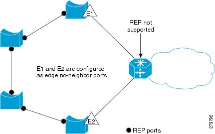
In access ring topologies, the neighboring switch might not support REP, as shown in Figure 4-2. In this case, you can configure the non-REP facing ports (E1 and E2) as edge no-neighbor ports. These ports inherit all the properties of edge ports. You can configure these no-neighbor ports as any other edge port and also enable the ports to send STP or REP topology change notices to the aggregation switch. In this case the STP Topology Change Notice (TCN) that is sent is a Multiple Spanning-Tree (MST) STP message.
These sections describes how to configure REP for the Cisco 7600 router:
•![]() Configuring REP over Ethernet Virtual Circuit
Configuring REP over Ethernet Virtual Circuit
•![]() Configuring Resilient Ethernet Protocol Configurable Timers
Configuring Resilient Ethernet Protocol Configurable Timers
Configuring REP over Ethernet Virtual Circuit
The REP over Ethernet Virtual Circuit (EVC) feature allows you to configure and manage ports on the interface, and not per service instance and can be used to block and unblock encapsulated vlans at service level.
An EVC port can have multiple service instances. Each service instance corresponds to a unique Event Flow Processor (EFP). By default, REP is disabled on all ports. REP can be configured only REP can selectively block or forward data traffic on particular VLANs. For EVC, the VLAN Id refers to the outer tag of the dot1q encapsulation that is configured on a service instance. REP is supported on a bridge-domain service. If ethernet vlan color-block all command is configured, REP is supported on connect and cross connect services.
Restrictions and Usage Guidelines
When configuring REP over EVC for the Cisco 7600 router, follow these guidelines and restrictions:
•![]() REP is not supported on service instances configured with encapsulation, untagged, or default type.
REP is not supported on service instances configured with encapsulation, untagged, or default type.
•![]() Cisco recommends that you begin by configuring one port and then configure the contiguous ports to minimize the number of segments and the number of blocked ports.
Cisco recommends that you begin by configuring one port and then configure the contiguous ports to minimize the number of segments and the number of blocked ports.
•![]() REP is not supported on mLACP.
REP is not supported on mLACP.
•![]() If more than two ports in a segment fail when no external neighbors are configured, one port goes into a forwarding state to maintain connectivity during configuration.
If more than two ports in a segment fail when no external neighbors are configured, one port goes into a forwarding state to maintain connectivity during configuration.
•![]() REP ports must be Layer 2 trunk ports or EVC ports.
REP ports must be Layer 2 trunk ports or EVC ports.
•![]() To avoid misconfiguration, you must configure all trunk ports in the segment with the same set of allowed VLANs.
To avoid misconfiguration, you must configure all trunk ports in the segment with the same set of allowed VLANs.
•![]() Since REP blocks all VLANs until another REP interface sends a message to unblock it, you might loose connectivity to the port. This happens if you enable REP in a Telnet session that accesses the EVC port through the same interface.
Since REP blocks all VLANs until another REP interface sends a message to unblock it, you might loose connectivity to the port. This happens if you enable REP in a Telnet session that accesses the EVC port through the same interface.
•![]() You cannot execute REP and STP/MST, or REP and Flex Links on the same segment or interface.
You cannot execute REP and STP/MST, or REP and Flex Links on the same segment or interface.
•![]() You cannot run REP and STP/MST, or REP and Flex Links on the same segment or interface.
You cannot run REP and STP/MST, or REP and Flex Links on the same segment or interface.
•![]() If you connect an STP network to the REP segment, ensure that the connection is at the segment edge. An STP connection that is not at the edge causes a bridging loop because STP does not run on REP segments. All STP BPDUs are dropped at REP interfaces.
If you connect an STP network to the REP segment, ensure that the connection is at the segment edge. An STP connection that is not at the edge causes a bridging loop because STP does not run on REP segments. All STP BPDUs are dropped at REP interfaces.
•![]() On a router if REP is enabled on two ports for a segment, both ports must either be a regular segment ports or edge ports. REP ports follow these rules on a router:
On a router if REP is enabled on two ports for a segment, both ports must either be a regular segment ports or edge ports. REP ports follow these rules on a router:
–![]() If only one port is configured in a segment, the port should be an edge port.
If only one port is configured in a segment, the port should be an edge port.
–![]() If two ports belong to the same segment, both ports must be edge ports or the regular segment ports.
If two ports belong to the same segment, both ports must be edge ports or the regular segment ports.
–![]() If two ports belong to the same segment and one is configured as an edge port and other as a regular segment port, the edge port is treated as a regular segment port.
If two ports belong to the same segment and one is configured as an edge port and other as a regular segment port, the edge port is treated as a regular segment port.
–![]() There can be only two edge ports in a segment, if there are two edge routers in a segment, each router can have only one edge port. All the other ports on the edge router function as normal ports.
There can be only two edge ports in a segment, if there are two edge routers in a segment, each router can have only one edge port. All the other ports on the edge router function as normal ports.
•![]() REP interfaces come up in a blocked state and remains in a blocked state until notified that it is safe to unblock.
REP interfaces come up in a blocked state and remains in a blocked state until notified that it is safe to unblock.
•![]() REP relays all LSL PDUs in untagged frames on the native VLAN andonly HFL packets are relayed on the admin vlan. However, BPA messages are untagged as well.
REP relays all LSL PDUs in untagged frames on the native VLAN andonly HFL packets are relayed on the admin vlan. However, BPA messages are untagged as well.
•![]() REP ports cannot be configured as:
REP ports cannot be configured as:
–![]() SPAN destination port
SPAN destination port
–![]() Private VLAN port
Private VLAN port
–![]() Tunnel port
Tunnel port
–![]() Access port
Access port
•![]() REP is supported on EtherChannels, but not on an individual port that belongs to an EtherChannel. It is supported on Swichports and EVC port-channels. REP is implemented on port-channels instead of its individual member links.
REP is supported on EtherChannels, but not on an individual port that belongs to an EtherChannel. It is supported on Swichports and EVC port-channels. REP is implemented on port-channels instead of its individual member links.
•![]() In case of double VLAN tagged frame, REP is implemented only on the outer VLAN tag.
In case of double VLAN tagged frame, REP is implemented only on the outer VLAN tag.
•![]() When an edge no-neighbor is configured on a router, configuring and unconfiguring an edge port is not allowed.
When an edge no-neighbor is configured on a router, configuring and unconfiguring an edge port is not allowed.
Configuring REP over EVC for the Cisco 7600 Router
This section describes how to configure REP over EVC for the Cisco 7600 router:
•![]() Configuring REP over EVC using Cross connect for the Cisco 7600 Router
Configuring REP over EVC using Cross connect for the Cisco 7600 Router
•![]() Configuring REP over EVC using connect for the Cisco 7600 Router
Configuring REP over EVC using connect for the Cisco 7600 Router
•![]() Configuring REP over EVC using bridge domain for the Cisco 7600 Router
Configuring REP over EVC using bridge domain for the Cisco 7600 Router
Configuring REP over EVC using Cross connect for the Cisco 7600 Router
This section describes how to configure REP over EVC using cross connect at the global configuration level.
SUMMARY STEPS
1. ![]() enable
enable
2. ![]() configure terminal
configure terminal
3. ![]() interface gigabitEthernet slot/subslot/port
interface gigabitEthernet slot/subslot/port
4. ![]() ether vlan color-block all
ether vlan color-block all
5. ![]() service instance id {ethernet [service-name}
service instance id {ethernet [service-name}
6. ![]() encapsulation dot1q vlan_id
encapsulation dot1q vlan_id
7. ![]() rewrite ingress tag
rewrite ingress tag
8. ![]() xconnect loopback_ip vc_id encapsulation mpls
xconnect loopback_ip vc_id encapsulation mpls
9. ![]() rep segment segment_id [edge [no-neighbor][primary]] [preferred]
rep segment segment_id [edge [no-neighbor][primary]] [preferred]
10. ![]() exit
exit
DETAILED STEPS
Examples
This example shows how to configure REP over EVC using cross connect.
Router# enable
Router# configure terminal
Router(config)# interface GigabitEthernet 5/3
Router(config-if-srv)# rep segment 3 edge
Router(config-if)# service instance 10 ethernet
Router(config-srv)# encapsulation dot1q 20
Router(config-if-srv)# rewrite ingress tag pop 2 sym
Router(config-if-srv)# xconnect 10.0.0.2 999 encapsulation MPLS
Router(config-if-srv)# exit
Configuring REP over EVC using connect for the Cisco 7600 Router
This section describes how to configure REP over EVC using connect at global configuration level.
SUMMARY STEPS
1. ![]() enable
enable
2. ![]() configure terminal
configure terminal
3. ![]() interface type slot/subslot/port
interface type slot/subslot/port
4. ![]() ether vlan color-block all
ether vlan color-block all
5. ![]() service instance id {Ethernet [service-name}
service instance id {Ethernet [service-name}
6. ![]() encapsulation dot1q vlan_id
encapsulation dot1q vlan_id
7. ![]() rewrite ingress tag {push {dot1q vlan-id | dot1q vlan-id second-dot1q vlan-id | dot1ad vlan-id dot1q vlan-id} | pop {1 | 2} | translate {1-to-1 {dot1q vlan-id | dot1ad vlan-id}| 2-to-1 dot1q vlan-id | dot1ad vlan-id}| 1-to-2 {dot1q vlan-id second-dot1q vlan-id | dot1ad vlan-id dot1q vlan-id} | 2-to-2 {dot1q vlan-id second-dot1q vlan-id | dot1ad vlan-id dot1q vlan-id}} [symmetric]
rewrite ingress tag {push {dot1q vlan-id | dot1q vlan-id second-dot1q vlan-id | dot1ad vlan-id dot1q vlan-id} | pop {1 | 2} | translate {1-to-1 {dot1q vlan-id | dot1ad vlan-id}| 2-to-1 dot1q vlan-id | dot1ad vlan-id}| 1-to-2 {dot1q vlan-id second-dot1q vlan-id | dot1ad vlan-id dot1q vlan-id} | 2-to-2 {dot1q vlan-id second-dot1q vlan-id | dot1ad vlan-id dot1q vlan-id}} [symmetric]
8. ![]() exit
exit
9. ![]() rep segment segment_id [edge [no-neighbor] [primary]] [preferred]
rep segment segment_id [edge [no-neighbor] [primary]] [preferred]
10. ![]() exit
exit
11. ![]() interface type slot/subslot/port
interface type slot/subslot/port
12. ![]() ether vlan color-block all
ether vlan color-block all
13. ![]() service instance id {Ethernet [service-name}
service instance id {Ethernet [service-name}
14. ![]() encapsulation dot1q vlan_id
encapsulation dot1q vlan_id
15. ![]() rewrite ingress tag {push {dot1q vlan-id | dot1q vlan-id second-dot1q vlan-id | dot1ad vlan-id dot1q vlan-id} | pop {1 | 2} | translate {1-to-1 {dot1q vlan-id | dot1ad vlan-id}| 2-to-1 dot1q vlan-id | dot1ad vlan-id}| 1-to-2 {dot1q vlan-id second-dot1q vlan-id | dot1ad vlan-id dot1q vlan-id} | 2-to-2 {dot1q vlan-id second-dot1q vlan-id | dot1ad vlan-id dot1q vlan-id}} [symmetric]
rewrite ingress tag {push {dot1q vlan-id | dot1q vlan-id second-dot1q vlan-id | dot1ad vlan-id dot1q vlan-id} | pop {1 | 2} | translate {1-to-1 {dot1q vlan-id | dot1ad vlan-id}| 2-to-1 dot1q vlan-id | dot1ad vlan-id}| 1-to-2 {dot1q vlan-id second-dot1q vlan-id | dot1ad vlan-id dot1q vlan-id} | 2-to-2 {dot1q vlan-id second-dot1q vlan-id | dot1ad vlan-id dot1q vlan-id}} [symmetric]
16. ![]() exit
exit
17. ![]() rep segment segment_id [edge [no-neighbor] [primary]] [preferred]
rep segment segment_id [edge [no-neighbor] [primary]] [preferred]
18. ![]() exit
exit
19. ![]() connect <connect_name> <interface> <service_instance_id> <interface> <service_instance_id>
connect <connect_name> <interface> <service_instance_id> <interface> <service_instance_id>
DETAILED STEPS
Examples
This example shows how to configure REP over EVC using connect.
Router# enable
Router# configure terminal
Router(config)# interface gigabitEthernet 3/0/0
Router(config-if)# ether vlan color-block all
Router(config-if)# service instance 10 ethernet
Router(config-if-srv)# encapsulation dot1q 10
Router(config-if-srv)# rewrite ingress tag pop 1 symmetric
Router(config-if-srv)# exit
Router(config-if)# rep segment 2 edge primary
Router(config-if)# exit
Router(config)# interface gigabitEthernet 4/0/0
Router(config-if)# service instance 20 ethernet
Router(config-if-srv)# encapsulation dot1q 20
Router(config-if-srv)# rewrite ingress tag pop 1 symmetric
Router(config-if-srv)# exit
Router(config-if)# rep segment 2 edge
Router(config-if)# exit
Router(config)#connect test gigabitEthernet 3/0/0 10 gigabitEthernet 4/0/0 20
Router(config-connection)#end
Configuring REP over EVC using bridge domain for the Cisco 7600 Router
This section describes how to configure REP over EVC using bridge domain at service instance level.
SUMMARY STEPS
1. ![]() enable
enable
2. ![]() configure terminal
configure terminal
3. ![]() interface type slot/subslot/port
interface type slot/subslot/port
4. ![]() service instance id {Ethernet [service-name}
service instance id {Ethernet [service-name}
5. ![]() encapsulation dot1q vlan_id
encapsulation dot1q vlan_id
6. ![]() rewrite ingress tag {push {dot1q vlan-id | dot1q vlan-id second-dot1q vlan-id | dot1ad vlan-id dot1q vlan-id} | pop {1 | 2} | translate {1-to-1 {dot1q vlan-id | dot1ad vlan-id}| 2-to-1 dot1q vlan-id | dot1ad vlan-id}| 1-to-2 {dot1q vlan-id second-dot1q vlan-id | dot1ad vlan-id dot1q vlan-id} | 2-to-2 {dot1q vlan-id second-dot1q vlan-id | dot1ad vlan-id dot1q vlan-id}} {symmetric}
rewrite ingress tag {push {dot1q vlan-id | dot1q vlan-id second-dot1q vlan-id | dot1ad vlan-id dot1q vlan-id} | pop {1 | 2} | translate {1-to-1 {dot1q vlan-id | dot1ad vlan-id}| 2-to-1 dot1q vlan-id | dot1ad vlan-id}| 1-to-2 {dot1q vlan-id second-dot1q vlan-id | dot1ad vlan-id dot1q vlan-id} | 2-to-2 {dot1q vlan-id second-dot1q vlan-id | dot1ad vlan-id dot1q vlan-id}} {symmetric}
7. ![]() bridge-domain bd_Id
bridge-domain bd_Id
8. ![]() exit
exit
9. ![]() rep segment segment_id [edge [no-neighbor] [primary]] [preferred]
rep segment segment_id [edge [no-neighbor] [primary]] [preferred]
10. ![]() exit
exit
DETAILED STEPS
Examples
This example shows how to configure REP over EVC using bridge domain.
Router# enable
Router# configure terminal
Router(config)# interface gigabitEthernet 3/0/0
Router(config-if)# service instance 10 ethernet
Router(config-if-srv)# encapsulation dot1q 10
Router(config-if-srv)# rewrite ingress tag pop 1 symmetric
Router(config-if-srv)# bridge-domain 100
Router(config-if-srv)# exit
Router(config-if)# rep segment 2 edge
Router(config-if)# end
This example shows how to configure REP with the edge no-neighbor keyword.
Router# enable
Router# configure terminal
Router(config)# interface gigabitEthernet 7/1
Router(config-if)# switchport
Router(config-if)# switchport mode trunk
Router(config-if)# rep segment 1 edge no-neighbor primary
Router(config-if)# end
Verification
You can use the show rep topology, show rep topology detail and show interface rep commands to verify the REP over EVC configuration. This information is displayed as sample output:
•![]() Specific EVCs if an EVC ID is specified.
Specific EVCs if an EVC ID is specified.
•![]() All the EVCs on an interface if an interface is specified.
All the EVCs on an interface if an interface is specified.
•![]() The detailed option provides additional information about the EVC. This can be given on RP and LC consoles to determine custom ethertype configured under a physical port.
The detailed option provides additional information about the EVC. This can be given on RP and LC consoles to determine custom ethertype configured under a physical port.
Example of show rep topology command:
Router#show rep topology
REP Segment 3
BridgeName PortName Edge Role
---------------- ---------- ---- ----
Router Gi4/0/0 Pri Open
REP-ALPHA Gi2/12 Open
REP-ALPHA Fa3/1 Open
REP-BETA Fa1/1 Open
REP-BETA Gi6/1 Open
Router Gi3/4 Sec Alt
--
Example of show rep topology detail command.
Router#show rep topology segment 3 detail
REP Segment 3
Router, Gi4/0/0 (Primary Edge)
Open Port, all vlans forwarding
Bridge MAC: 0015.fa66.ff80
Port Number: 0301
Port Priority: 000
Neighbor Number: 1 / [-6]
REP-ALPHA, Gi2/12 (Intermediate)
Open Port, all vlans forwarding
Bridge MAC: 0005.7495.cd00
Port Number: 010C
Port Priority: 000
Neighbor Number: 2 / [-5]
REP-ALPHA, Fa3/1 (Intermediate)
Open Port, all vlans forwarding
Bridge MAC: 0005.7495.cd00
Port Number: 0201
Port Priority: 000
Neighbor Number: 3 / [-4]
REP-BETA, Fa1/1 (Intermediate)
Open Port, all vlans forwarding
Bridge MAC: 0005.7495.c900
Port Number: 001
Port Priority: 000
Neighbor Number: 4 / [-3]
REP-BETA, Gi6/1 (Intermediate)
Open Port, all vlans forwarding
Bridge MAC: 0005.7495.c900
Port Number: 0501
Port Priority: 000
Neighbor Number: 5 / [-2]
Router, Gi3/4 (Secondary Edge)
Alternate Port, some vlans blocked
Bridge MAC: 0015.fa66.ff80
Port Number: 0204
Port Priority: 010
Neighbor Number: 6 / [-1]
Example of show interface <> rep command:
Router#show interface gig4/0/0 rep detail
GigabitEthernet4/0/0 REP enabled
Segment-id: 3 (Primary Edge)
PortID: 03010015FA66FF80
Preferred flag: No
Operational Link Status: TWO_WAY
Current Key: 02040015FA66FF804050
Port Role: Open
Blocked VLAN: <empty>
Admin-vlan: 1
Preempt Delay Timer: disabled
Configured Load-balancing Block Port: none
Configured Load-balancing Block VLAN: none
STCN Propagate to: none
LSL PDU rx: 999, tx: 652
HFL PDU rx: 0, tx: 0
BPA TLV rx: 500, tx: 4
BPA (STCN, LSL) TLV rx: 0, tx: 0
BPA (STCN, HFL) TLV rx: 0, tx: 0
EPA-ELECTION TLV rx: 6, tx: 5
EPA-COMMAND TLV rx: 0, tx: 0
EPA-INFO TLV rx: 135, tx: 136
Show outputs for REP with Edge No-Neighbor keyword
Example of show rep topology command with REP edge no-neighbor keyword:
Router#show rep topology
REP Segment 3
BridgeName PortName Edge Role
---------------- ---------- ---- ----
sw8-ts8-51 Gi0/2 Pri* Open
sw9-ts11-50 Gi1/0/4 Open
sw9-ts11-50 Gi1/0/2 Open
sw1-ts11-45 Gi0/2 Alt
sw1-ts11-45 Po1 Open
sw8-ts8-51 Gi0/1 Sec* Open
--
Example of show rep topology detail command with REP edge no-neighbor keyword:
Router#show rep topology segment 3 detail
REP Segment 3
Router, Gi4/0/0 (Primary Edge No-Neighbor)
Open Port, all vlans forwarding
Bridge MAC: 0015.fa66.ff80
Port Number: 0301
Port Priority: 000
Neighbor Number: 1 / [-6]
REP-ALPHA, Gi2/12 (Intermediate)
Open Port, all vlans forwarding
Bridge MAC: 0005.7495.cd00
Port Number: 010C
Port Priority: 000
Neighbor Number: 2 / [-5]
REP-ALPHA, Fa3/1 (Intermediate)
Open Port, all vlans forwarding
Bridge MAC: 0005.7495.cd00
Port Number: 0201
Port Priority: 000
Neighbor Number: 3 / [-4]
REP-BETA, Fa1/1 (Intermediate)
Open Port, all vlans forwarding
Bridge MAC: 0005.7495.c900
Port Number: 001
Port Priority: 000
Neighbor Number: 4 / [-3]
REP-BETA, Gi6/1 (Intermediate)
Open Port, all vlans forwarding
Bridge MAC: 0005.7495.c900
Port Number: 0501
Port Priority: 000
Neighbor Number: 5 / [-2]
Router, Gi3/4 (Secondary Edge)
Alternate Port, some vlans blocked
Bridge MAC: 0015.fa66.ff80
Port Number: 0204
Port Priority: 010
Neighbor Number: 6 / [-1]
Example of show interface <> rep command with REP edge no-neighbor keyword:
Router#show interface gig4/0/0 rep detail
GigabitEthernet4/0/0 REP enabled
Segment-id: 3 (Primary Edge No-Neighbor)
PortID: 03010015FA66FF80
Preferred flag: No
Operational Link Status: TWO_WAY
Current Key: 02040015FA66FF804050
Port Role: Open
Blocked VLAN: <empty>
Admin-vlan: 1
Preempt Delay Timer: disabled
Configured Load-balancing Block Port: none
Configured Load-balancing Block VLAN: none
STCN Propagate to: none
LSL PDU rx: 999, tx: 652
HFL PDU rx: 0, tx: 0
BPA TLV rx: 500, tx: 4
BPA (STCN, LSL) TLV rx: 0, tx: 0
BPA (STCN, HFL) TLV rx: 0, tx: 0
EPA-ELECTION TLV rx: 6, tx: 5
EPA-COMMAND TLV rx: 0, tx: 0
EPA-INFO TLV rx: 135, tx: 136
Configuring Resilient Ethernet Protocol Configurable Timers
The REP Configurable Timer (REP Fast Hellos) feature provides a fast re-convergence in a ring topology with higher timer granularity and quicker failure detection on the remote side. The feature also supports improved convergence of REP segments having nodes with copper based SFP's, where the link detection time varies between 300ms to 700 ms.
With the REP Link Status Layer (LSL) ageout timer configuration, the failure detection time can be configured between a range of 120 millisecond to 10,000 millisecond, in multiples of 40ms. The result of this configuration is that, even if the copper pull takes about 700 ms to notify the remote end about the failure, the REP Configurable Timers process will detect it much earlier and takes subsequent action for the failure recovery with in 200 ms.
Restrictions and Usage Guidelines
Follow these guidelines and restrictions:
•![]() The LSL Age Out Timer configuration is available on switchports, EVC, L2 Port-channel and Port-channel EVC interfaces.
The LSL Age Out Timer configuration is available on switchports, EVC, L2 Port-channel and Port-channel EVC interfaces.
•![]() The SUP 720, RSP 720, RSP 10G supervisors and the ES20, ES40, and LAN line cards support the REP Configurable Timers configuration.
The SUP 720, RSP 720, RSP 10G supervisors and the ES20, ES40, and LAN line cards support the REP Configurable Timers configuration.
•![]() While configuring REP configurable timers, we recommend you shut the port, configure REP and only then use the no shut command. This prevents the REP from flapping and generating large number of internal messages.
While configuring REP configurable timers, we recommend you shut the port, configure REP and only then use the no shut command. This prevents the REP from flapping and generating large number of internal messages.
•![]() If incompatible switches are neighbors, configure the correct LSL Age Out value first. In some scenarios, you might not get the expected convergence range.
If incompatible switches are neighbors, configure the correct LSL Age Out value first. In some scenarios, you might not get the expected convergence range.
•![]() In order to inter-operate with switches running old IOS versions, the default LSL Age Out time is set to 5 seconds, default LSL retries is 5, and the hello packet is sent every one second.
In order to inter-operate with switches running old IOS versions, the default LSL Age Out time is set to 5 seconds, default LSL retries is 5, and the hello packet is sent every one second.
•![]() Except for the LSL Age Out time, all the other timer values are retained. For example, the EPA (End Port Advertisement) hello timer continues to be 4 seconds, as it is not required to send EPA PDUs at a higher frequency.
Except for the LSL Age Out time, all the other timer values are retained. For example, the EPA (End Port Advertisement) hello timer continues to be 4 seconds, as it is not required to send EPA PDUs at a higher frequency.
•![]() While configuring REP configurable timers, we recommend you configure the REP LSL number of retries first and then configure the REP LSL age out timer value.
While configuring REP configurable timers, we recommend you configure the REP LSL number of retries first and then configure the REP LSL age out timer value.
•![]() Effective from Cisco IOS release 15.1(2)S:
Effective from Cisco IOS release 15.1(2)S:
–![]() The REP Configurable Timers feature is SSO compliant for RSP720, RSP10G (endor) and SUP720 supervisors.
The REP Configurable Timers feature is SSO compliant for RSP720, RSP10G (endor) and SUP720 supervisors.
–![]() The REP Configurable Timers feature on SSO is not supported with SUP32 supervisor.
The REP Configurable Timers feature on SSO is not supported with SUP32 supervisor.
–![]() The REP LSL Age Out value can be configured as low as 1520 ms (approximately 500 ms * 3) for HA systems as this prevents traffic loss.
The REP LSL Age Out value can be configured as low as 1520 ms (approximately 500 ms * 3) for HA systems as this prevents traffic loss.
•![]() The REP Configurable Timers feature is supported only on Cisco 7600 S-chassis.
The REP Configurable Timers feature is supported only on Cisco 7600 S-chassis.
Configuring REP Configurable Timers for the Cisco 7600 Router
This section describes how to configure the LSL age out timer and the LSL number of retries on a Cisco 7600 router:
•![]() Configuring the REP Link Status Layer Retries
Configuring the REP Link Status Layer Retries
•![]() Configuring the REP Link Status Layer Age Out Timer
Configuring the REP Link Status Layer Age Out Timer
Configuring the REP Link Status Layer Retries
This section describes how to configure REP link status layer number of retries at interface configuration level.
SUMMARY STEPS
1. ![]() enable
enable
2. ![]() configure terminal
configure terminal
3. ![]() interface type slot/subslot/port
interface type slot/subslot/port
4. ![]() rep segment segment_id [edge [no-neighbor] [primary]] [preferred]
rep segment segment_id [edge [no-neighbor] [primary]] [preferred]
5. ![]() rep lsl-retries <no-of-retries>
rep lsl-retries <no-of-retries>
6. ![]() end
end
DETAILED STEPS
Examples
This example shows how to configure REP link status layer number of retries.
Router# enable
Router# configure terminal
Router(config)# interface gigabitethernet 2/0/3
Router(config-if)# rep segment 2 edge primary
Router(config-if)# rep lsl-retries 4
Router(config-if)# end
Configuring the REP Link Status Layer Age Out Timer
This section describes how to configure the REP Link Status Layer Age Out Timer at interface configuration level.
SUMMARY STEPS
1. ![]() enable
enable
2. ![]() configure terminal
configure terminal
3. ![]() interface type slot/subslot/port
interface type slot/subslot/port
4. ![]() rep segment segment_id [edge [no-neighbor] [primary]] [preferred]
rep segment segment_id [edge [no-neighbor] [primary]] [preferred]
5. ![]() rep lsl-age-timer <lsl-age-timer>
rep lsl-age-timer <lsl-age-timer>
6. ![]() end
end
DETAILED STEPS
Examples
This example shows how to configure REP link status layer number of retries.
Router# enable
Router# configure terminal
Router(config)# interface gigabitethernet 2/0/3
Router(config-if)# rep segment 2 edge primary
Router(config-if)# rep lsl-retries 4
Router(config-if)# end
Configuring the REP Link Status Layer Age Out Timer
This section describes how to configure the REP Link Status Layer Age Out Timer at interface configuration level.
SUMMARY STEPS
1. ![]() enable
enable
2. ![]() configure terminal
configure terminal
3. ![]() interface type slot/subslot/port
interface type slot/subslot/port
4. ![]() rep segment segment_id [edge [primary]] [preferred]
rep segment segment_id [edge [primary]] [preferred]
5. ![]() rep lsl-age-timer <lsl-age-timer>
rep lsl-age-timer <lsl-age-timer>
6. ![]() end
end
DETAILED STEPS
Examples
This example shows how to configure REP link status layer ageout timer value.
Router# enable
Router# configure terminal
Router(config)# interface GigabitEthernet 5/0/2
Router(config-if)# rep segment 1 edge primary
Router(config-if)# rep lsl-age-timer 2000
Router(config-if)# end
Verification
Use the show interfaces <interface name> rep detail command to view the configured LSL number of retries and the LSL Age Out timer values.
7600-1#show interfaces GigabitEthernet11/0/1 rep detail
GigabitEthernet11/0/1 REP enabled
Segment-id: 10 (Segment)
PortID: 0A010009B6D8F700
Preferred flag: No
Operational Link Status: NO_NEIGHBOR
Current Key: 0A010009B6D8F700EEA1
Port Role: Fail No Ext Neighbor
Blocked VLAN: 1-4094
Admin-vlan: 1
Preempt Delay Timer: disabled
LSL Ageout Timer: 120 ms
LSL Ageout Retries: 3
Configured Load-balancing Block Port: none
Configured Load-balancing Block VLAN: none
STCN Propagate to: none
LSL PDU rx: 0, tx: 175
HFL PDU rx: 0, tx: 0
BPA TLV rx: 0, tx: 0
BPA (STCN, LSL) TLV rx: 0, tx: 0
BPA (STCN, HFL) TLV rx: 0, tx: 0
EPA-ELECTION TLV rx: 0, tx: 0
EPA-COMMAND TLV rx: 0, tx: 0
EPA-INFO TLV rx: 0, tx: 0
Troubleshooting
Table 2-20 provides troubleshooting solutions for the REP feature.
Table 2-20 Troubleshooting Reverse REP feature
Configuring CFM over EFP Interface with cross connect
Ethernet Connectivity Fault Management (CFM) is an end-to-end per-service-instance Ethernet layer OAM protocol that includes proactive connectivity monitoring, fault verification, and fault isolation. Currently, Ethernet CFM supports Up facing and Down facing Maintenance Endpoints (MEPs). For information on Ethernet Connectivity Fault Management, see http://www.cisco.com/en/US/docs/ios/12_2sr/12_2sra/feature/guide/srethcfm.html
The CFM over EFP Interface with xconnect feature allows you to:
•![]() Forward continuity check messages (CCM) towards the core over cross connect pseudowires.
Forward continuity check messages (CCM) towards the core over cross connect pseudowires.
•![]() Receive CFM messages from the core.
Receive CFM messages from the core.
•![]() Forward CFM messages to the access side (after Continuity Check Database [CCDB] based on maintenance point [MP] filtering rules).
Forward CFM messages to the access side (after Continuity Check Database [CCDB] based on maintenance point [MP] filtering rules).
Restrictions and Usage Guidelines
When configuring CFM over EFP Interface with cross connect, follow these restrictions and usage guidelines:
•![]() The following line cards are supported:
The following line cards are supported:
–![]() ES20 line cards
ES20 line cards
–![]() ES+ line cards
ES+ line cards
•![]() Only a single down-facing MEP is allowed on the L2VFI.
Only a single down-facing MEP is allowed on the L2VFI.
•![]() As the number of PEs in a VPLS instance scale up, the number of CFM CC messages processed increases. Accordingly, the configuration of the down-facing MEP on L2VFI for large fully meshed PW topologies should be considered for only premium valued networks.
As the number of PEs in a VPLS instance scale up, the number of CFM CC messages processed increases. Accordingly, the configuration of the down-facing MEP on L2VFI for large fully meshed PW topologies should be considered for only premium valued networks.
•![]() In the design of CFM domains, the maintenance level of an Down-facing MEP on the L2VFI interface must be lower than the level from the AC.
In the design of CFM domains, the maintenance level of an Down-facing MEP on the L2VFI interface must be lower than the level from the AC.
•![]() Up MEP, Down MEP, and MIPs are supported.
Up MEP, Down MEP, and MIPs are supported.
Configuring CFM over EFP with xconnect for the Cisco 7600 Router
This section describes how to configure REP over EVC for the Cisco 7600 router:
•![]() Configuring CFM over EFP Interface with Cross Connect—Basic Configuration
Configuring CFM over EFP Interface with Cross Connect—Basic Configuration
•![]() Configuring CFM over EFP Interface with Cross Connect—Single Tag VLAN Cross Connect
Configuring CFM over EFP Interface with Cross Connect—Single Tag VLAN Cross Connect
•![]() Configuring CFM over EFP Interface with Cross Connect—Double Tag VLAN Cross Connect
Configuring CFM over EFP Interface with Cross Connect—Double Tag VLAN Cross Connect
•![]() Configuring CFM over EFP Interface with Cross Connect—Selective QinQ Cross Connect
Configuring CFM over EFP Interface with Cross Connect—Selective QinQ Cross Connect
•![]() Configuring CFM over EFP Interface with Cross Connect—Port-Based Cross Connect Tunnel
Configuring CFM over EFP Interface with Cross Connect—Port-Based Cross Connect Tunnel
•![]() Configuring CFM over EFP Interface with Cross Connect—Port Channel-Based Cross Connect Tunnel
Configuring CFM over EFP Interface with Cross Connect—Port Channel-Based Cross Connect Tunnel
Configuring CFM over EFP Interface with Cross Connect—Basic Configuration
This section describes how to configure CFM over EFP Interface with cross connect.
SUMMARY STEPS
1. ![]() enable
enable
2. ![]() configure terminal
configure terminal
3. ![]() pseudowire-class [pw-class-name]
pseudowire-class [pw-class-name]
4. ![]() encapsulation mpls
encapsulation mpls
5. ![]() exit
exit
6. ![]() interface gigabitethernet slot/port or interface tengigabitethernet slot/port
interface gigabitethernet slot/port or interface tengigabitethernet slot/port
7. ![]() service instance id {Ethernet [service-name}
service instance id {Ethernet [service-name}
8. ![]() encapsulation untagged, dot1q vlan_id
encapsulation untagged, dot1q vlan_id
9. ![]() xconnect peer-ip-address vc-id {encapsulation {l2tpv3 [manual] | mpls [manual]} | pw-class pw-class-name }[pw-class pw-class-name] [sequencing {transmit | receive | both}]
xconnect peer-ip-address vc-id
{encapsulation {l2tpv3 [manual] | mpls
[manual]} | pw-class pw-class-name
}[pw-class pw-class-name] [sequencing
{transmit | receive | both}]
10. ![]() cfm mep domain domain-name [up | down] mpid mpid-value [cos cos-value]
cfm mep domain domain-name [up | down] mpid mpid-value [cos cos-value]
11. ![]() exit
exit
DETAILED STEPS
Examples
This example shows how to configure CFM over EVC using cross connect.
PE3#conf terminal
Enter configuration commands, one per line. End with CNTL/Z.
PE3(config)#ethernet cfm domain L6 level 6
PE3(config-ecfm)# service s256 evc 256
PE3(config-ecfm-srv)# continuity-check
PE3(config-ecfm-srv)#end
PE3(config)#int ten 2/0/0
PE3(config-if)#no ip address
PE3(config-if)# service instance 256 ethernet 256
PE3(config-if-srv)# encapsulation dot1q 256
PE3(config-if-srv)# xconnect 1.1.1.1 1 encapsulation mpls
PE3(cfg-if-ether-vc-xconn)# cfm mep domain L6 mpid 256
PE3(config-if-srv-ecfm-mep)#end
PE3#
PE3(config)#ethernet cfm domain L2 level 2
PE3(config-ecfm)# service s256 evc 256 direction down
PE3(config-ecfm-srv)# continuity-check
PE3(config-ecfm-srv)#end
PE3#
PE3(config)#int ten 2/0/0
PE3(config-if)#no ip address
PE3(config-if)# service instance 256 ethernet 256
PE3(config-if-srv)# encapsulation dot1q 256
PE3(config-if-srv)# xconnect 1.1.1.1 1 encapsulation mpls
PE3(cfg-if-ether-vc-xconn)# cfm mep domain L6 mpid 256
PE3(config-if-srv-ecfm-mep)#end
PE3#
Configuring CFM over EFP Interface with Cross Connect—Single Tag VLAN Cross Connect
This section describes how to configure CFM over EFP Interface with Single Tag VLAN cross connect.
SUMMARY STEPS
1. ![]() enable
enable
2. ![]() configure terminal
configure terminal
3. ![]() interface type slot/subslot/port or interface tengigabitethernet slot/port
interface type slot/subslot/port or interface tengigabitethernet slot/port
4. ![]() service instance id {Ethernet [service-name}
service instance id {Ethernet [service-name}
5. ![]() encapsulation untagged dot1q {any | vlan-id[vlan-id[vlan-id]} second-dot1q {any |vlan-id[vlan-id[vlan-id]]}
encapsulation untagged dot1q {any | vlan-id[vlan-id[vlan-id]} second-dot1q {any |vlan-id[vlan-id[vlan-id]]}
6. ![]() rewrite ingress tag {push {dot1q vlan-id | dot1q vlan-id second-dot1q vlan-id | dot1ad vlan-id dot1q vlan-id} | pop {1 | 2} | translate {1-to-1 {dot1q vlan-id | dot1ad vlan-id}| 2-to-1 dot1q vlan-id | dot1ad vlan-id}| 1-to-2 {dot1q vlan-id second-dot1q vlan-id | dot1ad vlan-id dot1q vlan-id} | 2-to-2 {dot1q vlan-id second-dot1q vlan-id | dot1ad vlan-id dot1q vlan-id}} [symmetric]
rewrite ingress tag {push {dot1q vlan-id | dot1q vlan-id second-dot1q vlan-id | dot1ad vlan-id dot1q vlan-id} | pop {1 | 2} | translate {1-to-1 {dot1q vlan-id | dot1ad vlan-id}| 2-to-1 dot1q vlan-id | dot1ad vlan-id}| 1-to-2 {dot1q vlan-id second-dot1q vlan-id | dot1ad vlan-id dot1q vlan-id} | 2-to-2 {dot1q vlan-id second-dot1q vlan-id | dot1ad vlan-id dot1q vlan-id}} [symmetric]
7. ![]() xconnect peer-ip-address vc-id {encapsulation {l2tpv3 [manual] | mpls [manual]} | pw-class pw-class-name }[pw-class pw-class-name] [sequencing {transmit | receive | both}]
xconnect peer-ip-address vc-id {encapsulation {l2tpv3 [manual] | mpls [manual]} | pw-class pw-class-name }[pw-class pw-class-name] [sequencing {transmit | receive | both}]
8. ![]() cfm mep domain domain-name [up | down] mpid mpid-value [cos cos-value]
cfm mep domain domain-name [up | down] mpid mpid-value [cos cos-value]
DETAILED STEPS
Examples
This example shows how to configure CFM over EFP Interface with Single Tag VLAN cross connect:
PE3(config)#ethernet cfm domain L2 level 2
PE3(config-ecfm)# service s256 evc 256 direction down
PE3(config-ecfm-srv)# continuity-check
PE3(config-ecfm-srv)#end
PE3#
PE3(config)#int ten 2/0/0
PE3(config-if)#no ip address
PE3(config-if)# service instance 256 ethernet 256
PE3(config-if-srv)# encapsulation dot1q 256
PE3(config-if-srv)# xconnect 1.1.1.1 1 encapsulation mpls
PE3(cfg-if-ether-vc-xconn)# cfm mep domain L6 mpid 256
PE3(config-if-srv-ecfm-mep)#end
PE3#
Configuring CFM over EFP Interface with Cross Connect—Double Tag VLAN Cross Connect
This section describes how to configure CFM over EFP Interface with Double Tag VLAN cross connect.
SUMMARY STEPS
1. ![]() enable
enable
2. ![]() configure terminal
configure terminal
3. ![]() interface type slot/subslot/port
interface type slot/subslot/port
4. ![]() service instance id {Ethernet [service-name}
service instance id {Ethernet [service-name}
5. ![]() encapsulation untagged dot1q {any | vlan-id[vlan-id[vlan-id]} second-dot1q {any |vlan-id[vlan-id[vlan-id]]}
encapsulation untagged dot1q {any | vlan-id[vlan-id[vlan-id]} second-dot1q {any |vlan-id[vlan-id[vlan-id]]}
6. ![]() rewrite ingress tag {push {dot1q vlan-id | dot1q vlan-id second-dot1q vlan-id | dot1ad vlan-id dot1q vlan-id} | pop {1 | 2} | translate {1-to-1 {dot1q vlan-id | dot1ad vlan-id}| 2-to-1 dot1q vlan-id | dot1ad vlan-id}| 1-to-2 {dot1q vlan-id second-dot1q vlan-id | dot1ad vlan-id dot1q vlan-id} | 2-to-2 {dot1q vlan-id second-dot1q vlan-id | dot1ad vlan-id dot1q vlan-id}} [symmetric]
rewrite ingress tag {push {dot1q vlan-id | dot1q vlan-id second-dot1q vlan-id | dot1ad vlan-id dot1q vlan-id} | pop {1 | 2} | translate {1-to-1 {dot1q vlan-id | dot1ad vlan-id}| 2-to-1 dot1q vlan-id | dot1ad vlan-id}| 1-to-2 {dot1q vlan-id second-dot1q vlan-id | dot1ad vlan-id dot1q vlan-id} | 2-to-2 {dot1q vlan-id second-dot1q vlan-id | dot1ad vlan-id dot1q vlan-id}} [symmetric]
7. ![]() xconnect peer-ip-address vc-id {encapsulation {l2tpv3 [manual] | mpls [manual]} | pw-class pw-class-name }[pw-class pw-class-name] [sequencing {transmit | receive | both}]
xconnect peer-ip-address vc-id {encapsulation {l2tpv3 [manual] | mpls [manual]} | pw-class pw-class-name }[pw-class pw-class-name] [sequencing {transmit | receive | both}]
8. ![]() cfm mep domain domain-name [up | down] mpid mpid-value [cos cos-value]
cfm mep domain domain-name [up | down] mpid mpid-value [cos cos-value]
9. ![]() exit
exit
DETAILED STEPS
Examples
This example shows how to configure CFM over EFP Interface with Double Tag VLAN cross connect:
PE3(config)#ethernet cfm domain L2 level 2
PE3(config-ecfm)# service s256 evc 256 direction down
PE3(config-ecfm-srv)# continuity-check
PE3(config-ecfm-srv)#end
PE3#
PE3(config)#int ten 2/0/0
PE3(config-if)#no ip address
PE3(config-if)# service instance 256 ethernet 256
PE3(config-if-srv)# encapsulation dot1q 256 second-dot1q 257
PE3(config-if-srv)# xconnect 1.1.1.1 1 encapsulation mpls
PE3(cfg-if-ether-vc-xconn)# cfm mep domain L6 mpid 256
PE3(config-if-srv-ecfm-mep)#end
PE3#
Configuring CFM over EFP Interface with Cross Connect—Selective QinQ Cross Connect
This section describes how to configure CFM over EFP Interface with Selective QinQ cross connect.
SUMMARY STEPS
1. ![]() enable
enable
2. ![]() configure terminal
configure terminal
3. ![]() interface type slot/subslot/port
interface type slot/subslot/port
4. ![]() exit
exit
5. ![]() service instance id {Ethernet [service-name}
service instance id {Ethernet [service-name}
6. ![]() encapsulation untagged dot1q {any | vlan-id[vlan-id[vlan-id]} second-dot1q {any |vlan-id[vlan-id[vlan-id]]}
encapsulation untagged dot1q {any | vlan-id[vlan-id[vlan-id]} second-dot1q {any |vlan-id[vlan-id[vlan-id]]}
7. ![]() xconnect peer-ip-address vc-id {encapsulation {l2tpv3 [manual] | mpls [manual]} | pw-class pw-class-name }[pw-class pw-class-name] [sequencing {transmit | receive | both}]
xconnect peer-ip-address vc-id {encapsulation {l2tpv3 [manual] | mpls [manual]} | pw-class pw-class-name }[pw-class pw-class-name] [sequencing {transmit | receive | both}]
8. ![]() cfm mep domain domain-name [up | down] mpid mpid-value [cos cos-value]
cfm mep domain domain-name [up | down] mpid mpid-value [cos cos-value]
9. ![]() exit
exit
DETAILED STEPS
Examples
This example shows how to configure CFM over EFP Interface with Selective QinQ cross connect:
PE3(config)#ethernet cfm domain L2 level 2
PE3(config-ecfm)# service s256 evc 256 direction down
PE3(config-ecfm-srv)# continuity-check
PE3(config-ecfm-srv)#end
PE3#
PE3(config)#int ten 2/0/0
PE3(config-if)#no ip address
PE3(config-if)# service instance 256 ethernet 256
PE3(config-if-srv)# encapsulation dot1q 256 second-dot1q 257 cos 7
PE3(config-if-srv)# xconnect 1.1.1.1 1 encapsulation mpls
PE3(cfg-if-ether-vc-xconn)# cfm mep domain L6 mpid 256
PE3(config-if-srv-ecfm-mep)#end
PE3#
Configuring CFM over EFP Interface with Cross Connect—Port-Based Cross Connect Tunnel
This section describes how to configure CFM over EFP Interface with Port-Based cross connect Tunnel.
SUMMARY STEPS
1. ![]() enable
enable
2. ![]() configure terminal
configure terminal
3. ![]() interface type slot/subslot/port
interface type slot/subslot/port
4. ![]() service instance id {Ethernet [service-name}
service instance id {Ethernet [service-name}
5. ![]() encapsulation untagged dot1q {any | vlan-id[vlan-id[vlan-id]} second-dot1q {any |vlan-id[vlan-id[vlan-id]]}
encapsulation untagged dot1q {any | vlan-id[vlan-id[vlan-id]} second-dot1q {any |vlan-id[vlan-id[vlan-id]]}
6. ![]() xconnect peer-ip-address vc-id {encapsulation {l2tpv3 [manual] | mpls [manual]} | pw-class pw-class-name }[pw-class pw-class-name] [sequencing {transmit | receive | both}]
xconnect peer-ip-address vc-id {encapsulation {l2tpv3 [manual] | mpls [manual]} | pw-class pw-class-name }[pw-class pw-class-name] [sequencing {transmit | receive | both}]
7. ![]() cfm mep domain domain-name [up | down] mpid mpid-value [cos cos-value]
cfm mep domain domain-name [up | down] mpid mpid-value [cos cos-value]
8. ![]() exit
exit
DETAILED STEPS
Examples
This example shows how to configure CFM over EFP Interface with Port-Based cross connect Tunnel:
PE3(config)#ethernet cfm domain L2 level 2
PE3(config-ecfm)# service s256 evc 256 direction down
PE3(config-ecfm-srv)# continuity-check
PE3(config-ecfm-srv)#end
PE3#
PE3(config)#int ten 2/0/0
PE3(config-if)#no ip address
PE3(config-if)# service instance 256 ethernet 256
PE3(config-if-srv)# encapsulation dot1q 256
PE3(config-if-srv)# xconnect 1.1.1.1 1 encapsulation mpls
PE3(cfg-if-ether-vc-xconn)# cfm mep domain L6 mpid 256
PE3(config-if-srv-ecfm-mep)#end
PE3#
Configuring CFM over EFP Interface with Cross Connect—Port Channel-Based Cross Connect Tunnel
This section describes how to configure CFM over EFP Interface with Port Channel-Based cross connect Tunnel.
SUMMARY STEPS
1. ![]() enable
enable
2. ![]() configure terminal
configure terminal
3. ![]() interface type slot/subslot/port
interface type slot/subslot/port
4. ![]() service instance id {Ethernet [service-name}
service instance id {Ethernet [service-name}
5. ![]() encapsulation untagged dot1q {any | vlan-id[vlan-id[vlan-id]} second-dot1q {any |vlan-id[vlan-id[vlan-id]]}
encapsulation untagged dot1q {any | vlan-id[vlan-id[vlan-id]} second-dot1q {any |vlan-id[vlan-id[vlan-id]]}
6. ![]() rewrite ingress tag {push {dot1q vlan-id | dot1q vlan-id second-dot1q vlan-id | dot1ad vlan-id dot1q vlan-id} | pop {1 | 2} | translate {1-to-1 {dot1q vlan-id | dot1ad vlan-id}| 2-to-1 dot1q vlan-id | dot1ad vlan-id}| 1-to-2 {dot1q vlan-id second-dot1q vlan-id | dot1ad vlan-id dot1q vlan-id} | 2-to-2 {dot1q vlan-id second-dot1q vlan-id | dot1ad vlan-id dot1q vlan-id}} [symmetric]
rewrite ingress tag {push {dot1q vlan-id | dot1q vlan-id second-dot1q vlan-id | dot1ad vlan-id dot1q vlan-id} | pop {1 | 2} | translate {1-to-1 {dot1q vlan-id | dot1ad vlan-id}| 2-to-1 dot1q vlan-id | dot1ad vlan-id}| 1-to-2 {dot1q vlan-id second-dot1q vlan-id | dot1ad vlan-id dot1q vlan-id} | 2-to-2 {dot1q vlan-id second-dot1q vlan-id | dot1ad vlan-id dot1q vlan-id}} [symmetric]
7. ![]() xconnect peer-ip-address vc-id {encapsulation {l2tpv3 [manual] | mpls [manual]} | pw-class pw-class-name }[pw-class pw-class-name] [sequencing {transmit | receive | both}]
xconnect peer-ip-address vc-id {encapsulation {l2tpv3 [manual] | mpls [manual]} | pw-class pw-class-name }[pw-class pw-class-name] [sequencing {transmit | receive | both}]
8. ![]() cfm mep domain domain-name [up | down] mpid mpid-value [cos cos-value]
cfm mep domain domain-name [up | down] mpid mpid-value [cos cos-value]
9. ![]() exit
exit
DETAILED STEPS
Examples
This example shows how to configure CFM over EFP Interface with Port Channel-Based cross connect Tunnel:
PE3(config)#ethernet cfm domain L2 level 2
PE3(config-ecfm)# service s256 evc 256 direction down
PE3(config-ecfm-srv)# continuity-check
PE3(config-ecfm-srv)#end
PE3#
PE3(config)#int port-20
PE3(config-if)#no ip address
PE3(config-if)# service instance 256 ethernet 256
PE3(config-if-srv)# encapsulation dot1q 256
PE3(config-if-srv)# xconnect 1.1.1.1 1 encapsulation mpls
PE3(cfg-if-ether-vc-xconn)# cfm mep domain L6 mpid 256
PE3(config-if-srv-ecfm-mep)#end
Verification
•![]() Use the following commands to verify a configuration:
Use the following commands to verify a configuration:
You can use the show ethernet cfm ma remote commands to verify the CFM over EVC configuration. This command shows the basic configuration information for CFM.
Router-30-PE1#show ethernet cfm ma local
Local MEPs:
--------------------------------------------------------------------------------
MPID Domain Name Lvl MacAddress Type CC
Domain Id Dir Port Id
MA Name SrvcInst
EVC name
--------------------------------------------------------------------------------
1 L6 6 000a.f393.56d0 XCON Y
L6 Down Te2/0/0 N/A
bbb 1
bbb
3 L5 5 0007.8478.4410 XCON Y
L5 Up Te2/0/0 N/A
bbb 1
bbb
Total Local MEPs: 2
Local MIPs:
* = MIP Manually Configured
--------------------------------------------------------------------------------
Level Port MacAddress SrvcInst Type Id
--------------------------------------------------------------------------------
7 Te2/0/0 0007.8478.4410 1 XCON N/A
Total Local MIPs: 1
•![]() Use the show ethernet cfm ma remote to verify the MEP configuration:
Use the show ethernet cfm ma remote to verify the MEP configuration:
Router-30-PE1#show ethernet cfm ma remote
--------------------------------------------------------------------------------
MPID Domain Name MacAddress IfSt PtSt
Lvl Domain ID Ingress
RDI MA Name Type Id SrvcInst
EVC Name Age
--------------------------------------------------------------------------------
4 L5 000a.f393.56d0 Up Up
5 L5 Te2/0/0:(2.2.2.2, 1)
- bbb XCON N/A 1
bbb 9s
2 L6 000a.f393.56d0 Up Up
6 L6 Te2/0/0:(2.2.2.2, 1)
- bbb XCON N/A 1
bbb 1s
Total Remote MEPs: 2
•![]() Use the show ethernet cfm mpdb command to verify the catalouge of CC with MIP in intermediate routers.
Use the show ethernet cfm mpdb command to verify the catalouge of CC with MIP in intermediate routers.
PE2#show ethernet cfm mpdb
* = Can Ping/Traceroute to MEP
--------------------------------------------------------------------------------
MPID Domain Name MacAddress Version
Lvl Domain ID Ingress
Expd MA Name Type Id SrvcInst
EVC Name Age
--------------------------------------------------------------------------------
600 * L6 0021.d8ca.d7d0 IEEE-CFM
6 L6 Te2/1:(2.2.2.2, 1)
- s1 XCON N/A 1
1 2s
700 L7 001f.cab7.fd01 IEEE-CFM
7 L7 Te2/1:(2.2.2.2, 1)
- s1 XCON N/A 1
1 3s
Total Remote MEPs: 2
•![]() Use the show mpls l2 vc 1 detail commaned to show detailed configuration information:
Use the show mpls l2 vc 1 detail commaned to show detailed configuration information:
PE1#sh mpls l2 vc 1 deta
Local interface: Te8/0/1 up, line protocol up, Eth VLAN 200 up
Interworking type is Ethernet
Destination address: 3.3.3.3, VC ID: 1, VC status: up
Output interface: Te8/0/0, imposed label stack {21}
Preferred path: not configured
Default path: active
Next hop: 20.1.1.2
Create time: 21:13:27, last status change time: 02:55:33
Signaling protocol: LDP, peer 3.3.3.3:0 up
Targeted Hello: 2.2.2.2(LDP Id) -> 3.3.3.3, LDP is UP
Status TLV support (local/remote) : enabled/supported
LDP route watch : enabled
Label/status state machine : established, LruRru
Last local dataplane status rcvd: No fault
Last local SSS circuit status rcvd: No fault
Last local SSS circuit status sent: No fault
Last local LDP TLV status sent: No fault
Last remote LDP TLV status rcvd: No fault
Last remote LDP ADJ status rcvd: No fault
MPLS VC labels: local 21, remote 21
Group ID: local 0, remote 0
MTU: local 1500, remote 1500
Remote interface description:
Sequencing: receive disabled, send disabled
Control Word: On (configured: autosense)
VC statistics:
transit packet totals: receive 37, send 1067452272
transit byte totals: receive 4181, send 72586757556
transit packet drops: receive 0, seq error 0, send 0
•![]() Use show mpls forwarding-table command to verify the cross connect VC:
Use show mpls forwarding-table command to verify the cross connect VC:
PE1#show mpls forwarding-table
Local Outgoing Prefix Bytes Label Outgoing Next Hop
Label Label or Tunnel Id Switched interface
17 Pop Label 3.3.3.3/32 23038746624 Te8/0/0 20.1.1.2
21 No Label l2ckt(1) 4181 Te8/0/1 point2point
•![]() Use show ethernet cfm error command to view the error report:
Use show ethernet cfm error command to view the error report:
PE2#show ethernet cfm error
--------------------------------------------------------------------------------
MPID Domain Id Mac Address Type Id Lvl
MAName Reason Age
--------------------------------------------------------------------------------
- L3 001d.45fe.ca81 BD-V 200 3
s2 Receive AIS 8s
PE2#
Troubleshooting CFM Features
Table 2-21 provides troubleshooting solutions for the CFM features.
Table 2-21
|
|
|
|---|---|
When you configure CFM, the message "Match registers are not available" is displayed. |
Use the show platform mrm info command on the SP console to verify the match registers. Based on the derived output, perform these tasks: 1. 2. 3. 4. For more information on match registers, see Ethernet Connectivity Fault Management at http://www.cisco.com/en/US/docs/ios/12_2sr/12_2sra/feature/guide/srethcfm.html. CFM uses two match registers to identify the control packet type and each VLAN spanning tree also uses a match register to identify its control packet type. For both protocols to work on the same system, each line card should support three match registers, and at least one supporting only a 44 bit MAC match. |
CFM configuration errors |
CFM configuration error occurs when when a MEP receives a continuity check with an overlapping MPID. To verify the source of the error, use the command show ethernet cfm errors configuration or show ethernet cfm errors. |
CFM ping and traceroute result is "not found" |
Complete these steps: 1. 2. 3. 4. |
CFM connectivity is down and issues at the maintenance domain levels |
Use the ping ethernet {mac-address | mpid id | multicast} domain domain-name { vlan vlan-id | port | evc evc-name } or traceroute ethernet {mac-address | mpid id } domain domain-name { vlan vlan-id | port | evc evc-name } commands to verify ethernet CFM connectivity. Share the output with TAC for further investigation. |
Loop trap error |
Use the show ethernet cfm error command to check for Loop Trap errors as shown here: CE(config-if)#do sh ethernet cfm err -------------------------------------------------- ----------------------------- Level Vlan MPID Remote MAC Reason Service ID -------------------------------------------------- ----------------------------- 5 711 550 1001.1001.1001 Loop Trap Error OUT PE#sh ethernet cfm err -------------------------------------------------- ----------------------------- Level Vlan MPID Remote MAC Reason Service ID -------------------------------------------------- ----------------------------- 5 711 550 1001.1001.1001 Loop Trap Error OUT |
Module has insufficient match registers |
Complete these steps: 1. 2. |
CFM is deactivated |
Complete these steps: 1. 2. |
Troubleshooting Scenarios for CFM features
Configuring Reverse Layer 2 Gateway Ports for the Cisco 7600 Router
Layer 2 Gateway Ports (L2GP) is a proposed IEEE standard (802.1ah) to address the issues that arise when two independent bridged domains are connected redundantly through an arbitrary number of links. Layer 2 Gateway Ports define how the forwarding gateways are selected so that only redundant ports are blocked, and there are no temporary loops. The transitions can be at least as fast as STP L2GP resolves the transient loop problem during the re-convergence as it does not require cooperation from the outside domain.
Reverse L2GP (R-L2GP) is a variation of L2GP. In case of R-L2GP, the pseudo information of the R-L2GP is transmitted by NPEs, instead of uPEs. R-L2GP provides a mechanism to send out static preconfigured BPDUs on each ring access port of nPEs to stimulate a per-access ring instantiation of the protocol. In order for this to work, the pair of nPEs are programmed to send out BPDUs on the access ring ports in such a way that they appear to be either:
•![]() The root bridge itself (the bridge with the lowest bridge id/priority).
The root bridge itself (the bridge with the lowest bridge id/priority).
•![]() The bridge with the second lowest bridge ID/priority, and with a 0 cost path to the root.
The bridge with the second lowest bridge ID/priority, and with a 0 cost path to the root.
Using R-L2GP, you can configure static BPDUs instead of dynamic configuration.
Effective with Release 15.1(3)S, multiple Bridge Protocol Data Unit (BPDU) pseudowires (PW) are supported for the R-L2GP protocol. Note that only one BPDU PW is supported for Multiple Spanning Tree (MST) protocol.
Multiple BPDU PWs are created on the NPE when it participates in multiple layer 2 domains. Multiple BPDU PWs are required to propagate Topology Change Notices (TCNs) over BPDU PW within an layer 2 ring. For instance, if any topology change is observed in a particular layer 2 domain, the TCN should be propagated across the MPLS backbone to only that layer 2 domain and not to the other layer 2 domains in the MPLS backbone.
For R-L2GP, the maximum number of BPDU PWs supported on Cisco 7600 platform is ten.
Restrictions and Usage Guidelines
When configuring Reverse L2GP for the Cisco 7600 router, follow these guidelines and restrictions:
•![]() Because VLAN ID is required for EVC service instance to MST instance mapping, EVC service instances without any VLAN ID in the encapsulation are not supported. This includes:
Because VLAN ID is required for EVC service instance to MST instance mapping, EVC service instances without any VLAN ID in the encapsulation are not supported. This includes:
–![]() Untagged encapsulation
Untagged encapsulation
–![]() Priority-tagged encapsulation
Priority-tagged encapsulation
–![]() Default encapsulation
Default encapsulation
•![]() Service instances with multiple outer tags are not supported.
Service instances with multiple outer tags are not supported.
•![]() MST and R-L2GP can co-exist on the same router as long as MST ports do not create parallel links to Reverse L2GP link in a L2 domain.
MST and R-L2GP can co-exist on the same router as long as MST ports do not create parallel links to Reverse L2GP link in a L2 domain.
•![]() Multiple BPDU PW is supported only on R-L2GP. MST and R-L2GP cannot co-exist with multiple BPDU PW.
Multiple BPDU PW is supported only on R-L2GP. MST and R-L2GP cannot co-exist with multiple BPDU PW.
•![]() R-L2GP does not provide any automatic detection or recovery mechanisms for BPDU data.
R-L2GP does not provide any automatic detection or recovery mechanisms for BPDU data.
•![]() The R-L2GP pseudo information should be the same on the local and remote PE. For instance, mac-address, remote ID, local ID, and so on.
The R-L2GP pseudo information should be the same on the local and remote PE. For instance, mac-address, remote ID, local ID, and so on.
•![]() Before you attach an R-L2GP instance to a port, you should configure the MST instance 0 within the R-L2GP.
Before you attach an R-L2GP instance to a port, you should configure the MST instance 0 within the R-L2GP.
•![]() You can remove an R-L2GP instance only when the total number of BPDU PW in the system is one.
You can remove an R-L2GP instance only when the total number of BPDU PW in the system is one.
•![]() Under the R-L2GP configuration (pseudo-information), the configuration for MST instance 0 should be the same on both N-PEs.
Under the R-L2GP configuration (pseudo-information), the configuration for MST instance 0 should be the same on both N-PEs.
•![]() If you are creating multiple BPDU PWs in the PE, then each BPDU should have separate R-L2GP instance, and they cannot share the same R-L2GP instance.
If you are creating multiple BPDU PWs in the PE, then each BPDU should have separate R-L2GP instance, and they cannot share the same R-L2GP instance.
•![]() We recommended that you configure multiple BPDU PW on the trunk VLAN 1.
We recommended that you configure multiple BPDU PW on the trunk VLAN 1.
•![]() Cisco IOS Release 15.1(1)S supports EVC port-channels.
Cisco IOS Release 15.1(1)S supports EVC port-channels.
Configuring Reverse L2GP for the Cisco 7600 Router
To enable R-L2GP on a port, you need to:
•![]() Configure MST
Configure MST
•![]() Configure R-L2GP instance
Configure R-L2GP instance
•![]() Attach R-L2GP instance to a port
Attach R-L2GP instance to a port
•![]() Configure VPLS BPDU pseudowire
Configure VPLS BPDU pseudowire
Configuration of MST must be done before configuring RL2GP and attaching it to a port. For MST configuration, you need to configure:
•![]() Provider Bridge Mode
Provider Bridge Mode
•![]() Hello Time
Hello Time
•![]() Name
Name
•![]() Revision
Revision
•![]() MSTI information (VLAN mapping, bridge priority, port priority, and cost)
MSTI information (VLAN mapping, bridge priority, port priority, and cost)
•![]() Priority Vector information (bridge ID, port ID, Root Bridge ID)
Priority Vector information (bridge ID, port ID, Root Bridge ID)
Since the R-L2GP configuration is bundled with the MSTI configuration, the above parameters can be recycled from the MSTI and MST region (currently only one MST region is supported on IOS) configurations.
SUMMARY STEPS
1. ![]() enable
enable
2. ![]() configure terminal
configure terminal
3. ![]() spanning-tree mode mst
spanning-tree mode mst
4. ![]() spanning-tree mst configuration
spanning-tree mst configuration
5. ![]() [no] name name
[no] name name
6. ![]() [no] revision version
[no] revision version
7. ![]() [no] instance vlan
[no] instance vlan
8. ![]() exit
exit
9. ![]() spanning-tree pseudo-information transmit identifier
spanning-tree pseudo-information transmit identifier
10. ![]() remote-id id
remote-id id
11. ![]() mst instance root mac-address mac
mst instance root mac-address mac
12. ![]() mst instance_id range root priority priority
mst instance_id range root priority priority
13. ![]() mst instance root priority mac
mst instance root priority mac
14. ![]() mst instance cost cost
mst instance cost cost
15. ![]() exit
exit
16. ![]() interface gigabitethernet slot/port or interface tengigabitethernet slot/port
interface gigabitethernet slot/port or interface tengigabitethernet slot/port
17. ![]() spanning-tree pseudo-information transmit identifier
spanning-tree pseudo-information transmit identifier
18. ![]() exit
exit
19. ![]() l2 vfi vfi name manual
l2 vfi vfi name manual
20. ![]() vpn id vpn_id
vpn id vpn_id
21. ![]() forward permit l2protocol all
forward permit l2protocol all
22. ![]() neighbor ip-address vc-id encapsulation mpls
neighbor ip-address vc-id encapsulation mpls
23. ![]() exit
exit
24. ![]() interface vlan vlanid
interface vlan vlanid
25. ![]() xconnect vfi vfi_name
xconnect vfi vfi_name
26. ![]() exit
exit
DETAILED STEPS
Configuration Examples
This example shows how to configure R-L2GP and a single BPDU PW for the Cisco 7600 router.
Router# configure terminal
Router(config)# spanning-tree mode mst
Router(config)# spanning-tree mst configuration
Router(config-mst)# name cisco
Router(config-mst)# revision 1
Router(config-mst)# instance 1 vlan 100
Router(config-mst)# instance 2 vlan 101-103
Router(config-mst)# instance 3 vlan 104
Router(config-mst)# exit
Router(config)# spanning-tree pseudo-information transmit 30
Router(config-pseudo)# remote-id 40
Router(config-pseudo)# mst 0 root mac-address 0000.0000.0001
Router(config-pseudo)# mst 1 root mac-address 0000.0000.0002
Router(config-pseudo)# mst 2 root mac-address 0000.0000.0003
Router(config-pseudo)# exit
Router(config)# interface Gi8/0/0
Router(config-if)# switchport
Router(config-if)# switchport mode trunk
Router(config-if)# no shutdown
Router(config-if)# spanning-tree pseudo-information transmit 30
Router(config-if)# exit
Router(config)# l2 vfi vfi_test1 manual
Router(config-vfi)# vpn id 300
Router(config-vfi)# forward permit l2protocol all
Router(config-vfi)# neighbor 1.1.1.1 encapsulation mpls
Router(config-vfi)# exit
Router(config)# interface vlan 1
Router(config-if)# xconnect vfi vfi_test1
Router(config-if)# no shutdown
Router(config-if)# end
This example shows how to configure MST before you configure R-L2GP instance.
PE1# configure terminal
PE1(config)# spanning-tree mode mst
PE1(config)# spanning-tree mst configuration
PE1(config-mst)# name cisco
PE1(config-mst)# revision 1
PE1(config-mst)# instance 1 vlan 100
PE1(config-mst)# instance 2 vlan 101-103
PE1(config-mst)# exit
Note ![]() The CE routers should have the same configuration as shown above.
The CE routers should have the same configuration as shown above.
This example shows how to configure an R-L2GP instance 30 for the first layer 2 domain connected to the interface 8/0/0. Similarly, in the remote PE2, configure instance as 40 and remote-ID as 30 with the same root mac and priority.
PE1(config)# spanning-tree pseudo-information transmit 30
PE1(config-pseudo)# remote-id 40
PE1(config-pseudo)# mst 0 root mac-address 0000.0000.0001
PE1(config-pseudo)# mst 1 root mac-address 0000.0000.0002
PE1(config-pseudo)# mst 2 root mac-address 0000.0000.0003
PE1(config-pseudo)# exit
PE1(config)# interface Gi8/0/0
PE1(config-if)# switchport
PE1(config-if)# switchport mode trunk
PE1(config-if)# no shutdown
PE1(config-if)# spanning-tree pseudo-information transmit 30
PE1(config-if)# exit
This example shows how to configure an R-L2GP instance 10 for the second layer 2 domain connected to the interface 7/0/0. Similarly, in the remote PE3, configure instance as 10 and remote-ID as 20 with the same root mac and priority.
PE1# configure terminal
PE1(config)# spanning-tree pseudo-information transmit 20
PE1(config-pseudo)# remote-id 10
PE1(config-pseudo)# mst 0 root mac-address 0000.0000.0001
PE1(config-pseudo)# mst 1 root mac-address 0000.0000.0002
PE1(config-pseudo)# mst 2 root mac-address 0000.0000.0003
PE1(config-pseudo)# exit
PE1(config)# interface Gi7/0/0
PE1(config-if)# switchport
PE1(config-if)# switchport mode trunk
PE1(config-if)# no shutdown
PE1(config-if)# spanning-tree pseudo-information transmit 20
PE1(config-if)# exit
This example shows how to configure multiple BPDU PWs.
PE1(config)# l2 vfi vfi_mpdu manual
PE1(config-vfi)# vpn id 1
PE1(config-vfi)# forward permit l2protocol all
PE1(config-vfi)# neighbor 1.1.1.1 1 encapsulation mpls ===> for the first L2 domain
PE1(config-vfi)# neighbor 2.2.2.2 1 encapsulation mpls ====>for the second L2 domain
PE1(config-vfi)# exit
PE1(config)# interface vlan 1
PE1(config-if)# xconnect vfi vfi_mpdu
PE1(config-if)# no shutdown
PE1(config-if)# end
Verification
Use the show spanning-tree pseudo-information command to check the R-L2GP global configuration and instances:
Router# show spanning-tree pseudo-information
Pseudo id 5, type transmit:
remote_id 5
mst_region_id 0, port_count 1, update_flag 0x0
mrecord 0x4ACE3BD8, mrec_count 2:
msti 0: root_id 4096.0000.9c6d.2ec0, root_cost 0, update_flag 0x0
msti 1: root_id 4097.0000.9c6d.2ec0, root_cost 0, update_flag 0x0
Pseudo interfaces:
GigabitEthernet1/6
Pseudo id 10, type transmit:
remote_id 10
mst_region_id 0, port_count 1, update_flag 0x0
mrecord 0x4ACE3B9C, mrec_count 2:
msti 0: root_id 24576.0018.7415.c980, root_cost 0, update_flag 0x0
msti 1: root_id 24577.0018.7415.c980, root_cost 0, update_flag 0x0
Pseudo interfaces:
GigabitEthernet2/0/0
Use the show spanning-tree mst command to check MSTI instances:
Router# show span mst
##### MST0 vlans mapped: 1-99,101-199,201-249,251-4094
Bridge address 0018.7415.c980 priority 24576 (24576 sysid 0)
Root this switch for the CIST
Operational hello time 2 , forward delay 15, max age 20, txholdcount 6
Configured hello time 2 , forward delay 15, max age 20, max hops 20
Interface Role Sts Cost Prio.Nbr Type
---------------- ---- --- --------- -------- --------------------------------
Gi1/5 Desg FWD 20000 128.5 P2p R-L2GP
Gi5/0/0 Desg FWD 20000 128.1025 P2p R-L2GP
PW 2.2.2.2:160 Desg FWD 200 128.1055 P2p R-L2GP
##### MST1 vlans mapped: 100,250
Bridge address 0018.7415.c980 priority 24577 (24576 sysid 1)
Root this switch for MST1
Interface Role Sts Cost Prio.Nbr Type
---------------- ---- --- --------- -------- --------------------------------
Gi1/5 Desg FWD 20000 128.5 P2p R-L2GP
Gi5/0/0 Desg FWD 20000 128.1025 P2p R-L2GP
PW 2.2.2.2:160 Desg FWD 200 128.1055 P2p R-L2GP
Use the show spanning-tree command to check STP and some MSTI instances:
Router# show spanning-tree detail
Port 1025 (GigabitEthernet5/0/0) of MST0 is designated forwarding
Port path cost 20000, Port priority 128, Port Identifier 128.1025.
Designated root has priority 24576, address 0018.7415.c980
Designated bridge has priority 24576, address 0018.7415.c980
Designated port id is 128.1025, designated path cost 0
Timers: message age 0, forward delay 0, hold 0
Number of transitions to forwarding state: 1
Link type is point-to-point by default, Internal
Pseudo-info (id 10) is running
BPDU: sent 119967, received 239360
hd-uut2#sho span mst interface gig5/0/0
GigabitEthernet5/0/0 of MST0 is designated forwarding
Edge port: no (default) port guard : none (default)
Link type: point-to-point (auto) bpdu filter: disable (default)
Boundary : internal bpdu guard : disable (default)
Pseudo-info (id 10) is running
Bpdus sent 120090, received 239606
Instance Role Sts Cost Prio.Nbr Vlans mapped
-------- ---- --- --------- -------- -------------------------------
0 Desg FWD 20000 128.1025 1-99,101-199,201-249,251-4094
1 Desg FWD 20000 128.1025 100,250
2 Desg FWD 20000 128.1025 200
Troubleshooting Tips
Table 2-22 Troubleshooting Reverse L2GP feature
Configuring Private Host Switch Virtual Interface (VLAN and VPLS)
The Private Hosts feature allows automatic insertion of Router Switch Virtual Interface (SVI) MAC into the private host configuration. Private hosts track the L2 port that a server is connected to, and limits undesired traffic through MAC-layer access control lists (ACLs). Hosts can carry multiple traffic types via trunk ports, remain isolated from each other, and still communicate to a common server. Private hosts work at the Layer 2 interface level.
From 12.2(33)SRD4 onwards, this feature redirects broadcast and unicast traffic from isolated ports over VPLS Virtual Circuit. You can add a VPLS enabled VLAN ( cross-connect configured in a VLAN) in the Private Host Vlan-list along with regular VLAN and SVI.
Private Host limits VPLS support for only one VLAN. You cannot add another VPLAS VLAN if a VPLS VLAN exists in the Private Host VLAN-list. Similary , if any VLAN in the Vlan-list has cross-connect configured, you cannot configure another cross-connect on another VLAN in the Vlan-list.
Port Classification
You can classify the Ports into the following groups:
•![]() Isolated ports: The hosts which need to be isolated will be directly or indirectly connected through DSLAMs to this type of ports. The unicast traffic received on these ports should be always destined towards specified upstream devices
Isolated ports: The hosts which need to be isolated will be directly or indirectly connected through DSLAMs to this type of ports. The unicast traffic received on these ports should be always destined towards specified upstream devices
•![]() Promiscuous ports: The ports facing the core network or devices like BRAS and multicast servers are called promiscuous ports. These ports can allow any unicast or broadcast traffic received from upstream devices.
Promiscuous ports: The ports facing the core network or devices like BRAS and multicast servers are called promiscuous ports. These ports can allow any unicast or broadcast traffic received from upstream devices.
Private hosts traffic is treated as Layer 2 traffic and routing needs an external router to be configured. Instead of configuring a server MAC address into Private Hosts, you must configure the router MAC address. This feature adds the SVIs into the Private Host configuration, eliminating the need for the external router. For more information on Private Hosts, see Cisco 7600 Series Cisco IOS Software Configuration Guide, 12.2SR at http://www.cisco.com/en/US/docs/routers/7600/ios/12.2SR/configuration/guide/pacl.html
Requirements and Restrictions
When you configure a Private Host SVI, follow these requirements and restrictions:
•![]() Many VLANs can be associated with Private host feature.
Many VLANs can be associated with Private host feature.
•![]() However only one of those VLANs can have cross-connect configured for Private host with VPLS.
However only one of those VLANs can have cross-connect configured for Private host with VPLS.
•![]() Other VLANs in the router can have cross-connect, but they cannot be associated with Private host feature.
Other VLANs in the router can have cross-connect, but they cannot be associated with Private host feature.
•![]() You cannot restrict Private Host SVIs to a configured subset of VLANs. If you want a subset of VLANs to use SVI's, you must ensure there are no SVIs on the VLANs that are not to be routed.
You cannot restrict Private Host SVIs to a configured subset of VLANs. If you want a subset of VLANs to use SVI's, you must ensure there are no SVIs on the VLANs that are not to be routed.
•![]() This feature is not supported on hybrid systems.
This feature is not supported on hybrid systems.
•![]() This feature installs protocol independent Protocol-Independent MAC Access Control Lists (PACLs) and enables MAC classification on the VLAN. As a result features likeRouting ACLs (RACLs) do not work with it.
This feature installs protocol independent Protocol-Independent MAC Access Control Lists (PACLs) and enables MAC classification on the VLAN. As a result features likeRouting ACLs (RACLs) do not work with it.
•![]() This feature is supported only in PFC-3BXL or cards higher than the PFC-3BX L configuration.
This feature is supported only in PFC-3BXL or cards higher than the PFC-3BX L configuration.
•![]() This feature is not supported on EARL6 or below.
This feature is not supported on EARL6 or below.
•![]() Private Host limits VPLS support for only one VLAN. If the Private Host VLAN-list already has a VPLS VLAN (VLAN with cross-connect), addition of another VPLS VLAN is blocked. Similary, if cross-connect is configured in any VLAN in the VLAN-list, you cannot configure cross-connect on another VLAN in the VLAN-list.
Private Host limits VPLS support for only one VLAN. If the Private Host VLAN-list already has a VPLS VLAN (VLAN with cross-connect), addition of another VPLS VLAN is blocked. Similary, if cross-connect is configured in any VLAN in the VLAN-list, you cannot configure cross-connect on another VLAN in the VLAN-list.
To configure the private hosts SVI feature, perform the following steps in the global configuration mode:
Verifying the Private Hosts SVI configuration
Use the following show commands to verify the Private Hosts SVI (Interface VLAN) configuration:
Sample Configuration For Private Hosts VPLS Configuration
The following example shows the Private Hosts VPLS configuration:
Router(config)# pseudowire-class mpls
Router(config-pw-class)# encapsulation mpls
Router(config)# l2 vfi 200 manual
Router(config-vfi)# vpn id 200
Router(config-vfi)# neighbor 2.2.2.2 pw-class mpls
Router(config)# private-hosts vlan-list 200-202,204-205
Router(config)# private-hosts promiscuous maclist-1
Router(config)# private-hosts promiscuous maclist-2
Router(config)# private-hosts mac-list maclist-1 0000.1111.9991
Router(config)# private-hosts mac-list maclist-2 0000.1111.9992
Router(config)# private-hosts layer3
Router(config)# private-hosts
Router(config)# int vlan 200
Router(config-if)# no shutdown
Router(config-if)# xconnect vfi 200
! Router(config-if)# interface GigabitEthernet3/2
Router(config-if)# switchport
Router(config-if)# switchport trunk encapsulation dot1q
Router(config-if)# switchport trunk allowed vlan 200-205
Router(config-if)# switchport mode trunk
Router(config-if)# private-hosts mode isolated
PE17_C7606# show private-hosts ?
access-lists Show the private hosts related access lists
configuration Show private hosts global configuration
interface Show private hosts interface related configuration
mac-list Show the mac lists and their members
PE17_C7606# show private-hosts configuration
Private hosts enabled. BR INDEX 1
Layer-3 switching on Private Hosts is enabled
All mandatory configurations configured
Privated hosts vlans lists:
100
Private promiscuous MAC configuration:
A '*' mark behind the mac list indicates non-existent mac-list
--------------------------------------------------------------------------------
MAC-list VLAN list
--------------------------------------------------------------------------------
server_list *** Uses the isolated vlans ***
--------------------------------------------------------------------------------
VLAN intf MAC addr VLAN list
--------------------------------------------------------------------------------
PE17_C7606#
Sample configuration for Private Hosts Interface Vlan configuration
The following example shows a typical configuration of the private hosts SVI (Interface VLAN) feature:
Router(config)# private-hosts vlan-list 200-202,204-205
Router(config)# private-hosts promiscuous maclist-1
Router(config)# private-hosts promiscuous maclist-2
Router(config)# private-hosts mac-list maclist-1 0000.1111.9991
Router(config)# private-hosts mac-list maclist-2 0000.1111.9992
Router(config)# private-hosts layer3
Router(config)# private-hosts
Router(config)# interface GigabitEthernet3/1
Router(config-if)# switchport
Router(config-if)# switchport access vlan 201
Router(config-if)# switchport mode access
Router(config-if)# private-hosts mode promiscuous
Router(config-if)# interface GigabitEthernet3/2
Router(config-if)# switchport
Router(config-if)# switchport trunk encapsulation dot1q
Router(config-if)# switchport trunk allowed vlan 200-205
Router(config-if)# switchport mode trunk
Router(config-if)# private-hosts mode isolated
Configuring Multicast Features
This section provides information about configuring ES20 line card-specific multicast features.
Configuring IGMP/PIM Snooping for VPLS Pseudowire on 7600-ESM-2X10GE and 7600-ESM-20X1GE
The Internet Group Management Protocol (IGMP)/Protocol Independent Multicast (PIM) Snooping for VPLS Pseudowire on 7600-ESM-2X10GE and 7600-ESM-20X1GE feature provides the ability to send Layer 2 multicast frames from customer equipment (CE) in a VPLS virtual forwarding instance (VFI) or from a multipoint bridging VLAN only to those remote peer CEs that have sent an IGMP request to join the multicast group.
IGMP)/PIM Snooping for VPLS Pseudowire on 7600-ESM-2X10GE and 7600-ESM-20X1GE manages multicast traffic at Layer 2 by configuring Layer 2 LAN ports dynamically to forward multicast traffic only to those ports that want to receive it. In VPLS or multipoint bridging, IGMP snooping can be set up on per- VLAN or per-VFI basis to build the membership tree because each of the remote legs of a VLAN or VFI can be identified with a virtual port and VLAN ID.
Note ![]() If a Layer2 pseudowire is configured on an interface VLAN instead of the phisycal interface and the pseudowire traffic on Layer2 reaches the destination (core facing) through an ES20 line card, the PIM and IGMP traffic crossing the pseudowire is switched to the Route Processor (software switched) resulting in high CPU utilization. To enable hardware switching for the PIM and IGMP traffic, disable IGMP snooping.
If a Layer2 pseudowire is configured on an interface VLAN instead of the phisycal interface and the pseudowire traffic on Layer2 reaches the destination (core facing) through an ES20 line card, the PIM and IGMP traffic crossing the pseudowire is switched to the Route Processor (software switched) resulting in high CPU utilization. To enable hardware switching for the PIM and IGMP traffic, disable IGMP snooping.
Restrictions and Usage Guidelines
When configuring the IGMP/PIM Snooping for VPLS Pseudowire on 7600-ESM-2X10GE and 7600-ESM-20X1GE feature, follow these restrictions and usage guidelines:
•![]() IGMP/PIM snooping is enabled by default on the bridge-domain VLAN (use the no ip igmp snooping command to disable default behavior).
IGMP/PIM snooping is enabled by default on the bridge-domain VLAN (use the no ip igmp snooping command to disable default behavior).
•![]() When IGMP snooping is globally enabled, it enables IGMP snooping on all the existing VLAN interfaces. When IGMP snooping is globally disabled, it disables IGMP snooping on all the existing VLAN interfaces.
When IGMP snooping is globally enabled, it enables IGMP snooping on all the existing VLAN interfaces. When IGMP snooping is globally disabled, it disables IGMP snooping on all the existing VLAN interfaces.
•![]() System support for 32,000 IGMP groups with no line card-specific limitation.
System support for 32,000 IGMP groups with no line card-specific limitation.
•![]() Supports MultiPoint Bridging over Ethernet on 7600-ESM-2X10GE and 7600-ESM-20X1GE
Supports MultiPoint Bridging over Ethernet on 7600-ESM-2X10GE and 7600-ESM-20X1GE
•![]() Supports Virtual Private LAN Service (VPLS)
Supports Virtual Private LAN Service (VPLS)
•![]() Use the show ip igmp snooping privileged EXEC command to verify your IGMP settings.
Use the show ip igmp snooping privileged EXEC command to verify your IGMP settings.
•![]() IGMP snooping only works when there is no tunneling operation (there should not be any VLAN tags in the packet when it is put on the bridge-domain VLAN).
IGMP snooping only works when there is no tunneling operation (there should not be any VLAN tags in the packet when it is put on the bridge-domain VLAN).
SUMMARY STEPS
1. ![]() enable
enable
2. ![]() configure terminal
configure terminal
3. ![]() interface vlan vlanid
interface vlan vlanid
4. ![]() no ip address ip-address mask [secondary]
no ip address ip-address mask [secondary]
5. ![]() ip igmp snooping
ip igmp snooping
6. ![]() ipv6 mld snooping
ipv6 mld snooping
7. ![]() xconnect vfi vfi name
xconnect vfi vfi name
DETAILED STEPS
Example
This is a VLAN configuration.
Router(config)# interface Vlan700
Router(config)# no ip address
Router(config-if)# ip igmp snooping
Router(config-if)# ipv6 mld snooping
Router(config-if)# xconnect vfi vfi700
Verification
Use the show ip igmp interface vlan command to verify a configuration.
Configuring Link State Tracking (LST)
When a link failure occurs on a REP and MST segment, the associated protocols handle the link failure event. However, if the primary link to the switch is enabled even though the corresponding uplink ports on the switch are disabled, the REP and MST protocol is unaware of backbone side, and does not trigger a failover. The router continues to receive the traffic from the access side and then drops it discreetly due to lack of backbone connectivity. Link state tracking provides a solution to this problem by allowing the uplink interfaces to bind the link status to the down link ports. Uplink state tracking is configured such that when a set of uplink ports are disabled, other ports linked through CLI commands are disabled as well. The state of all the downlink interfaces are error-disabled only when all the upstream interfaces are disabled.
The LST triggers REP/MST re-convergence on the access side depending on the state of the core-facing interface. The link state of the core facing interface and the access facing interface are bound by link state tracking group.
LST facilitates:
–![]() Enabling and disabling of link state group tracking.
Enabling and disabling of link state group tracking.
–![]() Removal of downstream interfaces from a link state group.
Removal of downstream interfaces from a link state group.
–![]() Performing shut/no shut on error disabled interface.
Performing shut/no shut on error disabled interface.
Restrictions and Usage Guidelines
Follow these restrictions and usage guidelines when you configure the LST:
•![]() Ensure that the management interfaces are not part of a link state group.
Ensure that the management interfaces are not part of a link state group.
•![]() REP port cannot be configured as uplink port.
REP port cannot be configured as uplink port.
•![]() LST does not allow any interface, upstream or downstream, to be part of more than one link state group.
LST does not allow any interface, upstream or downstream, to be part of more than one link state group.
•![]() You can configure a maximum of 10 link state groups.
You can configure a maximum of 10 link state groups.
•![]() When you configure LST for the first time, you must add upstream interfaces to the link state group before adding downstream, otherwise the state of the downlink interfaces are error-disabled.
When you configure LST for the first time, you must add upstream interfaces to the link state group before adding downstream, otherwise the state of the downlink interfaces are error-disabled.
•![]() The configurable interfaces are physical (both routed and switch port), port-channel, sub-interface and VLAN.
The configurable interfaces are physical (both routed and switch port), port-channel, sub-interface and VLAN.
•![]() Upstream interfaces are required to be among:
Upstream interfaces are required to be among:
–![]() L3 interface(physical or portchannel)
L3 interface(physical or portchannel)
–![]() SVI
SVI
•![]() Downstream interfaces are required to be among:
Downstream interfaces are required to be among:
–![]() L2 interface
L2 interface
–![]() L2 Port-channel
L2 Port-channel
–![]() EVC
EVC
Configuring Link-State Tracking
Perform the following tasks to configure a LST.
SUMMARY STEPS
1. ![]() enable
enable
2. ![]() configure terminal
configure terminal
3. ![]() link state track number
link state track number
4. ![]() interface slot/port
interface slot/port
5. ![]() link state group [number] {upstream | downstream}
link state group [number] {upstream | downstream}
6. ![]() end
end
DETAILED STEPS
This example shows how to create a link-state group and configure the interfaces:
Router# configure terminal
Router(config)# link state track 1
Router(config)# interface gigabitethernet3/1
Router(config-if)# link state group 1 upstream
Router(config-if)# interface gigabitethernet3/3
Router(config-if)# link state group 1 upstream
Router(config-if)# interface gigabitethernet3/5
Router(config-if)# link state group 1 downstream
Router(config-if)# interface gigabitethernet3/7
Router(config-if)# link state group 1 downstream
Router(config-if)# end
Verification
Use the show link state group command to display the link-state group information.
Router> show link state group 1
Link State Group: 1 Status: Enabled, Down
Use the show link state group detail command to display detailed information about the group.
Router> show link state group detail
(Up):Interface up (Dwn):Interface Down (Dis):Interface disabled
Link State Group: 1 Status: Enabled, Down
Upstream Interfaces : Gi3/5(Dwn) Gi3/6(Dwn)
Downstream Interfaces : Gi3/1(Dis) Gi3/2(Dis) Gi3/3(Dis) Gi3/4(Dis)
Link State Group: 2 Status: Enabled, Down
Upstream Interfaces : Gi3/15(Dwn) Gi3/16(Dwn) Gi3/17(Dwn)
Downstream Interfaces : Gi3/11(Dis) Gi3/12(Dis) Gi3/13(Dis) Gi3/14(Dis)
(Up):Interface up (Dwn):Interface Down (Dis):Interface disabled
Troubleshooting the Link State Tracking
Table 2-23 lists the troubleshooting issues while configuring LST:
Table 2-23 Troubleshooting LST
Issues
Configuring Multicast VLAN Registration
Multicast VLAN Registration (MVR) is used to deploy multicast traffic across an Ethernet ring-based service-provider network. For example, the broadcast of multiple television channels over a service-provider network.
MVR performs the following:
•![]() Identifies the MVR IP multicast streams and their associated IP multicast groups in the Layer 2 forwarding table.
Identifies the MVR IP multicast streams and their associated IP multicast groups in the Layer 2 forwarding table.
•![]() Intercepts the IGMP messages.
Intercepts the IGMP messages.
•![]() Allows a subscriber on a port to subscribe and unsubscribe to a multicast stream on the multicast VLAN.
Allows a subscriber on a port to subscribe and unsubscribe to a multicast stream on the multicast VLAN.
•![]() Allows a single multicast VLAN to be shared in the network while subscribers remain in separate VLANs.
Allows a single multicast VLAN to be shared in the network while subscribers remain in separate VLANs.
•![]() Provides the ability to continuously send multicast streams in the multicast VLAN and isolate the streams from the subscriber VLANs for bandwidth and security reasons.
Provides the ability to continuously send multicast streams in the multicast VLAN and isolate the streams from the subscriber VLANs for bandwidth and security reasons.
•![]() Modifies the Layer 2 forwarding table to include or remove the subscriber as a receiver of the multicast stream, even though the receivers might be in a different VLAN from the source. This forwarding behavior selectively allows traffic to cross between different VLANs.
Modifies the Layer 2 forwarding table to include or remove the subscriber as a receiver of the multicast stream, even though the receivers might be in a different VLAN from the source. This forwarding behavior selectively allows traffic to cross between different VLANs.
The router forwards multicast data for MVR IP multicast streams only to MVR ports on which hosts have joined, either by IGMP reports or by MVR static configuration. The router forwards IGMP reports received from MVR hosts only to the source (uplink) port. This eliminates using unnecessary bandwidth on MVR data port links.
Note ![]() Only layer 2 ports participate in MVR. You must configure ports as MVR receiver ports. Only one MVR multicast VLAN per router is allowed.
Only layer 2 ports participate in MVR. You must configure ports as MVR receiver ports. Only one MVR multicast VLAN per router is allowed.
During MVR, subscriber ports subscribe and unsubscribe multicast streams by sending out IGMP join and leave messages. These messages can originate from an IGMP version-2-compatible host with an Ethernet connection. Although MVR operates on the underlying mechanism of IGMP snooping, the two features operate independent of each other. However, if IGMP snooping and MVR are both enabled, MVR reacts only to join and leave messages from multicast groups configured under MVR. Join and leave messages from all other multicast groups are managed by IGMP snooping.
Using MVR in a Multicast Television Application
In a multicast television application, a PC or a television with a set-top box receives the multicast stream. Multiple set-top boxes or PCs can be connected to one subscriber port, which is a switch port configured as an MVR receiver port. Figure 2-8 illustrates this configuration.
The MVR feature in a multicast television application functions in this sequence:
•![]() DHCP assigns an IP address to the set-top box or the PC. When a subscriber selects a channel, the set-top box or PC sends an IGMP report to Switch A to join the appropriate multicast. If the IGMP report matches one of the configured IP multicast group addresses, the Source Port (SP) CPU modifies the hardware address table to include this receiver port and VLAN as a forwarding destination of the specified multicast stream when it is received from the multicast VLAN. Uplink ports that send and receive multicast data to and from the multicast VLAN are called MVR source ports.
DHCP assigns an IP address to the set-top box or the PC. When a subscriber selects a channel, the set-top box or PC sends an IGMP report to Switch A to join the appropriate multicast. If the IGMP report matches one of the configured IP multicast group addresses, the Source Port (SP) CPU modifies the hardware address table to include this receiver port and VLAN as a forwarding destination of the specified multicast stream when it is received from the multicast VLAN. Uplink ports that send and receive multicast data to and from the multicast VLAN are called MVR source ports.
Figure 2-8 Multicast VLAN Registration
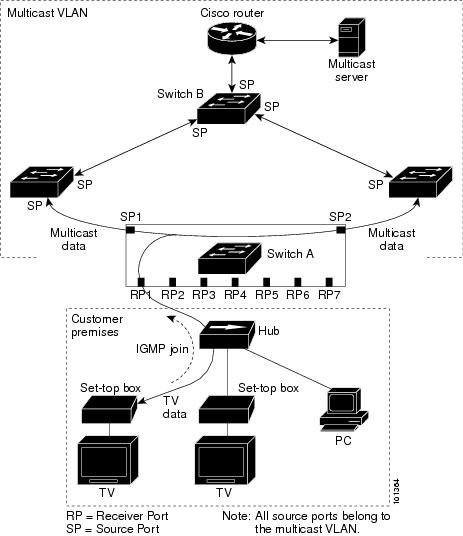
•![]() When a subscriber changes channels or switches off the television, the set-top box sends an IGMP leave message to the multicast stream. The SP CPU sends a MAC-based general query through the receiver port VLAN. If there is another set-top box in the VLAN still subscribing to this group, that set-top box must respond within the maximum response time specified in the query. If the CPU does not receive a response, it eliminates the receiver port as a forwarding destination for this group.
When a subscriber changes channels or switches off the television, the set-top box sends an IGMP leave message to the multicast stream. The SP CPU sends a MAC-based general query through the receiver port VLAN. If there is another set-top box in the VLAN still subscribing to this group, that set-top box must respond within the maximum response time specified in the query. If the CPU does not receive a response, it eliminates the receiver port as a forwarding destination for this group.
•![]() Unless the Immediate Leave feature is enabled, when the router receives an IGMP leave message from a subscriber on a receiver port, it sends out an IGMP query on that port and waits for IGMP group membership reports. If no reports are received in a configured time period, the receiver port is removed from multicast group membership. With the Immediate Leave feature enabled, an IGMP query is not sent from the receiver port on which the IGMP leave was received. As soon as the leave message is received, the receiver port is removed from multicast group membership, which speeds up leave latency. Enable the Immediate Leave feature only on receiver ports to which a single receiver device is connected.
Unless the Immediate Leave feature is enabled, when the router receives an IGMP leave message from a subscriber on a receiver port, it sends out an IGMP query on that port and waits for IGMP group membership reports. If no reports are received in a configured time period, the receiver port is removed from multicast group membership. With the Immediate Leave feature enabled, an IGMP query is not sent from the receiver port on which the IGMP leave was received. As soon as the leave message is received, the receiver port is removed from multicast group membership, which speeds up leave latency. Enable the Immediate Leave feature only on receiver ports to which a single receiver device is connected.
•![]() MVR eliminates the need to duplicate television-channel multicast traffic for subscribers in each VLAN. Multicast traffic for all channels is only sent around the VLAN trunk once—only on the multicast VLAN. The IGMP leave and join messages are in the VLAN to which the subscriber port is assigned. These messages dynamically register for streams of multicast traffic in the multicast VLAN on the layer 3 device, Switch B. The access layer switch, Switch A, modifies the forwarding behavior to allow the traffic to be forwarded from the multicast VLAN to the subscriber port in a different VLAN, selectively allowing traffic to cross between two VLANs.
MVR eliminates the need to duplicate television-channel multicast traffic for subscribers in each VLAN. Multicast traffic for all channels is only sent around the VLAN trunk once—only on the multicast VLAN. The IGMP leave and join messages are in the VLAN to which the subscriber port is assigned. These messages dynamically register for streams of multicast traffic in the multicast VLAN on the layer 3 device, Switch B. The access layer switch, Switch A, modifies the forwarding behavior to allow the traffic to be forwarded from the multicast VLAN to the subscriber port in a different VLAN, selectively allowing traffic to cross between two VLANs.
•![]() IGMP reports are sent to the same IP multicast group address as the multicast data. The Switch A CPU must capture all IGMP join and leave messages from receiver ports and forward them to the multicast VLAN of the source (uplink) port.
IGMP reports are sent to the same IP multicast group address as the multicast data. The Switch A CPU must capture all IGMP join and leave messages from receiver ports and forward them to the multicast VLAN of the source (uplink) port.
Configuring MVR
For information on configuring and troubleshooting the MVR, see: http://www.cisco.com/en/US/docs/routers/7600/ios/15S/configuration/guide/snooigmp.html
Configuring Layer 3 and Layer 4 Features
This section provides information about configuring Layer 3 and Layer 4 features on the Cisco 7600 Series ES20 line card on the Cisco 7600 series router. It includes the following topic:
•![]() Configuring Layer 3 and Layer 4 Access Control List on a Service Instance
Configuring Layer 3 and Layer 4 Access Control List on a Service Instance
For more information about the commands used in this chapter, see the Cisco IOS Release 12.2 SR Command References at http://www.cisco.com/en/US/docs/routers/7600/ios/12.2SR/configuration/guide/swcg.html.
Configuring Layer 3 and Layer 4 Access Control List on a Service Instance
An Access Control List (ACL) is a series of rules with ACEs (Access Control Elements). These ACEs define the network traffic profile, and permit or deny network traffic to Layer 3 or 4. You can use sequential ACL rules to filter network traffic. Each rule contains a filter element based on source address, destination address, protocol, and ports. For more information on the supported criteria, refer Table 2-24.
Layer 3 and Layer 4 ACL on Service Instance feature permits you to configure ACLs within an Ethernet Virtual Circuit (EVC) on the Cisco 7600 Series ES20 line cards. For more detailed information on the commands used this section, see Cisco IOS Security Configuration Guide, Release 12.2SR at
Table 2-24 maps the Layer 3 and 4 ACL criterion.
Table 2-24
Supported Layers versus Criterion
Restrictions and Usage Guidelines
When configuring the Layer 3 and Layer 4 ACLs on a Cisco 7600 Series ES20 line cards, follow these restrictions and usage guidelines:
•![]() L3 and L4 ACLs are supported only in ingress.
L3 and L4 ACLs are supported only in ingress.
•![]() You cannot simultaneously apply L2 ACL or L3/L4 ACLs on an EVC. You can either apply a L2 ACL, or a L3/L4 ACL within an EVC.
You cannot simultaneously apply L2 ACL or L3/L4 ACLs on an EVC. You can either apply a L2 ACL, or a L3/L4 ACL within an EVC.
•![]() L3 and L4 ACLs are not supported on EVCs in port-channels.
L3 and L4 ACLs are not supported on EVCs in port-channels.
•![]() IPv6 ACLs are not supported.
IPv6 ACLs are not supported.
•![]() Per ACE counters are not supported.
Per ACE counters are not supported.
•![]() You can apply a maximum of 4000 unique ACLs.
You can apply a maximum of 4000 unique ACLs.
•![]() You can configure a maximum of 8000 ACEs in a ES20 line card.
You can configure a maximum of 8000 ACEs in a ES20 line card.
•![]() In a L3 or L4 ACLs, if you apply the ACL name or number without actually creating the ACL, all the packets are permitted. However, in L2 ACLs, if you apply the ACL name,the packets are dropped.
In a L3 or L4 ACLs, if you apply the ACL name or number without actually creating the ACL, all the packets are permitted. However, in L2 ACLs, if you apply the ACL name,the packets are dropped.
•![]() For eq and neq L4 operators, a maximum of 10 ports are used to relay the parameters. However, you can apply the ACLs only on the first port.
For eq and neq L4 operators, a maximum of 10 ports are used to relay the parameters. However, you can apply the ACLs only on the first port.
•![]() Though the ACEs contain many rules based on which network traffic is filtered, only the criterion listed in Table 2-24 are supported.
Though the ACEs contain many rules based on which network traffic is filtered, only the criterion listed in Table 2-24 are supported.
SUMMARY STEPS TO CREATE A STANDARD L3 or L4 ACL
1. ![]() enable
enable
2. ![]() configure terminal
configure terminal
3. ![]() ip access-list standard {access-list-number | access-list-name}
ip access-list standard {access-list-number | access-list-name}
4. ![]() permit {source [source-wildcard] | any}
permit {source [source-wildcard] | any}
5. ![]() exit
exit
DETAILED STEPS TO CREATE A STANDARD L3 or L4 ACL
SUMMARY STEPS TO CREATE A NON UDP or TCP EXTENDED LIST
1. ![]() enable
enable
2. ![]() configure terminal
configure terminal
3. ![]() ip access-list extended {access-list-number|access-list-name}
ip access-list extended
{access-list-number|access-list-name}
4. ![]() [sequence-number] deny|permit protocol source source-wildcard destination destination-wildcard [[precedence precedence] [tos tos] | dscp dscp] [fragments]
[sequence-number] deny|permit protocol
source source-wildcard destination
destination-wildcard [[precedence
precedence] [tos tos]  | dscp dscp]
[fragments]
5. ![]() Repeat Step 4 as necessary
Repeat Step 4 as necessary
6. ![]() end
end
7. ![]() show ip access-lists {name|number}
show ip access-lists {name|number}
DETAILED STEPS TO CREATE CREATE A NON UDP or TCP EXTENDED LIST
SUMMARY STEPS TO CREATE A TCP and UDP BASED EXTENDED LIST
1. ![]() enable
enable
2. ![]() configure terminal
configure terminal
3. ![]() ip access-list extended access-list-name
ip access-list extended access-list-name
4. ![]() [sequence-number] {permit|deny} {tcp|udp} source source-wildcard [operator [port]] destination destination-wildcard [operator [port]] [precedence precedence] [tos tos] [fragments]
[sequence-number] {permit|deny} {tcp|udp} source source-wildcard [operator [port]] destination destination-wildcard [operator [port]] [precedence precedence] [tos tos] [fragments]
5. ![]() Repeat Step 4 as necessary, adding statements by sequence number where you planned. Use the no sequence-number command to delete an entry.
Repeat Step 4 as necessary, adding statements by sequence number where you planned. Use the no sequence-number command to delete an entry.
6. ![]() end
end
7. ![]() show ip access-lists {name|number}
show ip access-lists {name|number}
DETAILED STEPS TO CREATE A A TCP and UDP BASED EXTENDED LIST
SUMMARY STEPS TO APPLY A L3 or L4 ACL
1. ![]() enable
enable
2. ![]() configure terminal
configure terminal
3. ![]() interface gigabitethernet type/ slot/port
interface gigabitethernet type/ slot/port
4. ![]() service instance id Ethernet
service instance id Ethernet
5. ![]() ip access-group {list name|number} in
ip access-group {list name|number} in
6. ![]() exit
exit
DETAILED STEPS TO APPLY A L3 or L4 ACL
Examples
You can view the L3/L4 ACL counters for an EVC as shown in the following example:
7600bb# sh access-list test
Extended IP access list test
10 permit udp any host 1.2.3.4 eq 5
7600bb#sh run int gi 13/0/5
Building configuration...
Current configuration : 186 bytes
!
interface GigabitEthernet13/0/5
no ip address
no mls qos trust
service instance 1 ethernet
encapsulation dot1q 100
ip access-group test in
bridge-domain 100
!
end
7600bb# show ethernet service instance interface gigabitEthernet 13/0/5 detail
Service Instance ID: 1
Associated Interface: GigabitEthernet13/0/5
Associated EVC:
L2protocol drop
CE-Vlans:
Encapsulation: dot1q 100 vlan protocol type 0x8100
Interface Dot1q Tunnel Ethertype: 0x8100
State: Up
EFP Statistics:
Pkts In Bytes In Pkts Out Bytes Out
0 0 0 0
SACL permit in count: 0
SACL deny in count: 0
EFP Microblocks:
****************
Microblock type: Bridge-domain
Bridge-domain: 100
7600bb#show ethernet service instance interface gigabitEthernet 13/0/5 stats
Port maximum number of service instances: 8000
Service Instance 1, Interface GigabitEthernet13/0/5
Pkts In Bytes In Pkts Out Bytes Out
0 0 0 0
SACL permit in count: 0
SACL deny in count: 0
VRF aware IPv6 tunnel
The current IPv6 tunneling feature on c7600 does not support Virtual Routing and Forwarding (VRF) awareness. The forwarding table lookups for IPv6 overlay addresses and IPv4 transport addresses are performed in the global routing tables. This feature extends the tunneling support for IPv6 overlay addresses in VRF.
These scenarios explain the VRF aware IPv6 tunnel function:
•![]() IPv6 overlay address in VRF and IPv4 transport address in Global routing table (RT).
IPv6 overlay address in VRF and IPv4 transport address in Global routing table (RT).
•![]() IPv6 overlay address in VRF and IPv4 transport address in VRF.
IPv6 overlay address in VRF and IPv4 transport address in VRF.
Figure 2-9 illustrates the topology for the IPv6 overlay address in VRF, and the IPv4 transport address in VRF.
Figure 2-9 Topology for VRF aware IPv6 Tunnel
The VRF Aware IPv6 over IPv4 Tunnel can have any line card towards the core facing side.
.
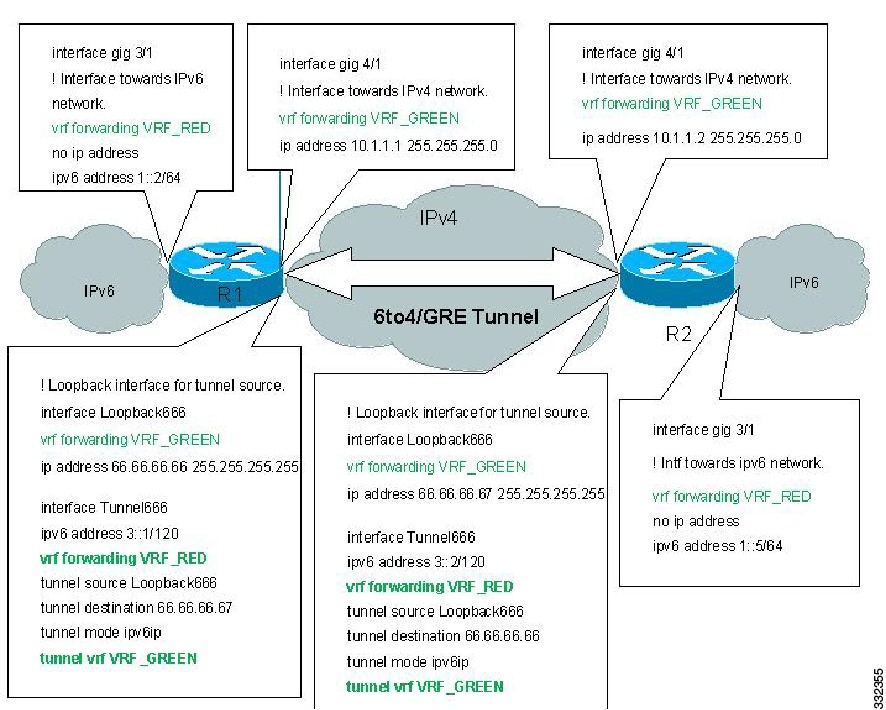
Restrictions for VRF aware IPv6 tunnels
Following restrictions apply to the VRF aware IPv6 tunnels feature:
•![]() This feature supports the IPv6IP and 6to4 tunnels mode.
This feature supports the IPv6IP and 6to4 tunnels mode.
•![]() Due to EARL limitation, the same source tunnels across VRFs are not supported.
Due to EARL limitation, the same source tunnels across VRFs are not supported.
•![]() The tunnel source and the tunnel destination should be in the same VRF instance.
The tunnel source and the tunnel destination should be in the same VRF instance.
•![]() The tunnel IPv4 transport addresses and the physical interface where the tunnel traffic exits, should be in the same VRF instance.
The tunnel IPv4 transport addresses and the physical interface where the tunnel traffic exits, should be in the same VRF instance.
•![]() The incoming IPv6 interface and the tunnel should be in the same VRF instance.
The incoming IPv6 interface and the tunnel should be in the same VRF instance.
•![]() This feature does not support IPv6IP auto-tunnels and ISATAP.
This feature does not support IPv6IP auto-tunnels and ISATAP.
Configuring VRF aware IPv6 tunnel
The following sections describe how to configure VRF aware IPv6 tunnel on c7600:
•![]() Configure IPv6 overlay addresses in VRF and IPv4 transport addresses in Global RT
Configure IPv6 overlay addresses in VRF and IPv4 transport addresses in Global RT
•![]() Configure IPv6 overlay addresses in VRF and IPv4 transport addresses in VRF
Configure IPv6 overlay addresses in VRF and IPv4 transport addresses in VRF
Configure IPv6 overlay addresses in VRF and IPv4 transport addresses in Global RT
Complete the following steps to configure IPv6 overlay addresses in VRF and IPv4 transport addresses in Global RT:
SUMMARY STEPS
Step 1 ![]() enable
enable
Step 2 ![]() configure terminal
configure terminal
Step 3 ![]() ipv6 unicast-routing
ipv6 unicast-routing
Step 4 ![]() mls ipv6 vrf
mls ipv6 vrf
Step 5 ![]() vrf definition vrf name
vrf definition vrf name
Step 6 ![]() rd {ASN:nn | IP address: nn}
rd {ASN:nn | IP address: nn}
Step 7 ![]() route-target [import | export | both]{ASN:nn | IP address: nn}
route-target [import | export | both]{ASN:nn | IP address: nn}
Step 8 ![]() address-family ipv6
address-family ipv6
Step 9 ![]() exit
exit
Step 10 ![]() address-family ipv4
address-family ipv4
Step 11 ![]() exit
exit
Step 12 ![]() exit
exit
Step 13 ![]() interface gigabitethernet slot/subslot/port
interface gigabitethernet slot/subslot/port
Step 14 ![]() vrf forwarding vrf name
vrf forwarding vrf name
Step 15 ![]() ipv6 address {ipv6-address/prefix-length | prefix-name sub-bits/prefix-length}
ipv6 address {ipv6-address/prefix-length | prefix-name sub-bits/prefix-length}
Step 16 ![]() exit
exit
Step 17 ![]() interface gigabitethernet slot/subslot/port
interface gigabitethernet slot/subslot/port
Step 18 ![]() ip address ip-address
ip address ip-address
Step 19 ![]() exit
exit
Step 20 ![]() interface loopback interface-number
interface loopback interface-number
Step 21 ![]() ip address ip-address
ip address ip-address
Step 22 ![]() exit
exit
Step 23 ![]() interface tunnel tunnel-number
interface tunnel tunnel-number
Step 24 ![]() vrf forwarding vrf name
vrf forwarding vrf name
Step 25 ![]() ipv6 address {ipv6-address/prefix-length | prefix-name sub-bits/prefix-length}
ipv6 address {ipv6-address/prefix-length | prefix-name sub-bits/prefix-length}
Step 26 ![]() tunnel source {ip-address | interface-type interface-number}
tunnel source {ip-address | interface-type interface-number}
Step 27 ![]() tunnel destination {hostname | ip-address | ipv6-address}
tunnel destination {hostname | ip-address | ipv6-address}
Step 28 ![]() tunnel mode ipv6ip
tunnel mode ipv6ip
Step 29 ![]() end
end
DETAILED STEPS
Configuration Example
This example shows how to configure the IPv6 overlay addresses in VRF, and the IPv4 transport addresses in the Global Routing Table:
Router# enable
Router# configure terminal
Router(config)# ipv6 unicast-routing
Router(config)# mls ipv6 vrf
Router(config)# vrf definition VRF_RED
Router(config-vrf)# rd 1:1
Router(config-vrf)# route-target export 1:1
Router(config-vrf)# route-target import 1:1
Router(config-vrf)# address-family ipv6
Router(config-vrf-af)# exit
Router(config-vrf)# address-family ipv4
Router(config-vrf)# (config-vrf-af)# exit
Router(config-vrf)# exit
Router(config)# interface gigabitethernet 3/0/1
Router(config-if)# vrf forwarding VRF_RED
Router(config-if)# ipv6 address 1::2/64
Router(config-if)# exit
Router(config)# interface gigabitethernet 4/0/1
Router(config-if)# ip address 10.1.1.1 255.255.255.0
Router(config-if)# exit
Router(config)# interface Loopback 666
Router(config-if)# ip address 66.66.66.66 255.255.255.255
Router(config-if)# exit
Router(config)# interface tunnel 666
Router(config-if)# vrf forwarding VRF_RED
Router(config-if)# ipv6 address 3::1/120
Router(config-if)# tunnel source loopback 666
Router(config-if)# tunnel destination 10.66.66.1
Router(config-if)# tunnel mode ipv6ip
Router(config-if)# end
Configure IPv6 overlay addresses in VRF and IPv4 transport addresses in VRF
Complete the following steps to configure IPv6 overlay addresses in VRF, and IPv4 transport addresses in VRF:
SUMMARY STEPS
Step 1 ![]() enable
enable
Step 2 ![]() configure terminal
configure terminal
Step 3 ![]() ipv6 unicast-routing
ipv6 unicast-routing
Step 4 ![]() mls ipv6 vrf
mls ipv6 vrf
Step 5 ![]() vrf definition vrf name 1
vrf definition vrf name 1
Step 6 ![]() rd {ASN:nn | IP address: nn}
rd {ASN:nn | IP address: nn}
Step 7 ![]() route-target [import | export | both] {ASN:nn | IP address: nn}
route-target [import | export | both] {ASN:nn | IP address: nn}
Step 8 ![]() address-family ipv6
address-family ipv6
Step 9 ![]() exit
exit
Step 10 ![]() address-family ipv4
address-family ipv4
Step 11 ![]() exit
exit
Step 12 ![]() exit
exit
Step 13 ![]() vrf definition vrf name 2
vrf definition vrf name 2
Step 14 ![]() rd {ASN:nn | IP address: nn}
rd {ASN:nn | IP address: nn}
Step 15 ![]() route-target [import | export | both] {ASN:nn | IP address: nn}
route-target [import | export | both] {ASN:nn | IP address: nn}
Step 16 ![]() address-family ipv4
address-family ipv4
Step 17 ![]() exit
exit
Step 18 ![]() exit
exit
Step 19 ![]() interface gigabitethernet slot/subslot/port
interface gigabitethernet slot/subslot/port
Step 20 ![]() vrf forwarding vrf name 1
vrf forwarding vrf name 1
Step 21 ![]() ipv6 address {ipv6-address/prefix-length | prefix-name sub-bits/prefix-length}
ipv6 address {ipv6-address/prefix-length | prefix-name sub-bits/prefix-length}
Step 22 ![]() exit
exit
Step 23 ![]() interface gigabitethernet slot/subslot/port
interface gigabitethernet slot/subslot/port
Step 24 ![]() vrf forwarding vrf name 2
vrf forwarding vrf name 2
Step 25 ![]() ip address ip-address
ip address ip-address
Step 26 ![]() exit
exit
Step 27 ![]() interface loopback interface-number
interface loopback interface-number
Step 28 ![]() vrf forwarding vrf name 2
vrf forwarding vrf name 2
Step 29 ![]() ip address ip-address
ip address ip-address
Step 30 ![]() exit
exit
Step 31 ![]() interface tunnel tunnel-number
interface tunnel tunnel-number
Step 32 ![]() vrf forwarding vrf name 1
vrf forwarding vrf name 1
Step 33 ![]() ipv6 address {ipv6-address/prefix-length | prefix-name sub-bits/prefix-length}
ipv6 address {ipv6-address/prefix-length | prefix-name sub-bits/prefix-length}
Step 34 ![]() tunnel source {ip-address | interface-type interface-number}
tunnel source {ip-address | interface-type interface-number}
Step 35 ![]() tunnel destination {hostname | ip-address | ipv6-address}
tunnel destination {hostname | ip-address | ipv6-address}
Step 36 ![]() tunnel mode ipv6ip
tunnel mode ipv6ip
Step 37 ![]() tunnel vrf vrf name 2
tunnel vrf vrf name 2
Step 38 ![]() end
end
DETAILED STEPS
Configuration Example
This example shows how to configure the IPv6 overlay addresses in VRF, and the IPv4 transport addresses in VRF:
Router# enable
Router# configure terminal
Router(config)# ipv6 unicast-routing
Router(config)# mls ipv6 vrf
Router(config)# vrf definition VRF_RED
Router(config-vrf)# rd 1:1
Router(config-vrf)# route-target export 1:1
Router(config-vrf)# route-target import 1:1
Router(config-vrf)# address-family ipv6
Router(config-vrf-af)# exit
Router(config-vrf)# address-family ipv4
Router(config-vrf-af)# exit
Router(config-vrf)# exit
Router(config)# vrf definition VRF_GREEN
Router(config-vrf)# rd 1:1
Router(config-vrf)# route-target export 1:1
Router(config-vrf)# route-target import 1:1
Router(config-vrf)# address-family ipv4
Router(config-vrf-af)# exit
Router(config-vrf)# exit
Router(config)# interface gigabitethernet 3/0/1
Router(config-if)# vrf forwarding VRF_RED
Router(config-if)# ipv6 address 1::2/64
Router(config-if)# exit
Router(config)# interface gigabitethernet 4/0/1
Router(config-if)# vrf forwarding VRF_GREEN
Router(config-if)# ip address 10.1.1.1 255.255.255.0
Router(config-if)# exit
Router(config)# interface Loopback 666
Router(config-if)# vrf forwarding VRF_GREEN
Router(config-if)# ip address 66.66.66.66 255.255.255.255
Router(config-if)# exit
Router(config)# interface tunnel 666
Router(config-if)# vrf forwarding VRF_RED
Router(config-if)# ipv6 address 3::1/120
Router(config-if)# tunnel source loopback 666
Router(config-if)# tunnel destination 10.66.66.1
Router(config-if)# tunnel mode ipv6ip
Router(config-if)# tunnel vrf VRF_GREEN
Router(config-if)# end
Verifying the Configuration
Use these commands to verify the configuration of VRF aware IPv6 tunnel on c7600:
Router# show vrf vrf-red
Name Default RD Protocols Interfaces
vrf-red 100:1 ipv4,ipv6 Tu666
Router# show interface tunnel 666
Tunnel666 is up, line protocol is up
Hardware is Tunnel
Internet address is 80.1.1.1/24
MTU 17916 bytes, BW 100 Kbit/sec, DLY 50000 usec,
reliability 255/255, txload 1/255, rxload 1/255
Encapsulation TUNNEL, loopback not set
Keepalive not set
Tunnel source 66.66.66.66 (Loopback666), destination 66.66.66.65
Tunnel Subblocks:
src-track:
Tunnel666 source tracking subblock associated with Loopback666
          Set of tunnels with source Loopback666, 1 member (includes iterators), on
interface <OK>
Tunnel protocol/transport GRE/IP
Key disabled, sequencing disabled
Checksumming of packets disabled
Tunnel TTL 255, Fast tunneling enabled
Tunnel transport MTU 1476 bytes
Tunnel transmit bandwidth 8000 (kbps)
Tunnel receive bandwidth 8000 (kbps)
Last input 00:07:00, output 00:02:39, output hang never
Last clearing of "show interface" counters 00:07:19
Input queue: 0/75/0/0 (size/max/drops/flushes); Total output drops: 0
Queueing strategy: fifo
Output queue: 0/0 (size/max)
5 minute input rate 0 bits/sec, 0 packets/sec
5 minute output rate 0 bits/sec, 0 packets/sec
L2 Switched: ucast: 0 pkt, 0 bytes - mcast: 0 pkt, 0 bytes
L3 in Switched: ucast: 0 pkt, 0 bytes - mcast: 0 pkt, 0 bytes mcast
L3 out Switched: ucast: 0 pkt, 0 bytes mcast: 0 pkt, 0 bytes
20 packets input, 1944 bytes, 0 no buffer
Received 0 broadcasts (0 IP multicasts)
0 runts, 0 giants, 0 throttles
0 input errors, 0 CRC, 0 frame, 0 overrun, 0 ignored, 0 abort
26 packets output, 2504 bytes, 0 underruns
0 output errors, 0 collisions, 0 interface resets
0 unknown protocol drops
0 output buffer failures, 0 output buffers swapped out
Troubleshooting Tips
For troubleshooting information, contact Cisco Technical Assistance Center (TAC) at:
http://www.cisco.com/en/US/support/tsd_cisco_worldwide_contacts.html
IPv6 Policy Based Routing
IPv6 policy-based routing (PBR) provides a flexible mechanism to route packets and define policy for the traffic flows. It extends and complements the existing mechanisms provided by routing protocols. PBR also provides a basic packet-marking capability.
PBR performs the following tasks:
•![]() Classifies traffic based on extended access list criteria. It provides access to lists and then establishes the match criteria.
Classifies traffic based on extended access list criteria. It provides access to lists and then establishes the match criteria.
•![]() Sets IPv6 precedence bits and enables the network to differentiate classes of service.
Sets IPv6 precedence bits and enables the network to differentiate classes of service.
•![]() Routes packets to specific traffic-engineered paths. You can route the packets to allow a specific quality of service (QoS) through the network.
Routes packets to specific traffic-engineered paths. You can route the packets to allow a specific quality of service (QoS) through the network.
The Cisco 7600 Series Router implements this feature using the Earl7 forwarding engines capability to classify traffic through an Access Control List (ACL) Ternary Content Addressable Memory (TCAM) lookup. The ACL TCAM lookup classifies traffic based on the combination of a variety of Layer 3 and Layer 4 traffic parameters. Once classified, the ACL TCAM drives results for matching flows. The Feature Manager (FM) component converts the route map policy configured on an interface into a series of values, masks and results (VMRs) and programs these in the ACL TCAM.
Policy Based Routing
All packets received on a PBR-enabled interface are passed through enhanced packet filters known as route maps. Route maps are composed of statements that are marked as permit or deny, and they are interpreted in these ways:
•![]() If a packet matches all match statements for a route map that is marked as permit, the router subjects the packet to PBR using the set statements.
If a packet matches all match statements for a route map that is marked as permit, the router subjects the packet to PBR using the set statements.
•![]() If the packet matches any match statements for a route map that is marked as deny, the router does not subject the packet to PBR and forwards it normally.
If the packet matches any match statements for a route map that is marked as deny, the router does not subject the packet to PBR and forwards it normally.
•![]() If the statement is marked as permit and the packets do not match any route map statements, the router sends the packets back through the normal forwarding channels and performs destination-based routing.
If the statement is marked as permit and the packets do not match any route map statements, the router sends the packets back through the normal forwarding channels and performs destination-based routing.
Packet Matching
The IPv6 PBR match criterion for a sequence is specified through a combination of IPv6 access-lists and packet length operations. Match statements are evaluated first by the criteria specified in the match ipv6 address command and then by criteria specified in the match length command. Therefore, if both an ACL and a length statement are used, a packet is first subjected to an ACL match. Only packets that pass the ACL match are subjected to the length match. Finally, only packets that pass both the ACL and the length statement are policy routed.
Packet Forwarding Using Set Statements
PBR for IPv6 packet forwarding is controlled using a number of set statements in the PBR route map. Listed below are the forwarding actions in order of decreasing priority, and the manner in which these options are reflected in the result from the VMRs programmed in the ACL TCAM. When more than one kind of packet forwarding action is specified in a sequence, the one with the highest priority is chosen.
Table 2-25 Packet Forwarding Set Statements
Restrictions for IPv6 PBR
Following restrictions apply to the IPv6 PBR:
•![]() Match length is not supported in the hardware, and the PBR is applied to the software.
Match length is not supported in the hardware, and the PBR is applied to the software.
•![]() Packet marking actions are not supported in the hardware, and packets requiring marking due to PBR are punted to the software.
Packet marking actions are not supported in the hardware, and packets requiring marking due to PBR are punted to the software.
•![]() Set interface is supported in the hardware only for the serial interface. Other interfaces are supported on the software.
Set interface is supported in the hardware only for the serial interface. Other interfaces are supported on the software.
•![]() Packets containing an IPv6 hop-by-hop header need to be examined by the router and are punted to the software. Such packets are subjected to PBR in the software.
Packets containing an IPv6 hop-by-hop header need to be examined by the router and are punted to the software. Such packets are subjected to PBR in the software.
•![]() PBR policies using access-lists matching on IPv6 flow label, DSCP value and extension headers such as, routing, mobility, destination headers cannot be fully classified in the hardware, and are punted to the software after partial classification.
PBR policies using access-lists matching on IPv6 flow label, DSCP value and extension headers such as, routing, mobility, destination headers cannot be fully classified in the hardware, and are punted to the software after partial classification.
•![]() It is not possible to completely classify traffic in hardware, when access-lists matching on non compressible addresses are used. In such cases, the PBR is applied to the software.
It is not possible to completely classify traffic in hardware, when access-lists matching on non compressible addresses are used. In such cases, the PBR is applied to the software.
•![]() On Tycho based systems, fragment packets that require matching on layer 4 protocol are punted to the software .
On Tycho based systems, fragment packets that require matching on layer 4 protocol are punted to the software .
•![]() IPv6 PBR on SVI interfaces is applied to the software, and hardware provides only partial classification.
IPv6 PBR on SVI interfaces is applied to the software, and hardware provides only partial classification.
•![]() IPv6 PBR when applied to hardware will also be applied on packets destined to a router address.
IPv6 PBR when applied to hardware will also be applied on packets destined to a router address.
•![]() A set next-hop action where the next-hop is at the other end of a tunnel is not supported in the hardware.
A set next-hop action where the next-hop is at the other end of a tunnel is not supported in the hardware.
•![]() For set interface and set default interface, the interface should be a point-to-point one.
For set interface and set default interface, the interface should be a point-to-point one.
•![]() PBR is not applied to multicast traffic and the traffic destined to link local addresses.
PBR is not applied to multicast traffic and the traffic destined to link local addresses.
•![]() When there is no traffic flow, the TCAM entry does not change from punt to policy-route.
When there is no traffic flow, the TCAM entry does not change from punt to policy-route.
Configuring IPv6 PBR
To configure, verify and troubleshoot the IPv6 PBR, see: Configuring IPv6 PBR.
Configuring MPLS Features
This section describes the MPLS features that have ES20 line card-specific configuration guidelines.
This section includes the following topics:
•![]() Configuring Any Transport over MPLS
Configuring Any Transport over MPLS
•![]() Configuring MPLS Traffic Engineering Class-Based Tunnel Selection
Configuring MPLS Traffic Engineering Class-Based Tunnel Selection
•![]() Configuring Virtual Private LAN Service
Configuring Virtual Private LAN Service
Configuring Any Transport over MPLS
Any Transport over MPLS (AToM) transports Layer 2 packets over a Multiprotocol Label Switching (MPLS) backbone. AToM uses a directed Label Distribution Protocol (LDP) session between edge routers for setting up and maintaining connections. Forwarding occurs through the use of two levels of labels, switching between the edge routers. The external label (tunnel label) routes the packet over the MPLS backbone to the egress Provider Edge (PE) at the ingress PE. The VC label is a demuxing label that determines the connection at the tunnel endpoint (the particular egress interface on the egress PE as well as the virtual path identifier [VPI]/virtual channel identifier [VCI] value for an ATM Adaptation Layer 5 [AAL5] protocol data unit [PDU], the data-link connection identifier [DLCI] value for a Frame Relay PDU, or the virtual LAN [VLAN] identifier for an Ethernet frame).
Scalable EoMPLS on 7600-ESM-2X10GE and 7600-ESM-20X1GE
The Scalable EoMPLS on 7600-ESM-2X10GE and 7600-ESM-20X1GE feature improves EoMPLS scalability on the Cisco 7600 router. With Scalable EoMPLS, the CE-facing line card performs all EoMPLS imposition and disposition label processing. From the core-side line card perspective, the AToM packets in and out of the router appear as generic MPLS frames.
Restrictions and Usage Guidelines
When configuring the Scalable EoMPLS on 7600-ESM-2X10GE and 7600-ESM-20X1GE feature, follow these restrictions and usage guidelines:
•![]() Scalable EoMPLS is supported with EVCs (Ethernet Virtual Circuits). An EVC is an end-to-end representation of a single instance of a layer 2 service being offered by a provider to a customer.
Scalable EoMPLS is supported with EVCs (Ethernet Virtual Circuits). An EVC is an end-to-end representation of a single instance of a layer 2 service being offered by a provider to a customer.
•![]() Scalable EoMPLS is supported as a mapped service for the QinQ termination
Scalable EoMPLS is supported as a mapped service for the QinQ termination
•![]() Service Instances supported- 16, 000 per line card (32, 000 per Cisco 7600 series router)
Service Instances supported- 16, 000 per line card (32, 000 per Cisco 7600 series router)
•![]() VC type 4 and VC type 5 are supported.
VC type 4 and VC type 5 are supported.
•![]() Control word operation is supported.
Control word operation is supported.
•![]() For ingress policing, only the drop action and the accept action for the police command are supported.
For ingress policing, only the drop action and the accept action for the police command are supported.
•![]() Ingress CoS marking is not supported.
Ingress CoS marking is not supported.
•![]() For QoS marking, mapping of the incoming VLAN dot1q p-bits to the outgoing MPLS EXP bits is supported.
For QoS marking, mapping of the incoming VLAN dot1q p-bits to the outgoing MPLS EXP bits is supported.
•![]() For QoS marking, mapping of the incoming MPLS EXP bits to the outgoing VLAN dot1q p-bits is supported.
For QoS marking, mapping of the incoming MPLS EXP bits to the outgoing VLAN dot1q p-bits is supported.
•![]() For QoS shaping, egress pseudowire shaping is supported. Matching is based on the MPLS EXP bits.
For QoS shaping, egress pseudowire shaping is supported. Matching is based on the MPLS EXP bits.
•![]() The Dot1q Transparency for EoMPLS feature is supported.
The Dot1q Transparency for EoMPLS feature is supported.
SUMMARY STEPS
1. ![]() enable
enable
2. ![]() configure terminal
configure terminal
3. ![]() interface gigabitethernet slot/subslot/port[.subinterface-number] or interface tengigabitethernet slot/subslot/port[.subinterface-number]
interface gigabitethernet slot/subslot/port[.subinterface-number] or interface tengigabitethernet slot/subslot/port[.subinterface-number]
4. ![]() [no] service instance id {Ethernet [service-name}
[no] service instance id {Ethernet [service-name}
5. ![]() encapsulation dot1q vlad id
encapsulation dot1q vlad id
6. ![]() rewrite ingress tag {push {dot1q vlan-id | dot1q vlan-id second-dot1q vlan-id | dot1ad vlan-id dot1q vlan-id} | pop {1 | 2} | translate {1-to-1 {dot1q vlan-id | dot1ad vlan-id}| 2-to-1 dot1q vlan-id | dot1ad vlan-id}| 1-to-2 {dot1q vlan-id second-dot1q vlan-id | dot1ad vlan-id dot1q vlan-id} | 2-to-2 {dot1q vlan-id second-dot1q vlan-id | dot1ad vlan-id dot1q vlan-id}} [symmetric]
rewrite ingress tag {push {dot1q vlan-id | dot1q vlan-id second-dot1q vlan-id | dot1ad vlan-id dot1q vlan-id} | pop {1 | 2} | translate {1-to-1 {dot1q vlan-id | dot1ad vlan-id}| 2-to-1 dot1q vlan-id | dot1ad vlan-id}| 1-to-2 {dot1q vlan-id second-dot1q vlan-id | dot1ad vlan-id dot1q vlan-id} | 2-to-2 {dot1q vlan-id second-dot1q vlan-id | dot1ad vlan-id dot1q vlan-id}} [symmetric]
7. ![]() xconnect peer-id vc-id encapsulation mpls
xconnect peer-id vc-id encapsulation mpls
DETAILED STEPS
Examples
The following is an example of a basic configuration:
This is the customer-facing port at router 1.
Router(config)# interface TenGigabitEthernet1/0/1
Router(config-if)# service instance 100 ethernet
Router(config-if-srv)# encapsulation dot1q 100
Router(config-if-srv)# rewrite ingress tag translate 1-to-2 dot1q 5 second-dot1q 5
symmetric
Router(config-if-srv)# xconnect 2.2.2.2 100 encapsulation mpls
This is the global configuration at router 1.
Router(config)# interface loopback1
Router(config-if)# ip address 1.1.1.1 255.255.255.255
!MPLS core facing port
Router(config-if)# ip address 20.1.1.1 255.255.255.0
Router(config-if)# mpls label protocol ldp
Router(config-if)# mpls ip
This is the customer-facing port at router 2.
Router(config)# interface TenGigabitEthernet2/0/2
Router(config-if)# service instance 100 ethernet
Router(config-if-srv)# encapsulation dot1q 100
Router(config-if-srv)# rewrite ingress tag translate 1-to-2 dot1q 5 second-dot1q 5
symmetric
Router(config-if-srv)# xconnect 1.1.1.1 100 encapsulation mpls
This is the global configuration at router 2.
Router(config)# interface loopback1
Router(config-if)# ip address 2.2.2.2 255.255.255.255
!MPLS core facing port
Router(config-if)# ip address 20.1.1.2 255.255.255.0
Router(config-if)# mpls label protocol ldp
Router(config-if)# mpls ip
The following is an example of single tag VLAN configuration for tunneling a single VLAN service instance.
! Customer facing port
Router(config)# interface TenGigabitEthernet2/0/2
Router(config-if)# service instance 100 ethernet
Router(config-if-srv)# encapsulation dot1q 100
Router(config-if-srv)# rewrite ingress tag translate 1-to-2 dot1q 5 second-dot1q 5
symmetric
Router(config-if-srv)# xconnect 1.1.1.1 100 encapsulation mpls
The following is an example of double tag VLAN configuration for tunneling double tag VLAN frames.
! Customer facing port
Router(config)# interface TenGigabitEthernet2/0/2
Router(config-if)# service instance 100 ethernet
Router(config-if-srv)# encapsulation dot1q 100 second-dot1q 200
Router(config-if-srv)# rewrite ingress tag translate 2-to-2 dot1q 5 second-dot1q 5
symmetric
Router(config-if-srv)# xconnect 1.1.1.1 100 encapsulation mpls
The following is an example of a selective QinQ cross connect configuration.
! Customer facing port
Router(config)# interface TenGigabitEthernet2/0/2
Router(config-if)# service instance 100 ethernet
Router(config-if-srv)# encapsulation dot1q 10-20, 30, 50-60
Router(config-if-srv)# xconnect 1.1.1.1 100 encapsulation mpls
The following is an example of a port-based cross connect tunnel configuration that tunnels all incoming packets to the remote peer.
!All tag and non-tag packets aggregation
Router(config)# interface TenGigabitEthernet2/0/2
Router(config-if)# service instance 100 ethernet
Router(config-if-srv)# encapsulation default
Router(config-if-srv)# xconnect 1.1.1.1 100 encapsulation mpls
!All non-tag packets aggregation
Router(config)# interface TenGigabitEthernet2/0/2
Router(config-if)# service instance 100 ethernet
Router(config-if-srv)# encapsulation untagged
Router(config-if-srv)# xconnect 1.1.1.1 100 encapsulation mpls
Verification
Use the following commands can be used to verify operation.
.
Configuring MPLS Traffic Engineering Class-Based Tunnel Selection
Multiprotocol Label Switching (MPLS) Traffic Engineering (TE) Class-Based Tunnel Selection (CBTS) enables you to dynamically route and forward traffic with different class of service (CoS) values onto different TE tunnels between the same tunnel headend and the same tailend. The TE tunnels can be regular TE tunnels or DiffServ-aware TE (DS-TE) tunnels.
The set of TE (or DS-TE) tunnels from the same headend to the same tailend that you configure to carry different CoS values is referred to as a "tunnel bundle." Tunnels are "bundled" by creating a master tunnel and then attaching member tunnels to the master tunnel. After configuration, CBTS dynamically routes and forwards each packet into the tunnel that meets the following requirements:
•![]() Is configured to carry the CoS of the packet
Is configured to carry the CoS of the packet
•![]() Has the right tailend for the destination of the packet
Has the right tailend for the destination of the packet
Because CBTS offers dynamic routing over DS-TE tunnels and requires minimum configuration, it greatly eases deployment of DS-TE in large-scale networks.
CBTS can distribute all CoS values on eight different tunnels.
CBTS also allows the TE tunnels of a tunnel bundle to exit headend routers through different interfaces.
CBTS configuration involves performing the following tasks:
•![]() Creating multiple (DS-) TE tunnels with the same headend and tailend and indicating on each of these tunnels which CoSs are to be transported on the tunnel.
Creating multiple (DS-) TE tunnels with the same headend and tailend and indicating on each of these tunnels which CoSs are to be transported on the tunnel.
•![]() Creating a master tunnel, attaching the member tunnels to it, and making the master tunnel visible for routing.
Creating a master tunnel, attaching the member tunnels to it, and making the master tunnel visible for routing.
Restrictions and Usage Guidelines
When configuring MPLS Traffic Engineering Class-Based Tunnel Selection (CBTS), follow these restrictions and usage guidelines:
•![]() CBTS has the following prerequisites:
CBTS has the following prerequisites:
–![]() MPLS enabled on all tunnel interfaces
MPLS enabled on all tunnel interfaces
–![]() Cisco Express Forwarding (CEF) or distributed CEF (dCEF) enabled in general configuration mode
Cisco Express Forwarding (CEF) or distributed CEF (dCEF) enabled in general configuration mode
•![]() CBTS has the following restrictions:
CBTS has the following restrictions:
–![]() For a given destination, all CoS values are carried in tunnels terminating at the same tailend. Either all CoS values are carried in tunnels or no values are carried in tunnels. In other words, for a given destination, you cannot map some CoS values in a DS-TE tunnel and other CoS values in a Shortest Path First (SPF) Label Distribution Protocol (LDP) or SPF IP path.
For a given destination, all CoS values are carried in tunnels terminating at the same tailend. Either all CoS values are carried in tunnels or no values are carried in tunnels. In other words, for a given destination, you cannot map some CoS values in a DS-TE tunnel and other CoS values in a Shortest Path First (SPF) Label Distribution Protocol (LDP) or SPF IP path.
–![]() No LSP is established for the master tunnel and regular traffic engineering attributes (bandwidth, path option, fast reroute) are irrelevant on a master tunnel. TE attributes (bandwidth, bandwidth pool, preemption, priorities, path options, and so on) are configured completely independently for each tunnel.
No LSP is established for the master tunnel and regular traffic engineering attributes (bandwidth, path option, fast reroute) are irrelevant on a master tunnel. TE attributes (bandwidth, bandwidth pool, preemption, priorities, path options, and so on) are configured completely independently for each tunnel.
–![]() CBTS does not allow load-balancing of a given EXP value in multiple tunnels. If two or more tunnels are configured to carry a given experimental (EXP) value, CBTS picks one of these tunnels to carry this EXP value.
CBTS does not allow load-balancing of a given EXP value in multiple tunnels. If two or more tunnels are configured to carry a given experimental (EXP) value, CBTS picks one of these tunnels to carry this EXP value.
–![]() CBTS supports aggregate control of bumping (that is, it is possible to define default tunnels to be used if other tunnels go down. However, CBTS does not allow control of bumping if the default tunnel goes down. CBTS does not support finer-grain control of bumping. For example, if the voice tunnel goes down, redirect voice to T2, but if video goes down, redirect to T3.
CBTS supports aggregate control of bumping (that is, it is possible to define default tunnels to be used if other tunnels go down. However, CBTS does not allow control of bumping if the default tunnel goes down. CBTS does not support finer-grain control of bumping. For example, if the voice tunnel goes down, redirect voice to T2, but if video goes down, redirect to T3.
–![]() The operation of CBTS is not supported with Any Transport over MPLS (AToM), MPLS TE Automesh, or label-controlled (LC) ATM.
The operation of CBTS is not supported with Any Transport over MPLS (AToM), MPLS TE Automesh, or label-controlled (LC) ATM.
Creating Multiple MPLS Member TE or DS-TE Tunnels with the Same Headend and the Same Tailend
Perform the following task to create multiple MPLS member TE or DS-TE tunnels with the same headend and same tailend and to configure EXP values to be carried by each of these tunnels. The procedure begins in global configuration mode.
SUMMARY STEPS
1. ![]() interface tunnel number
interface tunnel number
2. ![]() ip unnumbered type number
ip unnumbered type number
3. ![]() tunnel destination {hostname | ip-address}
tunnel destination {hostname | ip-address}
4. ![]() tunnel mode mpls traffic-eng
tunnel mode mpls traffic-eng
5. ![]() tunnel mpls traffic-eng bandwidth [sub-pool | global] bandwidth
tunnel mpls traffic-eng bandwidth [sub-pool | global] bandwidth
6. ![]() tunnel mpls traffic-eng exp [list-of-exp-values] [default]
tunnel mpls traffic-eng exp [list-of-exp-values] [default]
7. ![]() exit
exit
DETAILED STEPS
Creating a Master Tunnel, Attaching Member Tunnels, and Making the Master Tunnel Visible
Perform the followings task to create a master tunnel, attach member tunnels to it, and make the master tunnel visible for routing. The procedure begins in global configuration mode.
Summary Steps
1. ![]() interface tunnel number
interface tunnel number
2. ![]() ip unnumbered type number
ip unnumbered type number
3. ![]() tunnel destination {hostname | ip-address}
tunnel destination {hostname | ip-address}
4. ![]() tunnel mode mpls traffic-eng exp-bundle master
tunnel mode mpls traffic-eng exp-bundle master
5. ![]() tunnel mode mpls traffic-eng exp-bundle member tunnel-id
tunnel mode mpls traffic-eng exp-bundle member tunnel-id
6. ![]() tunnel mpls traffic-eng autoroute announce
tunnel mpls traffic-eng autoroute announce
7. ![]() tunnel mpls traffic-eng autoroute metric {absolute | relative} value
tunnel mpls traffic-eng autoroute metric {absolute | relative} value
DETAILED STEPS
Note ![]() Alternatively, static routing could be used instead of autoroute to make the TE or DS-TE tunnels visible for routing.
Alternatively, static routing could be used instead of autoroute to make the TE or DS-TE tunnels visible for routing.
EXAMPLE
The following example shows how to configure Multiprotocol Label Switching (MPLS) Traffic Engineering (TE) Class-Based Tunnel Selection (CBTS). Tunnel1, Tunnel2, and Tunnel3 are member tunnels, and Tunnel4 is the master tunnel.
Router(config)# interface Tunnel1
Router(config-if)# ip unnumbered loopback0
Router(config-if)# interface destination 24.1.1.1
Router(config-if)# tunnel mode mpls traffic-eng
Router(config-if)# tunnel mpls traffic-eng bandwidth sub-pool 30000
Router(config-if)# tunnel mpls traffic-eng exp 5
Router(config)# interface Tunnel2
Router(config-if)# ip unnumbered loopback0
Router(config-if)# interface destination 24.1.1.1
Router(config-if)# tunnel mode mpls traffic-eng
Router(config-if)# tunnel mpls traffic-eng bandwidth 50000
Router(config-if)# tunnel mpls traffic-eng exp 3 4
Router(config)# interface Tunnel3
Router(config-if)# ip unnumbered loopback0
Router(config-if)# interface destination 24.1.1.1
Router(config-if)# tunnel mode mpls traffic-eng
Router(config-if)# tunnel mpls traffic-eng bandwidth 10000
Router(config-if)# tunnel mpls traffic-eng exp default
Router(config)# interface Tunnel4
Router(config-if)# interface destination 24.1.1.1
Router(config-if)# tunnel mpls traffic-eng exp-bundle master
Router(config-if)# tunnel mpls traffic-eng exp-bundle member Tunnel1
Router(config-if)# tunnel mpls traffic-eng exp-bundle member Tunnel2
Router(config-if)# tunnel mpls traffic-eng exp-bundle member Tunnel3
Router(config-if)# tunnel mpls traffic-eng autoroute enable
Verifying That the MPLS TE or DS-TE Tunnels Are Operating and Announced to the IGP
The following show commands can be used to verify that the MPLS TE or DS-TE tunnels are operating and announced to the IGP. The commands are all entered in privileged EXEC configuration mode.
The show mpls traffic-eng topology command output displays the MPLS TE global topology:
Router# show mpls traffic-eng topology 10.0.0.1
IGP Id: 10.0.0.1, MPLS TE Id:10.0.0.1 Router Node (ospf 10 area 0) id 1
link[0]: Broadcast, DR: 180.0.1.2, nbr_node_id:6, gen:18
frag_id 0, Intf Address:180.0.1.1
TE metric:1, IGP metric:1, attribute_flags:0x0
SRLGs: None
physical_bw: 100000 (kbps), max_reservable_bw_global: 1000 (kbps)
max_reservable_bw_sub: 0 (kbps)
Global Pool Sub Pool
Total Allocated Reservable Reservable
BW (kbps) BW (kbps) BW (kbps)
--------------- ----------- ----------
bw[0]: 0 1000 0
bw[1]: 0 1000 0
bw[2]: 0 1000 0
bw[3]: 0 1000 0
bw[4]: 0 1000 0
bw[5]: 0 1000 0
bw[6]: 0 1000 0
bw[7]: 100 900 0
link[1]: Broadcast, DR: 180.0.2.2, nbr_node_id:7, gen:19
frag_id 1, Intf Address:180.0.2.1
TE metric:1, IGP metric:1, attribute_flags:0x0
SRLGs: None
physical_bw: 100000 (kbps), max_reservable_bw_global: 1000 (kbps)
max_reservable_bw_sub: 0 (kbps)
Global Pool Sub Pool
Total Allocated Reservable Reservable
BW (kbps) BW (kbps) BW (kbps)
--------------- ----------- ----------
bw[0]: 0 1000 0
bw[1]: 0 1000 0
bw[2]: 0 1000 0
bw[3]: 0 1000 0
bw[4]: 0 1000 0
bw[5]: 0 1000 0
bw[6]: 0 1000 0
bw[7]: 0 1000 0
The show mpls traffic-eng exp command output displays EXP mapping information about a tunnel:
Router# show mpls traffic-eng exp
Destination: 10.0.0.9
Master: Tunnel10 Status: IP
Members: Status Conf EXP Actual EXP
Tunnel1 UP/ACTIVE 5 5
Tunnel2 UP/ACTIVE default 0 1 2 3 4 6 7
Tunnel3 UP/INACTIVE(T) 2
Tunnel4 DOWN 3
Tunnel5 UP/ACTIVE(NE)
(T)=Tailend is different to master
(NE)=There is no exp value configured on this tunnel.
The show ip cef detail command output displays detailed FIB entry information for a tunnel:
Router# show ip cef tunnel1 detail
IP CEF with switching (Table Version 46), flags=0x0
31 routes, 0 reresolve, 0 unresolved (0 old, 0 new), peak 2
2 instant recursive resolutions, 0 used background process
8 load sharing elements, 8 references
6 in-place/0 aborted modifications
34696 bytes allocated to the FIB table data structures
universal per-destination load sharing algorithm, id 9EDD49E1
1(0) CEF resets
Resolution Timer: Exponential (currently 1s, peak 1s)
Tree summary:
8-8-8-8 stride pattern
short mask protection disabled
31 leaves, 23 nodes using 26428 bytes
Table epoch: 0 (31 entries at this epoch)
Adjacency Table has 13 adjacencies
10.0.0.9/32, version 45, epoch 0, per-destination sharing
0 packets, 0 bytes
tag information set, all rewrites inherited
local tag: tunnel head
via 0.0.0.0, Tunnel1, 0 dependencies
traffic share 1
next hop 0.0.0.0, Tunnel1
valid adjacency
tag rewrite with Tu1, point2point, tags imposed {12304}
0 packets, 0 bytes switched through the prefix
tmstats: external 0 packets, 0 bytes
internal 0 packets, 0 bytes
The show mpls forwarding-table detail command output displays detailed information from the MPLS LFIB:
Router# show mpls forwarding 10.0.0.9 detail
Local Outgoing Prefix Bytes tag Outgoing Next Hop
tag tag or VC or Tunnel Id switched interface
Tun hd Untagged 10.0.0.9/32 0 Tu1 point2point
MAC/Encaps=14/18, MRU=1500, Tag Stack{12304}, via Fa6/0
00027D884000000ED70178A88847 03010000
No output feature configured
Per-exp selection: 1
Untagged 10.0.0.9/32 0 Tu2 point2point
MAC/Encaps=14/18, MRU=1500, Tag Stack{12305}, via Fa6/1
00027D884001000ED70178A98847 03011000
No output feature configured
Per-exp selection: 2 3
Untagged 10.0.0.9/32 0 Tu3 point2point
MAC/Encaps=14/18, MRU=1500, Tag Stack{12306}, via Fa6/1
00027D884001000ED70178A98847 03012000
No output feature configured
Per-exp selection: 4 5
Untagged 10.0.0.9/32 0 Tu4 point2point
MAC/Encaps=14/18, MRU=1500, Tag Stack{12307}, via Fa6/1
00027D884001000ED70178A98847 03013000
No output feature configured
Per-exp selection: 0 6 7
The show mpls traffic-eng autoroute command output displays tunnels that are announced to the Interior Gateway Protocol (IGP).
Router# show mpls traffic-eng autoroute
MPLS TE autorouting enabled
destination 10.0.0.9, area ospf 10 area 0, has 4 tunnels
Tunnel1 (load balancing metric 20000000, nexthop 10.0.0.9)
(flags: Announce)
Tunnel2 (load balancing metric 20000000, nexthop 10.0.0.9)
(flags: Announce)
Tunnel3 (load balancing metric 20000000, nexthop 10.0.0.9)
(flags: Announce)
Tunnel4 (load balancing metric 20000000, nexthop 10.0.0.9)
(flags: Announce)
Configuring Virtual Private LAN Service
Virtual Private LAN Service (VPLS) enables geographically separate LAN segments to be interconnected as a single bridged domain over a packet switched network, such as IP, MPLS, or a hybrid of both.
VPLS solves the network reconfiguration problems at the customer equipment (CE) that is associated with Layer 2 Virtual Private Network (L2VPN) implementations. The current Cisco IOS software L2VPN implementation builds a point-to-point connection to interconnect the two attachment VCs of two peering customer sites. To communicate directly among all sites of an L2VPN network, a distinct emulated VC needs to be created between each pair of peering attachment VCs.
For example, when two sites of the same L2VPN network are connected to the same PE, you must establish two separate emulated VCs towards a given remote site, instead of sharing a common emulated VC between these two sites. For an L2VPN customer who uses the service provider backbone to interconnect its LAN segments, the current implementation effectively turns its multiaccess broadcast network into a fully meshed point-to-point network, which requires extensive reconfiguration on the existing CE devices.
VPLS is a multipoint L2VPN architecture that connects two or more customer devices using EoMPLS bridging techniques. VPLS with EoMPLS uses an MPLS-based provider core, where the PE routers have to cooperate to forward customer Ethernet traffic for a given VPLS instance in the core.
VPLS uses the provider core to join multiple attachment circuits together to simulate a virtual bridge that connects the multiple attachment circuits together. From a customer point of view, there is no topology for VPLS. All of the CE devices appear to connect to a logical bridge emulated by the provider core.
Hierarchical Virtual Private LAN Service (H-VPLS) with MPLS to the Edge
In a flat or nonhierarchical VPLS configuration, a full mesh of pseudowires (PWs) is needed between all PE nodes. A pseudowire defines a VLAN and its corresponding pseudoport.
Hierarchical Virtual Private LAN Service (H-VPLS) reduces both signaling and replication overhead by using a combination of full-mesh and hub-and-spoke configurations. Hub-and-spoke configurations operate with split horizon to allow packets to be switched between PWs, which effectively reduce the number of PWs between PEs.
Figure 2-10 H-VPLS with MPLS to the Edge Network
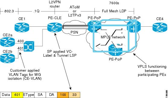
In the H-VPLS with MPLS to the edge architecture, Ethernet Access Islands (EAIs) work in combination with a VPLS core network, with MPLS as the underlying transport mechanism. EAIs operate like standard Ethernet networks. In Figure 2-10, devices CE1, CE2a and CE2b reside in an EAI. Traffic from any CE devices within the EAI is switched locally within the EAI by the user-facing provider edge (UPE) device along the computed spanning-tree path. Each UPE device is connected to one or more network-facing provider edge (NPE) devices using PWs. The traffic local to the UPE is not forwarded to any network-facing provider edge (NPE) devices.
VPLS Configuration Guidelines
When configuring VPLS on a Cisco 7600 Series Ethernet Services 20G line card, consider the following guidelines:
•![]() The Cisco 7600 Series Ethernet Services 20G line card supports up to 4000 VPLS domains per Cisco 7600 series router.
The Cisco 7600 Series Ethernet Services 20G line card supports up to 4000 VPLS domains per Cisco 7600 series router.
•![]() The Cisco 7600 Series Ethernet Services 20G line card supports up to 60 VPLS peers per domain per Cisco 7600 series router.
The Cisco 7600 Series Ethernet Services 20G line card supports up to 60 VPLS peers per domain per Cisco 7600 series router.
Note ![]() From Cisco IOS release12.2(33) SRD onwards, the Cisco 7600 Series Ethernet Services 20G line card supports up to 110 VPLS peers per domain per Cisco 7600 series router.
From Cisco IOS release12.2(33) SRD onwards, the Cisco 7600 Series Ethernet Services 20G line card supports up to 110 VPLS peers per domain per Cisco 7600 series router.
•![]() The Cisco 7600 Series Ethernet Services 20G line card supports up to 30,000 pseudowires, used in any combination of domains and peers up to the 4000-domain or 60-peer maximums. For example, support of up to 4000 domains with 7 peers, or up to 60 peers in 500 domains. However, although 30, 000 vcs are supported, these are not the recommended system operating limits.
The Cisco 7600 Series Ethernet Services 20G line card supports up to 30,000 pseudowires, used in any combination of domains and peers up to the 4000-domain or 60-peer maximums. For example, support of up to 4000 domains with 7 peers, or up to 60 peers in 500 domains. However, although 30, 000 vcs are supported, these are not the recommended system operating limits.
•![]() When configuring VPLS on a Cisco 7600 Series Ethernet Services 20G line card, consider the following guidelines:
When configuring VPLS on a Cisco 7600 Series Ethernet Services 20G line card, consider the following guidelines:
–![]() H-VPLS with QinQ edge—Requires a Cisco 7600 Series Ethernet Services 20G line card in the uplink, and any LAN port or Cisco 7600 Series Ethernet Services 20G line card on the downlink.
H-VPLS with QinQ edge—Requires a Cisco 7600 Series Ethernet Services 20G line card in the uplink, and any LAN port or Cisco 7600 Series Ethernet Services 20G line card on the downlink.
•![]() H-VPLS with MPLS edge requires either an optical service module, Cisco 7600 SIP-600, Cisco 7600 SIP-400, or Cisco 7600 Series Ethernet Services 20G line cards in both the downlink (facing UPE) and uplink (MPLS core).
H-VPLS with MPLS edge requires either an optical service module, Cisco 7600 SIP-600, Cisco 7600 SIP-400, or Cisco 7600 Series Ethernet Services 20G line cards in both the downlink (facing UPE) and uplink (MPLS core).
•![]() The Cisco 7600 Series Ethernet Services 20G line cards provide Transparent LAN Services (TLS) and Ethernet Virtual Connection Services (EVCS).
The Cisco 7600 Series Ethernet Services 20G line cards provide Transparent LAN Services (TLS) and Ethernet Virtual Connection Services (EVCS).
•![]() The Cisco 7600 Series Ethernet Services 20G line cards support the following VPLS features:
The Cisco 7600 Series Ethernet Services 20G line cards support the following VPLS features:
–![]() H-VPLS with MPLS edge
H-VPLS with MPLS edge
–![]() H-VPLS with QinQ edge
H-VPLS with QinQ edge
–![]() VPLS with point-to-multipoint EoMPLS and fully-meshed PE configuration
VPLS with point-to-multipoint EoMPLS and fully-meshed PE configuration
•![]() For information about configuring VPLS on the Cisco 7600 Series Ethernet Services 20G line cards, consider the guidelines in this document:
For information about configuring VPLS on the Cisco 7600 Series Ethernet Services 20G line cards, consider the guidelines in this document:
•![]() VPLS is supported only with intelligent cards as core facing cards. If both intelligent and non-intelligent cards are used as core facing cards, then route change events can cause VPLS VC to go over non-intelligent cards, and under such conditions, VPLS may not work as expected.
VPLS is supported only with intelligent cards as core facing cards. If both intelligent and non-intelligent cards are used as core facing cards, then route change events can cause VPLS VC to go over non-intelligent cards, and under such conditions, VPLS may not work as expected.
Configuring SVI-Based IP/Routed Interworking
Interworking interconnects two heterogeneous Attachment Circuits (ACs).
The types of interworking functions used depends on the following criteria:
•![]() AC types used.
AC types used.
•![]() Data type relayed.
Data type relayed.
•![]() Level of functions supported by the router.
Level of functions supported by the router.
The interworking functions currently supported are:
•![]() Bridged Interworking —Used with the Layer 2 (L2) packets regardless of the Layer 3 (L3) contents. The Internet Service Provider (ISP) do not participate in the routing.
Bridged Interworking —Used with the Layer 2 (L2) packets regardless of the Layer 3 (L3) contents. The Internet Service Provider (ISP) do not participate in the routing.
•![]() Ethernet Interworking— Used with a Ethernet (Port) over Multiprotocol Label Switching (MPLS) pseudowire for bridged interworking.
Ethernet Interworking— Used with a Ethernet (Port) over Multiprotocol Label Switching (MPLS) pseudowire for bridged interworking.
•![]() Routed Interworking—Used to relay L3 packets. There are different routed interworking for each protocol type. Internet Protocol (IP) Interworking or Switched Virtual Interface (SVI)/VLAN-based IP/Routed interworking uses IP over MPLS (Multiprotocol Label Switching) pseudowires to relay data.
Routed Interworking—Used to relay L3 packets. There are different routed interworking for each protocol type. Internet Protocol (IP) Interworking or Switched Virtual Interface (SVI)/VLAN-based IP/Routed interworking uses IP over MPLS (Multiprotocol Label Switching) pseudowires to relay data.
As Ethernet-to-Ethernet or PPP-to-PPP supports Layer 2 transport over MPLS and IP, L2VPN Interworking augments this functionality and connects disparate attachment circuits. Interworking function translates data between the different Layer 2 encapsulations. ES 20 line card supports IP routed interworking, also known as IP interworking.
Note ![]() If a Layer2 pseudowire is configured on an interface VLAN instead of the phisycal interface and the pseudowire traffic on Layer2 reaches the destination (core facing) through an ES20 line card, the PIM and IGMP traffic crossing the pseudowire is switched to the Route Processor (software switched) resulting in high CPU utilization. To enable hardware switching for the PIM and IGMP traffic, disable IGMP snooping.
If a Layer2 pseudowire is configured on an interface VLAN instead of the phisycal interface and the pseudowire traffic on Layer2 reaches the destination (core facing) through an ES20 line card, the PIM and IGMP traffic crossing the pseudowire is switched to the Route Processor (software switched) resulting in high CPU utilization. To enable hardware switching for the PIM and IGMP traffic, disable IGMP snooping.
In a Routed mode AToM (Any Transport over MPLS) interworking:
•![]() Address Resolution Protocol (ARP) is terminated on the ethernet PE.
Address Resolution Protocol (ARP) is terminated on the ethernet PE.
•![]() When the payload is sent to core, there is no ethernet header and cannot relay to the PE using Frame Relay or ATM.
When the payload is sent to core, there is no ethernet header and cannot relay to the PE using Frame Relay or ATM.
•![]() ATM or FR side does not handle L2 encapsulation.
ATM or FR side does not handle L2 encapsulation.
When you execute the interworking {ethernet | ip} command in pseudowire- class configuration mode:
•![]() The attachment circuits are locally terminated.
The attachment circuits are locally terminated.
•![]() The ethernet keyword removes the Ethernet frames from the attachment circuit, and relays them over the pseudowire.
The ethernet keyword removes the Ethernet frames from the attachment circuit, and relays them over the pseudowire.
•![]() Ethernet end-to-end transmission is assumed.
Ethernet end-to-end transmission is assumed.
•![]() Nonethernet attachment circuit frames are dropped.
Nonethernet attachment circuit frames are dropped.
•![]() The VLAN tag is removed, and the untagged Ethernet frame is retained.
The VLAN tag is removed, and the untagged Ethernet frame is retained.
Restrictions and Usage Guidelines
•![]() ES20 supports only SVI- based interworking.
ES20 supports only SVI- based interworking.
•![]() ES20 does not support ATM/FR/PPP.
ES20 does not support ATM/FR/PPP.
SUMMARY STEPS TO CONFIGURE Ethernet VLAN to ATM AAL5
1. ![]() enable
enable
2. ![]() configure terminal
configure terminal
3. ![]() pseudowire-class pw-class-name
pseudowire-class pw-class-name
4. ![]() encapsulation mpls
encapsulation mpls
5. ![]() interworking ip
interworking ip
6. ![]() vlan vlan-id
vlan vlan-id
7. ![]() interface vlan vlan-id
interface vlan vlan-id
8. ![]() no ip address
no ip address
9. ![]() xconnect destination-id vc-id pw-class pw-class-name
xconnect destination-id vc-id pw-class pw-class-name
10. ![]() exit
exit
DETAILED STEPS TO CONFIGURE Ethernet VLAN to ATM AAL5
Example
Use the following commands to configure Ethernet VLAN to ATM AAL5 on an SVI interface:
pseudowire-class pwc-mpls-ip
encapsulation mpls
interworking ip
!
vlan 119
!
interface Vlan119
no ip address
xconnect 12.205.2.2 119 pw-class pwc-mpls-ip
Verification
Use the show mpls l2 vc or show mpls l2 vc <vc-id> detail command to verify the status of the VC or the pseudowire.
Resetting a Cisco 7600 Series Ethernet Services 20G Line Card
To reset an ES20 line card, use the following command in privileged EXEC configuration mode:
SFP-GE-T Support
The SFP-GE-T on the Cisco 7600-ES20-GE line card supports speeds of 10 Mbps, 100 Mbps, and 1000 Mbps. Speed is not autonegotiated; you must configure it using the speed command. Only full-duplex mode is supported.
Note ![]() Auto negotiation of duplex mode is not supported, hence, manually configure the remote port for full-duplex mode.
Auto negotiation of duplex mode is not supported, hence, manually configure the remote port for full-duplex mode.
You can configure each Ethernet interface independently using any combination of 10 Mbps, 100 Mbps, or 1000 Mbps.
To set the interface speed, use the following command in the interface configuration mode.
 Feedback