- Managing Router Physical Entities
Using MIBs
This chapter describes how to perform tasks on the Cisco 7301 router.
•![]() Managing Router Physical Entities
Managing Router Physical Entities
–![]() Enabling Interface LinkUp/LinkDown Traps
Enabling Interface LinkUp/LinkDown Traps
–![]() SNMP Trap Filtering for linkDown Traps
SNMP Trap Filtering for linkDown Traps
•![]() Monitoring Quality of Service
Monitoring Quality of Service
•![]() Billing Customers for Traffic
Billing Customers for Traffic
Managing Router Physical Entities
This section describes how to use SNMP to manage the physical entities (components) in the router by:
•![]() Physical Entity Management MIBs
Physical Entity Management MIBs
•![]() Performing Inventory Management
Performing Inventory Management
•![]() Monitoring and Configuring FRU Status
Monitoring and Configuring FRU Status
Purpose and Benefits
The physical entity management feature of the Cisco 7301 SNMP implementation does the following:
•![]() Monitors and configures the status of field replaceable units (FRUs)
Monitors and configures the status of field replaceable units (FRUs)
•![]() Provides information about physical port to interface mappings
Provides information about physical port to interface mappings
•![]() Provides firmware and software information for chassis components
Provides firmware and software information for chassis components
The entPhysicalTable enumerates the physical entities contained by the system. In addition, it classifies each physical entity into a vendor type and class.

Note ![]() The sample outputs and values that appear throughout this chapter are only examples of what you can view when using MIBs.
The sample outputs and values that appear throughout this chapter are only examples of what you can view when using MIBs.
Physical Entity Management MIBs
The following MIBs are used to manage physical entities on the Cisco 7301:
•![]() CISCO-ENTITY-ASSET-MIB—Contains asset tracking information (ID PROM contents) for the physical entities listed in the entPhysicalTable of the ENTITY-MIB. The MIB provides device-specific information for physical entities, including orderable part number, serial number, manufacturing assembly number, and hardware, software, and firmware information.
CISCO-ENTITY-ASSET-MIB—Contains asset tracking information (ID PROM contents) for the physical entities listed in the entPhysicalTable of the ENTITY-MIB. The MIB provides device-specific information for physical entities, including orderable part number, serial number, manufacturing assembly number, and hardware, software, and firmware information.
•![]() CISCO-ENTITY-FRU-CONTROL-MIB—Contains objects used to monitor and configure the administrative and operational status of field replaceable units (FRUs), such as power supplies and line cards, that are listed in the entPhysicalTable of the ENTITY-MIB.
CISCO-ENTITY-FRU-CONTROL-MIB—Contains objects used to monitor and configure the administrative and operational status of field replaceable units (FRUs), such as power supplies and line cards, that are listed in the entPhysicalTable of the ENTITY-MIB.
•![]() CISCO-ENTITY-VENDORTYPE-OID-MIB—Contains the object identifiers (OIDs) for all physical entities in the router in the entPhysicalTable.
CISCO-ENTITY-VENDORTYPE-OID-MIB—Contains the object identifiers (OIDs) for all physical entities in the router in the entPhysicalTable.
•![]() CISCO-ENVMON-MIB—Contains information about the status of environmental sensors. For example, the MIB reports the chassis core inlet temperatures.
CISCO-ENVMON-MIB—Contains information about the status of environmental sensors. For example, the MIB reports the chassis core inlet temperatures.
•![]() ENTITY-MIB—Contains information for managing physical entities on the router. It also organizes the physical entities contained by a system into a tree, referred to as a containment tree. This tree describes the relationship of each physical entity to all others. The ENTITY-MIB contains the following tables:
ENTITY-MIB—Contains information for managing physical entities on the router. It also organizes the physical entities contained by a system into a tree, referred to as a containment tree. This tree describes the relationship of each physical entity to all others. The ENTITY-MIB contains the following tables:
–![]() The entPhysicalTable describes each physical component (entity) in the router. The table contains an entry for the top-level entity (the chassis) and for each entity in the chassis. Each entry provides information about that entity: its name, type, vendor, and a description, and describes how the entity fits into the hierarchy of chassis entities. Each entity is identified by a unique index (entPhysicalIndex) that is used to access information about the entity in this and other MIBs.
The entPhysicalTable describes each physical component (entity) in the router. The table contains an entry for the top-level entity (the chassis) and for each entity in the chassis. Each entry provides information about that entity: its name, type, vendor, and a description, and describes how the entity fits into the hierarchy of chassis entities. Each entity is identified by a unique index (entPhysicalIndex) that is used to access information about the entity in this and other MIBs.
The entPhysicalTable which contains two managed objects that describe a physical entity's relationship to its parent:
•![]() entPhysicalContainedIn - this object specifies the entPhysicalIndex of the physical entity representing this physical entity's parent; that is, the physical entity that contains this physical entity. For example, a physical entity representing a slot (within a chassis) typically contains a physical entity representing a line card. The slot is the parent of the line card.
entPhysicalContainedIn - this object specifies the entPhysicalIndex of the physical entity representing this physical entity's parent; that is, the physical entity that contains this physical entity. For example, a physical entity representing a slot (within a chassis) typically contains a physical entity representing a line card. The slot is the parent of the line card.
•![]() entPhysicalParentRelPos - this object specifies an integer value that represents this physical entity's relationship relative to its parent. For example, a physical entity representing a slot will have an entPhysicalParentRelPos equal to the slot number of the physical slot it represents.
entPhysicalParentRelPos - this object specifies an integer value that represents this physical entity's relationship relative to its parent. For example, a physical entity representing a slot will have an entPhysicalParentRelPos equal to the slot number of the physical slot it represents.
–![]() The entPhysicalContainsTable, which lists the children of each physical entity contained by the system. This table provides the management client with another view of the parent-child relationship between physical entities.
The entPhysicalContainsTable, which lists the children of each physical entity contained by the system. This table provides the management client with another view of the parent-child relationship between physical entities.
Performing Inventory Management
To obtain information about a particular physical entity in the Cisco 7301 router walk through the entPhysicalTable in the ENTITY-MIB. The entPhysicalDescr gives a textual description of the entity. Using the entPhysicalIndex that corresponds to the description of the entity, you can obtain other parameters.
Notes about entPhysicalTable Entries
As you examine entries in the ENTITY-MIB entPhysicalTable, consider the following:
•![]() entPhysicalIndex—Uniquely identifies each entity in the chassis. This index is also used to access information about the entity in other MIBs.
entPhysicalIndex—Uniquely identifies each entity in the chassis. This index is also used to access information about the entity in other MIBs.
•![]() entPhysicalContainedIn—Indicates the entPhysicalIndex of a component's parent entity.
entPhysicalContainedIn—Indicates the entPhysicalIndex of a component's parent entity.
•![]() entPhysicalParentRelPos—Shows the relative position of same-type entities that have the same entPhysicalContainedIn value (for example, chassis slots and line card ports).
entPhysicalParentRelPos—Shows the relative position of same-type entities that have the same entPhysicalContainedIn value (for example, chassis slots and line card ports).
Note ![]() The container is applicable if the physical entity class is capable of containing one or more removable physical entities. For example, each (empty or full) slot in a chassis will be modeled as a container. All removable physical entities should be modeled within a container entity, such as field-replaceable modules, fans, or power supplies.
The container is applicable if the physical entity class is capable of containing one or more removable physical entities. For example, each (empty or full) slot in a chassis will be modeled as a container. All removable physical entities should be modeled within a container entity, such as field-replaceable modules, fans, or power supplies.
The samples in this section show how entries in the entPhysicalTable provide information about entities. Before you examine each entity, the following output shows how the information from the MIB walk displays (this is only a section of the complete output):
entPhysicalDescr.1 = Cisco 7301, 1-slot chassis
entPhysicalDescr.2 = Cisco 7301 Network Processing Engine NPE-G1
entPhysicalDescr.3 = SFP Port Container
entPhysicalDescr.4 = BCM1250 Internal MAC
entPhysicalDescr.5 = BCM1250 Internal MAC RJ45
entPhysicalDescr.6 = SFP Port Container
entPhysicalDescr.7 = BCM1250 Internal MAC
entPhysicalDescr.8 = BCM1250 Internal MAC RJ45
entPhysicalDescr.9 = SFP Port Container
entPhysicalDescr.10 = BCM1250 Internal MAC
entPhysicalDescr.11 = BCM1250 Internal MAC RJ45
entPhysicalDescr.12 = Thermal Sensor 1 Temperature Sensor
entPhysicalDescr.13 = Thermal Sensor 2 Temperature Sensor
entPhysicalDescr.14 = +3.30 V Voltage Sensor
entPhysicalDescr.15 = +2.50 V Voltage Sensor
entPhysicalVendorType.1 = cevChassisC7301
entPhysicalVendorType.2 = cevCpu7301Npeg1
entPhysicalVendorType.3 = cevContainerSFP
entPhysicalVendorType.4 = cevPortGe
entPhysicalVendorType.5 = cevPortGe
entPhysicalVendorType.6 = cevContainerSFP
entPhysicalVendorType.7 = cevPortGe
entPhysicalVendorType.8 = cevPortGe
entPhysicalVendorType.9 = cevContainerSFP
entPhysicalVendorType.10 = cevPortGe
entPhysicalVendorType.11 = cevPortGe
entPhysicalVendorType.12 = cevSensorModuleDeviceTemp
entPhysicalVendorType.13 = cevSensorModuleDeviceTemp
entPhysicalVendorType.14 = cevSensorModuleDeviceVoltage
entPhysicalContainedIn.1 = 0
entPhysicalContainedIn.2 = 1
entPhysicalContainedIn.3 = 2
entPhysicalContainedIn.4 = 3
entPhysicalContainedIn.5 = 2
entPhysicalContainedIn.6 = 2
entPhysicalContainedIn.7 = 6
entPhysicalContainedIn.8 = 2
entPhysicalContainedIn.9 = 2
entPhysicalContainedIn.10 = 9
entPhysicalContainedIn.11 = 2
entPhysicalContainedIn.12 = 2
entPhysicalContainedIn.13 = 2
entPhysicalContainedIn.14 = 2
entPhysicalContainedIn.15 = 2
Samples of ENTITY-MIB entPhysicalTable Entries
The output samples in this section show how information is stored in the entPhysicalTable. You can determine the Cisco 7301 router configuration by examining entPhysicalTable entries. For example, the entPhysicalIndex = 1 corresponds to chassis type and the other information such as vendortype and physical class can be obtained by walking through the table.
Note ![]() The entPhysicalEntry.entPhysicalIndex uniquely identifies each entity in the chassis. Use this index to access information about the entity in other MIB tables.
The entPhysicalEntry.entPhysicalIndex uniquely identifies each entity in the chassis. Use this index to access information about the entity in other MIB tables.
entPhysicalTEntry.1
entPhysicalTableEntry.1
entPhysicalDescr.1 = Cisco 7301, 1-slot chassis
entPhysicalVendorType.1 = cevChassisC7301
entPhysicalContainedIn.1 = 0
entPhysicalClass.1 = chassis(3)
entPhysicalParentRelPos.1 = -1
entPhysicalName.1 = Chassis
entPhysicalHardwareRev.1 = N/A
entPhysicalFirmwareRev.1 =
entPhysicalSoftwareRev.1 =
entPhysicalSerialNum.1 = 74806832
entPhysicalMfgName.1 = Cisco Systems Inc
entPhysicalModelName.1 = CISCO7301
entPhysicalAlias.1 =
entPhysicalAssetID.1 =
entPhysicalIsFRU.1 = true(1)
Table A-1 describes the configuration information that you can obtain from the sample entPhysicalEntry output for entPhysicalEntry.1 and entPhysicalEntry.11.
The following sample output illustrates a physical entity containment tree for a Cisco 7301 chassis containing a Cisco 7301 NSE-100 daughter card.
entPhysicalTEntry.11
entPhysicalDescr.11 = BCM1250 Internal MAC RJ45
entPhysicalVendorType.11 = cevPortGe
entPhysicalContainedIn.11 = 2
entPhysicalClass.11 = port(10)
entPhysicalParentRelPos.11 = 3
entPhysicalName.11 = Gi0/2
entPhysicalHardwareRev.11 =
entPhysicalFirmwareRev.11 =
entPhysicalSoftwareRev.11 =
entPhysicalSerialNum.11 =
entPhysicalMfgName.11 =
entPhysicalModelName.11 =
entPhysicalAlias.11 =
entPhysicalAssetID.11 =
entPhysicalIsFRU.11 = false(2)
Monitoring and Configuring FRU Status
View objects in the CISCO-ENTITY-FRU-CONTROL-MIB cefcModuleTable to determine the administrative and operational status of field replaceable units (FRU), such as power supplies and line cards:
•![]() cefcModuleAdminStatus—The administrative state of the FRU. Use cefcModuleAdminStatus to enable or disable the FRU.
cefcModuleAdminStatus—The administrative state of the FRU. Use cefcModuleAdminStatus to enable or disable the FRU.
•![]() cefcModuleOperStatus—The current operational state of the FRU.
cefcModuleOperStatus—The current operational state of the FRU.
Note ![]() Currently, the CISCO-ENTITY-FRU-CONTROL-MIB supports Cisco 7301 line cards. For additional MIB constraints, see the "CISCO-ENTITY-FRU-CONTROL-MIB" section on page 3-22.
Currently, the CISCO-ENTITY-FRU-CONTROL-MIB supports Cisco 7301 line cards. For additional MIB constraints, see the "CISCO-ENTITY-FRU-CONTROL-MIB" section on page 3-22.
The following example shows a cefcModuleTable entry for a Cisco 7301 line card.
cefcModuleAdminStatus.25 = enabled(1)
cefcModuleOperStatus.25 = ok(2)
cefcModuleResetReason.25 = powerUp(2)
cefcModuleStatusLastChangeTime.25 = 1334
Generating SNMP Traps
This section provides information about the SNMP traps generated in response to events and conditions on the router, and describes how to identify which hosts are to receive traps.
•![]() Identifying Hosts to Receive Traps
Identifying Hosts to Receive Traps
Identifying Hosts to Receive Traps
You can use the CLI or SNMP to identify hosts to receive SNMP notifications and to specify the types of notifications they are to receive (traps or informs). For CLI instructions, see the "Enabling Notifications" section on page 4-2. To use SNMP to configure this information, use the following MIB objects:
Use SNMP-NOTIFICATION-MIB objects, including the following, to select target hosts and specify the types of notifications to generate for those hosts:
•![]() snmpNotifyTable—Contains objects to select hosts and notification types:
snmpNotifyTable—Contains objects to select hosts and notification types:
–![]() snmpNotifyTag is an arbitrary octet string (a tag value) used to identify the hosts to receive SNMP notifications. Information about target hosts is defined in the snmpTargetAddrTable (SNMP-TARGET-MIB), and each host has one or more tag values associated with it. If a host in snmpTargetAddrTable has a tag value that matches this snmpNotifyTag value, the host is selected to receive the types of notifications specified by snmpNotifyType.
snmpNotifyTag is an arbitrary octet string (a tag value) used to identify the hosts to receive SNMP notifications. Information about target hosts is defined in the snmpTargetAddrTable (SNMP-TARGET-MIB), and each host has one or more tag values associated with it. If a host in snmpTargetAddrTable has a tag value that matches this snmpNotifyTag value, the host is selected to receive the types of notifications specified by snmpNotifyType.
–![]() snmpNotifyType is the type of SNMP notification to send: trap(1) or inform(2).
snmpNotifyType is the type of SNMP notification to send: trap(1) or inform(2).
•![]() snmpNotifyFilterProfileTable and snmpNotifyFilterTable—Use objects in these tables to create notification filters to limit the types of notifications sent to target hosts.
snmpNotifyFilterProfileTable and snmpNotifyFilterTable—Use objects in these tables to create notification filters to limit the types of notifications sent to target hosts.
Use SNMP-TARGET-MIB objects to configure information about the hosts to receive notifications:
•![]() snmpTargetAddrTable—Transport addresses of hosts to receive SNMP notifications. Each entry provides information about a host address, including a list of tag values:
snmpTargetAddrTable—Transport addresses of hosts to receive SNMP notifications. Each entry provides information about a host address, including a list of tag values:
–![]() snmpTargetAddrTagList—A set of tag values associated with the host address. If a host's tag value matches snmpNotifyTag, the host is selected to receive the types of notifications defined by snmpNotifyType.
snmpTargetAddrTagList—A set of tag values associated with the host address. If a host's tag value matches snmpNotifyTag, the host is selected to receive the types of notifications defined by snmpNotifyType.
•![]() snmpTargetParamsTable—SNMP parameters to use when generating SNMP notifications.
snmpTargetParamsTable—SNMP parameters to use when generating SNMP notifications.
Use the notification enable objects in appropriate MIBs to enable and disable specific SNMP traps. For example, to generate mplsLdpSessionUp or mplsLdpSessionDown traps, the MPLS-LDP-MIB object mplsLdpSessionUpDownTrapEnable must be set to enabled(1).
Configuration Changes
If entity traps are enabled, the router generates an entConfigChange trap (ENTITY-MIB) when the information in any of the following tables changes (which indicates a change to the router configuration):
•![]() entPhysicalTable
entPhysicalTable
•![]() entAliasMappingTable
entAliasMappingTable
•![]() entPhysicalContainsTable
entPhysicalContainsTable
Note ![]() A management application that tracks configuration changes should occasionally check the value of entLastChangeTime (ENTITY-MIB) to detect any entConfigChange traps that were missed due to throttling or transmission loss.
A management application that tracks configuration changes should occasionally check the value of entLastChangeTime (ENTITY-MIB) to detect any entConfigChange traps that were missed due to throttling or transmission loss.
Enabling Traps for Configuration Changes
To configure the router to generate an entConfigChange trap whenever its configuration changes, enter the following command from the CLI. Use the no form of the command to disable the traps.
Router(config)# snmp-server enable traps entity
Router(config)# no snmp-server enable traps entity
Environmental Conditions
The CISCO-ENVMON-MIB sends the following notifications to alert you to conditions detected by environmental sensors in the router:
•![]() ciscoEnvMonShutdownNotification—Sent when the router is about to shut down.
ciscoEnvMonShutdownNotification—Sent when the router is about to shut down.
•![]() ciscoEnvMonTemperatureNotification—Sent when a temperature is outside its normal range.
ciscoEnvMonTemperatureNotification—Sent when a temperature is outside its normal range.
•![]() ciscoEnvMonRedundantSupplyNotification—Sent when a redundant Power Entry Module fails.
ciscoEnvMonRedundantSupplyNotification—Sent when a redundant Power Entry Module fails.
Enabling Environmental Traps
To configure the router to generate traps for environmental conditions, enter the following command from the CLI. Use the no form of the command to disable the traps.
Router(config)# snmp-server enable traps envmon
Router(config)# no snmp-server enable traps envmon
To enable environmental traps through SNMP, set the appropriate notification enable object to true(1). For example, ciscoEnvMonEnableShutdownNotification enables shutdown notifications. Disable the traps by setting the notification object to false(2).
FRU Status Changes
If FRU traps are enabled, the router generates the following traps in response to changes in the status of an FRU. See the CISCO-ENTITY-FRU-CONTROL-MIB for more information about these traps.
•![]() cefcModuleStatusChange—The operational status (cefcModuleOperStatus) of an FRU changes.
cefcModuleStatusChange—The operational status (cefcModuleOperStatus) of an FRU changes.
•![]() cefcFRUInserted—An FRU is inserted in the chassis. The trap indicates the entPhysicalIndex of the FRU and the container it was inserted in.
cefcFRUInserted—An FRU is inserted in the chassis. The trap indicates the entPhysicalIndex of the FRU and the container it was inserted in.
•![]() cefcFRURemoved—An FRU is removed from the chassis. The trap indicates the entPhysicalIndex of the FRU and the container it was removed from.
cefcFRURemoved—An FRU is removed from the chassis. The trap indicates the entPhysicalIndex of the FRU and the container it was removed from.
Enabling FRU Traps
To configure the router to generate traps for FRU events, enter the following command from the CLI. Use the no form of the command to disable the traps.
Router(config)# snmp-server enable traps fru-ctrl
Router(config)# no snmp-server enable traps fru-ctrl
To enable FRU traps through SNMP, set cefcMIBEnableStatusNotification to true(1). Disable the traps by setting cefcMIBEnableStatusNotification to false(2).
Monitoring Router Interfaces
This section provides information about how to monitor the status of router interfaces to see if there is a problem or a condition that might affect service on the interface. To determine if an interface is down or experiencing problems, you can:
Check the Interface's Operational and Administrative Status
To check the status of an interface, view the following IF-MIB objects for the interface:
•![]() ifAdminStatus—The administratively configured (desired) state of an interface. Use ifAdminStatus to enable or disable the interface.
ifAdminStatus—The administratively configured (desired) state of an interface. Use ifAdminStatus to enable or disable the interface.
•![]() ifOperStatus—The current operational state of an interface.
ifOperStatus—The current operational state of an interface.
Monitor linkDown and linkUp Traps
To determine if an interface has failed, you can monitor linkDown and linkUp traps for the interface. See the "Enabling Interface LinkUp/LinkDown Traps" section for instructions on how to enable these traps.
•![]() linkDown—Indicates that an interface has failed or is about to fail.
linkDown—Indicates that an interface has failed or is about to fail.
•![]() linkUp—Indicates that an interface is no longer in the Down state.
linkUp—Indicates that an interface is no longer in the Down state.
Enabling Interface LinkUp/LinkDown Traps
To configure SNMP to send a notification when a router interface changes state to Up (ready) or Down (not ready), perform the following steps to enable linkUp and linkDown traps:
Step 1 ![]() Issue the following CLI command to enable linkUp and linkDown traps for most, but not necessarily all, interfaces:
Issue the following CLI command to enable linkUp and linkDown traps for most, but not necessarily all, interfaces:
Router(config)# snmp-server enable traps snmp linkdown linkup
Step 2 ![]() View the setting of the ifLinkUpDownTrapEnable object (IF-MIB ifXTable) for each interface to determine if linkUp and linkDown traps are enabled or disabled for that interface.
View the setting of the ifLinkUpDownTrapEnable object (IF-MIB ifXTable) for each interface to determine if linkUp and linkDown traps are enabled or disabled for that interface.
Step 3 ![]() To enable linkUp and linkDown traps on an interface, set ifLinkUpDownTrapEnable to enabled(1). For information about how to configure the router to send linkDown traps only for the lowest layer of an interface, see the "SNMP Trap Filtering for linkDown Traps" section.
To enable linkUp and linkDown traps on an interface, set ifLinkUpDownTrapEnable to enabled(1). For information about how to configure the router to send linkDown traps only for the lowest layer of an interface, see the "SNMP Trap Filtering for linkDown Traps" section.
Step 4 ![]() To enable the Internet Engineering Task Force (IETF) standard for linkUp and linkDown traps, issue the following command. (The IETF standard is based on RFC 2233.)
To enable the Internet Engineering Task Force (IETF) standard for linkUp and linkDown traps, issue the following command. (The IETF standard is based on RFC 2233.)
Router(config)# snmp-server trap link ietf
Step 5 ![]() To enable linkUp and linkDown traps on ATM subinterfaces, issue the following command:
To enable linkUp and linkDown traps on ATM subinterfaces, issue the following command:
Router(config)# snmp-server enable traps atm subif
Step 6 ![]() To enable linkUp and linkDown traps on an ATM permanent virtual circuit (PVC), issue the following commands. In the first command, interval specifies the minimum interval between successive traps, and fail-interval specifies the minimum interval for storing failed time stamps.
To enable linkUp and linkDown traps on an ATM permanent virtual circuit (PVC), issue the following commands. In the first command, interval specifies the minimum interval between successive traps, and fail-interval specifies the minimum interval for storing failed time stamps.
Router(config)# snmp-server enable traps atm pvc interval seconds fail-interval seconds
Router(config)# interface atm slot/subslot/port Router(config-if)# pvc vpi/vci Router(config-if-atm-vc)# oam-pvc manage
Step 7 ![]() To disable traps, use the no form of the appropriate command.
To disable traps, use the no form of the appropriate command.
SNMP Trap Filtering for linkDown Traps
Use the SNMP trap filtering feature to filter linkDown traps so that SNMP sends a linkDown trap only if the main interface goes down. If an interfaces goes down, all of its subinterfaces go down, which results in numerous linkDown traps for each subinterface. This feature filters out those subinterface traps.
This feature is turned off by default. To enable the SNMP trap filtering feature, issue the following CLI command. Use the no form of the command to disable the feature.
[no] snmp ifmib trap throttle
Monitoring Quality of Service
This section provides an example of how to use SNMP to access QoS configuration information and statistics on the router. It contains the following sections:
•![]() Accessing QoS Configuration Information and Statistics
Accessing QoS Configuration Information and Statistics
Purpose and Benefits
Previously, the only way to access QoS configuration information and statistics was to enter show commands at the CLI.
With the enhanced management feature, you can use SNMP to access QoS configuration information and statistics on the router. This means that you can now collect and store QoS information for use in management applications. You can also use bulk-file transfer to copy the information to another system.
MIBs Used for QoS
CISCO-CLASS-BASED-QOS-MIB
Configuring QoS
You configure QoS through the command line interface (CLI). For instructions, see the Cisco 7301 Internet Series Router Software Configuration Guide, "Configuring Quality of Service."
Accessing QoS Configuration Information and Statistics
The CISCO-CLASS-BASED-QOS-MIB provides access to QoS configuration information and statistics. Although you cannot use SNMP to configure QoS on the router, you can use SNMP to access QoS configuration information that has been configured through the CLI.
QoS Indexes
The indexes for accessing QoS configuration information and QoS statistics are:
•![]() cbQosPolicyIndex—System-assigned index that identifies a policy map attached to an interface. (When attached to an interface, a policy map is known as a service policy.)
cbQosPolicyIndex—System-assigned index that identifies a policy map attached to an interface. (When attached to an interface, a policy map is known as a service policy.)
•![]() cbQosObjectsIndex—System-assigned index that identifies each unique run-time instance of a QoS feature (for example, policy map, class map, match statement, and feature action).
cbQosObjectsIndex—System-assigned index that identifies each unique run-time instance of a QoS feature (for example, policy map, class map, match statement, and feature action).
•![]() cbQosConfigIndex—System-assigned index that identifies each unique configuration of a QoS feature (for example, a class map or police action). Note that QoS objects with the same configuration share the same cbQosConfigIndex.
cbQosConfigIndex—System-assigned index that identifies each unique configuration of a QoS feature (for example, a class map or police action). Note that QoS objects with the same configuration share the same cbQosConfigIndex.
•![]() cbQosREDValue—The IP precedence or IP differentiated services code point (DSCP) of a Weighted Random Early Detection (WRED) action. It is used as the index for configuration information and statistics for each RED class.
cbQosREDValue—The IP precedence or IP differentiated services code point (DSCP) of a Weighted Random Early Detection (WRED) action. It is used as the index for configuration information and statistics for each RED class.
Figure A-1 shows how these indexes provide access to QoS configuration information and statistics.
Figure A-1 Cisco 7301 Router QoS Indexes
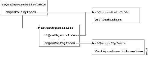
To access QoS configuration information and statistics for a particular QoS feature:
1. ![]() Look in cbQosServicePolicyTable and find the cbQosPolicyIndex assigned to the policy in which the feature is used.
Look in cbQosServicePolicyTable and find the cbQosPolicyIndex assigned to the policy in which the feature is used.
2. ![]() Use cbQosPolicyIndex to access the cbQosObjectsTable, and find the cbQosObjectsIndex and cbQosConfigIndex assigned to the QoS feature.
Use cbQosPolicyIndex to access the cbQosObjectsTable, and find the cbQosObjectsIndex and cbQosConfigIndex assigned to the QoS feature.
•![]() Use cbQosConfigIndex to access configuration tables (cbQosxxxCfgTable) for information about the feature.
Use cbQosConfigIndex to access configuration tables (cbQosxxxCfgTable) for information about the feature.
•![]() Use cbQosPolicyIndex and cbQosObjectsIndex to access QoS statistics tables (cbQosxxxStatsTable) for information about the QoS feature.
Use cbQosPolicyIndex and cbQosObjectsIndex to access QoS statistics tables (cbQosxxxStatsTable) for information about the QoS feature.
Sample QoS Configuration Settings
This section shows how QoS configuration settings are stored in CISCO-CLASS-BASED-QOS-MIB tables and shows information grouped by QoS object. However, the actual output of an SNMP query might show QoS information similar to the following. This is only a partial display of all QoS information.
7301# getmany -v3 10.86.0.94 test-user ciscoCBQosMIB
cbQosIfType.9583 = mainInterface(1)
cbQosIfType.9619 = mainInterface(1)
cbQosPolicyDirection.9583 = input(1)
cbQosPolicyDirection.9619 = output(2)
cbQosIfIndex.9583 = 3
cbQosIfIndex.9619 = 3
cbQosFrDLCI.9583 = 0
cbQosFrDLCI.9619 = 0
cbQosAtmVPI.9583 = 0
cbQosAtmVPI.9619 = 0
cbQosAtmVCI.9583 = 0
cbQosAtmVCI.9619 = 0
cbQosConfigIndex.9583.9583 = 9457
cbQosConfigIndex.9583.9585 = 9451
cbQosConfigIndex.9583.9587 = 9455
cbQosConfigIndex.9583.9589 = 9459
cbQosConfigIndex.9583.9591 = 9445
cbQosConfigIndex.9583.9593 = 9449
cbQosConfigIndex.9583.9595 = 9461
cbQosConfigIndex.9583.9597 = 1025
cbQosConfigIndex.9583.9599 = 1027
cbQosConfigIndex.9619.9619 = 9609
cbQosConfigIndex.9619.9621 = 9601
cbQosConfigIndex.9619.9623 = 9605
cbQosConfigIndex.9619.9625 = 9607
cbQosConfigIndex.9619.9627 = 9611
cbQosConfigIndex.9619.9629 = 1025
cbQosConfigIndex.9619.9631 = 1027
cbQosObjectsType.9583.9583 = policymap(1)
cbQosObjectsType.9583.9585 = classmap(2)
cbQosObjectsType.9583.9587 = matchStatement(3)
cbQosObjectsType.9583.9589 = police(7)
cbQosObjectsType.9583.9591 = classmap(2)
cbQosObjectsType.9583.9593 = matchStatement(3)
cbQosObjectsType.9583.9595 = police(7)
cbQosObjectsType.9583.9597 = classmap(2)
cbQosObjectsType.9583.9599 = matchStatement(3)
cbQosObjectsType.9619.9619 = policymap(1)
cbQosObjectsType.9619.9621 = classmap(2)
cbQosObjectsType.9619.9623 = matchStatement(3)
cbQosObjectsType.9619.9625 = matchStatement(3)
cbQosObjectsType.9619.9627 = queueing(4)
cbQosObjectsType.9619.9629 = classmap(2)
cbQosObjectsType.9619.9631 = matchStatement(3)
cbQosParentObjectsIndex.9583.9583 = 0
cbQosParentObjectsIndex.9583.9585 = 9583
cbQosParentObjectsIndex.9583.9587 = 9585
cbQosParentObjectsIndex.9583.9589 = 9585
cbQosParentObjectsIndex.9583.9591 = 9583
cbQosParentObjectsIndex.9583.9593 = 9591
cbQosParentObjectsIndex.9583.9595 = 9591
cbQosParentObjectsIndex.9583.9597 = 9583
cbQosParentObjectsIndex.9583.9599 = 9597
cbQosParentObjectsIndex.9619.9619 = 0
cbQosParentObjectsIndex.9619.9621 = 9619
cbQosParentObjectsIndex.9619.9623 = 9621
cbQosParentObjectsIndex.9619.9625 = 9621
cbQosParentObjectsIndex.9619.9627 = 9621
cbQosParentObjectsIndex.9619.9629 = 9619
cbQosParentObjectsIndex.9619.9631 = 9629
cbQosPolicyMapName.9457 = car
cbQosPolicyMapDesc.9457 =
cbQosCMName.1025 = class-default
cbQosCMDesc.1025 =
cbQosCMInfo.1025 = matchAny(3)
. . .
The following samples are QoS CLI show command outputs.
7301# show class-map
class-map match-any prec1_dscp16
match ip prec 1
match ip dscp 16
7301# show policy-map
policy-map cbwfq-wred
class prec1_dscp16
bandwidth percent 20
random-detect
random-detect exponential-weighting-constant 10
random-detect precedence 0 10 126 10
random-detect precedence 1 11 126 10
random-detect precedence 2 12 126 10
random-detect precedence 3 13 126 10
random-detect precedence 4 14 126 10
random-detect precedence 5 15 126 10
random-detect precedence 6 16 126 10
random-detect precedence 7 17 126 10
interface gi0/1
service-policy output cbwfq-wred
policy-map car
class prec1
          police 20000000 24000 24000 conform-action  set-dscp-transmit 5
exceed-action drop
class dscp16
police 20000000 24000 24000 conform-action transmit exceed-action transmit
interface pos4/0
service-policy input car
Note the following about the sample QoS configuration:
•![]() Policy maps that are not attached to an interface are not included with SNMP data or displayed by the show policy-map interface command. This is why pm-1Meg is shown but pm1 is not.
Policy maps that are not attached to an interface are not included with SNMP data or displayed by the show policy-map interface command. This is why pm-1Meg is shown but pm1 is not.
•![]() The default class map is always included with the SNMP data.
The default class map is always included with the SNMP data.
•![]() Class maps that have no action defined are not included with the SNMP data.
Class maps that have no action defined are not included with the SNMP data.
The following output is a sample of RED configuration information stored in MIB tables applied to a Cisco 7301 interface.
cbQosREDCfgExponWeight.9776 = 10
cbQosREDCfgMeanQsize.9776 = 0
cbQosREDCfgDscpPrec.9776 = precedence(1)
cbQosREDCfgMinThreshold.9776.0 = 10
cbQosREDCfgMinThreshold.9776.1 = 11
cbQosREDCfgMinThreshold.9776.2 = 12
cbQosREDCfgMinThreshold.9776.3 = 13
cbQosREDCfgMinThreshold.9776.4 = 14
cbQosREDCfgMinThreshold.9776.5 = 15
cbQosREDCfgMinThreshold.9776.6 = 16
cbQosREDCfgMinThreshold.9776.7 = 17
cbQosREDCfgMaxThreshold.9776.0 = 126
cbQosREDCfgMaxThreshold.9776.1 = 126
cbQosREDCfgMaxThreshold.9776.2 = 126
cbQosREDCfgMaxThreshold.9776.3 = 126
cbQosREDCfgMaxThreshold.9776.4 = 126
cbQosREDCfgMaxThreshold.9776.5 = 126
cbQosREDCfgMaxThreshold.9776.6 = 126
cbQosREDCfgMaxThreshold.9776.7 = 126
cbQosREDCfgPktDropProb.9776.0 = 10
cbQosREDCfgPktDropProb.9776.1 = 10
cbQosREDCfgPktDropProb.9776.2 = 10
cbQosREDCfgPktDropProb.9776.3 = 10
cbQosREDCfgPktDropProb.9776.4 = 10
cbQosREDCfgPktDropProb.9776.5 = 10
cbQosREDCfgPktDropProb.9776.6 = 10
cbQosREDCfgPktDropProb.9776.7 = 10
. . .
Monitoring QoS
This section provides information about how to monitor QoS on the router by checking the QoS statistics in the MIB tables described in Table A-2. For information about how to determine the amount of traffic to bill customers for, see the "Billing Customers for Traffic" section.
Note ![]() The CISCO-CLASS-BASED-QOS-MIB might contain more information than what is displayed in the output of CLI show commands.
The CISCO-CLASS-BASED-QOS-MIB might contain more information than what is displayed in the output of CLI show commands.
Considerations for Processing QoS Statistics
The router maintains 64-bit counters for most QoS statistics. However, some QoS counters are implemented as a 32-bit counter with a 1-bit overflow flag. In the following figures, these counters are shown as 33-bit counters.
When accessing QoS statistics in counters, consider the following:
•![]() SNMPv2c or SNMPv3 applications—Access the entire 64 bits of the QoS counter through cbQosxxx64 MIB objects.
SNMPv2c or SNMPv3 applications—Access the entire 64 bits of the QoS counter through cbQosxxx64 MIB objects.
•![]() SNMPv1 applications—Access QoS statistics in the MIB as follows:
SNMPv1 applications—Access QoS statistics in the MIB as follows:
–![]() Access the lower 32 bits of the counter through cbQosxxx MIB objects.
Access the lower 32 bits of the counter through cbQosxxx MIB objects.
–![]() Access the upper 32 bits of the counter through cbQosxxxOverflow MIB objects.
Access the upper 32 bits of the counter through cbQosxxxOverflow MIB objects.
Sample QoS Statistics
This section shows how QoS statistics are displayed in show commands and stored in CISCO-CLASS-BASED-QOS-MIB tables.
For ease-of-use, the display shows some counters as a single object even though the counter is implemented as three objects. For example, cbQosCMPrePolicyByte is implemented as:
cbQosCMPrePolicyByteOverflow
cbQosCMPrePolicyByte
cbQosCMPrePolicyByte64
Note ![]() Due to implementation features, some of the QoS statistics counters might wrap before they reach the maximum value they can accommodate.
Due to implementation features, some of the QoS statistics counters might wrap before they reach the maximum value they can accommodate.
The following is a sample of QoS class map statistics.
class-map dscp16
match ip dscp 16
class-map prec1
match ip prec 1
policy-map car
class prec1
police 20000000 24000 24000 conform-action set-dscp-transmit 5 exce
ed-action drop
class dscp16
police 20000000 24000 24000 conform-action transmit exceed-action transmit
interface atm3/0
pvc 1/99
service-policy input car
class-map prec2
match ip prec 2
class-map prec1
match ip prec 1
policy-map cbwfq
class prec1
bandwidth perc 40
queue-limit 33
class prec2
bandwidth perc 50
queue-limit 55
interface atm3/0
pvc 1/99
service-policy output cbwfq
cbQosPoliceStatsTable
cbQosPoliceStatsEntry
cbQosPoliceConformedPktOverflow.9535.9541 = 0
cbQosPoliceConformedPkt.9535.9541 = 226961
cbQosPoliceConformedPkt64.9535.9541 = 0x000037691
cbQosPoliceConformedByte.9535.9541 = 230592376
cbQosPoliceConformedByteOverflow.9535.9541 = 0
cbQosPoliceConformedByte64.9535.9541 = 0x00dbe8f78
cbQosPoliceConformedBitRate.9535.9541 = 0
cbQosPoliceExceededPktOverflow.9535.9541 = 0
cbQosPoliceExceededPkt64.9535.9541 = 0x000000000
cbQosPoliceExceededByte.9535.9541 = 0
cbQosPoliceExceededBitRate.9535.9541 = 0
cbQosPoliceViolatedPktOverflow.9535.9541 = 0
cbQosPoliceViolatedPkt.9535.9541 = 0
cbQosPoliceViolatedByteOverflow.9535.9541 = 0
cbQosPoliceViolatedByte.9535.9541 = 0
cbQosPoliceViolatedBitRate.9535.9541 = 0
cbQosQueueingStatsTable
cbQosQueueingStatsEntry
cbQosQueueingCurrentQDepth.9619.9627 = 0
cbQosQueueingMaxQDepth.9619.9627 = 0
cbQosQueueingDiscardByte.9619.9627 = 700700636
cbQosQueueingDiscardPkt.9619.9627 = 697909
Sample QoS Applications
This section presents examples of sample code showing how to retrieve information from the CISCO-CLASS-BASED-QOS-MIB to use for QoS billing operations. You can use these examples to help you develop billing applications. The sample code shows how to:
•![]() Checking Customer Interfaces for Service Policies
Checking Customer Interfaces for Service Policies
•![]() Retrieving QoS Billing Information
Retrieving QoS Billing Information
Checking Customer Interfaces for Service Policies
This section describes a sample algorithm that checks the CISCO-CLASS-BASED-QOS-MIB for customer interfaces with service policies, and marks those interfaces for further application processing (such as billing for QoS services).
The algorithm uses two SNMP get-next requests for each customer interface. For example, if the router has 2000 customer interfaces, 4000 SNMP get-next requests are required to determine whether those interfaces have transmit and receive service policies associated with them.
Note ![]() This algorithm is for informational purposes only. Your application needs may be different.
This algorithm is for informational purposes only. Your application needs may be different.
Check the MIB to see which interfaces are associated with a customer. Create a pair of flags to show whether a service policy has been associated with the transmit and receive directions of a customer interface. Mark non-customer interfaces TRUE (so no more processing is required for them).
FOR each ifEntry DO
IF (ifEntry represents a customer interface) THEN
servicePolicyAssociated[ifIndex].transmit = FALSE;
servicePolicyAssociated[ifIndex].receive = FALSE;
ELSE
servicePolicyAssociated[ifIndex].transmit = TRUE;
servicePolicyAssociated[ifIndex].receive = TRUE;
END-IF
END-FOR
Examine the cbQosServicePolicyTable and mark each customer interface that has a service policy attached to it. Also note the direction of the interface.
x = 0;
done = FALSE;
WHILE (!done)
status = snmp-getnext (
ifIndex = cbQosIfIndex.x,
direction = cbQosPolicyDirection.x
);
IF (status != `noError') THEN
done = TRUE
ELSE
x = extract cbQosPolicyIndex from response;
IF (direction == `output') THEN
servicePolicyAssociated[ifIndex].transmit = TRUE;
ELSE
servicePolicyAssociated[ifIndex].receive = TRUE;
END-IF
END-IF
END-WHILE
Manage cases in which a customer interface does not have a service policy attached to it.
FOR each ifEntry DO
IF (!servicePolicyAssociated[ifIndex].transmit) THEN
Perform processing for customer interface without a transmit service policy.
END-IF
IF (!servicePolicyAssociated[ifIndex].receive) THEN
Perform processing for customer interface without a receive service policy.
END-IF
END-FOR
Retrieving QoS Billing Information
This section describes a sample algorithm that uses the CISCO-CLASS-BASED-QOS-MIB for QoS billing operations. The algorithm periodically retrieves post-policy input and output statistics, combines them, and sends the result to a billing database.
The algorithm uses the following:
•![]() One SNMP get request per customer interface—to retrieve the ifAlias.
One SNMP get request per customer interface—to retrieve the ifAlias.
•![]() Two SNMP get-next requests per customer interface—to retrieve service policy indexes.
Two SNMP get-next requests per customer interface—to retrieve service policy indexes.
•![]() Two SNMP get-next requests per customer interface for each object in the policy—to retrieve post-policy bytes. For example, if there are 100 interfaces and 10 objects in the policy, the algorithm requires 2000 get-next requests (2 x 100 x 10).
Two SNMP get-next requests per customer interface for each object in the policy—to retrieve post-policy bytes. For example, if there are 100 interfaces and 10 objects in the policy, the algorithm requires 2000 get-next requests (2 x 100 x 10).
Note ![]() This algorithm is for informational purposes only. Your application needs may be different.
This algorithm is for informational purposes only. Your application needs may be different.
Set up customer billing information.
FOR each ifEntry DO
IF (ifEntry represents a customer interface) THEN
status = snmp-getnext (id = ifAlias.ifIndex);
IF (status != `noError') THEN
Perform error processing.
ELSE
billing[ifIndex].isCustomerInterface = TRUE;
billing[ifIndex].customerID = id;
billing[ifIndex].transmit = 0;
billing[ifIndex].receive = 0;
END-IF
ELSE
billing[ifIndex].isCustomerInterface = FALSE;
END-IF
END-FOR
Retrieve billing information.
x = 0;
done = FALSE;
WHILE (!done)
response = snmp-getnext (
ifIndex = cbQosIfIndex.x,
direction = cbQosPolicyDirection.x
);
IF (response.status != `noError') THEN
done = TRUE
ELSE
x = extract cbQosPolicyIndex from response;
IF (direction == `output') THEN
billing[ifIndex].transmit = GetPostPolicyBytes (x);
ELSE
billing[ifIndex].receive = GetPostPolicyBytes (x);
END-IF
END-IF
END-WHILE
Determine the number of post-policy bytes for billing purposes.
GetPostPolicyBytes (policy)
x = policy;
y = 0;
total = 0;
WHILE (x == policy)
response = snmp-getnext (type = cbQosObjectsType.x.y);
IF (response.status == `noError')
x = extract cbQosPolicyIndex from response;
y = extract cbQosObjectsIndex from response;
IF (x == policy AND type == `classmap')
status = snmp-get (bytes = cbQosCMPostPolicyByte64.x.y);
IF (status == `noError')
total += bytes;
END-IF
END-IF
END-IF
END-WHILE
RETURN total;
Billing Customers for Traffic
This section describes how to use SNMP QoS information to determine the amount of traffic to bill to your customers. It also includes a scenario for demonstrating that a QoS service policy attached to an interface is policing traffic on that interface.
This section describes the following topics:
•![]() Determining the Amount of Traffic to Bill to a Customer
Determining the Amount of Traffic to Bill to a Customer
•![]() Scenario for Demonstrating QoS Traffic Policing
Scenario for Demonstrating QoS Traffic Policing
Input and Output Interface Counts
The router maintains information about the number of packets and bytes that are received on an input interface and transmitted on an output interface. When a QoS service policy is attached to an interface, the router applies the rules of the policy to traffic on the interface and increments the packet and bytes counts on the interface.
The following CISCO-CLASS-BASED-QOS-MIB objects provide interface counts:
•![]() cbQosCMDropPkt and cbQosCMDropByte (cbQosCMStatsTable)—Total number of packets and bytes that were dropped because they exceeded the limits set by the service policy. These counts include only those packets and bytes that were dropped because they exceeded service policy limits. The counts do not include packets and bytes dropped for other reasons.
cbQosCMDropPkt and cbQosCMDropByte (cbQosCMStatsTable)—Total number of packets and bytes that were dropped because they exceeded the limits set by the service policy. These counts include only those packets and bytes that were dropped because they exceeded service policy limits. The counts do not include packets and bytes dropped for other reasons.
•![]() cbQosPoliceConformedPkt and cbQosPoliceConformedByte (cbQosPoliceStatsTable)—Total number of packets and bytes that conformed to the limits of the service policy and were transmitted.
cbQosPoliceConformedPkt and cbQosPoliceConformedByte (cbQosPoliceStatsTable)—Total number of packets and bytes that conformed to the limits of the service policy and were transmitted.
Determining the Amount of Traffic to Bill to a Customer
Perform these steps to determine how much traffic on an interface is billable to a particular customer:
Step 1 ![]() Determine which service policy on the interface applies to the customer.
Determine which service policy on the interface applies to the customer.
Step 2 ![]() Determine the index values of the service policy and class map used to define the customer's traffic. You will need this information in the following steps.
Determine the index values of the service policy and class map used to define the customer's traffic. You will need this information in the following steps.
Step 3 ![]() Access the cbQosPoliceConformedPkt object (cbQosPoliceStatsTable) for the customer to determine how much traffic on the interface is billable to this customer.
Access the cbQosPoliceConformedPkt object (cbQosPoliceStatsTable) for the customer to determine how much traffic on the interface is billable to this customer.
Step 4 ![]() (Optional) Access the cbQosCMDropPkt object (cbQosCMStatsTable) for the customer to determine how much of the customer's traffic was dropped because it exceeded service policy limits.
(Optional) Access the cbQosCMDropPkt object (cbQosCMStatsTable) for the customer to determine how much of the customer's traffic was dropped because it exceeded service policy limits.
Scenario for Demonstrating QoS Traffic Policing
This section describes a scenario that demonstrates the use of SNMP QoS statistics to determine how much traffic on an interface is billable to a particular customer. It also shows how packet counts are affected when a service policy is applied to traffic on the interface.
To create the scenario, follow these steps, each of which is described in the sections that follow:
1. ![]() Create and attach a service policy to an interface.
Create and attach a service policy to an interface.
2. ![]() View packet counts before the service policy is applied to traffic on the interface.
View packet counts before the service policy is applied to traffic on the interface.
3. ![]() Issue a ping command to generate traffic on the interface. Note that the service policy is applied to the traffic.
Issue a ping command to generate traffic on the interface. Note that the service policy is applied to the traffic.
4. ![]() View packet counts after the service policy has been applied to determine how much traffic to bill the customer for:
View packet counts after the service policy has been applied to determine how much traffic to bill the customer for:
•![]() Conformed packets—The number of packets within the range set by the service policy and for which you can charge the customer.
Conformed packets—The number of packets within the range set by the service policy and for which you can charge the customer.
•![]() Exceeded or dropped packets—The number of packets that were not transmitted because they were outside the range of the service policy. These packets are not billable to the customer.
Exceeded or dropped packets—The number of packets that were not transmitted because they were outside the range of the service policy. These packets are not billable to the customer.
Note ![]() In the above scenario, the Cisco 7301 router is used as an interim device (that is, traffic originates elsewhere and is destined for another device).
In the above scenario, the Cisco 7301 router is used as an interim device (that is, traffic originates elsewhere and is destined for another device).
Service Policy Configuration
This scenario uses the following policy-map configuration. For information on how to create a policy map, see "Configuring Quality of Service" in the Cisco 7301 Internet Series Router Software Configuration Guide.
policy-map police-out
class BGPclass
police 8000 1000 2000 conform-action transmit exceed-action drop
interface GigabitEthernet1/0/0.10
description VLAN voor klant
encapsulation dot1Q 10
ip address 10.0.0.17 255.255.255.248
service-policy output police-out
Packet Counts Before the Service Policy Is Applied
The following CLI and SNMP output shows the interface's output traffic before the service policy is applied:
Sample CLI Command Output
7301# show policy-map interface g6/0/0.10
GigabitEthernet6/0/0.10
Service-policy output: police-out
Class-map: BGPclass (match-all)
0 packets, 0 bytes
30 second offered rate 0 bps, drop rate 0 bps
Match: access-group 101
Police:
8000 bps, 1000 limit, 2000 extended limit
conformed 0 packets, 0 bytes; action: transmit
exceeded 0 packets, 0 bytes; action: drop
Class-map: class-default (match-any)
4 packets, 292 bytes
30 second offered rate 0 bps, drop rate 0 bps
Match: any
Output queue: 0/8192; 2/128 packets/bytes output, 0 drops
Sample SNMP Output
7301# getone -v2c 10.86.0.63 public ifDescr.65
ifDescr.65 = GigabitEthernet6/0/0.10-802.1Q vLAN subif
Generating Traffic
The following set of ping commands generates traffic:
7301# ping
Protocol [ip]:
Target IP address: 10.0.0.18
Repeat count [5]: 99
Datagram size [100]: 1400
Timeout in seconds [2]: 1
Extended commands [n]:
Sweep range of sizes [n]:
Type escape sequence to abort.
Sending 100, 1400-byte ICMP Echos to 10.0.0.18, timeout is 1 seconds:
.!!.!..!.!..!.!.!..!.!..!.!..!.!.!..!.!..!.!..!.!.!..!.!..!.!..!.!.!..
!.!..!.!..!.!.!..!.!..!.!..!.!
Success rate is 42 percent (42/100), round-trip min/avg/max = 1/1/1 ms
Packet Counts After the Service Policy Is Applied
After you generate traffic using the ping command, look at the number of packets that exceeded and conformed to the committed access rate (CAR) set by the police command:
•![]() 42 packets conformed to the police rate and were transmitted
42 packets conformed to the police rate and were transmitted
•![]() 57 packets exceeded the police rate and were dropped
57 packets exceeded the police rate and were dropped
The following CLI and SNMP output show the counts on the interface after the service policy is applied. (In the output, conformed and exceeded packet counts are shown in boldface.)
CLI Command Output
7301# show policy-map interface g6/0/0.10
FastEthernet6/0/0.10
Service-policy output: police-out
Class-map: BGPclass (match-all)
198 packets, 281556 bytes
30 second offered rate 31000 bps, drop rate 11000 bps
Match: access-group 101
Police:
8000 bps, 1000 limit, 2000 extended limit
conformed 42 packets, 59892 bytes; action: transmit
exceeded 57 packets, 81282 bytes; action: drop
Class-map: class-default (match-any)
15 packets, 1086 bytes
30 second offered rate 0 bps, drop rate 0 bps
Match: any
Output queue: 0/8192; 48/59940 packets/bytes output, 0 drops
SNMP Output
7301# getmany -v2c 10.86.0.63 public ciscoCBQosMIB
. . .
cbQosCMDropPkt.1143.1145 = 57
. . .
cbQosPoliceConformedPkt.1143.1151 = 42
. . .
Using CISCO-AAA-SESSION-MIB
The following object support was added to the CISCO-AAA-SESSION-MIB to improve interface mapping sessions:
•![]() casnNasPort—Identifies a particular conceptual row associated with the session identified by casnSessionId. The conceptual row that this object points to represents a port that is used to transport a session. If the port transporting the session cannot be determined, the value of this object will be zeroDotZero
casnNasPort—Identifies a particular conceptual row associated with the session identified by casnSessionId. The conceptual row that this object points to represents a port that is used to transport a session. If the port transporting the session cannot be determined, the value of this object will be zeroDotZero
For example, a session is established using an ATM PVC. If the ifIndex of the ATM interface is 7 and the VPI/VCI values of the PVC are 1, 100 respectively, then the value of this object is (in this example):
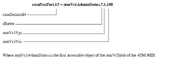
•![]() casnVaiIfIndex—Identifies the ifIndex of the Virtual Access Interface (VAI) that is associated with the PPP session. This interface may not be represented in the IF-MIB in which case the value of this object will be zero.
casnVaiIfIndex—Identifies the ifIndex of the Virtual Access Interface (VAI) that is associated with the PPP session. This interface may not be represented in the IF-MIB in which case the value of this object will be zero.
 Feedback