System Setup and Software Installation Guide for Cisco Optical Site Manager, IOS XR
Bias-Free Language
The documentation set for this product strives to use bias-free language. For the purposes of this documentation set, bias-free is defined as language that does not imply discrimination based on age, disability, gender, racial identity, ethnic identity, sexual orientation, socioeconomic status, and intersectionality. Exceptions may be present in the documentation due to language that is hardcoded in the user interfaces of the product software, language used based on RFP documentation, or language that is used by a referenced third-party product. Learn more about how Cisco is using Inclusive Language.
This chapter outlines the configuration tasks for Cisco Optical Site Manager, covering both standalone and high availability
modes.
Configure Cisco Optical Site Manager in standalone mode for NCS 1010 or NCS 1014
Cisco Optical Site Manager can be configured in standalone mode on a single NCS 1010 or NCS 1014 controller card. This mode
is useful for deployments where local management via a GUI is needed, or where interaction with third-party controllers is
required without full network-wide SDN automation.
The configuration involves setting up Cisco Optical Site Manager interfaces, defining management interface parameters, and
establishing user credentials for access.
Before you begin
Verify that these configurations are enabled before configuring Cisco Optical Site Manager in standalone mode on NCS 1010
or NCS 1014:
Commit the changes and exit the configuration modes using the commit and end commands.
Example:
RP/0/RP0/CPU0:ios(config-cosm)# commit
RP/0/RP0/CPU0:ios(config-cosm)# end
Step 6
Verify the Cisco Optical Site Manager status using the show cosm status command.
Example:
P/0/RP0/CPU0:ios#show cosm status
Fri Nov 14 10:26:44.215 UTC
COSM state: CLIENT_REGISTERED
AppMgr app state: UNKNOWN
AppMgr container state: UNKNOWN
Container status: Not present
Last error: 'Appmgr' detected the 'warning' condition 'Application not found'
Role: UNKNOWN
You can also use the show running-config cosm command to verify the configured parameters, though user credentials are not displayed.
Cisco Optical Site Manager is configured in the standalone mode.
Cisco Optical Site Manager High Availability (HA) provides continuous management and operational resilience for Cisco optical
devices. By deploying two instances, one as Active and the other as Standby, HA ensures that device management remains uninterrupted
even if one instance fails.
How does Cisco Optical Site Manager high availability ensure operational continuity?
Cisco Optical Site Manager High Availability (HA) provides a robust solution for managing device operations by utilizing dual
application instances and specialized network interfaces.
The main features of Cisco Optical Site Manager high availability include:
Two devices must be able to communicate with each other, allowing their respective Cisco Optical Site Manager instances to
coordinate application roles (active or standby) and manage operations.
Each device requires a Cisco Optical Site Manager management interface configured with the same IP address, starting in a
shutdown state. This interface automatically transitions between UP and DOWN states based on whether the device is active
or standby.
A dedicated Cisco Optical Site Manager redundancy interface is used to establish the high availability communication channel
and typically serves as the device’s management interface.
When in the active role, Cisco Optical Site Manager binds the HA server to the redundancy interface’s IP address on port 5454.
When in the Standby role, Cisco Optical Site Manager connects to the peer’s redundancy interface IP address on port 5454 to
communicate with the active instance.
HA roles and interfaces
Active role: manages all device operations and binds the HA server to its redundancy interface and port.
Standby role: monitors the active instance and connects to the peer’s redundancy IP and port. It is ready to take over if needed.
Redundancy interface: network interface used solely for HA communication between Cisco Optical Site Manager instances.
Management interface: interface with the same IP address on both devices, managed automatically depending on the instance role.
Note
High availability is not supported on NCS 1004 and NCS 1001.
Configure Cisco Optical Site Manager in high availability on NCS 1000
Configure High Availability (HA) on Cisco Optical Site Manager is to enable fast recovery from faults in the optical transport
network and to maintain service continuity by switching to standby components when active ones fail.
Cisco Optical Site Manager HA configuration requires these interfaces configured.
cosm mgmt-interface-name: This interface must be configured with same IP address on both Cisco Optical Site Manager active and standby devices. This
interface must be configured in a shutdown state and will automatically transition between UP and DOWN states based on the
role (Active or Stand-By) assigned by the application.
cosm redundancy interface-name: This interface must be configured with the redundancy interface and is used to establish the high availability communication
channel and is typically the interface used for device management.
redundancy gateway-ip: Specifies the gateway IP address (for example, 10.0.2.1) used by Cisco Optical Site Manager to reach peer devices or for routing HA traffic in environments where a direct path to
the peer is not available.
For releases 24.x.x and 25.x.x, verify that the redundancy interface-name IP address and the redundancy peer-ip address are not substrings of each other. For example, configuring 10.0.1.1 as the redundancy interface-name and 10.0.1.10 or 10.0.1.101 as the redundancy peer-ip (or vice-versa) causes Cisco Optical Site Manager HA to fail during startup.
Step 4
Configure the HA interface name.
This is the interface of the device running the Cisco Optical Site Manager HA instance, which is used for all HA traffic.
Commit the changes and exit all configuration modes.
Example:
RP/0/RP0/CPU0:ios(config-cosm)# commit
RP/0/RP0/CPU0:ios(config-cosm)# end
Step 6
Perform these steps 1 to 6 on both the second Cisco Optical Site Manager host device.
Step 7
Verify the HA configuration on both host devices.
Example:
RP/0/RP0/CPU0:ios#show cosm status
Fri Nov 14 10:26:44.215 UTC
COSM state: CLIENT_REGISTERED
AppMgr app state: UNKNOWN
AppMgr container state: UNKNOWN
Container status: Not present
Last error: 'Appmgr' detected the 'warning' condition 'Application not found'
Role: UNKNOWN
You can view the active and standby application status in the Device Software section of the Software Manager menu.
Note
If the HA node is on loopback, the MAC address of the HA device is displayed as N/A in the Devices section of the Device Configuration page.
This example explains how to configure Cisco Optical Site Manager HA on a NCS 1010 or NCS 1014 device.
RP/0/RP0/CPU0:ios#configure terminal
RP/0/RSP0/CPU0:ios(config)# cosm
RP/0/RP0/CPU0:ios(config-cosm)# redundancy gateway-ip 10.0.2.1
RP/0/RP0/CPU0:ios(config-cosm)# redundancy peer-ip 10.0.1.12
RP/0/RP0/CPU0:ios(config-cosm)# redundancy interface-name MgmtEth 0/RP0/CPU0/2
RP/0/RP0/CPU0:ios(config-cosm)# commit
RP/0/RP0/CPU0:ios(config-cosm)# end
RP/0/RP0/CPU0:ios#show cosm status
Fri Nov 14 10:26:44.215 UTC
COSM state: CLIENT_REGISTERED
AppMgr app state: UNKNOWN
AppMgr container state: UNKNOWN
Container status: Not present
Last error: 'Appmgr' detected the 'warning' condition 'Application not found'
Role: UNKNOWN
These commands are used to configure HA in Cisco Optical Site Manager on a NCS 1000 device.
Command
Description
configure
Enters global configuration mode.
cosm user-name <username>
Configures Cisco Optical Site Manager application username.
cosm user-password <password>
Configures Cisco Optical Site Manager application password.
cosm mgmt-interface-name <type> <number>
Configures the Cisco Optical Site Manager management interface. All Cisco Optical Site Manager NBI services (web UI, NETCONF,
RESTCONF) are available on this interface.
cosm redundancy interface-name <type> <number>
Configures Cisco Optical Site Manager high availability interface. The interface is used to communicate with the peer device.
cosm redundancy peer-ip <IP-address>
Configures the IP address of the peer device, where other Cisco Optical Site Manager is running.
cosm redundancy gateway-ip <IP-address>
Configures the IP address of a target device that is always reachable by both devices hosting Cisco Optical Site Manager in
high availability. Configuring the same gateway IP on both devices is strongly recommended.
Cisco Optical Site Manager uses this target device to perform checks in certain high availability scenarios. The target device
must be different from the cosm redundancy peer-ip. The target device may be the subnet gateway, the multilayer switch connecting the two devices, or another suitable device.
commit
Commits the changes.
end
Exits the global configuration mode.
Deployment models for HA in Cisco Optical Site Manager
Cisco Optical Site Manager supports several deployment models for implementing high availability (HA), each with distinct
configuration requirements, advantages, and dependencies on the Data Communication Network (DCN) architecture and local site
availability. Each model:
analyzes possible deployment scenarios, detailing device connections and configurations,
covers routing protocols in use and information on any additional devices involved.
Cisco Optical Site Manager supports these deployment models:
Dual-homing deployment with devices connected to DCN: This model involves connecting devices to the DCN using a dual-homing setup.
Single-homing deployment with devices connected to DCN: This model utilizes a single-home connection for devices to the DCN.
Deployment with devices interconnected and managed remotely: In this model, devices are interconnected and managed remotely through the Optical Service Channel (OSC).
Deployment with devices interconnected with redundancy and managed remotely: This model extends the previous one by incorporating redundancy for devices interconnected and remotely managed via OSC.
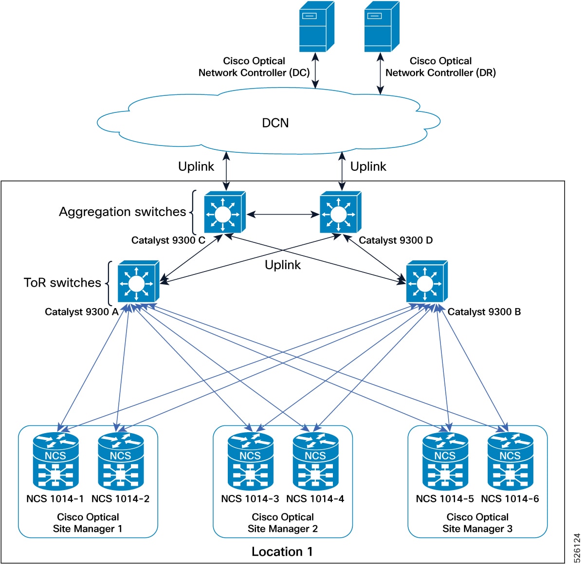
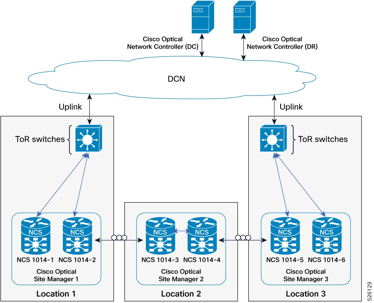
Dual-homing deployment with devices connected to DCN
This deployment model ensures that Cisco Optical Site Manager can always communicate with its peer, routing traffic through
an alternative interface, cable, or switch if one fails.
Requirements for the dual-homing deployment
This HA deployment model requires following conditions:
Both Cisco Optical Site Manager redundancy and management interfaces must be configured as Loopback interfaces.
The IP addresses assigned to the MgmtEth interfaces of the devices are typically part of a private subnet, isolated under
the Top-of-Rack (ToR) switches.
Loopback IP addresses are distributed within the Data Communication Network (DCN) and must be reachable from Cisco Optical
Network Controller.
Loopback 0 interfaces are designated as Cisco Optical Site Manager management interfaces.
Loopback 1 interfaces serve as Cisco Optical Site Manager redundancy interfaces, also providing direct access to the devices.
Implementing this deployment model requires specific network configurations and routing considerations:
ToR switches must advertise the default route to downstream devices. This can be achieved by configuring a static route on
the devices or by using `default-information originate` with OSPF on the switches.
The two devices hosting Cisco Optical Site Manager in high availability must have a static route or routing protocol configuration
to reach the peer's Cisco Optical Site Manager redundancy interface (for example, Loopback 1 interface) using the VRRP IP
as the next hop.
ToR switches should implement VRRP and channel aggregation on multiple ports towards the peer switch for enhanced redundancy.
This figure explains the connections diagram of two-degrees node deployment model with devices connected to DCN in dual-homing.
Figure 1. Conceptual Explanation of High Availability Deployment for Devices Connected to DCN in a Dual-Homing Model
IP addressing schema for devices connected to DCN in dual-homing
This table details the IP addressing for the devices connected to DCN in dual-homing deployment model, with MgmtEth interfaces
of the devices using the 192.168.1.0/24 subnet and loopback interfaces distributed within the DCN as part of the 10.1.1.0/27
subnet.
Table 1. IP addressing schema for dual-homing deployment
Cisco Optical Site Manager instance
NCS device
NCS device interface
NCS device IP/Mask
Connected to switch
Connected to switch interface
Cisco Optical Site Manager 1
NCS 1000-1
MgmtEth0/RP0/CPU0/0
192.168.1.11/24
Catalyst 9300 (A)
Gil/0/1
MgmtEth0/RP0/CPU0/1
192.168.1.12/24
Catalyst 9300 (B)
Gil/0/1
Loopback 0
10.1.1.1/32
–
–
Loopback 1
10.1.1.11/32
–
–
NCS 1000-2
MgmtEth0/RP0/CPU0/0
192.168.1.13/24
Catalyst 9300 (A)
Gil/0/2
MgmtEth0/RP0/CPU0/1
192.168.1.14/24
Catalyst 9300 (B)
Gil/0/2
Loopback 0
10.1.1.1/32
–
–
Loopback 1
10.1.1.12/32
–
–
Cisco Optical Site Manager 2
NCS 1000-3
MgmtEth0/RP0/CPU0/0
192.168.1.15/24
Catalyst 9300 (A)
Gil/0/3
MgmtEth0/RP0/CPU0/1
192.168.1.16/24
Catalyst 9300 (B)
Gil/0/3
Loopback 0
10.1.1.2/32
–
–
Loopback 1
10.1.1.13/32
–
–
NCS 1000-4
MgmtEth0/RP0/CPU0/0
192.168.1.17/24
Catalyst 9300 (A)
Gil/0/4
MgmtEth0/RP0/CPU0/1
192.168.1.18/24
Catalyst 9300 (B)
Gil/0/4
Loopback 0
10.1.1.2/32
–
–
Loopback 1
10.1.1.14/32
–
–
Cisco Optical Site Manager 3
NCS 1000-5
MgmtEth0/RP0/CPU0/0
192.168.1.19/24
Catalyst 9300 (A)
Gil/0/5
MgmtEth0/RP0/CPU0/1
192.168.1.20/24
Catalyst 9300 (B)
Gil/0/5
Loopback 0
10.1.1.3/32
–
–
Loopback 1
10.1.1.15/32
–
–
NCS 1000-6
MgmtEth0/RP0/CPU0/0
192.168.1.21/24
Catalyst 9300 (A)
Gil/0/6
MgmtEth0/RP0/CPU0/1
192.168.1.22/24
Catalyst 9300 (B)
Gil/0/6
Loopback 0
10.1.1.3/32
–
–
Loopback 1
10.1.1.16/32
–
–
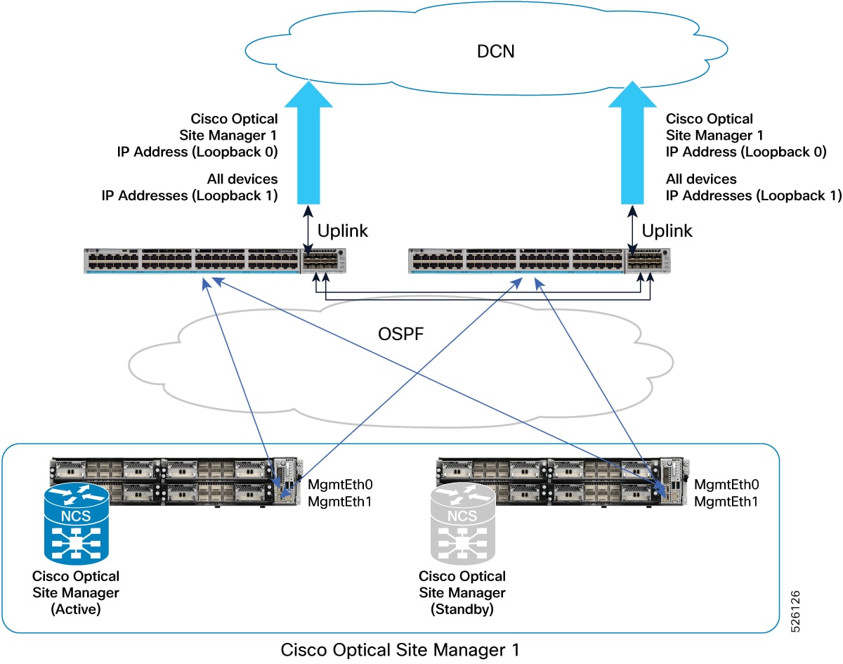
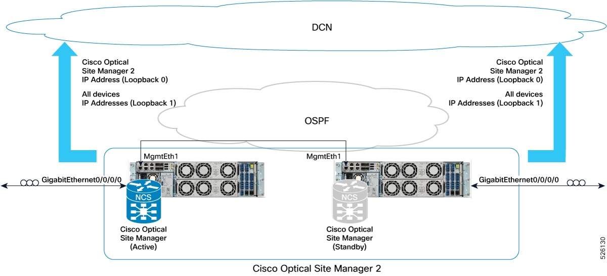
Practical example of devices connected to DCN in dual-homing
This figure provides a practical example of this deployment model, implemented with two Catalyst 9300 switches and two NCS1014
devices.
Figure 2. Deployment model featuring Catalyst 9300 Switches and Active/Standby NCS1014 devices
This example details the configurations for a Dual-Homing HA deployment model of NCS1014 devices connected to a DCN via Catalyst
9300 switches.
Catalyst 9300-A configuration
hostname CAT9300-A

fhrp version vrrp v3
ip routing

interface Vlan1
 ip address 192.168.1.253 255.255.255.0
 ip ospf 1 area 0
 vrrp 1 address-family ipv4
  address 192.168.1.1 primary
  exit-vrrp

interface TenGigabitEthernet1/1/1
 no switchport
 ip address <Uplink IP> <Uplink mask>

interface TenGigabitEthernet1/1/2
 channel-group 1 mode active

interface TenGigabitEthernet1/1/3
 channel-group 1 mode active

router ospf 1
 router-id 192.168.1.253
 default-information originate

ip route 0.0.0.0 0.0.0.0 <Uplink gateway IP>
Catalyst 9300-B configuration
hostname CAT9300-B

fhrp version vrrp v3
ip routing

interface Vlan1
 ip address 192.168.1.254 255.255.255.0
 ip ospf 1 area 0
 vrrp 1 address-family ipv4
  address 192.168.1.1 primary
  exit-vrrp

interface TenGigabitEthernet1/1/1
 no switchport
 ip address <Uplink IP> <Uplink mask>

interface TenGigabitEthernet1/1/2
 channel-group 1 mode active

interface TenGigabitEthernet1/1/3
 channel-group 1 mode active

router ospf 1
 router-id 192.168.1.254
 default-information originate

ip route 0.0.0.0 0.0.0.0 <Uplink gateway IP>
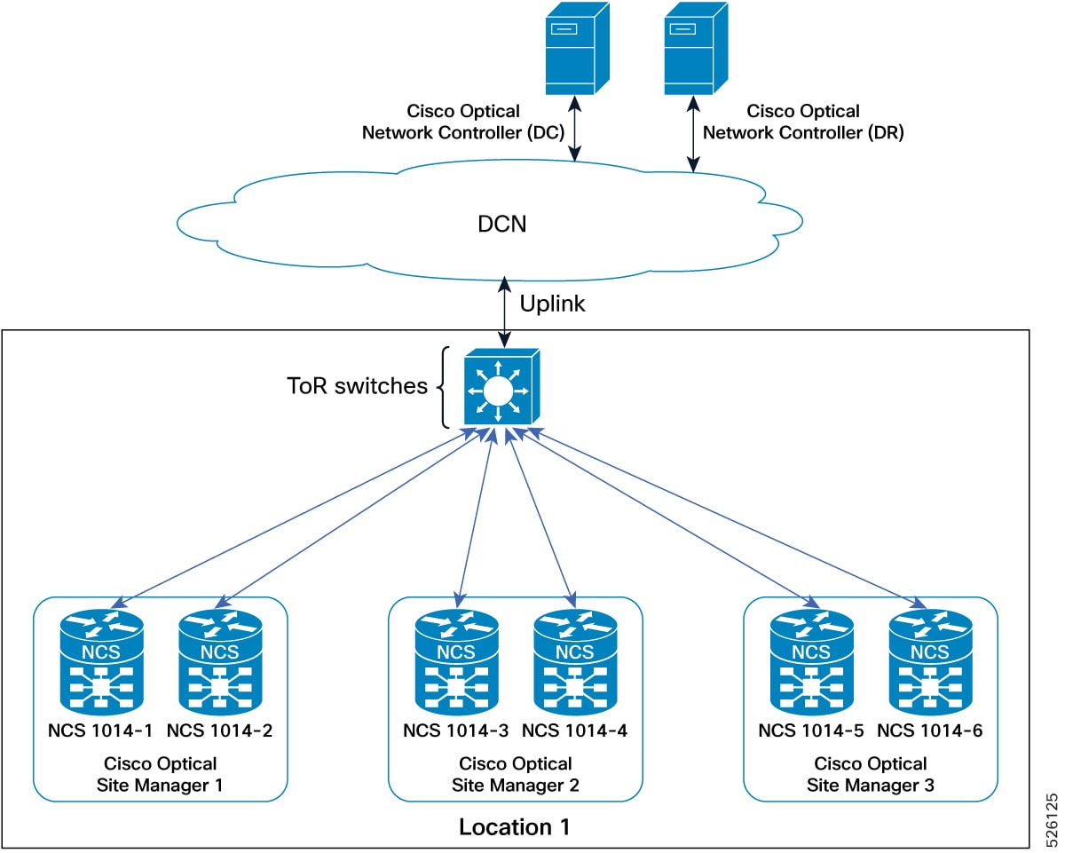
Single-homing deployment with devices connected to DCN
This deployment model for utilizes a single Top-of-Rack (ToR) switch and a single Management Ethernet interface for device
connectivity.
Requirements for the single-homing deployment
This HA deployment model requires following conditions:
Devices connect to the network over a single MgmtEth interface with a single cable to a single ToR switch.
The Cisco Optical Site Manager redundancy interface can match the cabled interface (MgmtEth 0).
The Cisco Optical Site Manager management interface must be configured as a Loopback interface (Loopback 0).
IP addresses assigned to the MgmtEth interfaces can be part of a private subnet isolated under the ToR switches.
The Loopback IP address should be distributed within the Data Communication Network (DCN) and be reachable from CONC.
Direct access to the devices is always possible through the MgmtEth 0 IP addresses.
This deployment model offers specific operational characteristics and configuration guidelines:
While a single failure can impact the reachability of a device, Cisco Optical Site Manager configured in high availability
remains continuously reachable.
The address plan and configurations described are specifically focused on the deployment of transponder platforms (e.g., NCS1014)
to highlight differences from other deployment models.
For optical line system platforms (e.g., NCS1010) in a mesh network, where an alternative path to reach the Cisco Optical
Site Manager peer device exists via OSC, the address plan and configurations are consistent with models using Loopback interfaces
for both Cisco Optical Site Manager redundancy and management interfaces (excluding MgmtEth0/RP0/CPU0/1 configuration if not
cabled).
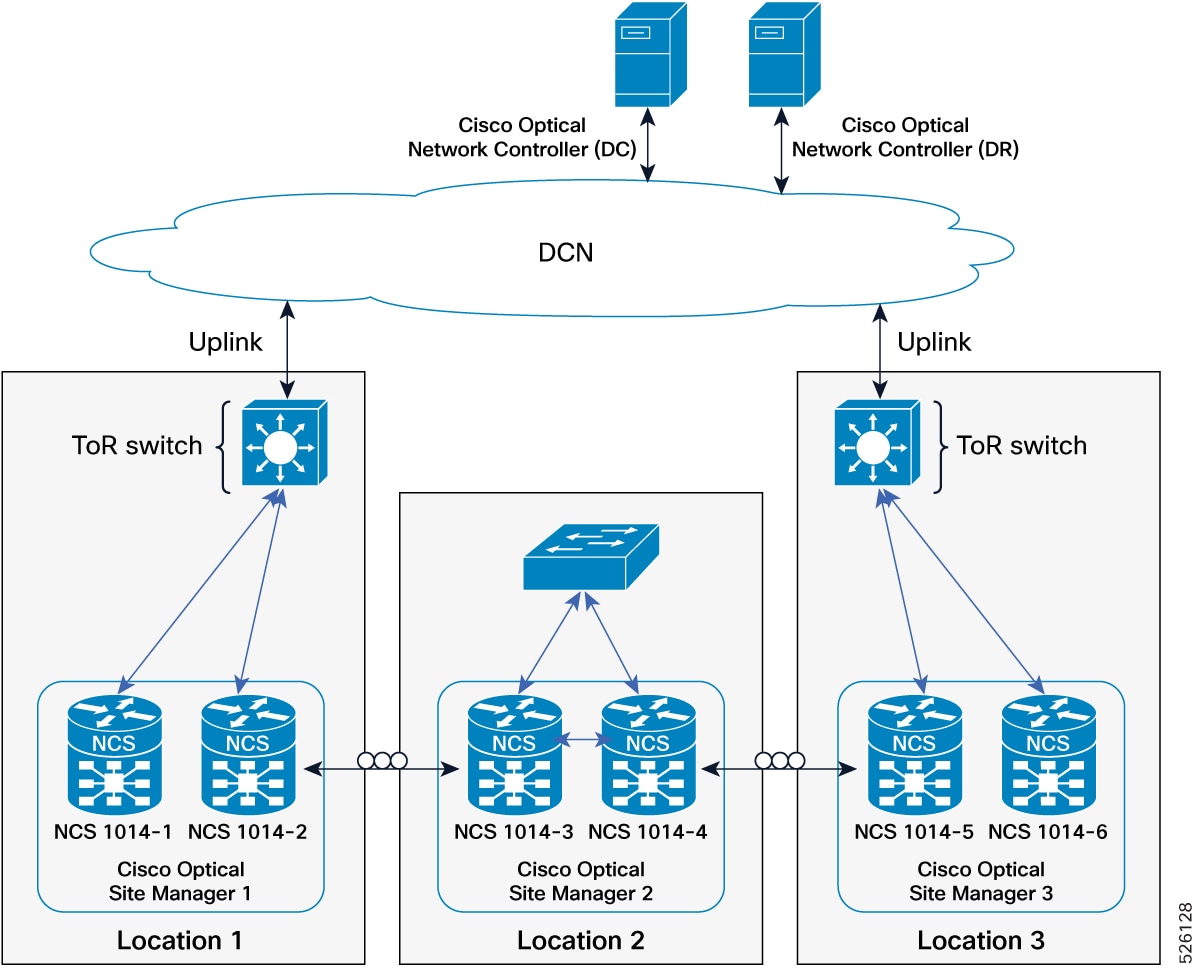
This figure explains the connections diagram of three Cisco Optical Site Manager instances configured in high availability
mode on NCS 1000 device with devices connected to DCN in single-homing.
Figure 3. Conceptual explanation of HA deployment for devices connected to DCN in a single-homing model
IP addressing schema for devices connected to DCN in single-homing
This table details the IP addressing for the devices connected to DCN in single-homing deployment model, with the MgmtEth interface of the devices in subnet 192.168.1.0/24 and the Loopback interface distributed in the DCN as part of the subnet 10.1.1.0/27.
Table 2. IP addressing schema for single-homing deployment
Cisco Optical Site Manager instance
NCS device
NCS device interface
NCS device IP/Mask
Connected to switch
Connected to switch interface
Cisco Optical Site Manager-1
NCS 1000-1
MgmtEth0/RP0/CPU0/0
192.168.1.11/24
Catalyst 9300
Gi1/0/1
Loopback 0
10.1.1.1/32
–
–
NCS 1000-2
MgmtEth0/RP0/CPU0/0
192.168.1.12/24
Catalyst 9300
Gi1/0/2
Loopback 0
10.1.1.1/32
–
–
Cisco Optical Site Manager-2
NCS 1000-3
MgmtEth0/RP0/CPU0/0
192.168.1.13/24
Catalyst 9300
Gi1/0/3
Loopback 0
10.1.1.2/32
–
–
NCS 1000-4
MgmtEth0/RP0/CPU0/0
192.168.1.14/24
Catalyst 9300
Gi1/0/4
Loopback 0
10.1.1.2/32
–
–
Cisco Optical Site Manager-3
NCS 1000-5
MgmtEth0/RP0/CPU0/0
192.168.1.15/24
Catalyst 9300
Gi1/0/5
Loopback 0
10.1.1.3/32
–
–
NCS 1000-6
MgmtEth0/RP0/CPU0/0
192.168.1.16/24
Catalyst 9300
Gi1/0/6
Loopback 0
10.1.1.3/32
–
–
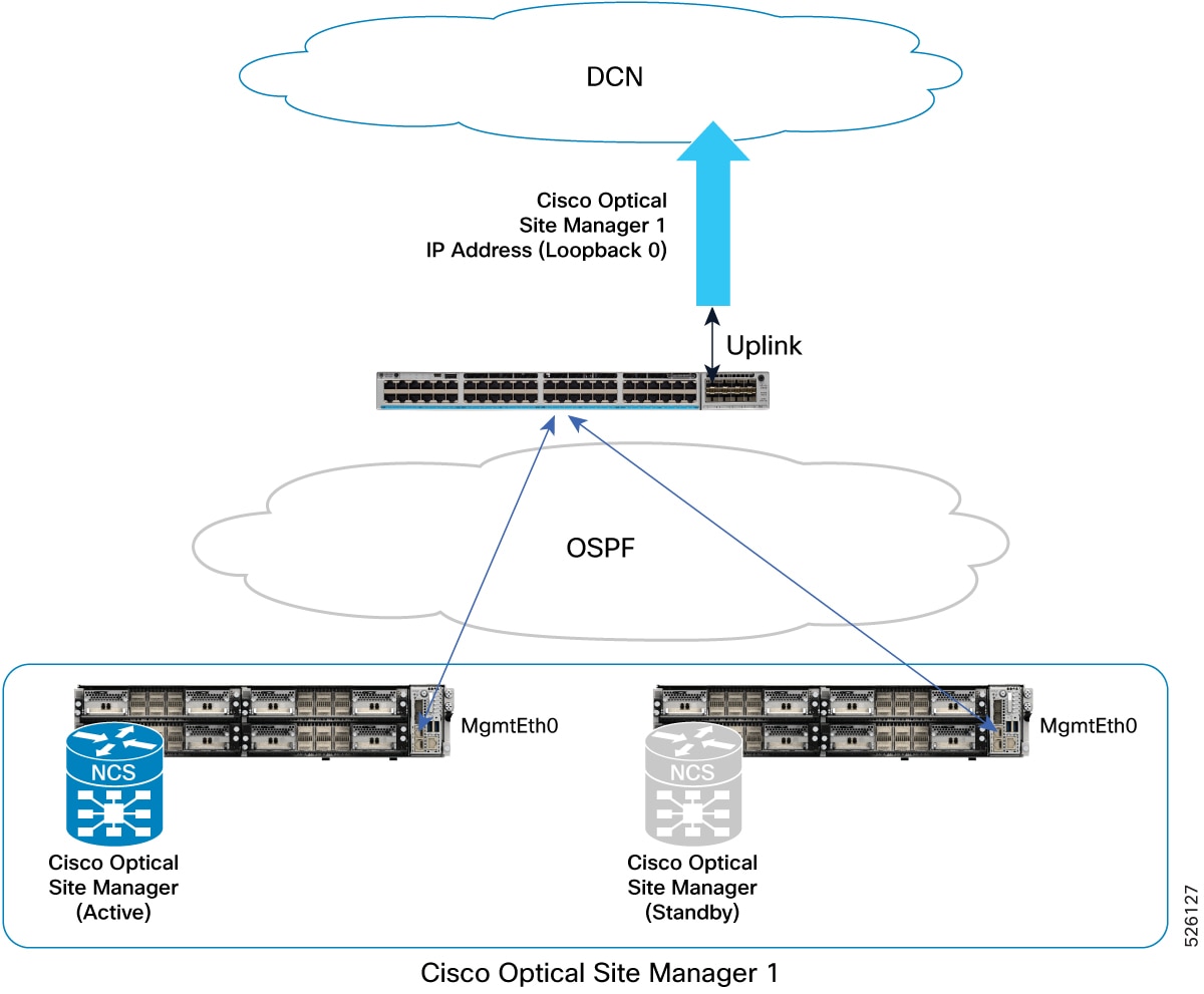
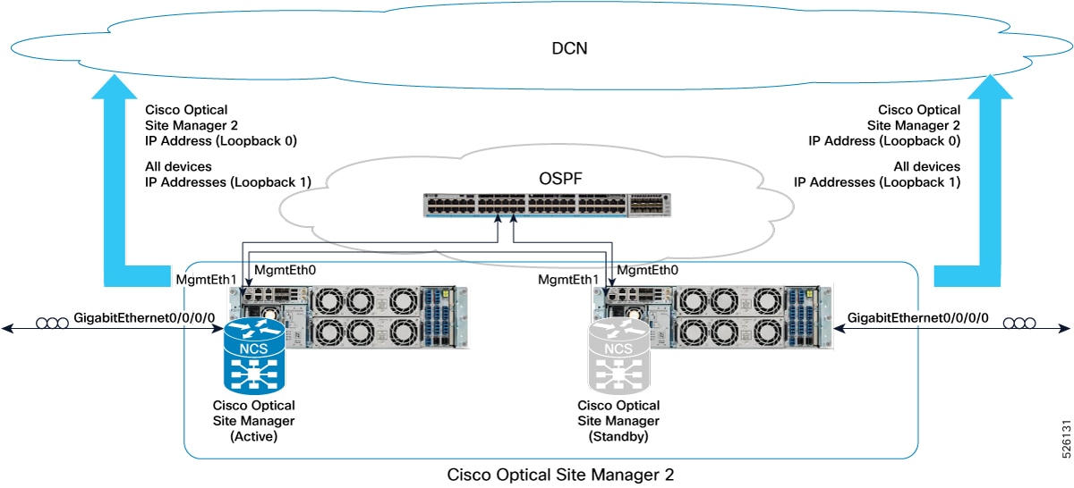
Practical example of devices connected to DCN in single-homing
This figure provides a practical example of this deployment model, implemented with one Catalyst 9300 switch and two NCS 1014
devices.
Figure 4. Deployment model featuring Catalyst 9300 switch and Active/Standby NCS 1014 devices
This example details the configurations for a single-homing HA deployment model of NCS 1014 devices connected to a DCN via
a Catalyst 9300 switch.
Catalyst 9300 configuration
hostname CAT9300

ip routing
interface Vlan1
 ip address 192.168.1.1 255.255.255.0
 ip ospf 1 area 0

interface TenGigabitEthernet1/1/1
 no switchport
 ip address <Uplink IP> <Uplink mask>

router ospf 1
 router-id 192.168.1.1
 default-information originate

ip route 0.0.0.0 0.0.0.0 <Uplink gateway IP>
Deployment with devices interconnected and managed remotely via OSC
This deployment model facilitates the management of a remote node, specifically a 2-degrees ROADM, where devices are interconnected
without direct Data Communication Network (DCN) connectivity.
Requirements for devices interconnected and managed remotely via OSC
This HA deployment model requires these conditions:
Cisco Optical Site Manager is configured in high availability mode on the remote node.
The remote node is reachable over the Optical Service Channel (OSC) from other nodes connected to the customer's DCN.
Devices within the remote node (e.g., Location 2) achieve DCN reachability through multiple paths over the OSC of different
degrees.
The two devices hosting Cisco Optical Site Manager in high availability are directly interconnected through an Ethernet cable
connected to their MgmtEth interfaces.
Implementing this deployment model requires specific interface configurations and routing to ensure high availability and
remote manageability, independent of failures.
Both Cisco Optical Site Manager redundancy and management interfaces must be configured as Loopback interfaces to ensure reachability
independent of potential failures.
IP addresses assigned to the MgmtEth interfaces (used for device interconnection) and GigabitEthernet interfaces must be strategically
distributed within the network to support interconnection failures.
Loopback IP addresses must be distributed within the DCN and be reachable from the Centralized Operations and Network Control
(CONC) system.
The two devices hosting Cisco Optical Site Manager in high availability in the remote location, which are directly interconnected
via an Ethernet cable on their MgmtEth interfaces, require a static route or routing protocol configuration.
This routing configuration must define how to reach the peer's Cisco Optical Site Manager redundancy interface (e.g., Loopback
1 interface) using the peer's MgmtEth interface as the next hop.
This figure shows a network diagram with three Cisco Optical Site Manager instances in three different locations, configured
in HA mode on NCS 1000 family devices. The Cisco Optical Site Manager-2 device in the middle is managed as a remote device.
Figure 5. Conceptual explanation of HA deployment for devices interconnected and managed remotely via OSC
IP addressing schema for devices interconnected and managed remotely via OSC
This table details the IP addressing for devices in the managed remotely via OSC deployment model. The MgmtEth interfaces are in subnet 192.168.1.12/31, and the Loopback interfaces are distributed in the DCN as part of subnet 10.1.1.0/27.
Table 3. IP addressing schema for deployment with devices interconnected and managed remotely
Cisco Optical Site Manager instance
NCS device
NCS device interface
NCS device IP/Mask
Connected to NCS device
Connected to NCS device interface
Cisco Optical Site Manager 2
NCS 1010-3
MgmtEth0/RP0/CPU0/1
192.168.1.12/31
Peer NCS 1010
MgmtEth0/RP0/CPU0/1
GigabitEthernet0/0/0/0
172.18.0.1/31
Neighbor
GigabitEthernet0/0/0/0
Loopback 0
10.1.1.2/32
–
–
Loopback 1
10.1.1.13/32
–
–
NCS 1010-4
MgmtEth0/RP0/CPU0/1
192.168.1.13/31
Peer NCS 1010
MgmtEth0/RP0/CPU0/1
GigabitEthernet0/0/0/0
172.18.0.2/31
Neighbor
GigabitEthernet0/0/0/0
Loopback 0
10.1.1.2/32
–
–
Loopback 1
10.1.1.14/32
–
–
Practical example of deployment with devices interconnected managed remotely via OSC
This figure provides a practical example of this deployment model, implemented with two NCS 1010 devices.
Figure 6. Example of deployment model with two NCS 1010 and Catalyst 93000 configured as 2-degrees ROADM
This example describes the configuration of two NCS 1010 devices deployed as a 2-degree ROADM, interconnected and managed
remotely through the OSC.
Deployment with devices interconnected with redundancy and managed remotely via OSC
This deployment model describes the management of a remote node, a 2-degrees ROADM, with physical redundancy, where Cisco
Optical Site Manager is configured in high availability and reachable over the Optical Service Channel.
Requirements for devices interconnected with redundancy and managed remotely via OSC
This HA deployment model requires these conditions:
Devices in the remote node are interconnected with physical redundancy and lack direct DCN connectivity.
Cisco Optical Site Manager instances are configured in high availability, accessible via OSC from other nodes connected to
the customer's DCN.
Devices within the remote node (Location 2) achieve DCN reachability through multiple paths over the OSC with varying degrees.
Two devices hosting Cisco Optical Site Manager in high availability are directly interconnected through both an Ethernet cable
plugged into MgmtEth interfaces and an external switch.
Implementing this deployment model requires specific interface configurations and routing to ensure high availability and
remote manageability, even with physical redundancy.
Both Cisco Optical Site Manager redundancy and management interfaces must be configured as Loopback interfaces to ensure reachability
independent of potential failures.
IP addresses assigned to the MgmtEth interfaces (used for device interconnection) and GigabitEthernet interfaces must be strategically
distributed within the network to support interconnection failures.
Loopback IP addresses must be distributed within the DCN and be reachable from the Centralized Operations and Network Control
(CONC) system.
The two devices hosting Cisco Optical Site Manager in high availability in the remote location require a static route or routing
protocol configuration.
This routing configuration must define how to reach the redundancy interface for Cisco Optical Site Manager on the peer device
(e.g., Loopback 1 interface) using the peer's MgmtEth interface as the next hop.
This figure illustrates the connection diagram of three Cisco Optical Site Manager instances in three different locations,
configured in HA mode on NCS 1000 family devices. The device in the middle, Cisco Optical Site Manager-2, is managed as a
remote device.
Figure 7. Conceptual explanation of deployment with devices interconnected with redundancy and managed remotely via OSC deployment
IP addressing schema for devices interconnected with redundancy and managed remotely via OSC deployment
This table details the IP addressing for the devices interconnected with redundancy and managed remotely via OSC deployment
model, with the MgmtEth interfaces of the devices in subnets 192.168.1.0/24 and 192.168.2.12/31 and the Loopback interfaces distributed in the DCN as part of the subnet 10.1.1.0/27.
Table 4. IP addressing schema for devices interconnected with redundancy and managed remotely via OSC deployment
Cisco Optical Site Manager instance
NCS device
NCS device interface
NCS device IP/Mask
Connected to switch
Connected to switch interface
Cisco Optical Site Manager 2
NCS 1010-3
MgmtEth0/RP0/CPU0/0
192.168.1.12/24
Ext Switch
–
MgmtEth0/RP0/CPU0/1
192.168.2.12/31
Peer NCS1K
MgmtEth0/RP0/CPU0/1
GigabitEthernet0/0/0/0
172.18.0.1/31
Neighbor NCS1K
GigabitEthernet0/0/0/0
Loopback 0
10.1.1.2/32
–
–
Loopback 1
10.1.1.13/32
–
–
NCS 1010-4
MgmtEth0/RP0/CPU0/0
192.168.1.13/24
Ext Switch
–
MgmtEth0/RP0/CPU0/1
192.168.2.13/31
Peer NCS1K
MgmtEth0/RP0/CPU0/1
GigabitEthernet0/0/0/0
172.18.0.2/31
Neighbor NCS1K
GigabitEthernet0/0/0/0
Loopback 0
10.1.1.2/32
–
–
Loopback 1
10.1.1.14/32
–
–
Practical example of devices interconnected with redundancy and managed remotely via OSC deployment
This figure provides a practical example of this deployment model, implemented with one Catalyst 9300 switch and two NCS 1010
devices.
Figure 8. Example of deployment model with two NCS 1010 configured as 2-degrees ROADM
Example configuration for the deployment
This example describes the configuration of two NCS 1010 devices set up as a 2-degree ROADM with redundancy and remote management
through the OSC.

 Feedback