- Preface
- Cisco ONS Documentation Roadmap for Release 9.2.1
- Chapter 1, Install the Shelf and Backplane Cable
- Chapter 2, Install Cards and Fiber-Optic Cable
- Chapter 3, Connect the PC and Log Into the GUI
- Chapter 4, Turn Up a Node
- Chapter 5, Turn Up a Network
- Chapter 6, Create Circuits and VT Tunnels
- Chapter 7, Manage Circuits
- Chapter 8, Manage Alarms
- Chapter 9, Monitor Performance
- Chapter 10, Change Card Settings
- Chapter 11, Change Node Settings
- Chapter 12, Upgrade Cards and Spans
- Chapter 13, Upgrade Network and Configurations
- Chapter 14, Add and Remove Nodes
- Chapter 15, Maintain the Node
- Chapter 16, Power Down the Node
- Chapter 17, DLPs A1 to A99
- Chapter 18, DLPs A100 to A199
- Chapter 19, DLPs A200 to A299
- Chapter 20, DLPs A300 to A399
- Chapter 21, DLPs A400 to A499
- Chapter 22, DLPs A500 to A599
- Chapter 23, DLPs A600 to A699
- Appendix A, CTC Information and Shortcuts
Install the Shelf and Backplane Cable
This chapter provides procedures for installing the Cisco ONS 15454. For a summary of the tools and equipment required for installation, see the “Required Tools and Equipment” section.
Before You Begin
This section lists the chapter procedures (NTPs). Turn to a procedure for applicable tasks (DLPs).
1.![]() A1 Unpack and Inspect the ONS 15454 Shelf Assembly—Complete this procedure before continuing with the A2 Install the Shelf Assembly.
A1 Unpack and Inspect the ONS 15454 Shelf Assembly—Complete this procedure before continuing with the A2 Install the Shelf Assembly.
2.![]() A2 Install the Shelf Assembly—Complete this procedure to install the shelf assembly in a rack.
A2 Install the Shelf Assembly—Complete this procedure to install the shelf assembly in a rack.
3.![]() A3 Open and Remove the Front Door—Complete this procedure to access the equipment before continuing with other procedures.
A3 Open and Remove the Front Door—Complete this procedure to access the equipment before continuing with other procedures.
4.![]() A4 Remove the Backplane Covers—Complete this procedure to access the backplane before continuing with other procedures.
A4 Remove the Backplane Covers—Complete this procedure to access the backplane before continuing with other procedures.
5.![]() A5 Install the EIAs—Complete this procedure if you plan to install electrical cards. This procedure is a prerequisite to the A9 Install the Electrical Card Cables on the Backplane.
A5 Install the EIAs—Complete this procedure if you plan to install electrical cards. This procedure is a prerequisite to the A9 Install the Electrical Card Cables on the Backplane.
6.![]() A6 Install the Power and Ground—Complete this procedure before continuing with the A7 Install the Fan-Tray Assembly.
A6 Install the Power and Ground—Complete this procedure before continuing with the A7 Install the Fan-Tray Assembly.
7.![]() A7 Install the Fan-Tray Assembly—Complete this procedure to install the fan-tray assembly in the shelf.
A7 Install the Fan-Tray Assembly—Complete this procedure to install the fan-tray assembly in the shelf.
8.![]() A119 Install the Alarm Expansion Panel—Complete this procedure if you are planning to install the Alarm Interface Controller–International (AIC-I) card and want to increase the number of alarm contacts provided by the AIC-I card.
A119 Install the Alarm Expansion Panel—Complete this procedure if you are planning to install the Alarm Interface Controller–International (AIC-I) card and want to increase the number of alarm contacts provided by the AIC-I card.
9.![]() A8 Attach Wires to Alarm, Timing, LAN, and Craft Pin Connections—Complete this procedure as needed to set up wire-wrap pin connections.
A8 Attach Wires to Alarm, Timing, LAN, and Craft Pin Connections—Complete this procedure as needed to set up wire-wrap pin connections.
10.![]() A120 Install an External Wire-Wrap Panel to the AEP—Complete this procedure to connect an external wire-wrap panel to the alarm expansion panel (AEP).
A120 Install an External Wire-Wrap Panel to the AEP—Complete this procedure to connect an external wire-wrap panel to the alarm expansion panel (AEP).
11.![]() A9 Install the Electrical Card Cables on the Backplane—Complete this procedure if you plan to install electrical card cables.
A9 Install the Electrical Card Cables on the Backplane—Complete this procedure if you plan to install electrical card cables.
12.![]() A10 Route Electrical Cables—Complete this procedure as needed to route electrical cables installed on the backplane.
A10 Route Electrical Cables—Complete this procedure as needed to route electrical cables installed on the backplane.
13.![]() A11 Install the Rear Cover—Complete this procedure as needed to install the rear cover.
A11 Install the Rear Cover—Complete this procedure as needed to install the rear cover.
14.![]() A13 Perform the Shelf Installation Acceptance Test—Complete this procedure to determine if you have correctly completed all other procedures in the chapter.
A13 Perform the Shelf Installation Acceptance Test—Complete this procedure to determine if you have correctly completed all other procedures in the chapter.

Warning![]() Only trained and qualified personnel should be allowed to install, replace, or service this equipment. Statement 1030
Only trained and qualified personnel should be allowed to install, replace, or service this equipment. Statement 1030
Warning![]() This unit is intended for installation in restricted access areas. A restricted access area is where access can only be gained by service personnel through the use of a special tool, lock and key, or other means of security, and is controlled by the authority responsible for the location. Statement 37
This unit is intended for installation in restricted access areas. A restricted access area is where access can only be gained by service personnel through the use of a special tool, lock and key, or other means of security, and is controlled by the authority responsible for the location. Statement 37
Warning![]() Suitable for mounting on concrete or other non-combustible surface only. Statement 345
Suitable for mounting on concrete or other non-combustible surface only. Statement 345
Warning![]() The covers are an integral part of the safety design of the product. Do not operate the unit without the covers installed. Statement 1077
The covers are an integral part of the safety design of the product. Do not operate the unit without the covers installed. Statement 1077
Required Tools and Equipment
You need the following tools and equipment to install and test the ONS 15454.
Cisco-Supplied Materials
The following materials are required and are shipped with the ONS 15454 shelf (wrapped in plastic). The number in parentheses gives the quantity of the item included in the package.
- #12-24 x 3/4 pan-head Phillips mounting screws (48-1004-XX, 48-1007-XX) (8)
- #12 -24 x 3/4 socket set screws (48-1003-XX) (2)
- T-handle #12-24 hex tool for set screws (1)
- ESD wrist strap with 1.8 m (6 ft) coil cable (1)
- Tie wraps (10)
- Pinned hex (Allen) key for front door (1)
- Spacers (50-1193-XX) (4)
- Spacer mounting brackets (2)
- Clear plastic rear cover (1)
- External (bottom) brackets for the fan-tray air filter
- Shelf accessory kit (53-2329-XX) (optional)
–![]() Two mounting bars (700-19701-XX)
Two mounting bars (700-19701-XX)
–![]() Four 1-inch standoffs (50-1193-01)
Four 1-inch standoffs (50-1193-01)
–![]() Four 1 3/8-inch standoffs (50-1492-01)
Four 1 3/8-inch standoffs (50-1492-01)
–![]() Eight 2-inch standoffs (50-1453-01)
Eight 2-inch standoffs (50-1453-01)
–![]() Four flathead screws, 6-32 x 0.5 (48-2116-01)
Four flathead screws, 6-32 x 0.5 (48-2116-01)
–![]() Plastic fiber management guides (2)
Plastic fiber management guides (2)
–![]() Fan filter bracket screws (53-48-0003) (6)
Fan filter bracket screws (53-48-0003) (6)
The following materials are required to install the optional air ramp. The number in parentheses gives the quantity of the item included in the package:
User-Supplied Materials
The following materials and tools are required but are not supplied with the ONS 15454:
–![]() 19-inch ANSI Standard (Telcordia GR-63-CORE) (482.6 mm) rack; total width 22 inches (558.8 mm)
19-inch ANSI Standard (Telcordia GR-63-CORE) (482.6 mm) rack; total width 22 inches (558.8 mm)
–![]() 23-inch ANSI Standard (Telcordia GR-63-CORE) (584.2 mm) rack; total width 26 inches (660.4 mm)
23-inch ANSI Standard (Telcordia GR-63-CORE) (584.2 mm) rack; total width 26 inches (660.4 mm)
- Fuse panel
- Power cable (from fuse and alarm panel to assembly), #10 AWG, copper conductors, 194 degrees Fahrenheit (90 degrees Celsius)
- Ground cable #6 AWG stranded
- Alarm cable pairs for all alarm connections, #22 or #24 AWG (0.51 mm² or 0.64 mm²), solid tinned
- 100-ohm shielded building integrated timing supply (BITS) clock cable pair #22 or #24 AWG (0.51 mm² or 0.64 mm²), twisted-pair T1-type
- Single-mode SC fiber jumpers with UPC polish (55 dB or better) for optical (OC-N) cards
- Shielded coaxial cable terminated with SMB or BNC connectors for DS-3 cards
- Shielded ABAM cable terminated with AMP Champ connectors or unterminated for DS1N-14 cards with #22 or #24 AWG (0.51 mm² or 0.64 mm²) ground wire (typically about two ft [61 cm] in length)
- 6-pair #29 AWG double-shielded cable
- Tie wraps and/or lacing cord
- Labels
- Listed pressure terminal connectors, typically dual lug type; connectors must be suitable for #6 AWG copper conductors with stud size and spacing per equipment rack specifications; connection to office ground typically through H-TAP compression connector, according to site practice
Tools Needed
Test Equipment
The following test equipment is needed to install an ONS 15454:
- Voltmeter
- Optical power meter (for use with fiber optics only)
- Bit error rate (BER) tester, DS-1 and DS-3
NTP-A1 Unpack and Inspect the ONS 15454 Shelf Assembly
This procedure unpacks the ONS 15454 and verifies the contents. |
|

Note![]() The ONS 15454 high-density shelf (15454-SA-HD) is required if you want to use the high-density electrical cards (DS3/EC1-48 and DS1/E1-56 cards).
The ONS 15454 high-density shelf (15454-SA-HD) is required if you want to use the high-density electrical cards (DS3/EC1-48 and DS1/E1-56 cards).
Step 1![]() Complete the A1 Unpack and Verify the Shelf Assembly.
Complete the A1 Unpack and Verify the Shelf Assembly.
Step 2![]() Complete the A2 Inspect the Shelf Assembly.
Complete the A2 Inspect the Shelf Assembly.
Step 3![]() Continue with the A2 Install the Shelf Assembly.
Continue with the A2 Install the Shelf Assembly.
Stop. You have completed this procedure.
NTP-A2 Install the Shelf Assembly
This procedure reverses the mounting bracket and mounts shelf assemblies in a rack. |
|
Warning![]() To prevent the system from overheating, do not operate it in an area that exceeds the maximum recommended ambient temperature of:
To prevent the system from overheating, do not operate it in an area that exceeds the maximum recommended ambient temperature of:
131°F (55°C). Statement 1047
Warning![]() To prevent airflow restriction, allow at least 1 inch (25.4 mm) of clearance around the ventilation openings.Statement 1076
To prevent airflow restriction, allow at least 1 inch (25.4 mm) of clearance around the ventilation openings.Statement 1076
Warning![]() The ONS 15454 must have 1 inch (25.4 mm) of airspace below the installed shelf assembly to allow air flow to the fan intake. The air ramp (the angled piece of sheet metal on top of the shelf assembly) provides this spacing and should not be modified in any way.
The ONS 15454 must have 1 inch (25.4 mm) of airspace below the installed shelf assembly to allow air flow to the fan intake. The air ramp (the angled piece of sheet metal on top of the shelf assembly) provides this spacing and should not be modified in any way.
Note![]() To install the air filter inside the air ramp unit (15454E-AIR-RAMP or 15454-AIR-RAMP), use the ETSI version of the air filter (15454-FTF2 or 15454E-FTF4).
To install the air filter inside the air ramp unit (15454E-AIR-RAMP or 15454-AIR-RAMP), use the ETSI version of the air filter (15454-FTF2 or 15454E-FTF4).
Note![]() The 10-Gbps-compatible shelf assembly (15454-SA-HD) and fan-tray assembly (15454-FTA3) are required with the ONS 15454 XC10G, OC-192, and OC-48 any slot (AS) cards.
The 10-Gbps-compatible shelf assembly (15454-SA-HD) and fan-tray assembly (15454-FTA3) are required with the ONS 15454 XC10G, OC-192, and OC-48 any slot (AS) cards.
Note![]() The ONS 15454 installations are suitable for Network Telecommunication facilities and locations where NEC are applicable.
The ONS 15454 installations are suitable for Network Telecommunication facilities and locations where NEC are applicable.
Step 1![]() Complete the A3 Reverse the Mounting Bracket to Fit a 19-inch (482.6 mm) Rack if you need to convert from a 23-inch (584.2 mm) to a 19-inch (482.6 mm) rack.
Complete the A3 Reverse the Mounting Bracket to Fit a 19-inch (482.6 mm) Rack if you need to convert from a 23-inch (584.2 mm) to a 19-inch (482.6 mm) rack.
Step 2![]() To install the air filter on the bottom of the shelf rather than below the fan-tray assembly, complete the A4 Install the External Brackets and Air Filter.
To install the air filter on the bottom of the shelf rather than below the fan-tray assembly, complete the A4 Install the External Brackets and Air Filter.
Step 3![]() Complete the necessary rack mount task:
Complete the necessary rack mount task:
Step 4![]() Continue with the A3 Open and Remove the Front Door.
Continue with the A3 Open and Remove the Front Door.
Stop. You have completed this procedure.
NTP-A3 Open and Remove the Front Door
This procedure opens and removes the front door to access the equipment. |
|
Step 1![]() Complete the A8 Open the Front Door.
Complete the A8 Open the Front Door.
Step 2![]() As needed, complete the A9 Remove the Front Door.
As needed, complete the A9 Remove the Front Door.
Step 3![]() Continue with the A4 Remove the Backplane Covers.
Continue with the A4 Remove the Backplane Covers.
Stop. You have completed this procedure.
NTP-A4 Remove the Backplane Covers
This procedure describes how to access the backplane by removing the covers. The backplane has two sheet metal covers (one on either side) and a lower backplane cover at the bottom. |
|
Warning![]() The covers are an integral part of the safety design of the product. Do not operate the unit without the covers installed.
The covers are an integral part of the safety design of the product. Do not operate the unit without the covers installed.
Step 1![]() Complete the A10 Remove the Lower Backplane Cover.
Complete the A10 Remove the Lower Backplane Cover.
Step 2![]() Complete the A11 Remove the Backplane Sheet Metal Cover.
Complete the A11 Remove the Backplane Sheet Metal Cover.
Step 3![]() If you plan to install electrical interface assemblies (EIAs), continue with the A5 Install the EIAs. If not, continue with the A6 Install the Power and Ground.
If you plan to install electrical interface assemblies (EIAs), continue with the A5 Install the EIAs. If not, continue with the A6 Install the Power and Ground.
Stop. You have completed this procedure.

Note![]() EIAs are normally factory installed. Verify that the correct EIA is installed on the shelf assembly. If not, install the correct EIA.
EIAs are normally factory installed. Verify that the correct EIA is installed on the shelf assembly. If not, install the correct EIA.
Note![]() You do not need to power down the shelf before removing or installing an EIA. An in-service upgrade of one EIA (A side or B side) is possible if all electrical traffic (DS-1, DS-3, DS3XM-6, and EC-1) is being carried on the other side.
You do not need to power down the shelf before removing or installing an EIA. An in-service upgrade of one EIA (A side or B side) is possible if all electrical traffic (DS-1, DS-3, DS3XM-6, and EC-1) is being carried on the other side.
Step 1![]() Complete the A12 Install a BNC or High-Density BNC EIA as needed. BNCs are locking connectors; the high-density BNC provides access to every port on every card.
Complete the A12 Install a BNC or High-Density BNC EIA as needed. BNCs are locking connectors; the high-density BNC provides access to every port on every card.
Step 2![]() Complete the A373 Install a MiniBNC EIA as needed. The MiniBNC allows up to 96 DS-3 circuits on each side of the ONS 15454.
Complete the A373 Install a MiniBNC EIA as needed. The MiniBNC allows up to 96 DS-3 circuits on each side of the ONS 15454.
Step 3![]() Complete the A13 Install an SMB EIA as needed. SMBs allow you to access every port on every card using more space and efficient cabling.
Complete the A13 Install an SMB EIA as needed. SMBs allow you to access every port on every card using more space and efficient cabling.
Step 4![]() Complete the A14 Install the AMP Champ EIA as needed. AMP Champs are exclusive to DS-1 cables.
Complete the A14 Install the AMP Champ EIA as needed. AMP Champs are exclusive to DS-1 cables.
Step 5![]() Complete the A190 Install a UBIC-V EIA as needed. The UBIC-V (vertical) EIAs allow you to use high-density electrical cards. The UBIC-V EIAs provide SCSI connectors.
Complete the A190 Install a UBIC-V EIA as needed. The UBIC-V (vertical) EIAs allow you to use high-density electrical cards. The UBIC-V EIAs provide SCSI connectors.
Step 6![]() Complete the A399 Install a UBIC-H EIA as needed. The UBIC-H (horizontal) EIAs allow you to use high-density electrical cards. The UBIC-H EIAs provide SCSI connectors.
Complete the A399 Install a UBIC-H EIA as needed. The UBIC-H (horizontal) EIAs allow you to use high-density electrical cards. The UBIC-H EIAs provide SCSI connectors.
Note![]() To attach cables to the EIAs, see the A9 Install the Electrical Card Cables on the Backplane.
To attach cables to the EIAs, see the A9 Install the Electrical Card Cables on the Backplane.
Step 7![]() Continue with the A6 Install the Power and Ground.
Continue with the A6 Install the Power and Ground.
Stop. You have completed this procedure.
NTP-A6 Install the Power and Ground
Warning![]() Before performing any of the following procedures, ensure that power is removed from the DC circuit. Statement 1003
Before performing any of the following procedures, ensure that power is removed from the DC circuit. Statement 1003
Warning![]() This equipment is intended to be grounded. Ensure that the host is connected to earth ground during normal use. Statement 39
This equipment is intended to be grounded. Ensure that the host is connected to earth ground during normal use. Statement 39
Warning![]() Use copper conductors only. Statement 1025
Use copper conductors only. Statement 1025
Warning![]() Connect the unit only to DC power source that complies with the safety extra-low voltage (SELV) requirements in IEC 60950 based safety standards. Statement 1033
Connect the unit only to DC power source that complies with the safety extra-low voltage (SELV) requirements in IEC 60950 based safety standards. Statement 1033
Warning![]() This product requires short-circuit (overcurrent) protection, to be provided as part of the building installation. Install only in accordance with national and local wiring regulations. Statement 1045
This product requires short-circuit (overcurrent) protection, to be provided as part of the building installation. Install only in accordance with national and local wiring regulations. Statement 1045
Warning![]() A readily accessible two-poled disconnect device must be incorporated in the fixed wiring. Statement 1022
A readily accessible two-poled disconnect device must be incorporated in the fixed wiring. Statement 1022
Warning![]() This unit might have more than one power supply connection. All connections must be removed to de-energize the unit. Statement 1028
This unit might have more than one power supply connection. All connections must be removed to de-energize the unit. Statement 1028
Step 1![]() Verify one of the following:
Verify one of the following:
- If you have the 15454-SA-ANSI or 15454-SA-HD shelf, a 100-A fuse panel (35-A fuse per shelf minimum) should be installed. If not, install one according to manufacturer’s instructions.
- If you have the 15454-SA-NEBS3 shelf, a standard 80-A fuse panel (20-A fuse per shelf minimum) should be installed. If not, install one according to manufacturer’s instructions.
Step 2![]() Connect the chassis to the office ground. For detailed instructions on grounding the chassis, refer to the Cisco ONS Electrostatic Discharge (ESD) and Grounding Guide.
Connect the chassis to the office ground. For detailed instructions on grounding the chassis, refer to the Cisco ONS Electrostatic Discharge (ESD) and Grounding Guide.
Step 3![]() Complete the A17 Connect Office Power to the ONS 15454 Shelf.
Complete the A17 Connect Office Power to the ONS 15454 Shelf.
Step 4![]() Complete the A18 Turn On and Verify Office Power.
Complete the A18 Turn On and Verify Office Power.
Step 5![]() Continue with the A7 Install the Fan-Tray Assembly.
Continue with the A7 Install the Fan-Tray Assembly.
Stop. You have completed this procedure.
NTP-A372 View Shelf Voltage and Temperature
This procedure displays the shelf voltage and temperature of the ONS 15454 chassis in CTC. |
|
Note![]() The temperature measured by the TCC2/TCC2P sensors appears on the LCD screen in the ONS 15454 chassis.
The temperature measured by the TCC2/TCC2P sensors appears on the LCD screen in the ONS 15454 chassis.
Note![]() Read all references of “TCC2/TCC2P cards” in this document as “TCC2/TCC2P/TCC3 cards”.
Read all references of “TCC2/TCC2P cards” in this document as “TCC2/TCC2P/TCC3 cards”.
Step 1![]() In node view (single-node mode) or multishelf view (multishelf mode), click the Provisioning > General > Voltage/Temperature tabs. The Voltage/Temperature pane appears.
In node view (single-node mode) or multishelf view (multishelf mode), click the Provisioning > General > Voltage/Temperature tabs. The Voltage/Temperature pane appears.
Step 2![]() The Voltage/Temperature pane retrieves the following values:
The Voltage/Temperature pane retrieves the following values:
- Voltage A—Voltage of the shelf that corresponds to power supply A, in millivolts.
- Voltage B—Voltage of the shelf that corresponds to power supply B, in millivolts.
- Chassis Temperature—Temperature of the shelf in degrees Celsius.
Step 3![]() Click the Reset button to refresh the voltage and temperature values.
Click the Reset button to refresh the voltage and temperature values.
Stop. You have completed this procedure.
NTP-A7 Install the Fan-Tray Assembly
This procedure installs the fan-tray assembly. Refer to the Cisco ONS 15454 Reference Manual for specific information about fan-tray assembly compatibility and air filters. |
|
Note![]() 15454-CC-FTA is compatible with Software Release 2.2.2 and greater and shelf assemblies 15454-SA-HD and 15454-SA-ANSI.
15454-CC-FTA is compatible with Software Release 2.2.2 and greater and shelf assemblies 15454-SA-HD and 15454-SA-ANSI.
Note![]() If you are installing the ONS 15454 in an outside plant cabinet, remove the air filter to provide maximum cooling capabilities and to comply with Telcordia GR-487-CORE.
If you are installing the ONS 15454 in an outside plant cabinet, remove the air filter to provide maximum cooling capabilities and to comply with Telcordia GR-487-CORE.
Note![]() To install the fan-tray assembly, it is not necessary to move any of the cable-management facilities.
To install the fan-tray assembly, it is not necessary to move any of the cable-management facilities.
Step 1![]() Install the air filter. The air filter can be installed internally between the fan tray and shelf assembly, or externally by mounting the air filter bracket on the bottom of the shelf assembly. Slide the air filter into the bracket.
Install the air filter. The air filter can be installed internally between the fan tray and shelf assembly, or externally by mounting the air filter bracket on the bottom of the shelf assembly. Slide the air filter into the bracket.
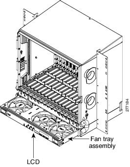
Step 2![]() Install the fan-tray assembly. The fan-tray assembly has locks on the outer edges. Press and hold the locks as you slide the fan-tray assembly into the shelf assembly. The electrical plug at the rear of the tray should plug into the corresponding receptacle on the assembly.
Install the fan-tray assembly. The fan-tray assembly has locks on the outer edges. Press and hold the locks as you slide the fan-tray assembly into the shelf assembly. The electrical plug at the rear of the tray should plug into the corresponding receptacle on the assembly.
Step 3![]() To verify that the tray has plugged into the backplane, look at the fan tray and listen to determine that the fans are running.
To verify that the tray has plugged into the backplane, look at the fan tray and listen to determine that the fans are running.
Figure 1-1 shows the location of the fan tray.
Figure 1-1 Installing the Fan-Tray Assembly
Step 4![]() Continue with the A119 Install the Alarm Expansion Panel if you plan to install an alarm expansion panel (AEP). If not, continue with the A8 Attach Wires to Alarm, Timing, LAN, and Craft Pin Connections.
Continue with the A119 Install the Alarm Expansion Panel if you plan to install an alarm expansion panel (AEP). If not, continue with the A8 Attach Wires to Alarm, Timing, LAN, and Craft Pin Connections.
Stop. You have completed this procedure.
NTP-A119 Install the Alarm Expansion Panel
Note![]() The AIC-I card provides direct alarm contacts (external alarm inputs and external control outputs). In the ANSI shelf, these AIC-I alarm contacts are routed through the backplane to wire-wrap pins accessible from the back of the shelf. When you install an AEP, the direct AIC-I alarm contacts cannot be used. Only the AEP alarm contacts can be used.
The AIC-I card provides direct alarm contacts (external alarm inputs and external control outputs). In the ANSI shelf, these AIC-I alarm contacts are routed through the backplane to wire-wrap pins accessible from the back of the shelf. When you install an AEP, the direct AIC-I alarm contacts cannot be used. Only the AEP alarm contacts can be used.
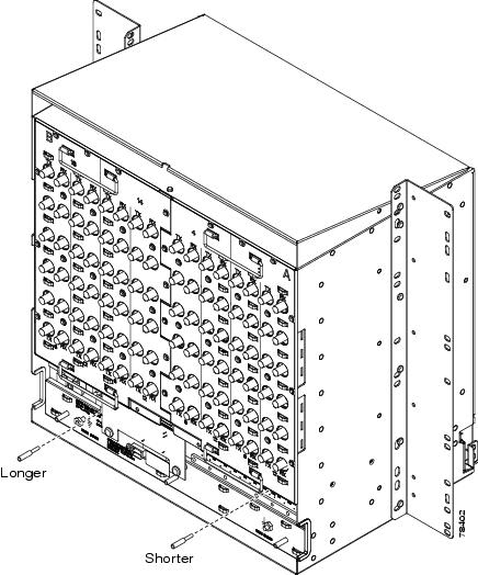
Step 1![]() Remove the two backplane screws. Replace the two screws with standoffs. Insert the longer standoff on the left and the shorter standoff on the right (Figure 1-2).
Remove the two backplane screws. Replace the two screws with standoffs. Insert the longer standoff on the left and the shorter standoff on the right (Figure 1-2).
Figure 1-2 Replace Backplane Screws with Standoffs
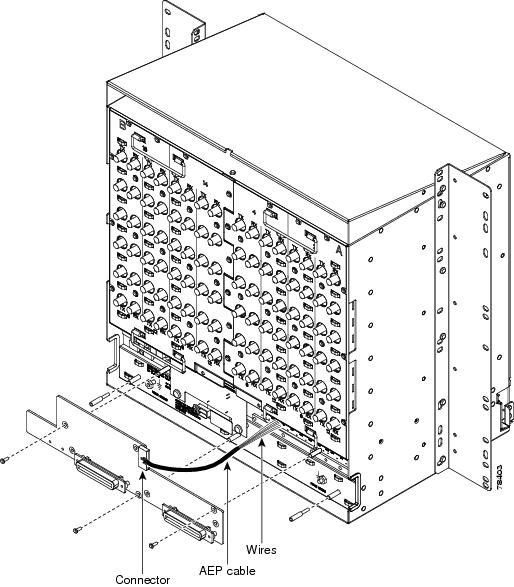
Step 2![]() Attach the remaining two standoffs on either side of the backplane (Figure 1-3).
Attach the remaining two standoffs on either side of the backplane (Figure 1-3).
Step 3![]() Position the AEP board over the standoffs.
Position the AEP board over the standoffs.
Figure 1-3 Installing Standoffs and the AEP
Step 4![]() Insert and tighten three screws to secure the AEP to the backplane.
Insert and tighten three screws to secure the AEP to the backplane.
Step 5![]() Connect the AEP cable to the backplane and AEP:
Connect the AEP cable to the backplane and AEP:
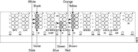
a.![]() Connect the 10 colored wires to the wire-wrap pins on the backplane. Figure 1-4 shows where the cable wires are connected. Table 1-1 shows AEP and AIC-I signals that each wire carries.
Connect the 10 colored wires to the wire-wrap pins on the backplane. Figure 1-4 shows where the cable wires are connected. Table 1-1 shows AEP and AIC-I signals that each wire carries.
b.![]() Plug the other end of the AEP cable into AEP connector port. The brown pin is on the top.
Plug the other end of the AEP cable into AEP connector port. The brown pin is on the top.
Figure 1-4 AEP Wire-Wrap Connections to Backplane Pins
|
|
|
|
|
|---|---|---|---|
Step 6![]() Continue with the A8 Attach Wires to Alarm, Timing, LAN, and Craft Pin Connections.
Continue with the A8 Attach Wires to Alarm, Timing, LAN, and Craft Pin Connections.
Stop. You have completed this procedure.
NTP-A8 Attach Wires to Alarm, Timing, LAN, and Craft Pin Connections
This procedure describes how to install alarm, timing, LAN, and craft wires. |
|
Warning![]() The covers are an integral part of the safety design of the product. Do not operate the unit without the covers installed. Statement 1077
The covers are an integral part of the safety design of the product. Do not operate the unit without the covers installed. Statement 1077
Step 1![]() Complete the A19 Install Alarm Wires on the Backplane if you are using an AIC-I card and are not using an AEP.
Complete the A19 Install Alarm Wires on the Backplane if you are using an AIC-I card and are not using an AEP.
Step 2![]() Complete the A20 Install Timing Wires on the Backplane as needed. Timing wires are necessary to provision external timing.
Complete the A20 Install Timing Wires on the Backplane as needed. Timing wires are necessary to provision external timing.
Step 3![]() Complete the A21 Install LAN Wires on the Backplane as needed. LAN wires (or the LAN port on the TCC2/TCC2P) are necessary to create an external LAN connection.
Complete the A21 Install LAN Wires on the Backplane as needed. LAN wires (or the LAN port on the TCC2/TCC2P) are necessary to create an external LAN connection.
Step 4![]() Complete the A22 Install the TL1 Craft Interface as needed. Craft wires (or the EIA/TIA-232 port on the TCC2/TCC2P) are required to access TL1 using the craft interface.
Complete the A22 Install the TL1 Craft Interface as needed. Craft wires (or the EIA/TIA-232 port on the TCC2/TCC2P) are required to access TL1 using the craft interface.
Step 5![]() Complete one of the following:
Complete one of the following:
- If you installed an AEP, continue with the A120 Install an External Wire-Wrap Panel to the AEP.
- If you did not install an AEP and you plan to install electrical cards, continue with the A9 Install the Electrical Card Cables on the Backplane.
- If you did not install an AEP and do not plan to install electrical cards, continue with the A11 Install the Rear Cover.
Stop. You have completed this procedure.
NTP-A120 Install an External Wire-Wrap Panel to the AEP
This procedure connects an external wire-wrap panel to the AEP to provide the physical alarm contacts for the AEP. |
|
Step 1![]() Position the lower cover over the AEP. Make sure that the AEP AMP Champ connectors protrude through the cutouts in the lower cover (Figure 1-5).
Position the lower cover over the AEP. Make sure that the AEP AMP Champ connectors protrude through the cutouts in the lower cover (Figure 1-5).
Figure 1-5 Installing the AEP Cover
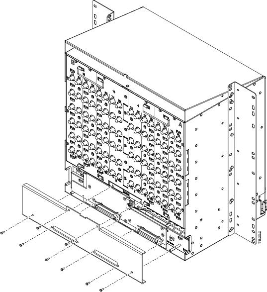
Step 2![]() Insert and tighten the eight screws to secure the AEP cover to the AEP.
Insert and tighten the eight screws to secure the AEP cover to the AEP.
Step 3![]() Connect the cables from the external wire-wrap panel to the AMP Champ connectors on the AEP. Table 1-2 lists the alarm input pin assignments.
Connect the cables from the external wire-wrap panel to the AMP Champ connectors on the AEP. Table 1-2 lists the alarm input pin assignments.
|
|
|
|
|
|---|---|---|---|
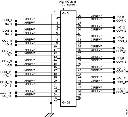
Table 1-3 lists the alarm output pin assignments.
|
|
|
|
|
|---|---|---|---|
Figure 1-6 illustrates the alarm input connectors.
Figure 1-6 Alarm Input Connector
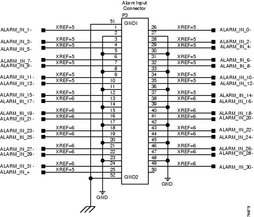
Figure 1-7 illustrates the alarm output connectors.
Figure 1-7 Alarm Output Connector
Step 4![]() Complete one of the following:
Complete one of the following:
- If you plan to install electrical cards, continue with the A9 Install the Electrical Card Cables on the Backplane.
- If you do not plan to install electrical cards, continue with the A11 Install the Rear Cover.
Stop. You have completed this procedure.
NTP-A9 Install the Electrical Card Cables on the Backplane
Note![]() Refer to the Cisco ONS 15454 Reference Manual for more information about EIAs.
Refer to the Cisco ONS 15454 Reference Manual for more information about EIAs.
Step 1![]() Complete the A530 Install the Tie-Down Bar as needed for routing the electrical cables you will install.
Complete the A530 Install the Tie-Down Bar as needed for routing the electrical cables you will install.
Step 2![]() Complete the A23 Install DS-1 Cables Using Electrical Interface Adapters (Balun) as needed. Baluns are used on SMB EIAs to properly terminate DS-1 signals.
Complete the A23 Install DS-1 Cables Using Electrical Interface Adapters (Balun) as needed. Baluns are used on SMB EIAs to properly terminate DS-1 signals.
Step 3![]() To install DS-1 cables using AMP Champ cables, complete the A24 Install DS-1 AMP Champ Cables on the AMP Champ EIA.
To install DS-1 cables using AMP Champ cables, complete the A24 Install DS-1 AMP Champ Cables on the AMP Champ EIA.
Step 4![]() Complete the A25 Install Coaxial Cable With BNC Connectors as needed.
Complete the A25 Install Coaxial Cable With BNC Connectors as needed.
Step 5![]() Complete the A26 Install Coaxial Cable With High-Density BNC Connectors as needed.
Complete the A26 Install Coaxial Cable With High-Density BNC Connectors as needed.
Step 6![]() Complete the A27 Install Coaxial Cable with SMB Connectors as needed.
Complete the A27 Install Coaxial Cable with SMB Connectors as needed.
Step 7![]() Complete the A386 Install Electrical Cables on the UBIC-V EIAs as needed.
Complete the A386 Install Electrical Cables on the UBIC-V EIAs as needed.
Step 8![]() Complete the A441 Install Electrical Cables on the UBIC-H EIAs as needed.
Complete the A441 Install Electrical Cables on the UBIC-H EIAs as needed.
Step 9![]() Continue with the A10 Route Electrical Cables.
Continue with the A10 Route Electrical Cables.
Stop. You have completed this procedure.
NTP-A10 Route Electrical Cables
This procedure routes and manages electrical (backplane) cables. |
|
RG179, RG59 (735A) #26 AWG cable, or RG59 (734A) #20 AWG cable |
|
Step 1![]() Complete the A28 Route Coaxial Cables as needed.
Complete the A28 Route Coaxial Cables as needed.
Step 2![]() Complete the A29 Route DS-1 Twisted-Pair Cables as needed.
Complete the A29 Route DS-1 Twisted-Pair Cables as needed.
Step 3![]() Continue with the A11 Install the Rear Cover.
Continue with the A11 Install the Rear Cover.
Stop. You have completed this procedure.
NTP-A11 Install the Rear Cover
Step 1![]() Identify the EIA type where you will install the rear cover.
Identify the EIA type where you will install the rear cover.
Step 2![]() According to Table 1-4, assemble the extended standoffs for that EIA type. Start with a 1 3/8-inch standoff and attach the other standoff(s) to that standoff to create an extended standoff. You should assemble two extended standoffs for each side, for a total of four extended standoffs per shelf.
According to Table 1-4, assemble the extended standoffs for that EIA type. Start with a 1 3/8-inch standoff and attach the other standoff(s) to that standoff to create an extended standoff. You should assemble two extended standoffs for each side, for a total of four extended standoffs per shelf.
|
|
|
|
|---|---|---|
Note![]() As needed, attach additional standoffs to the extended standoffs to meet site-specific cable management requirements.
As needed, attach additional standoffs to the extended standoffs to meet site-specific cable management requirements.
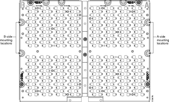
Step 3![]() Locate the mounting holes where you will install the standoffs on the EIAs you are using. Figure 1-8 shows the mounting holes on the UBIC-V. Figure 1-9 shows the mounting holes on the UBIC-H. Figure 1-10 shows the mounting holes on the remaining EIA types (MiniBNC, SMB, etc.). You can identify the mounting holes on all EIAs by locating the REAR COVER BRACKET LOCATION designation.
Locate the mounting holes where you will install the standoffs on the EIAs you are using. Figure 1-8 shows the mounting holes on the UBIC-V. Figure 1-9 shows the mounting holes on the UBIC-H. Figure 1-10 shows the mounting holes on the remaining EIA types (MiniBNC, SMB, etc.). You can identify the mounting holes on all EIAs by locating the REAR COVER BRACKET LOCATION designation.
Figure 1-8 Mounting Holes on the UBIC-V EIA
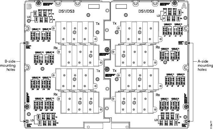
Figure 1-9 Mounting Holes on the UBIC-H
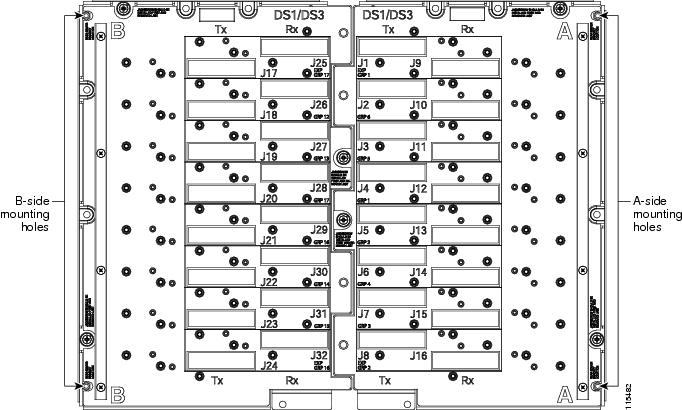
Figure 1-10 Mounting Holes on All Other EIA Types
Step 4![]() Use a 5/16-inch nutdriver to install the extended standoffs in the mounting holes.
Use a 5/16-inch nutdriver to install the extended standoffs in the mounting holes.
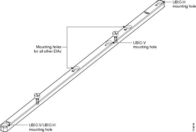
Step 5![]() Locate the TOP designation on one of the mounting bars (700-19701-XX) and align the appropriate holes for your EIA with the extended standoffs (Figure 1-11).
Locate the TOP designation on one of the mounting bars (700-19701-XX) and align the appropriate holes for your EIA with the extended standoffs (Figure 1-11).
Figure 1-11 EIA Labeling on the Mounting Bar
Step 6![]() Tighten the two screws (48-2116-01) for each mounting bar.
Tighten the two screws (48-2116-01) for each mounting bar.
Step 7![]() Repeat Steps 5 and 6 for the second mounting bar.
Repeat Steps 5 and 6 for the second mounting bar.
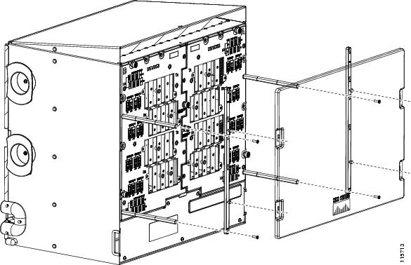
Step 8![]() Attach the rear cover (700-06029-XX) by hanging it from the mounting screws on the back of the mounting bars and pulling it down until it fits firmly into place (Figure 1-12) or by using standoffs (Figure 1-13).
Attach the rear cover (700-06029-XX) by hanging it from the mounting screws on the back of the mounting bars and pulling it down until it fits firmly into place (Figure 1-12) or by using standoffs (Figure 1-13).
Figure 1-12 Installing the Rear Cover Onto the Mounting Bars
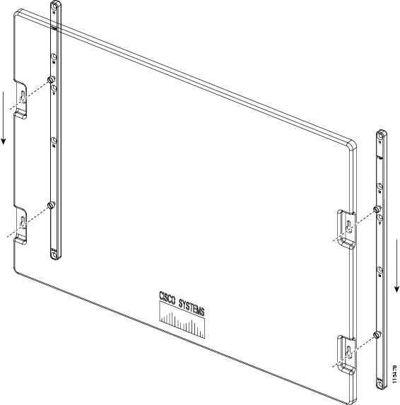
Figure 1-13 Installing the Rear Cover with Standoffs
Stop. You have completed this procedure.
NTP-A13 Perform the Shelf Installation Acceptance Test
Use this procedure to perform a shelf installation acceptance test. |
|
Warning![]() The covers are an integral part of the safety design of the product. Do not operate the unit without the covers installed.
The covers are an integral part of the safety design of the product. Do not operate the unit without the covers installed.
Step 1![]() Complete Table 1-5 by verifying that each applicable procedure was completed.
Complete Table 1-5 by verifying that each applicable procedure was completed.
|
|
|
|---|---|
|
|
|
|
|
|
|
|
|
|
|
|
|
|
|
|
|
|
|
|
|
|
|
|
A8 Attach Wires to Alarm, Timing, LAN, and Craft Pin Connections |
|
|
|
|
|
|
|
|
|
|
|
|
Step 2![]() Complete the A32 Inspect the Shelf Installation and Connections.
Complete the A32 Inspect the Shelf Installation and Connections.
Step 3![]() Complete the A33 Measure Voltage.
Complete the A33 Measure Voltage.
Step 4![]() Continue with Chapter2, “Install Cards and Fiber-Optic Cable”
Continue with Chapter2, “Install Cards and Fiber-Optic Cable”
Stop. You have completed this procedure.
 Feedback