- 5.1 Path Protection Topology
- 5.2 Path Protection Cross-Connections
- 5.3 Ring-to-Ring Interconnection
- 5.3.1 Sample Path Protection to Path Protection Connection
- 5.3.2 Sample Path Protection to Two-Fiber BLSR Connection
- 5.3.3 Sample Two-Fiber BLSR to Path Protection Connection
- 5.3.4 Sample Two-Fiber BLSR to Two-Fiber BLSR Connection
- 5.3.5 Sample Two-Fiber BLSR to Four-Fiber BLSR Connection (ONS 15454)
- 5.3.6 Sample Path Protection to Four-Fiber BLSR Connection (ONS 15454)
- 5.4 1-Way Drop and Continue
Ring Provisioning

Note ![]() The terms "Unidirectional Path Switched Ring" and "UPSR" may appear in Cisco literature. These terms do not refer to using Cisco ONS 15xxx products in a unidirectional path switched ring configuration. Rather, these terms, as well as "Path Protected Mesh Network" and "PPMN," refer generally to Cisco's path protection feature, which may be used in any topological network configuration. Cisco does not recommend using its path protection feature in any particular topological network configuration.
The terms "Unidirectional Path Switched Ring" and "UPSR" may appear in Cisco literature. These terms do not refer to using Cisco ONS 15xxx products in a unidirectional path switched ring configuration. Rather, these terms, as well as "Path Protected Mesh Network" and "PPMN," refer generally to Cisco's path protection feature, which may be used in any topological network configuration. Cisco does not recommend using its path protection feature in any particular topological network configuration.
This chapter provides information and sample procedures for setting up STS or VT circuits over existing path protection and bidirectional line switch ring (BLSR) configurations using TL1, including:
•![]() Path Protection topology
Path Protection topology
•![]() Path Protection cross-connections
Path Protection cross-connections
•![]() Ring-to-ring interconnection
Ring-to-ring interconnection
•![]() 1-way drop and continue
1-way drop and continue
Note ![]() Because the ONS 15454, ONS 15327, ONS 15310-CL and ONS 15600 implements logical path protection, there are no defined east and west ports. Instead, the east STS path for one circuit can exit a different port than the east STS path of another circuit, even though the west STS paths for both circuits may share the same port.
Because the ONS 15454, ONS 15327, ONS 15310-CL and ONS 15600 implements logical path protection, there are no defined east and west ports. Instead, the east STS path for one circuit can exit a different port than the east STS path of another circuit, even though the west STS paths for both circuits may share the same port.
Note ![]() The ONS 15310-CL does not support BLSR.
The ONS 15310-CL does not support BLSR.
Note ![]() The ONS 15600 does not support four-fiber BLSR.
The ONS 15600 does not support four-fiber BLSR.
5.1 Path Protection Topology
No special configuration of the physical path protection topology is required other than connecting the fibers to the desired ports on the desired nodes. The east and west paths must exit a node at different ports (to ensure link diversity), but there are no other physical topology restrictions
ONS 15xxx networks give you the option to set up path-protected mesh networks (PPMNs). PPMNs extend the protection scheme of a path protection from the basic ring configuration to the meshed architecture of several interconnected rings. For more information about PPMN, refer to the Cisco Procedure Guide applicable to your platform.
5.2 Path Protection Cross-Connections
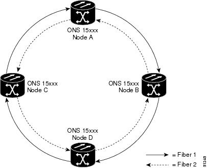
To create a path protection cross-connection using TL1, you only need to designate whether it is a 1-way or 2-way cross-connect, but the access identifier (AID) must be more explicit. For example, to create a 1-way path protection circuit over the network with nodes A, B, C, and D and segments A-B, B-D, A-C, C-D as shown in Figure 5-1, enter the following commands (Node A is the source node and Node D is the destination node):
ENT-CRS-STS1:A:FROM,TO1&TO2:CTAG1::1WAY;
ENT-CRS-STS1:B:FROM,TO:CTAG2::1WAY;
ENT-CRS-STS1:C:FROM,TO:CTAG3::1WAY;
ENT-CRS-STS1:D:FROM1&FROM2,TO:CTAG4::1WAY;
Figure 5-1 Network Configured With a 1-Way Path Protection Circuit
5.3 Ring-to-Ring Interconnection
In the following examples, the form "5/1/1" represents "Slot 5, Port 1, STS 1." For VTs add the normal VT Group and VT ID extensions. These examples also assume that the slots/ports have been auto-provisioned (via a plug-in event) and that the ports involved have been placed into the in service state using a port configuration command, for example, ED-OCN.
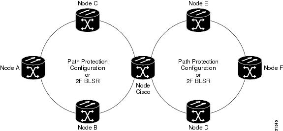
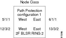
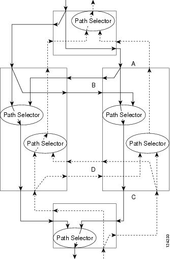
For the examples in this section, both rings traverse the same node; therefore, only a single cross-connection is required to create the ring-to-ring connection. Use the network map shown in Figure 5-2 with the node named "Cisco" in the nexus.
Figure 5-2 Network Map With Cisco Node Showing Ring-to-Ring Interconnection
5.3.1 Sample Path Protection to Path Protection Connection
Ring 1 = Path Protection
Ring 2 = Path Protection
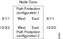
This example, illustrated in Figure 5-3, uses a OC-3-4 to feed Ring 2. Ring 1 can have any OC-N trunk card, but the trunk card is most likely a single-port OC-48 or OC-12.
Note ![]() STS 12/3/2 maps to STS-12-8 (((3-1)*3) +2).
STS 12/3/2 maps to STS-12-8 (((3-1)*3) +2).
The STS calculation formula is: (((Port # -1)*Number of STS per port)+STS#).
Figure 5-3 Path Protection to Path Protection Connection Specifications Through the Cisco Node
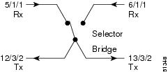
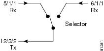
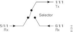
Use the ENT-CRS-STS1:CISCO:STS-5-1&STS-6-1,STS-12-8&STS-13-8:CTAG1::2WAY;
to create a selector between 5/1/1 and 6/1/1 which is bridged to Ring 2 (12/3/2 and 13/3/2), as shown in Figure 5-4.
Figure 5-4 Selector Between 5/1/1 and 6/1/1
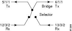
The command also creates a selector between 12/3/2 and 13/3/2 to a bridge to Ring 1 (5/1/1 and 6/1/1), as shown in Figure 5-5.
Figure 5-5 Selector Between 12/3/2 and 13/3/2
5.3.2 Sample Path Protection to Two-Fiber BLSR Connection
Ring 1 = Path Protection
Ring 2 = Two-fiber BLSR
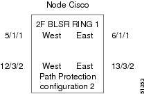
This example, illustrated in Figure 5-6, uses a path protection end-point with a drop on a two-fiber BLSR and the west span of the two-fiber BLSR (Ring 2) for the active path of the circuit. The example also uses multiport addressing for Ring 2 and is based on a multiport OC12-4 card (this is only important for computing the STS AID for multiport cards) where 13/3/2 = STS-13-26 and where
26 = (((3-1)*12) +2).
Figure 5-6 Path Protection to Two-Fiber BLSR
Use the ENT-CRS-STS1:CISCO:STS-5-1&STS-6-1,STS12-26:CTAG2::2WAY;
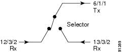
to create a selector between 5/1/1 and 6/1/1 which connects to 12/3/2 on Ring 2, as shown in Figure 5-7.
Figure 5-7 Selector Between 5/1/1 and 6/1/1
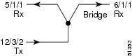
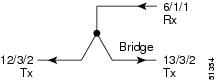
The command also creates a bridge from 12/3/2 to Ring 1 (5/1/1 and 6/1/1), as shown in Figure 5-8.
Figure 5-8 Bridge from 12/3/2 to Ring 1
In this configuration a two-fiber BLSR switch can automatically reconnect the selector output to the protection path on the east port (12/3/2 assuming OC-12) if necessary.
5.3.3 Sample Two-Fiber BLSR to Path Protection Connection
Ring 1 = Two-fiber BLSR
Ring 2 = Path Protection
This example, illustrated in Figure 5-9, uses a Path Protection end-point with a drop on a two-fiber BLSR and uses the east span of the two-fiber BLSR (Ring 1) for the active path of the circuit. For STS addressing, the path protection is an OC-3 (e.g. STS-13-8).
Figure 5-9 Two-Fiber BLSR to Path Protection
Use the ENT-CRS-STS1:CISCO:STS-6-1,STS-12-8&STS-13-8:CTAG3::2WAY;
to create a bridge from 6/1/1 to Ring 2 (12/3/2 and 13/3/2), as shown in Figure 5-10.
Figure 5-10 Bridge from 6/1/1 to Ring 2
The command also creates a selector between 12/3/2 and 13/3/2 to Ring 1 (6/1/1) as shown in Figure 5-11.
Figure 5-11 Selector Between 12/3/2 and 13/3/2 to Ring 1
5.3.4 Sample Two-Fiber BLSR to Two-Fiber BLSR Connection
Ring 1 = Two-fiber BLSR
Ring 2 = Two-fiber BLSR
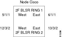
All protection for a two-fiber BLSR interconnecting to a two-fiber BLSR is performed at the line level. You can make the connection with a 2-way cross-connect from an STS on the working side of the two-fiber BLSR span of Ring 1 to an STS on the working side of a two-fiber BLSR span on Ring 2. The connections can be east to east, east to west, west to east, and west to west. This example, illustrated in Figure 5-12, uses Ring 1 west to Ring 2 east and assumes a OC-12-4 in Slots 12 and 13 for subtending to a two-fiber BLSR (Ring 2).
Figure 5-12 Two-Fiber BLSR to Two-Fiber BLSR
Use the ENT-CRS-STS1:CISCO:STS-5-1,STS-13-26:CTAG4::2WAY;
to create a 2-way connection from 5/1/1 to 13/3/2 as shown in Figure 5-13.
Figure 5-13 2-Way Connection from 5/1/1 to 13/3/2
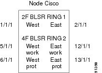
5.3.5 Sample Two-Fiber BLSR to Four-Fiber BLSR Connection (ONS 15454)
Ring 1 = Two-fiber BLSR
Ring 2 = Four-fiber BLSR
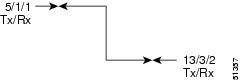
All protection for a two-fiber BLSR interconnecting to a four-fiber BLSR is performed at the line level. You can make the connection with a simple 2-way cross-connect from the appropriate side, east or west, of the two-fiber BLSR to the working fiber of the appropriate side, east or west, of the four-fiber BLSR, as shown in Figure 5-14.
Figure 5-14 Two-Fiber BLSR to Four-Fiber BLSR
Use the ENT-CRS-STS1:CISCO:STS-1-1,STS-5-1:CTAG5::2WAY;
to create a 2-way connection from 1/1/1 to 5/1/1, as shown in Figure 5-15.
Figure 5-15 2-Way Connection from 1/1/1 to 5/1/1
In the event of a failure, the software will automatically switch the traffic to the appropriate line and path.
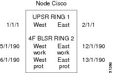
5.3.6 Sample Path Protection to Four-Fiber BLSR Connection (ONS 15454)
Ring 1 = Path Protection
Ring 2 = Four-fiber BLSR
This example uses the west span of the four-fiber BLSR (Ring 2) for the active path of the circuit. The example also assumes that the four-fiber BLSR travels over OC-192 spans, as shown in Figure 5-16.
Figure 5-16 Path Protection to Four-Fiber BLSR
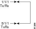
Use the ENT-CRS-STS1:CISCO:STS-1-1&STS-2-1&STS-5-190:CTAG6::2WAY;
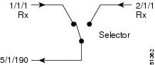
to create a selector between 1/1/1 and 2/1/1 to Ring 2 (5/1/190), as shown in Figure 5-17.
Figure 5-17 Selector Between 1/1/1 and 2/1/1 to Ring 2 (5/1/190)
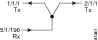
The command also creates a bridge from 5/1/190 to Ring 1 (1/1/1 and 2/1/1), as shown in Figure 5-18.
Figure 5-18 Bridge From 5/1/190 to Ring 1 (1/1/1 and 2/1/1)
5.4 1-Way Drop and Continue
The following examples show how to create a 1-way drop and continue cross-connect. The examples use three nodes (Node 1, Node 2, and Node 3) in a ring configuration (Figure 5-19). Node 1 is the source node, Node 2 has the drop and continue, and Node 3 is the destination.
Figure 5-19 1-Way Drop and Continue

Figure 5-20 shows a circuit diagram example of the orientation of AIDs associated with the ENT-CRS command used to establish drop and continue connections.
Figure 5-20 Orientation of AIDs Used to Establish Drop and Continue Connections
5.4.1 Sample Node 1 Configuration (Source Node)
Issue the ENT-CRS-STSn::STS-1-1,STS-5-1&STS-6-1:CTAG::1WAY; command on Node 1.
Figure 5-21 Bridge from 1/1/1 to 5/1/1 and 6/1/1
5.4.2 Sample Node 2 Configuration (Drop and Continue Node)
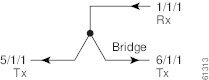
Issue the ENT-CRS-STSn::STS-5-1&STS-6-1,STS-1-1:CTAG::1WAYDC; on Node 2.
Figure 5-22 Selector Between 5/1/1 and 6/1/1 to 1/1/1
5.4.3 Sample Node 3 Configuration (Destination Node)
Issue the ENT-CRS-STSn::STS-5-1&STS-6-1,STS-1-1:CTAG::1WAY; on Node 3.
Figure 5-23 Selector Between 5/1/1 and 6/1/1 to 1/1/1
 Feedback