| Step 4 |
To create a C Series Blueprint:
-
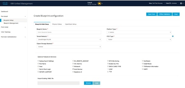
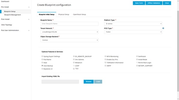
On the Blueprint Initial Setup page of the Cisco VIM Unified Management, complete the following fields:
|
Name
|
Description
|
|
Blueprint Name field.
|
Enter the name for the blueprint configuration.
|
|
Platform Type drop-down list
|
Choose one of the following platform types:
|
|
Tenant Network drop-down list
|
Choose one of the following tenant network types:
-
Linux Bridge/VXLAN
-
OVS/VLAN
-
VTS/VLAN
-
VPP/VLAN
-
ACI/VLAN
| Note
|
when VTS/VLAN or ACI/VLAN is selected then respective tabs are available on Blueprint setup. When Mechanism driver OVS or
ACI is selected, VM_HUGEPAGE_PERCENTAGE field is enabled for all standalone compute nodes, when NFV_HOSTS is enabled.
|
|
|
Pod Type drop-down list
|
Choose one of the following pod type :
-
Fullon(By Default)
-
Micro
-
UMHC
-
NGENAHC
| Note
|
-
UMHC pod type is only supported for OVS/VLAN tenant type.
-
NGENAHC is supported for VPP/VLAN tenant type with no SRIOV
-
Pod type micro is supported for OVS/VLAN, ACI/VLAN,VPP/VLAN.
|
|
|
Ceph Mode drop-down list
|
Choose one of the following Ceph types:
|
|
Optional and Services Features checkbox
|
Swiftstack, LDAP, Syslog Export Settings, Install Mode, TorSwitch Information, TLS, NFVMON, Pod Name, VMTP, NFVBench, Autbackup,
Heat, Keystone v3, Enable Esc Priv.
If any one is selected, the corresponding section is visible in various Blueprint sections.
By default all features are disabled except Auto Backup.
|
|
Import Existing YAML file
|
If you have an existing C Series YAML file you can use this feature to upload the file.
Unified Management will automatically fill in the fields and any missed mandatory field will be highlighted in the respective
section.
|
-
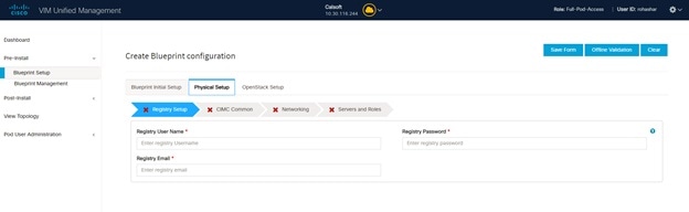
Click Physical Setup to advance to the Registry Setup configuration page. Fill in the following details for Registry Setup:
|
Name
|
Description
|
|
Registry User Name text field
|
User-Name for Registry (Mandatory).
|
|
Registry Password text field
|
Password for Registry (Mandatory).
|
|
Registry Email text field
|
Email ID for Registry (Mandatory).
|
Once all the mandatory fields are filled the Validation Check Registry Page will be changed to a Green Tick.
-
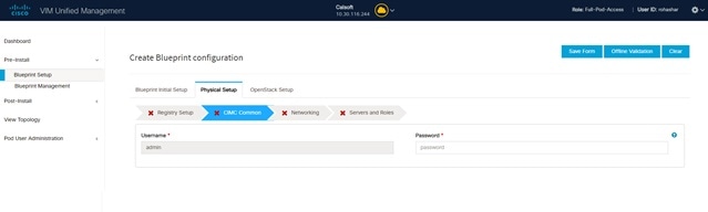
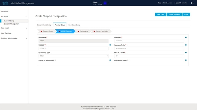
Click CIMC Common Tab and complete the following fields:
|
Name
|
Description
|
|
User Name disabled field
|
By default value is Admin.
|
|
Password text field
|
Enter Password for UCSM Common (Mandatory).
|
-
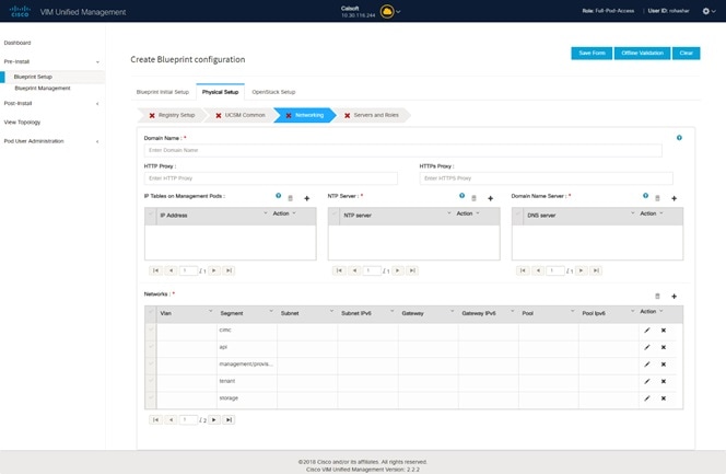
Click Networking to advance to the networking section of the Blueprint.
|
Name
|
Description
|
|
Domain Name field
|
Enter the domain name. (Mandatory)
|
|
HTTP Proxy Server field
|
If your configuration uses an HTTP proxy server, enter the IP address of the server.
|
|
HTTPS Proxy Server field
|
If your configuration uses an HTTPS proxy server, enter the IP address of the server.
|
|
IP Tables on Management Pods
|
Specifies the list of IP Address with Mask.
|
|
NTP Servers field
|
Enter a maximum of four and minimum of one IPv4 and/or IPv6 addresses in the table.
|
|
Domain Name Servers field
|
Enter a maximum of three and minimum of one IPv4 and/or IPV6 addresses.
|
|
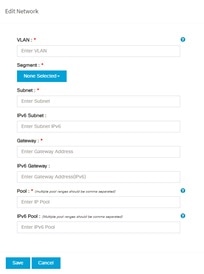
Networks table
|
Network table is pre-populated with Segments. To add Networks you can either clear all the table with Delete all or click edit icon for each segment and fill in the details.
You can add, edit, or delete network information in the table.
|
Name
|
Description
|
|
VLAN field
|
Enter the VLAN ID.
For Segment - Provider, the VLAN ID value is 'none'.
|
|
Segment drop-down list
|
When you add/edit new segment then following segments types are available in the form of dropdown list and you can select
only one.
-
API
-
Management/provision
-
Tenant
-
Storage
-
External
-
Provider
-
ACIINFRA
| Note
|
Aciinfra segment is available only when ACI/VLAN tenant type is selected) Depending upon the segment some of the entries below are
not needed. Please refer to the example file in openstack-configs dir for details.
|
|
|
Subnet field
|
Enter the IPv4 address for the subnet.
|
|
IPv6 Subnet field
|
Enter IPv6 Address. This field will be available only for Management provision and API
|
|
Gateway field
|
Enter the IPv4 address for the Gateway.
|
|
Gateway IPv6 field
|
Enter the IPv6 address for the gateway. This will support for API and management provision.
|
|
Pool field
|
Enter the pool information in the required format, for example: 10.1.1.5-10.1.1.10,10.2.1.5-10.2.1.10
This field is available only for the Mgmt/Provision, Storage, and Tenant segments.
|
|
IPv6 Pool field
|
Enter the pool information in the required format. For example: 10.1.1.5-10.1.1.10,10.2.1.5-10.2.1.10
|
|
Click Save.
|
|
-
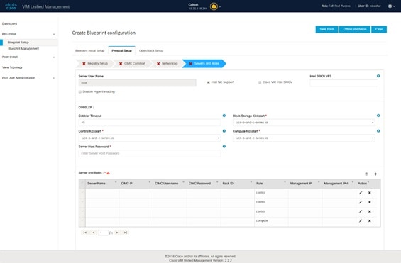
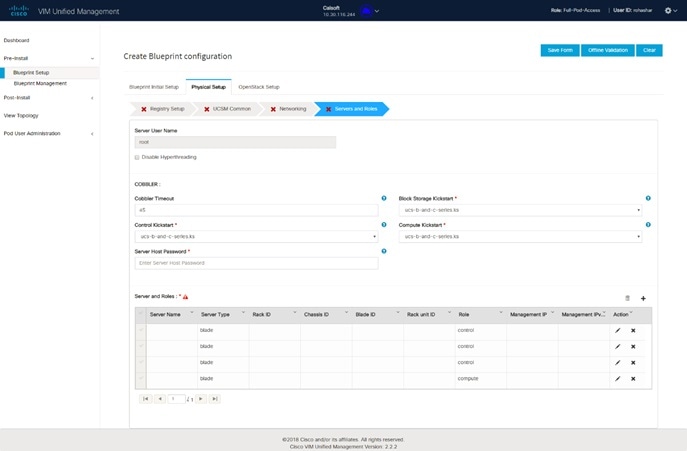
On the Servers and Roles page of the Cisco VIM Suite wizard, a pre-populated table filled with Roles : Control, Compute and Block Storage (Only if
CEPH Dedicated is selected in Blueprint Initial Setup is available.
| Note
|
If you choose mechanism driver as OVS or ACI, VM_HUGEPAGE_PERCENTAGE field column is available for compute nodes, where you
can fill values from 0 to 100%, when NFV_HOSTS: ALL is chosen.
|
|
Name
|
Description
|
|
Server User Name field
|
Enter the username of the Server.
|
|
Disable Hyperthreading
|
Default value is false. You can set it as true or false. |
|
Cobbler
|
Enter the Cobbler details in the following fields:
|
Name
|
Description
|
|
Cobbler Timeout field
|
The default value is 45 min.
This is an optional parameter. Timeout is displayed in minutes, and its value ranges from 30 to 120.
|
|
Block Storage Kickstart field
|
Kickstart file for Storage Node.
|
|
Admin Password Hash field
|
Enter the Admin Password. Password should be Alphanumeric. Password should contain minimum 8 characters and maximum of 32
characters.
|
|
Cobbler Username field
|
Enter the cobbler username to access the cobbler server.
|
|
Control Kickstart field
|
Kickstart file for Control Node.
|
|
Compute Kickstart field
|
Kickstart file for Compute Node.
|
|
Cobbler Admin Username field
|
Enter the admin username of the Cobbler.
|
|
|
Add Entry to Servers and Roles
| Note
|
when Pod type micro is selected then all the three servers will be associated with control, compute and block storage role.
|
For Example:
Roles
-
Block Storage
-
-Server 1
-
-Server 2
-
-Server 3
-
Control
-
-Server 1
-
-Server 2
-
-Server 3
-
Compute
-
-Server 1
-
-Server 2
-
-Server 3
| Note
|
When Pod type UMHC is selected then auto ToR configuration is not supported and the ToR info at server and roles level is
not allowed to be entered.
|
|
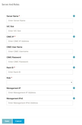
Click Edit or + to add a new server and role to the table.
If mechanism driver is either OVS or ACI, an additional optional field VM_HUGEPAGE_PERCENTAGE is shown when compute role is
chosen; This option is only valid when NFV_HOSTS is set to ALL; If no value is entered then the global value of VM_HUGEPAGE_PERCENTAGE
is used.
|
Server Name
|
Entry the name of the server.
|
|
Rack ID field
|
The rack ID for the server.
|
|
VIC Slot field
|
Enter a VIC Slot.
|
|
CIMC IP field
|
Enter a IP address.
|
|
CIMC Username field
|
Enter a Username.
|
|
CIMC Password field
|
Enter a Password for CIMC.
|
|
Select the Role from the drop down list
|
Choose Control or Compute or Block Storage from the drop-down list.
|
|
Management IP
|
It is an optional field but if provided for one Server then it is mandatory to provide it for other Servers as well.
|
|
Management IPv6
|
Routable and valid IPv6 address. It is an optional field but if provided for one server then it is mandatory for all other
servers as well.
|
|
|
Click Save or Add .
|
On clicking Save or Add all information related to Servers and Roles gets saved.
|
|
If Configure ToR checkbox is Truewith at-least one switch detail, these fields will be displayed for each server and this is similar to DP Tor: Port Channel and Switch Name (Mandatory if Configure ToR is true)
|
-
Port Channel field
-
Switch Name field
-
Switch Port Info field
|
|
|
DP ToR (Only for Control and Compute) : Mandatory if Intel NIC and Configure TOR is True.
|
-
Port Channel field
-
Switch Name field
-
Switch Port Info field
|
|
|
SRIOV TOR INFO (Only for Compute Nodes). It is mandatory in server and roles if Intel NIC and Configure TOR is True. with TOR TYPE Nexus.
For TOR TYPE NCS-5500 these fields are optional Switch Name (Mandatory if Configure ToR is true). This field appears only when Intel NIC support is true, as Auto TOR config is not supported in VIC_NIC combo
|
-
Switch Name field
-
Switch Port Info field
|
|
|
Intel SRIOV VFS (valid for Intel NIC testbeds) and can be integer.
|
For SRIOV support for Intel NIC. By Default, SRIOV support is disabled. To enable, define a value in the range # * 1-32 when
INTEL_NIC_SUPPORT is set True (X710 Max VFs = 32) # * 1-63 when CISCO_VIC_INTEL_SRIOV is set True (X520 Max VFs = 63)
|
|
INTEL_SRIOV_PHYS_PORTS (valid for Intel NIC test beds) and can be of value 2 or 4 (default is 2)
|
In some cases the # of Physical SRIOV port needed is 4; to meet that requirement, define the following: # this is optional,
if nothing is defined code will assume it to be 2; the only 2 integer values this parameter # takes is 2 or 4 and is true
when INTEL_NIC_SUPPORT is True and INTEL_SRIOV_VFS is valid.. For Cisco NCS 5500 this value is set to 4 and is non-editable.
|
|
Click Save or Add .
|
If all mandatory fields are filled click Save or Add to add information on Servers and Roles.
|
|
Disable Hyperthreading
|
Default value is false. You can set it as true or false. |
|
Click Save
|
|
| Note
|
Maximum two ToR info needs to be configured for each connection type on each node (control, compute and block_storage node).
|
| Note
|
If pod type UMHC is selected then CISCO_VIC_INTEL_SRIOV is enabled to be TRUE. CISCO_VIC_INTEL_SRIOV is also supported on
Micro pod with expanded computes
|
| Note
|
For Tenant type ACI/VLAN, port channel for each ToR port will not be available in servers and roles, as APIC will automatically assign port-channel
numbers. Also, for ACI in full on mode you can select Intel NIC Support in the “Servers and Roles” section.
|
-
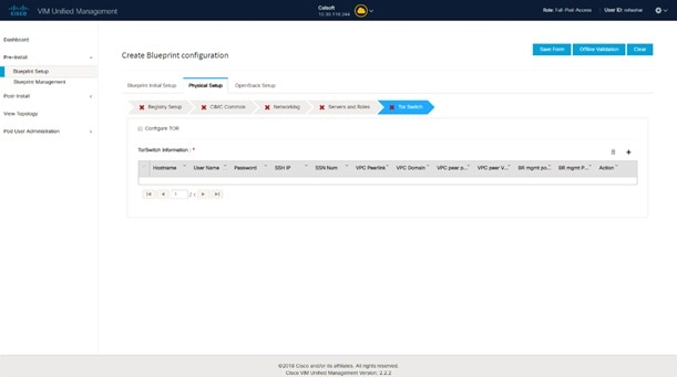
Click ToR Switch checkbox in Blueprint Initial Setup to enable the TOR SWITCH configuration page. It is an Optional section in Blueprint Setup but once all the fields are filled in then it will become a part of the Blueprint.
|
Name
|
Description
|
|
Configure ToR optional checkbox.
| Note
|
If UMHC is selected as podtype, configure TOR is not allowed.
|
|
Enabling this checkbox, changes the configure ToR section from false to true.
| Note
|
Configure tor is true then ToR switch info maps in servers
|
|
|
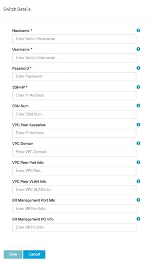
ToR Switch Information mandatory table if you want to enter ToR information.
|
Click (+) to add information for ToR Switch.
|
Name
|
Description
|
|
Name
|
ToR switch name.
|
|
Username
|
ToR switch username.
|
|
Password
|
ToR switch password.
|
|
SSH IP
|
ToR switch SSH IP.
|
|
SSN Num
|
ToR switch ssn num.
|
|
VPC Peer Keepalive
|
Peer Management IP. You cannot define if there is no peer.
|
|
VPC Domain
|
Cannot define if there is no peer.
|
|
VPC Peer Port Info
|
Interface for vpc peer ports.
|
|
VPC Peer VLAN Info
|
VLAN ids for vpc peer ports (optional).
|
|
BR Management Port Info
|
Management interface of build node.
|
|
BR Management PO Info
|
Port channel number for management interface of build node.
|
|
BR Management VLAN info
|
VLAN id for management interface of build node (access).
|
|
|
Click Save.
|
| Note
|
When tenant type ACI/VLAN is selected, the TOR switch information table differs and is mandatory.
|
|
Name
|
Description
|
|
Configure ToR optional checkbox.
| Note
|
If UMHC is selected as podtype, configure TOR is not allowed.
|
|
Enabling this checkbox, changes the configure ToR section from false to true.
| Note
|
Configure tor is true then ToR switch info maps in servers
|
|
|
ToR Switch Information mandatory table if you want to enter ToR information.
|
Click (+) to add information for ToR Switch.
|
Name
|
Description
|
|
Name
|
ToR switch name.
|
|
Username
|
ToR switch username.
|
|
Password
|
ToR switch password.
|
|
SSH IP
|
ToR switch SSH IP.
|
|
SSN Num
|
ToR switch ssn num.
|
|
VPC Peer Keepalive
|
Peer Management IP. You cannot define if there is no peer.
|
|
VPC Domain
|
Cannot define if there is no peer.
|
|
VPC Peer Port Info
|
Interface for vpc peer ports.
|
|
VPC Peer VLAN Info
|
VLAN ids for vpc peer ports (optional).
|
|
BR Management Port Info
|
Management interface of build node.
|
|
BR Management PO Info
|
Port channel number for management interface of build node.
|
|
BR Management VLAN info
|
VLAN id for management interface of build node (access).
|
|
|
Click Save.
|
| Note
|
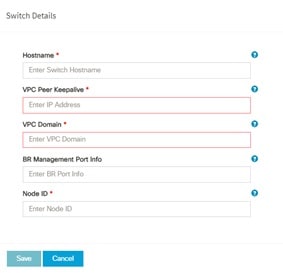
When the Tenant type ACI/VLAN is selected, the ToR switch information table differs and is mandatory.
|
|
Name
|
Description
|
|
Configure ToR
|
Is not checked, as by default ACI will configure the ToRs
|
Host Name
|
ToR switch name.
|
|
VPC Peer keep alive
|
Enter Peer must be exist pair.
|
|
VPC Domain
|
Enter an integer.
|
|
BR management port info
|
Enter BR management port info eg. Eth1/19 ,atleast one pair to be exist.
|
|
Enter Node ID
|
Entered integer must be unique.
|
|
| Note
|
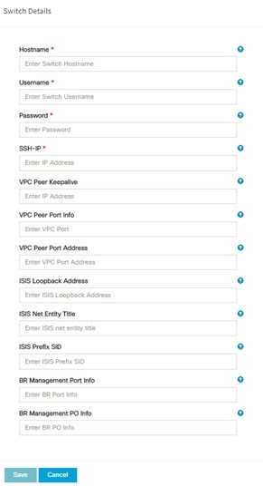
If TOR_TYPE is selected as NCS-5500, the TOR switch information table differs and is mandatory.
|
|
Name
|
Description
|
|
Configure ToR optional checkbox
| Note
|
If NSC-5500 is selected as TOR_TYPE, configure TOR is set as mandatory.
|
|
Enabling this checkbox, changes the configure ToR section from false to true.
| Note
|
Configure TOR is true then ToR switchinfo maps in servers.
|
|
|
If you want to enter NCS details fill in the NCS-5500 Information table.
|
Click (+) to add information for NCS-500 Switch.
|
Name
|
Description
|
|
Name
|
Enter the NCS-5500 hostname.
|
|
User Name
|
Enter the NCS-5500 username.
|
|
Password
|
Enter the NCS-5500 password. |
|
SSH IP
|
Enter the NCS-5500 ssh IP Address.
|
|
VPC Peer Link
|
Peer management IP.
|
|
BR Management PO Info
|
Port channel number for management interface of build node.
|
|
BR Management VLAN info
|
VLAN id for management interface of build node (access).
|
| VPC Peer Port Info
|
Interface for vpc peer ports.
|
| VPC Peer Port Address
|
Address for ISIS exchange.
|
| ISIS Loopback Interface address
|
ISIS loopack IP Address.
|
| ISIS net entity title
|
Enter a String.
|
| ISIS prefix SID
|
Integer between 16000 to 1048575.
|
|
When TOR-TYPE selected as NCS-5500 and 2 NCS-5500 are configured it is mandatory to configure MULTI_SEGMENT_ROUTING_INFO
|
Name
|
Description
|
|
BGP AS Number field
|
Integer between 1 to 65535.
|
|
ISIS Area Tag field
|
A valid string.
|
|
Loopback Interface name field
|
Loopback Interface name.
|
|
API bundle ID field
|
Integer between 1 to 65535.
|
|
API bridge domain field
|
String (Optional, only needed when br_api of mgmt node is also going through NCS-5500; this item and api_bundle_id are mutually
exclusive).
|
|
EXT bridge domain field
|
A valid string (user pre-provisions physical, bundle interface, sub-interface and external BD for external uplink and provides
external BD info setup_data).
|
-
Click NFVI Monitoring checkbox in Blueprint Initial Setup to enable the NFVI Monitoring configuration tab.

|
Name
|
Description
|
| Admin IP |
IP Address of Control Center VM
|
| Management VIP |
VIP for ceilometer/dispatcher to use, must be unique across VIM Pod
|
| Host Name |
Hostname of Collector VM
|
| Password |
Password of Collector VM
|
| CCUSER Password |
Password of CCUSER
|
| Admin IP |
SSH IP of Collector VM
|
| Management IP |
Management IP of Collector VM
|
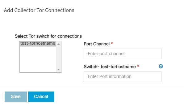
| Collector ToR Connections |
-
Click on (+) icon to Add Collector ToR Connections.
-
Select the ToR switches from list to add the information.
-
It is optional and available for ToR type NCS-5500
-
For now, it supports adding only one Collector ToR Connection
|
Port Channel |
Enter port channel. |
|
Switch - {torSwitch-hostname}
|
Enter port number, E.g:eth1/15. |
Click Save
|
| Rabbit MQ User Name |
Enter Rabbit MQ username.
|
-
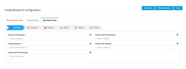
Click OpenStack Setup Tab to advance to the OpenStack Setup Configuration page. On the OpenStack Setup Configuration page of the Cisco VIM Unified Management wizard, complete the following fields:
|
Name
|
Description
|
|
HA Proxy
|
Fill in the following details:

|
External VIP Address field
|
Enter IP address of External VIP.
|
|
External VIP Address IPv6 field
|
Enter IPv6 address of External VIP.
|
|
Virtual Router ID field
|
Enter the Router ID for HA.
|
|
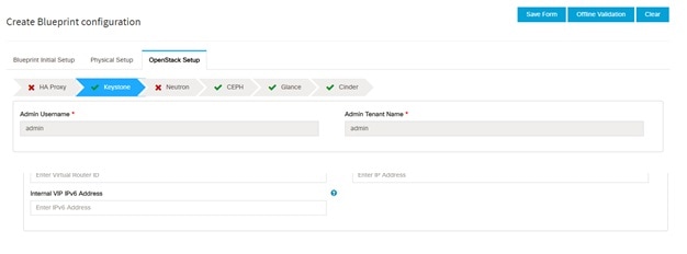
Internal VIP Address IPv6 field
|
Enter IPv6 address of Internal IP.
|
|
Internal VIP Address field
|
Enter IP address of Internal VIP.
|
|
|
Keystone
|
Mandatory fields are pre-populated.
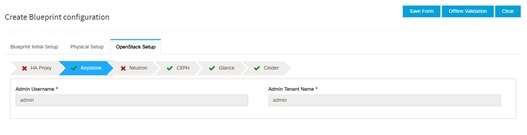
|
Admin User Name
|
admin.
|
|
Admin Tenant Name
|
admin.
|
|
|
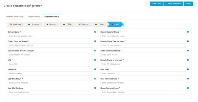
LDAP
|
LDAP enable checkbox which by default is false, if LDAP is enabled on keystone.

|
Domain Name field
|
Enter name for Domain name.
|
|
Object Class for Users field
|
Enter a string as input.
|
|
Object Class for Groups field
|
Enter a string.
|
|
Domain Name Tree for Users field
|
Enter a string.
|
|
Domain Name Tree for Groups field
|
Enter a string.
|
|
Suffix for Domain Name field
|
Enter a string.
|
|
URL field
|
Enter a URL with ending port number.
|
|
Domain Name of Bind User field
|
Enter a string.
|
|
Password field
|
Enter Password as string format.
|
|
User Filter field
|
Enter filter name as string.
|
|
User ID Attribute field
|
Enter a string.
|
|
User Name Attribute field
|
Enter a string.
|
|
User Mail Attribute field
|
Enter a string.
|
|
Group Name Attribute field
|
Enter a string.
|
|
|
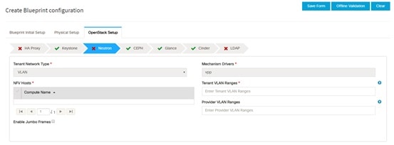
Neutron
|
Neutron fields would change on the basis of Tenant Network Type Selection from Blueprint Initial Setup. Following are the options available for Neutron for OVS/VLAN:
|
Tenant Network Type field
|
Auto Filled based on the Tenant Network Type selected in the Blueprint Initial Setup page.
|
|
Mechanism Drivers field
|
Auto Filled based on the Tenant Network Type selected in Blueprint Initial Setup page.
|
|
NFV Hosts field
|
Auto filled with the Compute you added in Server and Roles.
If you select All in this section NFV_HOSTS: ALL will be added to the Blueprint or you can select one particular compute. For Eg:
NFV_HOSTS: compute-server-1, compute-server-2.
|
|
Tenant VLAN Ranges field
|
List of ranges separated by comma form start:end.
|
|
Provider VLAN Ranges field
|
List of ranges separated by comma form start:end.
|
|
VM Hugh Page Size (available for NFV_HOSTS option) field
|
2M or 1G (optional, defaults to 2M)
|
|
VM_HUGHPAGE_PERCENTAGE
|
Optional, defaults to 100%; can range between 0 and 100
|
|
VSWITCH_WORKER_PROFILE
|
Allowed only for VPP
Optionally available options: numa_zero and even
|
|
NR_RESERVED_VSWITCH_PCORES
|
Allowed only for VPP
Number of cores associated to VPP, defaults to 2.
|
|
Enable Jumbo Frames field
|
Enable the checkbox
|
For Tenant Network Type Linux Bridge everything remains the same but Tenant VLAN Ranges will be removed.
|
|
CEPH
|
-
1. When Object Storage Backend is selected Central in blueprint initial setup. 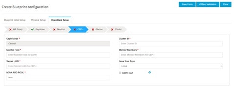
| CEPH Mode |
By default Central. |
| Cluster ID |
Enter Cluster ID. |
| Monitor Host |
Enter Monitor Host for CEPH |
| Monitor Members |
Enter Monitor Members for CEPH |
| Secret UUID |
Enter Secret UUID for CEPH |
| NOVA Boot from |
Drop down selection. You can choose CEPH or local. |
|
NOVA RBD POOL
|
Enter NOVA RBD Pool (default's to vms)
|
|
CEPH NAT
|
Optional, needed for Central Ceph and when mgmt network is not routable
|
-
When Object Storage Backend is selected Dedicated in blueprint initial setup. 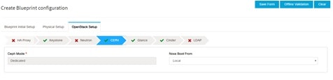 • CEPH Mode: By default Dedicated.
• NOVA Boot: From drop down selection you can choose CEPH or local.
-
When Object Storage Backend is selected NetApp in blueprint initial setup. 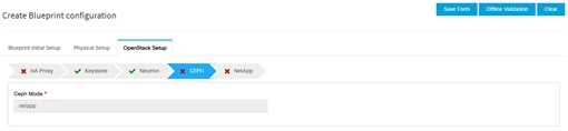
|
|
GLANCE
|
1. When Object Storage Backend is selected Central in blueprint initial setup. 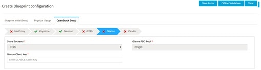 When Object Storage Backend is selected Dedicated in blueprint initial setup. 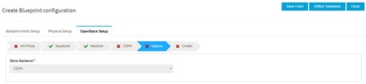
| Note
|
By default Populated for CEPH Dedicated with Store Backend value as CEPH.
|
|
|
CINDER
|
By default Populated for CEPH Dedicated with Volume Driver value as CEPH.
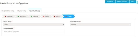 2. When Object Storage Backend is selected Dedicated in blueprint initial setup. 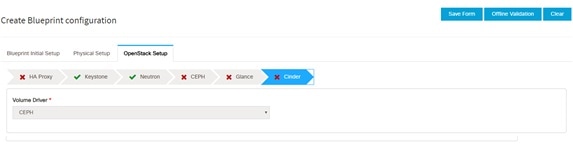
| Note
|
By default Populated for CEPH Dedicated with Volume Driver value as CEPH.
|
|
|
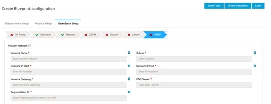
VMTP optional section, this will be visible only if VMTP is selected from Blueprint Initial Setup. For VTS tenant type Provider
network is only supported.
|
Check one of the check boxes to specify a VMTP network:
-
Provider Network
-
External Network
For the Provider Network complete the following:
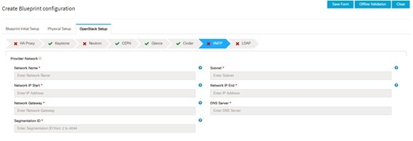
|
Network Name field
|
Enter the name for the external network.
|
|
Subnet field
|
Enter the Subnet for Provider Network.
|
|
Network IP Start field
|
Enter the starting floating IPv4 address.
|
|
Network IP End field
|
Enter the ending floating IPv4 address.
|
|
Network Gatewayfield
|
Enter the IPv4 address for the Gateway.
|
|
DNS Server field
|
Enter the DNS server IPv4 address.
|
|
Segmentation ID field
|
Enter the segmentation ID.
|
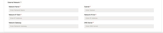
For External Network fill in the following details:
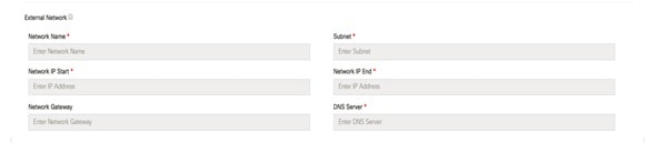
|
Network Name field
|
Enter the name for the external network.
|
|
IP Start field
|
Enter the starting floating IPv4 address.
|
|
IP End field
|
Enter the ending floating IPv4 address.
|
|
Gateway field
|
Enter the IPv4 address for the Gateway.
|
|
DNS Server field
|
Enter the DNS server IPv4 address.
|
|
Subnet field
|
Enter the Subnet for External Network.
|
|
|
TLS optional section, this will be visible only if TLS is selected from Blueprint Initial Setup Page.
|
TLS has two options:
|
|
Under the OpenStack setup tab, Vim_admins tab will be visible only when Vim_admins is selected from the Optional Features
& Services under the Blueprint Initial setup tab
|
Following are the field descriptions for VIM Admins:
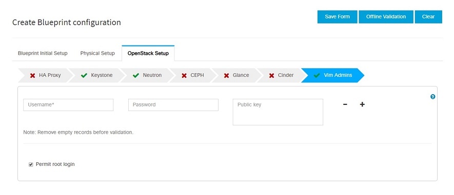
|
User Name
|
Enter username
|
|
Password
|
Password field. Admin hash password should always start with $6.
|
|
|
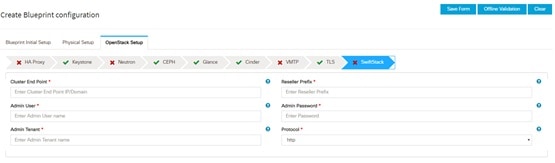
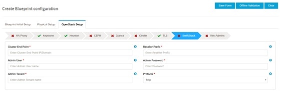
SwiftStack optional section will be visible only if SwiftStack is selected from Blueprint Initial Setup Page. SwiftStack is only supported
with KeyStonev2. If you select Keystonev3, swiftstack will not be available to configure.
|
Following are the options that needs to be filled for SwiftStack:
|
Cluster End Point
|
IP address of PAC (proxy-account-container) endpoint.
|
|
Admin User
|
Admin user for swift to authenticate in keystone.
|
|
Admin Tenant
|
The service tenant corresponding to the Account-Container used by Swiftstack.
|
|
Reseller Prefix
|
Reseller_prefix as configured for Keysone Auth,AuthToken support in Swiftstack E.g KEY_
|
|
Admin Password
|
swiftstack_admin_password
|
|
Protocol
|
http or https
|
|
|
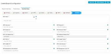
APICINFO tab is available in Openstack setup, when the Tenant type ACI/VLAN is selected in blueprint initial setup.
| Note
|
When ACI/VLAN is selected then ToR switch from initial setup is mandatory.
|
|
|
Name
|
Description
|
|
APIC Hosts field
|
Enter host input. Example: <ip1|host1>:[port] . max of 3, min of 1, not 2;
|
|
apic_username field
|
Enter a string format.
|
|
apic_password filed
|
Enter Password.
|
|
apic_system_id field
|
Enter input as string. Max length 8.
|
|
apic_resource_prefix field
|
Enter string max length 6.
|
|
apic_tep_address_ pool field
|
Allowed only 10.0.0.0/16
|
|
multiclass_address_pool field
|
Allowed only 225.0.0.0/15
|
|
apic_pod_id field
|
Enter integer(1- 65535)
|
| apic_installer_tenant field
|
Enter String, max length 32
|
|
apic_installer_vrf field
|
Enter String, max length 32
|
|
api_l3out_network field
|
Enter String, max length 32
|
|
|
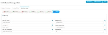
VTS tab is available in Openstack setup, when Tenant Type is VTS/VLAN selected.
If vts day0 is enabled then SSH username and SSH password is mandatory.
If SSH_username is input present then SSH password is mandatory vice-versa
|
|
Name
|
Description
|
|
VTS Day0 (checkbox)
|
True or false default is false.
|
|
VTS User name
|
Enter as string does not contain special characters.
|
|
VTS Password
|
Enter password
|
|
VTS NCS IP
|
Enter IP Address format.
|
|
VTC SSH Username
|
Enter a string
|
|
VTC SHH Password
|
Enter password
|
|
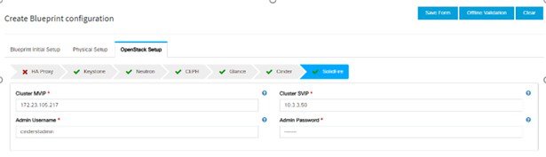
-
For SolidFire, enter the following:
|
Name
|
Description
|
|
SolidFire is visible for configuration on day0
SolidFire is not allowed as a day-2 deployment option
SolidFire is always available with CEPH.
|
 |
|
Cluster MVIP field
|
Management IP of SolidFire cluster.
|
|
Cluster SVIP field
|
Storage VIP of SolidFire cluster.
|
|
Admin Username
|
Admin user on SolidFire cluster
|
|
Admin Password
|
Admin password on SolidFire cluster.
|
|
|
-
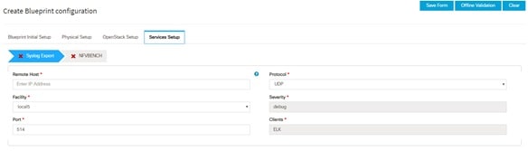
If Syslog Export or NFVBENCH is selected in Blueprint Initial Setup Page, then Services Setup page will be enabled for user to view. Following are the options under Services Setup Tab:
|
Name
|
Description
|
|
Syslog Export
|
Following are the options for Syslog Settings:
User can add maximum of three entries.
To add new SysLog information, click on Add SysLog button, fill all the required information listed below and hit Save button. 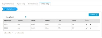
|
Remote Host
|
Enter Syslog IP address.
|
|
Protocol
|
Only UDP is supported.
|
|
Facility
|
Defaults to local5.
|
|
Severity
|
Defaults to debug.
|
|
Clients
|
Defaults to ELK.
|
|
Port
|
Defaults to 514 but can be modified by the User.
|
|
|
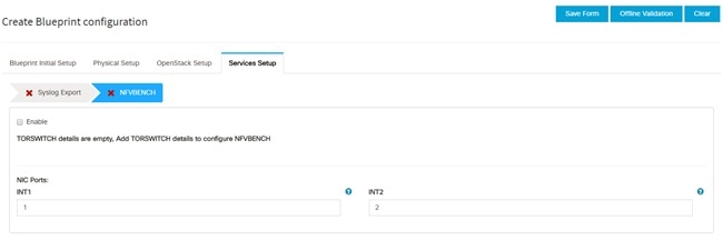
NFVBENCH
|
NFVBENCH enable checkbox by default isfalse.
Add ToR information connect to Switch: 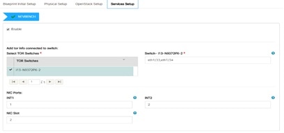
-
Select a TOR Switch and enter the Switch name.
-
Enter the port number. For example, eth1/5 . VTEP VLANS (mandatory and needed only for VTS/VXLAN). Enter two different VLANs
for VLAN1 and VLAN2.
-
NIC Ports: INT1 and INT2 optional input. Enter the two port numbers of the 4-port 10G Intel NIC at the management node used
for NFVBench.
NIC Slot: Optional input, indicates which NIC to use in case there are multiple NICs.
| Note
|
NIC port and slot need to be together.
|
|
|
ENABLE_ESC_PRIV
|
Enable the checkbox to set it as True. By default it is False.
|
|


 Feedback