The documentation set for this product strives to use bias-free language. For the purposes of this documentation set, bias-free is defined as language that does not imply discrimination based on age, disability, gender, racial identity, ethnic identity, sexual orientation, socioeconomic status, and intersectionality. Exceptions may be present in the documentation due to language that is hardcoded in the user interfaces of the product software, language used based on RFP documentation, or language that is used by a referenced third-party product. Learn more about how Cisco is using Inclusive Language.
The following topics tell you how to configure and install Cisco VIM:
Cisco VIM
Installation Overview
Before you can install Cisco Virtual Infrastructure Manager, complete the procedures in Preparing for Cisco NFVI Installation. If your management node does not have Internet access, complete the Preparing to Install Cisco NFVI on Management Nodes Without Internet Access procedure. The Cisco VIM installation procedure provides two methods for downloading and installing the Cisco VIM installation
files, from USB stick prepared for installation, or from the Internet.
Completing these
procedures ensures the Cisco NFVI network infrastructure is set up before the
Cisco VIM installation. The bootstrap script is then kicked off, which
downloads installer repository, installs Docker and dependencies and starts
installer web service,
The Cisco VIM installer can then be launched. It validates the testbed configuration file (setup_data.yaml), creates new vNICs
on the controller, compute, and dedicated storage nodes based on the configuration provided in the setup_data.yaml file. This
is followed by the Pxeboot Execution Environment (PXE) boot of RHEL onto the target nodes (control, compute and storage) through
the Cobbler server set up on the management node. After the installation, the Cisco VIM installer performs common steps across
all the Cisco NFVI nodes.
Next, Ceph related
packages required for managing the cluster and creating OSD and monitor nodes
are installed on the control and storage nodes. By default, the minimum three
Ceph monitor nodes are installed at the host level on the control nodes. These
serve as management nodes and have the administration keyring. Ceph
configurations, such as ceph.conf and Ceph client keyrings files, are stored
under /etc/ceph on each controller. Each Ceph storage node associates an Object
Storage Daemon (OSD) to a physical hard drive with a write journal on a
separate SSD to support small block random I/O.
The following
illustration provides an overview to the Cisco VIM installation.
Figure 1. Cisco VIM
Installation Flow
If you have Cisco Unified Management, complete only part of the Cisco VIM installation procedure and proceed to the Installing Cisco VIM Insight on page procedure followed by Installing Cisco VIM through Cisco VIM Unified Management to complete the configuration and setup of Cisco VIM using the Cisco VIM Insight. If you do not have Cisco VIM UM, configure
Cisco VIM by editing the data_setup.yaml as described in the Cisco VIM installation.
Installing Cisco
VIM
This procedure allows you to install the Cisco VIM on a Cisco NFVI management node:
Before you begin
You need to get Cisco NFVI installation file download site credentials from your Cisco account representative.
The private networks 192.168.1.0/24 and 192.168.2.0/24 are internally reserved for testing the cloud from a control and data
plane point of view. Cisco recommends that you do not use these reserved networks while preparing network layouts.
You need to provide a valid certificate signed by a trusted certificate authority, for the Cisco VIM deployment. It needs
to be a server certificate with a common name matching the IP address and DNS name specified in the setup data file under
"external_lb_vip_address" and "external_lb_vip_fqdn". To ensure security, use only the valid certificate signed by a trusted
certificate authority in a production environment. For details on generating self-signed certificate, see Setting Up Cisco VIM OpenStack Configurations
Procedure
Step 1
If your management node does not have Internet access, use the prepared USB stick and complete the following steps:
Insert the USB stick into the management node drive.
Run the import_artifacts.sh script to copy all artifacts onto the management node, for example:
cd ~/installer-<tag_id>/tools
./import_artifacts.sh
All the installation artifacts are copied to /var/cisco/artifacts/ on the management node
If you are not
installing Cisco VIM Insight, complete the following steps.
Step 3
Change to the
installer directory by running the following command:
cd ~/installer-<tag_id>
Step 4
Create a dir (for example, ~/Save/) to contain a copy of the setup_data.yaml file, the file that configures the Cisco NFVI
for your particular implementation.
Step 5
Change to the
openstack-configs directory and copy the example Cisco VIM setup_data.yaml file
into the directory you just created:
cd openstack-configs/
cp setup_data.yaml.<C_or_B>_Series_EXAMPLE setup_data.yaml
~/Save/setup_data.yaml
Note
Only the CPU and MEM allocation ratio needs to be changed for the target pod. Update the following to your target value:
NOVA_RAM_ALLOCATION_RATIO: 1.5 # range of 1.0 to 4.0
NOVA_CPU_ALLOCATION_RATIO: 16.0 # range of 1.0 to 16.0
Step 6
With a yaml editor, modify the copied example setup_data.yaml file as the data setup file for your implementation. This includes
both Cisco NFVI data and OpenStack parameters.
After the
installation is complete, you can view the installation logs at
/var/log/mercury.
Cisco VIM Client
Details
Cisco VIM combines the CLI and API so that you can use the CLI or API installer transparently.
Note
For a complete list of Cisco VIM REST API commands, see the Cisco NFVI Administrator Guide.
Before you use the Cisco VIM CLI, check that the API server is up and pointing to the right installer directory. You can execute
the following command to validate the state of the API server and the installer directory it is referencing:
# cd installer-<tagid>/tools
#./restapi.py -a status
Status of the REST API Server:  active (running) since Thu 2016-08-18 09:15:39 UTC; 9h ago
REST API launch directory: /root/installer-<tagid>/
Verify the server status is active and the restapi launch directory is the same the directory from where the installation
is launched. If the installer directory, or the REST API state is not correct, go to the target installer directory and execute
the following:
# cd new-installer-<tagid>/tools
#./restapi.py -a setup

Check if the REST API server is running from the correct target directory
#./restapi.py -a status
Status of the REST API Server:  active (running) since Thu 2016-08-18 09:15:39 UTC; 9h ago
REST API launch directory: /root/new-installer-<tagid>/
The REST API tool also provides the options to restart, tear down and reset password for the REST API server as listed:
# ./restapi.py -–h

usage: restapi.py [-h] --action ACTION [--yes] [--verbose]

REST API setup helper

optional arguments:
  -h, --help            show this help message and exit
  --action ACTION, -a ACTION
                        setup - Install and Start the REST API server.
                        teardown - Stop and Uninstall the REST API server.
                        restart - Restart the REST API server.
                        regenerate-password - Regenerate the password for REST API server.
                        reconfigure-tls - Reconfigure SSL certificates and key.
                        upgrade - Upgrade to new workspace.
                        reset-password - Reset the REST API password with user given
password.
                        status - Check the status of the REST API server.
  --yes, -y             Skip the dialog. Yes to the action.
  --verbose, -v         Perform the action in verbose mode.
If the REST API server is not running, executing ciscovim shows the following error message:
# ciscovim –setupfile ~/Save/<setup_data.yaml> run
If the installer directory, or the REST API state is not correct or it is pointing to an incorrect REST API launch directory,
go to the installer-<tagid>/tools dir and execute:
# ./restapi.py -–action setup
To confirm that the Rest API server state and launch directory is correct, execute:
# ./restapi.py -–action status
If you ran the REST API recovery step on an existing pod, run the following command to ensure that the REST API server continues
to manage the existing pod:
For an overview to the commands you can execute from the CLI, enter the following command:
 ciscovim --help
usage: ciscovim [--setupfile <setupdata_file>] <subcommand> ...

Command-line interface to the Cisco Virtualized manager

Positional arguments:
  <subcommand>
    run                         Perform/terminate an install operation
    install-status              Status of installation of the Openstack cloud
    list-steps                  List steps
    add-computes                Add compute-nodes to the Openstack cloud
    add-storage                 Add a storage-node to the Openstack cloud
    list-nodes                  List the nodes in the Openstack cloud
    remove-computes             Remove compute-nodes from the Openstack cloud
    remove-storage              Remove a storage-node from the Openstack cloud
    replace-controller          Replace a controller in the Openstack cloud
    list-openstack-configs      List of Openstack configs that can be changed
                                using reconfigure
    list-password-keys          List of password keys that can be changed
                                using reconfigure
    reconfigure                 Reconfigure the Openstack cloud
    cluster-recovery            Recover the Openstack cluster after a network
                                partition or power outage
    mgmtnode-health             Show health of the Management node
    commit                      Commit an update
    rollback                    Rollback an update
    update                      Update the Openstack cloud
    update-status               Status of the update operation
    upgrade                     Upgrade the Openstack cloud
    check-fernet-keys           Check whether the fernet keys are successfully
                                synchronized across keystone nodes
    nfvbench                    Launch NFVBench Flows
    nfvimon                     NFVI Monitoring / Zenoss management operations
    period-rotate-fernet-keys   Set the frequency of fernet keys rotation on
                                keystone
    resync-fernet-keys          Resynchronize the fernet keys across all the
                                keystone nodes
    rotate-fernet-keys          Trigger rotation of the fernet keys on
                                keystone
    client-version              Show Virtualized Infrastructure Manager
                                Version
    version                     Show Virtualized Infrastructure Manager
                                Version
    help                        Display help about this program or one of its
                                subcommands.

Optional arguments:
  --setupfile <setupdata_file>

See "ciscovim help COMMAND" for help on a specific command.


To look at the help for a sub-command (e.g. run) execute the following:
# ciscovim help run
usage: ciscovim run [--join] [--perform <perform>] [--skip <skip>] [-y] Perform a install operation
Optional arguments:
--join	Join the installation process
--perform <perform> Perform the following steps.
--skip <skip>	Skip the following steps.
-y, --yes	Yes option to skip steps without prompt [root@MercRegTB1 installer]#
You can also run the installer in multiple smaller steps. To understand the steps involved during installation
execute the following command:
# ciscovim list-steps
Virtualized Infrastructure Manager:
===================================
+-------------------------+--------------+
| Operations              | Operation ID |
+-------------------------+--------------+
| INPUT_VALIDATION        |      1       |
| MGMTNODE_ORCHESTRATION  |      2       |
| VALIDATION              |      3       |
| BAREMETAL               |      4       |
| COMMONSETUP             |      5       |
| CEPH                    |      6       |
| ORCHESTRATION           |      7       |
| VMTP                    |      8       |
+-------------------------+--------------+
To execute the installer in steps, include specific steps from above. For example:
$ ciscovim run --perform 1,3 –y
Similarly, you can execute the installation using the skip option, where you explicitly indicate which options to skip. For
example
$ ciscovim run --skip 1,3 –y
Note
When using the step-by-step installation, keep a track of what steps are already completed, or unpredictable results might
occur.
While the install time varies from pod to pod, typical installation times through the Internet for a UCS C-series with three
controller, nine compute, and three storage are listed in the following table.
Table 1.
Operation ID
Operation
Estimated Time
1
Input validation
6 minutes
2
Management node orchestration
40 minutes
3
Run time Validation
30 seconds
4
Bare metal
60 minutes
5
Host setup
10 minutes
6
Ceph
5 minutes
7
Orchestration
25 minutes
8
VMTP (external and provider networks)
14 minutes
Cisco VIM
Configuration Overview
The following topics provide a list of Cisco NFVI configurations you must enter in setup_data.yaml with a yaml editor. These
configurations has to be performed prior to running the Cisco VIM installation. If you are installing Cisco Insight, you have
to complete the Cisco VIM data and OpenStack configurations using VIM Insight as described in Installing Cisco VIM through Cisco VIM Unified Management .
Configuring ToR
Automatically
Cisco VIM, provides a complete automation of the cloud deployment. Cisco VIM, of this feature is to automate day-0 configuration
of N9xxx series Top of Rack(ToR) switches. The feature is optional and only applies to Pods that are running without ACI.
For ToR switch details related to ACI, refer to the section, Enabling ACI in Cisco VIM . Purpose is to automate Power-On Auto Provisioning (post-POAP) configuration on ToR offering of Cisco VIM, constitutes of
one or more pair of identical Cisco N9300 series switches. The day-0 ToR automation configures the interfaces that are connected
to the management (br_mgmt), control, compute, and storage nodes of the pod. In addition, it configures the VPC peer link
interfaces for ToR pairs. The automation handles both B and C-series pods. The automation includes configuration of the edge
ports in the leaf switches off which the hosts hang-out and the VPC peer link between the switches. Auto-Configuration feature
does not include the configuration of the spine switches, and the connectivity between the leaf and the spine; that is the
upstream link of the spine switches that carry the external VLAN connectivity.
As the feature is a post-POAP automation provisioning, the management interface, vrf, and admin user have to be pre-provisioned
on each of the ToR switch. Also, ssh has to be enabled in each ToRs. The recommended N9K switch software versions are 7.0(3)I4(6)
and 7.0(3)I6(1). Bootstraping the ToR image is still a manual process. Installer API interface (br_api) on the management
node have to be up and running, and the ssh to the management node through SSH must be working. You can access each of the
ToRs through its management interface from the Cisco VIM management node using SSH.
Setting Up the Cisco
VIM Data Configurations
The Cisco VIM configuration file, setup_data.yaml, installs and configures the VIM deployment. When creating this file, take
extreme care. Any change to this configuration after deployment, with the exception (example: NFVIMON, of adding and removing
nodes and so on) causes a stack redeployment. Pay particular attention to the pod networking layout plan configured in setup_data.yaml
because any future changes to it requires the pod to be reinstalled.
If your configurations are correct, the installation goes smoothly. Cisco recommends using a YAML editor on Linux (PyCharm,
Komodo or vi/vim with YAML plugin) to edit this file. Items shown in brown must be changed to your specific testbed. Do not
copy the examples shown below into your YAML file, because your browser might render the characters differently. If you are
using the Cisco VIM installer, you cannot update the OpenStack config files (for example, ml2_conf.ini, and other files) directly.
All OpenStack configurations must be in the setup_data.yaml file. This ensures that the installer has a view of the OpenStack
deployment, so that it can reliably perform later software updates and upgrades. This ensures a consistent and repeatable
installation, which is important. Key setup file parts are shown in the following sections.
Setting Up the ToR
Configurations for B-series and C-series
The ToR configuration is driven through the mercury setup_data.yaml configuration. The information for automated TOR configuration
is provided in two parts in the setup_data.yaml file. The common information is in the TORSWITCHINFO section, whereas the
information on individual switch ports connected to specific nodes are under SERVERS section for C-seires, and UCSM-COMMON
section for B-series. If the TORSWITCHINFO section is not provided or CONFIGURE_TORS attribute under TORSWITCHINFO then all
the ToR provisioning related steps are skipped. The ToR section contains attributes related to ToR connection, configuration
for the management interface for the management node, and vPC peer details in case of ToR pairs.
Note
The port-channel
number for the vPC peer link interfaces, is derived from the Vpc domain. The
ToRs are paired with each other based on their corresponding vpc_peer_link
addresses.
The attributes for vpc peer vlan info, vpc domain and br_mgmt_po_info have to match across the ToRs, and should only be defined
in only two of the TORs, where the management node is hanging off. The attribute for vpc_peer_vlan_info is optional. If it
is not specified, it derives a list of VLAN ids from the host/FI facing interfaces and br_mgmt interface. Also, the attribute
for ssn_num which represents the chassis serial number is optional.
The chassis serial
number can be obtained by executing the following command on each of the ToRs:
show license host-id
In the case of
B-series, Cisco VIM configures the UCSMCOMMON section to declare the interface
configuration under
tor_info_fi
and
tor_info_fi_redundant
for the FI.
Note
ToR names need to
match with names provided in the TORSWITCHINFO section.
In this example of
B-Series, tor_info is not declared in the SERVERES section as all connectivity
is through the FI (controller, compute, and storage) declared in the UCSCOMMON
section. VLANs for the FI facing interfaces are derived from the NETWORK
segment ROLES for controller, compute, and storage nodes.
The SERVERS section
declares the interface configurations for each of the controller, compute, and
storage nodes under
tor_info.
VLANS for host facing
interfaces are derived from NETWORK section based on the server ROLES
definition of each of the servers and their corresponding network profile roles
assigned for each of the segments.
Server Level
Setup_data info for C-series with Intel NIC
When the C-series pod
is configured to run in a complete Intel NIC environment, the ToR have an
additional configuration that is dp_tor_info section. Control plane and data
plane traffic are broken out into two separate interfaces with VLAN limiting
applied on each of the interfaces facing the controller and compute nodes.
Server Level
Setup_data info for C-series with Intel NIC with SRIOV
When the C-series pod
is configured to support SRIOV with Intel NIC, a third interface is configured
to allow SRIOV traffic for the compute nodes. Switchports configured for SRIOV
are not placed in a port-channel. VLAN limiting is applied to this interface
for all the data plane related VLAN IDs.
Custom Configuration
is an optional procedure. The setup_data.yaml file has a section called
CUSTOM_CONFIG to support custom configuration. Under the CUSTOM_CONFIG section,
raw CLI commands can be provided at the global, port channel, and switchport
level. CUSTOM_CONFIG is applied at the time of bootstrap and add-interfaces
workflow steps.
For example:
setup_data.yaml
TORSWITCHINFO:
  CONFIGURE_TORS: true
  CUSTOM_CONFIG:
    GLOBAL:
      [<’cli line 1’>,
       <’cli line 2’>,]
    PORTCHANNEL:
      [<’cli line 1’>]
    SWITCHPORT:
      [<’cli line 1’>,
       <’cli line 2’>,]
Setting Up ToR
Configurations for NCS-5500
Note
In Cisco VIM 2.4, the following caveats apply to a Cisco VIM deployment with NCS:
BGP: For a fresh install of Cisco VIM, assure no BGP configuration is present on the NCS, otherwise the peering between the
two NCS does not come up properly. Un-configure any existing BGP configuration. If additional BGP complimentary configuration
is needed, add it after a successful Cisco VIM install.
Segment-Routing: The global block of Segment Routing IDs have to be pre-defined by the admin. Make sure that the prefix defined
within the setup_data.yaml is within the Segment Routing global block range.
NCS Interface Naming: There are a set of different Interface naming variations. We support the following: [Te0/0/0/0, TenGigE0/0/0/0,
Gi0/0/0/0, Hu0/0/1/0, HundredGigE 0/0/1/0, FortyGigE0/0/0/0].
Any manual adjustments to the ISIS, L2VPN sections (on top of the configuration provided by the CVIM automation) causes subsequent
Cisco VIM installs to fail.
For a Cisco VIM with NCS-5500 Auto-ToR is a must-have. You can use the Auto-ToR configuration feature to setup NCS-5500.
The mercury Cisco VIM setup_data.yaml configuration file is used as an input file for the configuration.
The
setup_data.yaml file contains the following three sections:
TORSWITCHINFO: This
section provides the general information.
SERVERS section for
C-series: This section provides the information on the switch ports that
are connected to the specific nodes. When the micro pod is configured to run in
a complete Intel NIC environment with NCS-5500 as the ToR, the SERVER level
configurations include tor_info (for control plane) and dp_tor_info (data
plane) section. Control plane and data plane traffic are broken out into two
separate interfaces with bridge domains applied on each of the control and data
interfaces facing each for the controller and compute nodes.
MULTI_SEGMENT_ROUTING_INFO: This section provides the information related
to routing.
NCS-5500
supports a micro-pod with additional computes running on Intel 710 NICs with no
SR-IOV with mechanism driver of VPP.
Note
The current release supports the use of two NCS-5500 within a single pod.
The following snippet shows an example of the mercury setup_data.yaml configuration file for NCS-5500
TORSWITCHINFO:
  CONFIGURE_TORS: true		# Mandatory
  TOR_TYPE: NCS-5500			# Mandatory

  SWITCHDETAILS:
    -
      hostname: <NCS-5500-1>		# hostname of NCS-5500-1
      username: admin
      password: <ssh_password of NCS-5500-1>
      ssh_ip: <ssh_ip_address of NCS-5500-1>
      vpc_peer_keepalive: <ssh IP address of the peer NCS-5500-2>
      br_mgmt_port_info: <interface of which br_mgmt of management node is hanging of NCS-5500-1>
      br_mgmt_po_info: <int; bundle Ethernet interface to pxe the management node>
      vpc_peer_port_info: <local interface to which peer NCS-5500 is connected, “,” separated, max of 2 entries>’ >
      vpc_peer_port_address:  <local address with mask for vpc_peer_port_info, “,” separated, max of 2 entries>’ >
      isis_loopback_addr: <local isis loopback interface address without mask> # assumes /32
      isis_net_entity_title: <isis network_entity_title>
      isis_prefix_sid: <int between 16000-1048575>	# has to be unique in the ISIS domain and depends on the
 global segment routing block define by the admin
    -
      hostname: <NCS-5500-2>		# hostname of NCS-5500-2
      username: admin
      password: <ssh_password of NCS-5500-2>
      ssh_ip: <ssh_ip_address of NCS-5500-2>
      vpc_peer_keepalive: <ssh IP address of the peer NCS-5500-1>
      br_mgmt_port_info: <interface of which br_mgmt of management node is hanging of NCS-5500-2>
      br_mgmt_po_info: <int; bundle Ethernet interface to pxe the management node>
      vpc_peer_port_info: <local interface to which peer NCS-5500 is connected>,"," seperated, max of two entries
      vpc_peer_port_address:  <local address with mask for vpc_peer_port_info>,"," seperated, max of two entries
      isis_loopback_addr: <local isis loopback interface address without mask> # assumes /32
      isis_net_entity_title: <isis network_entity_title>
      isis_prefix_sid: <int between 16000-1048575> has to be unique in the ISIS domain and depends on the global segment routing block define by the admin.	# has to be unique in the ISIS domain
      splitter_opt_4_10: 'FortyGigE<C/D/X/Y>,HundredGigE<E/F/A/B>' # Optional for NCS-5500, only when splitter is needed on per switch basis (that is, the peer switch may or maynot have the entry)

SERVER SECTION FOR C SERIES:
      a27-fretta-micro-1:
 					cimc_info: {cimc_ip: 172.28.121.172}
 					dp_tor_info: {NCS-5500-1: TenGigE0/0/0/1, NCS-5500-2: TenGigE0/0/0/1, po: 1}
 					hardware_info: {VIC_slot: MLOM}
 					rack_info: {rack_id: RackA}
 					tor_info: {NCS-5500-1: TenGigE0/0/0/0, NCS-5500-2: TenGigE0/0/0/0, po: 2}
# Optional
sriov_tor_info: {NCS-5500-1: TenGigE0/0/0/6, NCS-5500-2: TenGigE0/0/0/6} or
sriov_tor_info: {NCS-5500-1: ‘TenGigE0/0/0/6, TenGigE0/0/0/7’, NCS-5500-2: ‘TenGigE0/0/0/6, TenGigE0/0/0/7’}

 					a27-fretta-micro-2:
 					cimc_info: {cimc_ip: 172.28.121.174}
 					dp_tor_info: {NCS-5500-1: TenGigE0/0/0/3, NCS-5500-2: TenGigE0/0/0/3, po: 3}
 					hardware_info: {VIC_slot: MLOM}
 					rack_info: {rack_id: RackB}
 					tor_info: {NCS-5500-1: TenGigE0/0/0/2, NCS-5500-2: TenGigE0/0/0/2, po: 4}

 					a27-fretta-micro-3:
 					cimc_info: {cimc_ip: 172.28.121.175}
 					dp_tor_info: {NCS-5500-1: TenGigE0/0/0/5, NCS-5500-2: TenGigE0/0/0/5, po: 5}
 					hardware_info: {VIC_slot: MLOM}
 					rack_info: {rack_id: RackC}
# optional
sriov_tor_info: {NCS-5500-1: ‘TenGigE0/0/0/8, TenGigE0/0/0/9’, NCS-5500-2: ‘TenGigE0/0/0/8, TenGigE0/0/0/9’}

#Note: if sriov is defined, it need not be present on all servers; However, when present
on a given server, the number of SRIOV port need to be 4 and consistent across the servers; Also, please set the INTEL_SRIOV_PHYS_PORTS to 4, when using SRIOV with NCS-5500 as ToR.
Please set the value of INTEL_SRIOV_VFS as per the settings of your VNF (see details later for the default values, etc)

tor_info: {NCS-5500-1: TenGigE0/0/0/4, NCS-5500-2: TenGigE0/0/0/4, po: 6}


MULTI_SEGMENT_ROUTING_INFO:
      bgp_as_num: <1 to 65535>
      isis_area_tag: <string>
      loopback_name: <loopback<0-2147483647>>
      api_bundle_id: <1 to 65535>
      api_bridge_domain: <string> #Optional, only needed when br_api of mgmt node is also going via NCS-5500; #this item and api_bundle_id are mutually exclusive
      ext_bridge_domain: <string> # user pre-provisions physical, bundle interface, subinterface and external BD” for external uplink and provides
external BD info in the setup_data
NCS Day-0 Configuration (Prior to starting Cisco VIM install)
The following snippets have to be defined on the NCS before starting Cisco VIM installation:
SSH:
ssh server v2
ssh server vrf default
ssh server netconf port 831
ssh server netconf vrf default
ssh timeout 60
ssh server rate-limit 600

USERNAME:
username admin
 group root-lr
 group cisco-support
 secret 0 <password>
Note
For SSH to work generate a key using crypto key generate rsa.
Pre-requisites for Segment Routing Global Block and ISIS Prefix
The segment routing configuration has to be predefined by the admin.
The following snippet provides an example:
segment-routing
 global-block 16000 20000

The prefix within the ISIS setup_data.yaml configuration has to be within the global-block IDs. Example:

TORSWITCHINFO:
  CONFIGURE_TORS: true
  SWITCHDETAILS:
  - {br_mgmt_po_info: 1, br_mgmt_port_info: TenGigE0/0/0/10, hostname: a25-ncs5500-1-ru30,
    isis_loopback_addr: 10.10.10.10, isis_net_entity_title: 49.0001.1720.1625.5011.00,
    isis_prefix_sid: 16001, password: CTO1234!, ssh_ip: 172.28.123.176, username: admin,
    vpc_peer_keepalive: 172.28.123.177, vpc_peer_port_address:
'100.100.100.2/29,100.100.101.2/29',
    vpc_peer_port_info: 'HundredGigE0/0/1/4,HundredGigE0/0/1/5'}
  - {br_mgmt_po_info: 1, br_mgmt_port_info: TenGigE0/0/0/10, hostname: a25-ncs5500-2-ru29,
    isis_loopback_addr: 20.20.20.20, isis_net_entity_title: 49.0001.1720.1625.4022.00,
    isis_prefix_sid: 16002, password: CTO1234!, ssh_ip: 172.28.123.177, username: admin,
    vpc_peer_keepalive: 172.28.123.176, vpc_peer_port_address: '100.100.100.3/29,100.100.101.3/29',
    vpc_peer_port_info: 'HundredGigE0/0/1/2,HundredGigE0/0/1/3'}
  TOR_TYPE: NCS-5500
Pre-requisites for API and External Network Segments with NCS-5500 as TOR
Pre- Provision the NCS-5500 with the Bridge domains for API and External network segments.The configured bridge domain names
for api and external need to be the same as those defined in setup_data.yaml (api_bridge_domain and ext_bridge_domain) under
the MULTI_SEGMENT_ROUTING_INFO section defined above.
A check on each of the NCS-5500 should show the following:
RP/0/RP0/CPU0:NCS-5500-2#sh run l2vpn bridge group cvim
  l2vpn
bridge group cvim
    bridge-domain api
l2vpn
  bridge group cvim
    bridge-domain external
During the deployment of NCS-5500 as TOR, we also support the workloads off the provider network along with the tenant network.
Listed below are some of the assumptions under which this combination works.
Provider network segment has to be in scope from day-0. Few of the PROVIDER_VLAN_RANGES has to be defined.
You can always expand the PROVIDER_VLAN_RANGES with additional VLAN range (minimum starting VLAN range is 2)
The maximum number of PROVIDER_VLAN_RANGES and TENANT_VLAN_RANGES should add up to 200.
Bridge domain for provider starts with prefix: provider VLANId. They are created manually on the NCS-5500, before the VIM
deployment begins; and upstream interfaces are stitched in.
Support and pre-requisites for Provider Network with NCS-Concept
In a deployment of NCS-5500 as TOR, along with the tenant network, we also support provider networks. The following points
are key to use provider_networks with a NCS TOR:
Provider network segment has to be defined on day-0; also, a handful of PROVIDER_VLAN_RANGES has to be defined in the setup_data.yaml.
Note
You cannot add it after a Cisco VIM deployment!
The PROVIDER_VLAN_RANGES can be extended after a Cisco VIM install by running reconfigure with a updated setup_data.yaml (min
starting VLAN range is 2, for example PROVIDER_VLAN_RANGES: 3200:3202 (existing range),3204:3206 (newly added range))
The maximum number of PROVIDER_VLAN_RANGES and TENANT_VLAN_RANGES should not exceed 200.
Bridge domain for provider starts with prefix: provider<VLANId> and are created manually on the NCS-5500 before VIM deployment
begins with necessary upstream interfaces configured accordingly.
Pre-requisites for Provider Network with NCS-5500 as TOR
Provider network support requires the following pre-requisites:
Procedure
Step 1
Define the network and provider vlan ranges sections in setup_data.yaml.
Pre-provisioning the NCS with bridge-domains for corresponding VLANs and plumbing the uplink configuration into these bridge-domains.
RP/0/RP0/CPU0:NCS-5500-2#sh run l2vpn bridge group cvim
l2vpn
  bridge group cvim
    bridge-domain provider127

l2vpn
  bridge group cvim
    bridge-domain provider3406

l2vpn
  bridge group cvim
    bridge-domain provider3407
Note
The Cisco VIM Automation will then configure all the host facing subinterfaces for these provider vlans, EVIs and plumb them
into each of the pre-provisioned provider bridge-domains.
Note
When pre-provisioning bridge-domain, ensure that the BD names follow the naming convention of "provider<vlan-id>".
Installing Cisco VIM with NCS-5500 as TOR
Note
Cisco VIM does not support Jumbo Frame with NCS-5500; so plan your deployment without it in place.
Note
Currently there is an Intel X710 issue with the i40e driver version 1.6.27-k shipped with RHEL7.4, intermittent traffic drop/not
forward on one of the bonding member interface. This problem becomes more apparent when the same traffic flow conversation
is asymmetrically forwarded, that is the same traffic flow conversation transmitting on bond member 1 and receiving back on
bond member 2. It goes away when the driver is upgraded to the latest official Intel driver version 2.3.6:
The official Intel i40e version 2.3.6 is compiled at the time of the mercury’s hotfix repo build. This takes care of the step
4 baremetal install of all the Controller, Storage, and Compute nodes except Management node. So we recommend you to do step
wise installation to incorporate the changes made into the management node.
Following are the steps to install Cisco VIM:
Procedure
Step 1
Deploy the Management node with the corresponding matching 2.2.x ISO
Step 2
Execute the step1 and step 2
ciscovim --setupfile <setup_data_path> run --perform step 1,2
ciscovim --setupfile <setup_data_path> run --perform 3,4,5…
Intel NIC
Support
Cisco VIM supports C-series pod running with either all Intel 710X NICs or Cisco VICs for control and data plane. In the
Intel NIC setup, M4 and M5 (Micropod) based pods need to have 2-4 port and 1 or 2 4 port X710 respectively, for control and
data plane connectivity. The orchestrator identifies the NIC support based on the following INTEL_NIC_SUPPORT values:
False-This is the default value. The orchestrator assumes that all the servers have Cisco VIC
True-The orchestrator assumes that all the servers have Intel NIC.
To define the value, run the following command
# INTEL_NIC_SUPPORT: <True or False>
The X710 based NIC redundancy is enabled by default for M4-based Intel NIC system, but not for M5-based Intel NIC system.
See Figure 7: UCS C-Series Intel NIC Details in UCS C-Series Network Topologies. To bring in NIC redundancy across the X710s for M5-based Intel NIC systems, define the following global parameter in the
setup_data.
# NIC_LEVEL_REDUNDANCY: <True or False> # optional and only applies when INTEL_NIC_SUPPORT is set to True
A C-series pod, running Intel NIC, also supports SRIOV as an option when defined in a setup_data. To enable SRIOV as an option,
define a value in the range 1-32 (32 is maximum number of INTEL_SRIOV_VFS: <integer>.
By default, in the C-series pod running with 4 port Intel 710 card, 1 port (port #c) from each of the Intel NICs are used
for SRIOV. However, some VNFs needs additional SRIOV ports to function. To meet the requirement, an additional variable has
been introduced in the setup_data.yaml file by which you can include a second port (port d) of the Intel NIC for SRIOV.
To adjust the number of SRIOV ports, set the following option in the setup_data.yaml file:
#INTEL_SRIOV_PHYS_PORTS: <2 or 4>
The parameter, INTEL_SRIOV_PHYS_PORTS is optional, and if nothing is defined a value of 2 is used. The only values the parameter
takes is 2 or 4. For NCS-5500, the only value supported for INTEL_SRIOV_PHYS_PORTS is 4, and has to be defined for SRIOV support
on NCS-5500. As the M5 Micropod environment is based on X710 for control and data plane and an additional XL710 or 2 port
X710 for SRIOV only INTEL_SRIOV_PHYS_PORTS of 2 is supported.
SRIOV support on a Cisco VIC POD
Cisco VIM supports M4 based C-series pod running with one 2-port Cisco VIC for control plane and two 2-port Intel 520s or
two 2-port XL710 for SRIOV (called VIC/NIC deployment). We also support M5 based C-series pod running with one 2-port Cisco
VIC for control plane and two 2-port XL710 for SRIOV.
The orchestrator identifies the VIC/NIC support based on the following CISCO_VIC_INTEL_SRIOV values:
False-This is the default value. The orchestrator assumes that all the servers have Cisco VIC.
True-The orchestrator assumes that all the servers have Intel NIC.
To define the value, run the following command:
# CISCO_VIC_INTEL_SRIOV: <True or False>
A C-series M4 pod, running Cisco VIC/Intel NIC (2x520 or 2xXL710), also supports SRIOV on the Intel NIC. To enable,SRIOV define
a value in the range 1-63 (63 is maximum) (for X520) or 1-32 (32 is maximum for XL710) number of INTEL_SRIOV_VFS: <integer>
By default in the C-series M4 pod running with Cisco VIC and Intel 520/XL710, the control plane runs on the Cisco VIC ports,
and all the 4 ports from the 2 Intel 520 NICs or 2 intel XL710 are used for SRIOV. C-Series M5 pods, runs with Cisco VIC and
Intel XL710, the control plane runs on the Cisco VIC ports, and all the 4 ports from the 2 intel XL710 are used for SRIOV.
In the pods running with CISCO_VIC_INTEL_SRIOV option, some computes can run only with Cisco VIC without SRIOV option present
on it if they do not have Intel NIC cards in them.
Define the following parameter in the setup_data yaml to setup the card type, in SRIOV (only for M4 based pod).
#SRIOV_CARD_TYPE: <X520 or XL710>
Note
There are different card types present in the compute. If SRIOV_CARD_TYPE is not provided, CVIM chooses the first 2 slots
from all SRIOV compute nodes, and ensures that they are consistent in card type across the cluster. If they are found to be
different, the installation fails. If SRIOV_CARD_TYPE is provided, CVIM chooses the first 2 slots matching the target card
type, from each of the SRIOV compute nodes, and ensures there is a match between intent and reality.
Support of Third Party Compute in Hybrid Mode (HP DL360 Gen9)
Cisco VIM 2.4.x introduces the first third-party compute. The first SKU chosen is HPE ProLiant DL360 Gen9. With this support
we were able to clearly demonstrate that the CVIM software is flexible enough to be enhanced to accommodate for other SKUs.
In CVIM 2.4, the supported deployment is a full-on pod, with OVS as the mechanism driver, where the management, control, and
storage nodes are based on existing Cisco UCS c220/240M4 BOM, and the compute nodes are on HPE ProLiant DL360 Gen9 hardware.
To minimize the changes to the existing orchestration workflow and Insight UI, we adopted to reuse the existing Cisco VIC+NIC
combo deployment scenario which minimize the changes needed for the hardware topology and the "setup_data.yaml" configuration
file. Refer to the above section "Intel NIC Support for SRIOV only", on the NIC settings that need to be passed. to enable
HPE ProLiant DL360 Gen9 third-party compute.
The following table shows the port type mapping between Cisco UCS C-Series compute and HPE ProLiant DL360 compute:
Port Type
Cisco UCS c220/c240M4 Compute
HPE ProLiant DL360 Gen9 Compute
Control and Data Plane
MLOM - Cisco UCS VIC 1227
FlexLOM - HP Ethernet 10Gb 2-port 560FLR-SFP+ Adapter
SRIOV
PCIe - Intel X520-DA2 10 Gbps 2 port NIC
PCIe - HP Ethernet 10Gb 2-port 560SFP+ Adapter
SRIOV
PCIe - Intel X520-DA2 10 Gbps 2 port NIC
PCIe - HP Ethernet 10Gb 2-port 560SFP+ Adapter
As this deployment do not support Auto-ToR configuration, the TOR switch needs to have Trunk configuration with native VLAN,
jumbo MTU, and no LACP suspend-individual on the control and data plane switch ports.
Sample Nexus 9k port-channel configuration is as follows:
interface port-channel30
  description compute-server-hp-1 control and data plane
  switchport mode trunk
  switchport trunk native vlan 201
  spanning-tree port type edge trunk
  mtu 9216
  no lacp suspend-individual
  vpc 30
!
interface Ethernet1/30
  description compute-server-hp-1 flexlom port 1
  switchport mode trunk
  switchport trunk native vlan 201
  mtu 9216
  channel-group 30 mode active
Once the physical connection to the top-of-rack switches and the switch ports' configuration have been completed, enable/add
the following additional variables in the VIM's "setup_data.yaml" configuration file:
UCSMCOMMON:
ucsm_username: "admin"
ucsm_password: <"cisco123">
ucsm_ip: <"a.b.c.d">
ucsm_resource_prefix: <"skull"> # max of 6 chars
ENABLE_UCSM_PLUGIN: <True> #optional; if True, Cisco-UCSM is used, if not defined, default is False
MRAID_CARD: <True or False>
ENABLE_QOS_POLICY: True or False # only allowed if ENABLE_UCSM_PLUGIN is True
ENABLE_QOS_FOR_PORT_PROFILE: <True or False>
Note
When you use Cisco UCS Manager to enable QOS Policy, remember that in certain NFV solutions guest VM (SRIOV) traffic must
have heartbeat messages moving across the VMs at a higher priority. In this case the UCS Manager plugin uses a predefined
QOS policy name, created by the installer, to attach to the port profile. Cisco VIM does not change the QOS flags that UCS
Manager provides by default. You can configure two types of QOS profiles: nfvi (default) or media. For NFV, VM heartbeat messages
have a higher priority. For media, multicast traffic is prioritized on the tenant/provider network over other types of traffic
such as SSH and HTTP. The QOS policy with UCS Manager is an optional feature. By default this feature is not enabled.
Configure Cobbler
## Cobbler specific information.
## kickstart:    static values as listed below
## cobbler_username: cobbler  #username to access cobbler server; static value of Cobbler; not user configurable
## admin_username: root # static value of root; not user configurable
## admin_ssh_keys: This is a generated key which is put on the hosts.
##                  This is needed for the next install step, using Ansible.
COBBLER:
  pxe_timeout: 45                             # Optional parameter (in minutes); min of 30 and max of 120, defaults to 45 mins
  cobbler_username: cobbler   # cobbler UI user; currently statically mapped to cobbler; not user configurable
  admin_username: root        # cobbler admin user; currently statically mapped to root; not user configurable
  #admin_password_hash has be the output from:
  #  python -c "import crypt; print crypt.crypt('<plaintext password>')"
  admin_password_hash: <Please generate the admin pwd hash using the step above; verify the output starts with $6>
  admin_ssh_keys:                             # Optional parameter
    - ssh-rsa AAAAB3NzaC1yc2EAAAABIwAAAQEAoMrVHLwpDJX8j2DiE55WtJ5NWdiryP5+FjvPEZcjLdtdWaWA7W
dP6EBaeskmyyU9B8ZJr1uClIN/sT6yD3gw6IkQ73Y6bl1kZxu/ZlcUUSNY4RVjSAz52/oLKs6n3wqKnn
7rQuLGEZDvXnyLbqMoxHdc4PDFWiGXdlg5DIVGigO9KUncPK cisco@cisco-server
  kickstart:                # not user configurable
    control: ucs-b-and-c-series.ks
    compute: ucs-b-and-c-series.ks
    block_storage: ucs-b-and-c-series.ks
Configure Network
NETWORKING:
  domain_name: domain.example.com
#max of 4 NTP servers
  ntp_servers:
   - <1.ntp.example.com>
   - <2.ntp.example2.com >
or
ntp_servers: ['2001:c5c0:1234:5678:1002::1', 15.0.0.254]    <== support for IPv6 address
#max of 3 DNS servers
  domain_name_servers:
    - <a.b.c.d>
or
domain_name_servers: ['2001:c5c0:1234:5678:1002::5', 15.0.0.1]    <== support for IPv6 address
  http_proxy_server: <a.b.c.d:port> # optional, needed if install is through internet, and the pod is behind a proxy
  https_proxy_server: <a.b.c.d:port> # optional, needed if install is through internet, and the pod is behind a proxy
  admin_source_networks: # optional, host based firewall to white list admin's source IP
    - 10.0.0.0/8
    - 172.16.0.0/12
Note
External access to the management node is made through the IP address configured on the br_api interface. To provide additional
security for this connection, the optional admin_source_networks parameter is provided. When specified, access to administrator services is only allowed from the IP addresses specified on
this list. Use this setting with care, since a misconfiguration can lock out an administrator from accessing the management
node through the network. Recovery can be made by logging in through the console and reconfiguring this setting.
Define Network Segments
networks:
- # CIMC network section is applicable only for B-series
   vlan_id: <107>
   subnet: <10.30.115.192/28> # true routable network
   gateway: <10.30.115.193>
   pool:
       - 10.30.115.194 to 10.30.115.206
   segments:
       - cimc
vlan_id: <108>
   subnet: <10.30.116.192/28> # true routable network
   gateway: <10.30.116.193>

ipv6_gateway: 2001:c5c0:1234:5678:1003::1    <== require if IPv6 OpenStack public API is enabled
ipv6_subnet: 2001:c5c0:1234:5678:1003::/80
   segments:
       - api
-
   vlan_id: 3000
   subnet: 13.13.1.0/24
   gateway: 13.13.1.1
   pool:
    # specify the pool range in form of <start_ip> to <end_ip>, IPs without the "to"
    # is treated as an individual IP and is used for configuring
       - 13.13.1.11 to 13.13.1.200

# optional, required if managemen_ipv6 is defined at server level
ipv6_gateway: 2001:c5c0:1234:5678:1002::1
ipv6_subnet: 2001:c5c0:1234:5678:1002::/80
ipv6_pool: ['2001:c5c0:1234:5678:1002::11 to 2001:c5c0:1234:5678:1002::20']

   segments: #management and provisioning is always be the same
      - management
      - provision

# OVS-VLAN requires VLAN-id as "None"
# LinuxBridge-VXLAN requires valid VLAN-id
-
   vlan_id: <vlan_id or None>
   subnet: 14.13.1.0/24
   gateway: 14.13.1.1
   pool:
     - 14.13.1.11 to 14.13.1.254
   segments:
    - tenant
-
   vlan_id: 3005
   subnet: 15.13.1.0/24
   gateway: 15.13.1.1
   pool:
     - 15.13.1.11 to 15.13.1.254
   segments:
     - storage

# optional network "external"
-
vlan_id: <108>
   segments:
     - external

# optional network "provider"; None for C-series, vlan range for B-series
-
vlan_id: "<None or 3200-3210>"
   segments:
    - provider
Define Server Roles
In the Roles section, add the hostname of the servers and their corresponding roles. In case of Micropod, specify the same
server names under control, compute, and ceph. Also, the number of servers under each role has to be three for Micropod. One
can optionally expand the Micropod, to include additional computes. In the case of HC (Hyperconverged deployment), all storage
nodes acts as compute nodes, but not vice-versa.
The maximum length of non-FQDN hostname is 32 characters. In this example, the length of Your-Controller-Server-1-HostName
hostname is 33 characters. So, change the hostname length to 32 or less characters in both the ROLES and SERVERS section.
The maximum length including the FQDN is 64 characters, where the hostname can only have characters that are in any combination
of “A-Za-z0-9-.”, and the TLD is not all numeric.CVIM does not allow “_” in the hostnames.
Cisco VIM introduces a new topology type called Micropod to address solutions that have requirements of high availability,
but with limited compute and storage needs. In this deployment model,the control, compute, and storage services reside on
each of the three nodes that constitute the pod. Starting Cisco VIM 2.2, we support the expansion of the Micropod to accommodate
more number of compute nodes. Each cloud application can decide the type of pod needed based on their resource (mem, storage
consumption) requirements. In Cisco VIM Release 2.4, the Micropod option supports only OVS/VLAN or VPP/VLAN with Cisco-VIC
or Intel 710 NICon a specific BOM. Also, ACI/VLAN is supported on Micropod with Cisco-VIC.
To enable the Micropod option, update the setup_data as follows:
PODTYPE: micro
Cisco VIM supports the hyper-convergence (UMHC) option of UMHC and NGENAHC. The UMHC option supports only OVS/VLAN with a
combination of Cisco-VIC and Intel 520 NIC on a specific BOM, while the NGENAHC option supports only VPP/VLAN with control
plane over Cisco-VIC and data plane over 2-port Intel X-710.
To enable the hyper convergence with (UMHC) option, update the setup_data as follows:
PODTYPE: UMHC
To enable the hyper convergence with NGENAHC option, update the setup_data as follows: PODTYPE: NENAHC
Define Servers - C-Series Pod Example
Note
The UCS C-Series maximum host name length is 32 characters.
SERVERS:
Your_Controller_Server-1_HostName:
cimc_info: {'cimc_ip': '172.22.191.36'}
rack_info: {'rack_id': 'RackA'}
#hardware_info: {'VIC_slot': '7'} # optional; only needed if vNICs need to be created on a specific slot, e.g. slot 7
#management_ip: <static_ip from management pool> #optional, if defined for one server, has to be defined for all nodes
#management_ipv6: 2001:c5c0:1234:5678:1002::12        <== optional, allow manual static
						IPv6 addressing
#cimc username, password at a server level is only needed if it is different from the one defined in the CIMC-COMMON section
Your_Controller_Server-2_HostName:
cimc_info: {'cimc_ip': '172.22.191.37', 'cimc_username': 'admin','cimc_password': 'abc123'}
rack_info: {'rack_id': 'RackB'}

Your_Controller_Server-3_HostName:
cimc_info: {'cimc_ip': '172.22.191.38'}
rack_info: {'rack_id': 'RackC'}
hardware_info: {'VIC_slot': '7'} # optional only if the user wants a specific VNIC to be chosen

Your_Storage_or_Compute-1_HostName:
cimc_info: {'cimc_ip': '172.22.191.40'}
rack_info: {'rack_id': 'RackA'}
hardware_info: {'VIC_slot': '3'} # optional only if the user wants a specific VNIC to be chosen
 VM_HUGHPAGE_PERCENTAGE: <0 – 100>  # optional only for compute nodes and when NFV_HOSTS: ALL and
MECHANISM_DRIVER: openvswitch or ACI
.. .. similarly add more computes and 3 storage info
Note
Cisco VIM installation requires that controller node Rack IDs be unique. The intent it to indicates the physical rack location
so that physical redundancy is provided within the controllers. If controller nodes are installed all in the same rack, you
must assign a unique rack ID to prepare for future Cisco NFVI releases that include rack redundancy. However, compute and
storage nodes does not have rack ID restrictions.
Define Servers - B-Series Pod Example
Note
For UCS B-Series servers, the maximum host name length is 16 characters.
SERVERS:
Your_Controller_Server-1_HostName:
rack_info: {'rack_id': 'rack2'}
ucsm_info: {'server_type': 'blade',
'chassis_id': 1,
'blade_id' : 1}
Your_Controller_Server-2_HostName:
rack_info: {'rack_id': 'rack3'}
ucsm_info: {'server_type': 'blade',
'chassis_id': 2,
'blade_id' : 1}
Your_Controller_Server-3_HostName:
rack_info: {'rack_id': 'rack4'}
ucsm_info: {'server_type': 'blade',
'chassis_id': 2,
'blade_id' : 4}
#management_ip: <static_ip from management pool> #optional, if defined for one server,
has to be defined for all nodes
Your_Compute-1_HostName:
rack_info: {'rack_id': 'rack2'}
ucsm_info: {'server_type': 'blade',
'chassis_id': 2,
'blade_id' : 2}
.. add more computes as needed

Your_Storage-1_HostName:
rack_info: {'rack_id': 'rack2'}
ucsm_info: {'server_type': 'rack',
'rack-unit_id': 1}
Your_Storage-2_HostName:
rack_info: {'rack_id': 'rack3'}
ucsm_info: {'server_type': 'rack',
'rack-unit_id': 2}
Your_Storage-3_HostName:
rack_info: {'rack_id': 'rack4'}
ucsm_info: {'server_type': 'rack',
'rack-unit_id': 3}

# max # of chassis id: 24
# max # of blade id: 8
#max # of rack-unit_id: 96
Note
Cisco VIM requires that controller Rack IDs be unique to indicate the physical rack location and provide physical redundancy
for controllers. If your controllers are all in the same rack, you must still assign a unique rack ID to controllers to provide
for future rack redundancy. Compute and storage nodes have no Rack ID restrictions.
Multiple VLAN Trunking with SRIOV using UCSM for UCS B-Series Pods
Some NFV solutions require the guest VM single root I/O virtualization (SRIOV) to send and receive VLAN tagged packets. Because
the UCSM plugin in Cisco VIM creates the SR-IOV ports and attaches them to the guest VM, the port must be brought up in trunk
mode. To support this, special network names are provided to the UCSM plugin at initialization. Each network supports a different
set of application VLANs, which are included in the Cisco VIM configuration. When the port profile is created in UCSM, it
checks to see if the port is created on one of the special neutron networks. If so, it adds the VLANs provided in the setup_data.yaml
to the UCSM port profile. In effect, this allows the VM-FEX port to trunk all of the VLANs. A typical configuration example
in setup_data is shown below. This is an optional feature which, by default, is not enabled. If it is not enabled, the section
shown below is absent. SRIOV with Multi-VLAN trunking is only available in the UCS B-Series pod enabled with UCSM plugin.
SRIOV_MULTIVLAN_TRUNK:
     - network_name1: 124, 2:3,9:13
     - network_name2: 4, 5:7, 8
#all the vlans listed are unique in the entire setup_data.yaml
Setting Up Cisco VIM
OpenStack Configurations
The following sections provide examples of Cisco VIM OpenStack configurations in the setup_data.yaml file.
OpenStack HAProxy and Virtual Router Redundancy Protocol Configuration
external_lb_vip_address: An externally routable ip address in API nework
VIRTUAL_ROUTER_ID: vrrp_router_id #eg: 49 (range of 1-255)
internal_lb_vip_address: <Internal IP address on mgmt network>
OpenStack DNS Name Configuration
For web and REST interfaces, names are commonly used instead of IP addresses. You can set the optional external_lb_vip_fqdn
parameter to assign a name that resolves to the external_lb_vip_address. You must configure the services to ensure the name
and address match. Resolution can be made through DNS and the Linux /etc/hosts files, or through other options supported on
your hosts. The Cisco VIM installer adds an entry to /etc/hosts on the management and other Cisco NFVI nodes to ensure that
this resolution can be made from within the pod. You must ensure the resolution can be made from any desired host outside
the pod.
external_lb_vip_fqdn: host or DNS name matching external_lb_vip_address
OpenStack TLS and HTTPS Configuration
Enabling TLS is important to ensure the Cisco VIM network is secure. TLS encrypts and authenticates communication to the cloud
endpoints. When TLS is enabled, two additional pieces of information must be provided to the installer: haproxy.pem and haproxy-ca-crt.
These must be placed in the ~/installer-xxxx/openstack-configs directory.
haproxy.pem is the server side certificate file in PEM format. It must include the server certificate, any intermediate certificates,
and the private key for the server. The common name of the certificate must match the external_lb_vip_address and/or the external_lb_vip_fqdn
as configured in the setup_data.yaml file. haproxy-ca.crt is the certificate of the trusted certificate authority that signed
the server side.
For production clouds, these certificates is be provided by a trusted third party CA according to your company IT policy.
For test or evaluation clouds, self-signed certificates can be used quickly enable TLS. For convenience, the installer includes
a script that creates and install self-signed certificates
Note
Do not use the certificates generated by this tool for production. They are for test purposes only.
To use this tool, make the following changes to the setup data file, then run the tool:
external_lb_vip_address: <IP address on external network>
external_lb_vip_tls: True
external_lb_vip_fqdn: host or DNS name matching external_lb_vip_address (if FQDN is needed)
To run the tool, from the /working_dir/ directory, execute ./tools/tls_cert_gen.sh -f openstack-configs/setup_data.yaml.
OpenStack Glance Configuration with Dedicated Ceph/Netapp
For OpenStack Glance, the OpenStack image service, the dedicated Ceph object storage configuration is show below. Do not change
it. The Ceph and Glance keys are generated during the Ceph installation step, so you do not need to specify the keys in setup_data.yaml
file.
STORE_BACKEND: ceph/netapp #supported as ‘ceph’ for ceph backend store;and netapp for netapp backend
CEPH Placement Group Info (Optional)
If you need to change the default percentages for placement group calculation use this section they indicate amount of data
you expect in cinder/glance/nova. For NOVA_BOOT_FROM local give values for cinder and glance. For NOVA_BOOT_FROM ceph also
fill nova_percentage_data for ephemeral data. All Percentages need to add up to 100. If no information is provided, the code
defaults to 60% cinder and 40% glance for NOVA_BOOT_FROM local. Similarly, if no information is provided the code defaults
to 40% cinder, 30% glance and 30% nova ephemeral for NOVA_BOOT_FROM ceph. One cannot be changed these values after deployment
via update or reconfigure.
# For NOVA_BOOT_FROM local
# CEPH_PG_INFO: {cinder_percentage_data: x, glance_percentage_data: y}
# where x and y are integers and must add up to 100

# For NOVA_BOOT_FROM Ceph
# CEPH_PG_INFO: {cinder_percentage_data: x, glance_percentage_data: y,
nova_percentage_data: z}
# where x, y and z are integers and must add up to 100
OpenStack Glance Configuration
STORE_BACKEND: <set to ‘file’ for local filesystem store>
OpenStack Cinder Configuration with Dedicated Ceph/Netapp
For OpenStack Cinder, the OpenStack storage service, the dedicated Ceph object storage configuration is show below. Do not
change it. The Ceph and Cinder keys are generated during the Ceph installation step, so you do not need to specify the keys
in setup_data.yaml file. Use the vgs command to check your volume groups available on your controller nodes. The controller nodes run the Cinder volume containers
and hold the volume groups for use by Cinder. If you have available disks and want to create a new volume group for Cinder
use the vgcreate command.
VOLUME_DRIVER: ceph/netapp
OpenStack Nova Configuration
To reduce the boot time, the NOVA_BOOT_FROM parameter is set to local for Cisco VIM in the OpenStack Newton release. While
this reduces the boot time, it does not provide Ceph back end redundancy. To overwrite it, you can set NOVA_BOOT_FROM to ceph . This only applies to when the backend is ceph. For Netapp, no entry for this parameter is allowed..
# Nova boot from CEPH
NOVA_BOOT_FROM: <ceph> #optional
OpenStack Neutron Configuration
OpenStack Neutron configuration is shown below.
# ML2 Conf – choose from either option 1 or option 2
# option 1: LinuxBridge-VXLAN
MECHANISM_DRIVERS: linuxbridge
TENANT_NETWORK_TYPES: "VXLAN"
Or
## option 2: OVS VLAN
MECHANISM_DRIVERS: openvswitch
TENANT_NETWORK_TYPES: "VLAN"
# VLAN ranges can be one continuous range or comma separated discontinuous ranges
TENANT_VLAN_RANGES: 3001:3100,3350:3400
# Jumbo MTU functionality. Only in B series, OVS-VLAN
# more info here [Mercury] Jumbo MTU feature in Mercury (B Series)
# ENABLE_JUMBO_FRAMES: True

# for Provider networks, just specifying the provider in the segments under
# the NETWORKING section is enough.
# Note : use phys_prov as physical_network name when creating a provider network
Note
When creating an external or provider network, use physical_network=phys_ext (need to be specified) or physical_network=phys_prov
(need to be specified), respectively.
The JUMBO_MTU functionality is available only for OVS over VLAN in a UCS B-Series pod. In a VLAN setup, by default the MTU
size is set to 1500 (1450 for VXLAN) and 8972 bytes. When JUMBO_MTU is enabled (with 28 bytes left for the header), the VLAN
MTU is 9000 and VXLAN is 8950.
Cisco VIM also supports the installation of a handful of optional services, namely, Keystone v3 and Heat. OpenStack Heat,
an orchestration service that allows you to spin up multiple instances, logical networks, and other cloud services in an automated
fashion. To enable Heat, add the following in the setup_data.yaml.
To disable Heat, remove the Optional Services section from the setup_data.yaml file. The Optional Services support provides
an infrastructure to support additional services in the future.
Note
Auto-scaling is not supported in Cisco VIM, release 2.2 and later releases.
To continue enhancing the security portfolio, and multi-tenancy with the use of domains, Keystone v3 support has been added
in Cisco VIM from an authentication end-point. It is be noted that Keystone v2 and Keystone v3 are mutually exclusive; that
is the administrator has to decide during installation: the authentication end-point version is be Keystone v2 or Keystone
v3 . By default, VIM orchestrator picks keystone v2 as the authentication end-point.
To enable Keystone v3, you need to define the following under the optional services section.
With the introduction of Keystone v3, the OpenStack service authentication can now be delegated to an external LDAP server.
In Cisco VIM, this feature has been introduced optionally if the authorization is done by Keystone v3.
An important pre-requisite for enabling LDAP integration is that the LDAP endpoint has to be reachable from all the Controller
nodes that run OpenStack Keystone Identity Service.
To benefit LDAP support with Keystone v3 feature, the setup_data needs to be augmented with the following information during
the installation of the pod.
LDAP:
  domain: <Domain specific name>
  user_objectclass: <objectClass for Users> # e.g organizationalPerson
  group_objectclass: <objectClass for Groups> # e.g. groupOfNames
  user_tree_dn: '<DN tree for Users>' # e.g. 'ou=Users,dc=cisco,dc=com'
  group_tree_dn: '<DN tree for Groups>' # e.g. 'ou=Groups,dc=cisco,dc=com'
  suffix: '<suffix for DN>' # e.g. 'dc=cisco,dc=com'
  url: '<ldap:// host:port>' # e.g. 'ldap://172.26.233.104:389'
  user: '<DN of bind user>' # e.g. 'dc=admin,dc=cisco,dc=com'
  password: <password> # e.g. password of bind user
Note
The values for the parameters may differ based on the Directory Service provider. For Example: OpenLDAP or Microsoft Active
Directory.
Integrating identity with LDAP over TLS: The automation supports keystone integration with LDAP over TLS. In order to enable TLS, the CA root certificate must be
presented as part of the /root/openstack-configs/haproxy-ca.crt file. The url parameter within the LDAP stanza must be set
to ldaps.
The protocol can be ldap for non-ssl OR ldaps if TLS is to be enabled
The ldap host can be a fully-qualified domain name (FQDN) or an IP Address depending on how the SSL certificates are generated.
The port number is optional and if it is not provided it is assumed that the ldap services are running on the default ports
For Example:389 for non-ssl and 636 for ssl. However, if these ports are not the default ports, then the non-standard port
numbers must be provided.
OpenStack Object Storage integration with Cisco VIM
Cisco VIM supports automated integration with a customer-managed object storage solution. The integration points reside primarily
in the OpenStack Identity (Keystone) component of Cisco VIM. In the current release, this integration is restricted to Keystone
v2 only. It currently integrates with SwiftStack as the choice of object storage solution. The deployment assumes a customer-managed
SwiftStack solution. Installation of the SwiftStack Controller/PACO cluster is out of scope of this document and customer
has to reach out to the SwiftStack team for license and installation details. While OpenStack can support multiple endpoints
for a given object-store service, the current setup in the context of automation supports a single Keystone object-store service
per SwiftStack PACO cluster endpoint.
The current automation uses the admin role for authentication and authorization of SwiftStack users between the Keystone SwiftStack
tenant and SwiftStack account.
Pre-requisites
Since it is a customer-managed deployment model, the minimum pre-requisite is to have a SwiftStack controller, Cluster deployed
with appropriate PAC (Proxy/Account/Container) and Object configured ahead of time. The swift endpoint of the PAC outward
facing ip address, the corresponding admin user, password and service tenant information is known at the time of configuring
Keystone integration. The networking has to be configured in such a way that the PAC outward facing ip address and the POD
API network can talk to each other. Also the Keystone Auth and Keystone Auth Token middleware are pre-configure in SwiftStack
(see the steps in subsequent section).
In order for Horizon and Cinder Backup Service to talk to the SwiftStack endpoints, it is necessary for the OpenStack controllers
to have network reachability to the SwiftStack API endpoints.
Keystone Configuration Requirements in SwiftStack
Configuring Keystone Authorization: From the SwiftStack controller, select the Cluster> Manage > Middleware > Keystone Auth option.
Note
reseller_prefix enables the Keystone Auth middleware invocation at the time of authentication.
Figure 2. Configuring Keystone
Configuring Keystone Auth Token Support: From the SwiftStack controller, select the Cluster > Manage > Middleware > Keystone Auth Token Support option.
Note
auth_uri is deprecated
Figure 3. Keystone Auth
Usage in Cisco VIM
In order to support SwiftStack endpoint configuration, the following section needs to be configured in setup_data.yaml.
##########################################
# Optional Swift configuration section
##########################################
# SWIFTSTACK: # Identifies the objectstore provider by name
#   cluster_api_endpoint: <IP address of PAC (proxy-account-container) endpoint>
#   reseller_prefix: <Reseller_prefix configured in Swiftstack Keystone middleware E.g KEY_>
#   admin_user: <admin user for swift to authenticate in keystone>
#   admin_password: <swiftstack_admin_password>
#   admin_tenant: <The service tenant corresponding to the Account-Container used by Swiftstack>
#   protocol: <http or https> # protocol that swiftstack is running on top
The automation supports two modes of Integration with SwiftStack- Integration during fresh install of the pod and a reconfigure
option to add a SwiftStack endpoint to an existing Pod running CiscoVIM 2.0.
In the Fresh Install mode, adding the setup_data.yaml is automatically provision the following in Keystone.
Keystone service for Object Store.
Keystone endpoints for the Object Store service.
A SwiftStack admin user with admin role in a SwiftStack tenant.
Integration Testing: In order to test if the Keystone integration has been successful, request a token for the configured swift user, tenant
Output must contain a properly generated endpoint for the object-store service that points to the SwiftStack PAC cluster endpoint
with the expected "reseller_prefix" For example: KEY_
Verify that the Keystone user has access to the SwiftStack cluster. Using the token generated preceding for the swiftstack
user and tenant, make a request to the SwiftStack cluster
This lists all the containers (if present) for the SwiftStack tenant (account)
Integrating SwiftStack over TLS: The automation supports SwiftStack integration over TLS. To enable TLS, the CA root certificate must be presented as part
of the /root/openstack-configs/haproxy-ca.crt file. The protocol parameter within the SWIFTSTACK stanza must be set to https. As a pre-requisite, the SwiftStack cluster has to be configured to enable HTTPS connections for the SwiftStack APIs with
termination at the proxy servers.
Cinder Volume Backup on SwiftStack
Cisco VIM, enables cinder service to be configured to backup its block storage volumes to the SwiftStack object store. Cinder
Volume Backup on SwiftStack feature is automatically configured if the SWIFTSTACK stanza is present in the setup_data.yaml.
The mechanism to authenticate against SwiftStack during volume backups leverages the same keystone SwiftStack endpoint configured
for use to manage objects. The default SwiftStack container to manage cinder volumes within the Account (Keystone Tenant as
specified by "admin_tenant") is currently defaulted to volumebackups.
Once configured, cinder backup service is automatically be enabled as follows.
cinder service-list
+------------------+----------------+------+---------+-------+----------------------------+-----------------+
| Binary           | Host           | Zone | Status  | State | Updated_at                 | Disabled Reason     |
+------------------+----------------+------+---------+-------+----------------------------+-----------------+
| cinder-backup    | c43b-control-1 | nova | enabled | up    | 2017-03-27T18:42:29.000000 | -               |
| cinder-backup    | c43b-control-2 | nova | enabled | up    | 2017-03-27T18:42:35.000000 | -               |
| cinder-backup    | c43b-control-3 | nova | enabled | up    | 2017-03-27T18:42:33.000000 | -               |
| cinder-scheduler | c43b-control-1 | nova | enabled | up    | 2017-03-27T18:42:32.000000 | -               |
| cinder-scheduler | c43b-control-2 | nova | enabled | up    | 2017-03-27T18:42:32.000000 | -               |
| cinder-scheduler | c43b-control-3 | nova | enabled | up    | 2017-03-27T18:42:31.000000 | -               |
| cinder-volume    | c43b-control-1 | nova | enabled | up    | 2017-03-27T18:42:35.000000 | -               |
| cinder-volume    | c43b-control-2 | nova | enabled | up    | 2017-03-27T18:42:30.000000 | -               |
| cinder-volume    | c43b-control-3 | nova | enabled | up    | 2017-03-27T18:42:32.000000 | -               |
+------------------+----------------+------+---------+-------+----------------------------+-----------------+
Backing up of an existing cinder volume is as follows
openstack volume list
+--------------------------------------+--------------+-----------+------+-------------+
| ID                                   | Display Name | Status    | Size | Attached to |
+--------------------------------------+--------------+-----------+------+-------------+
| f046ed43-7f5e-49df-bc5d-66de6822d48d | ss-vol-1     | available |    1 |             |
+--------------------------------------+--------------+-----------+------+-------------+

openstack volume backup create f046ed43-7f5e-49df-bc5d-66de6822d48d
+-------+--------------------------------------+
| Field | Value                                |
+-------+--------------------------------------+
| id    | 42a20bd1-4019-4571-a2c0-06b0cd6a56fc |
| name  | None                                 |
+-------+--------------------------------------+

openstack container show volumebackups
+--------------+--------------------------------------+
| Field        | Value                                |
+--------------+--------------------------------------+
| account      | KEY_9d00fa19a8864db1a5e609772a008e94 |
| bytes_used   | 3443944                              |
| container    | volumebackups                        |
| object_count | 23                                   |
+--------------+--------------------------------------+

swift list volumebackups

volume_f046ed43-7f5e-49df-bc5d-66de6822d48d/20170327185518/az_nova_backup_42a20bd1-4019-4571-a2c0-06b0cd6a56fc-00001
volume_f046ed43-7f5e-49df-bc5d-66de6822d48d/20170327185518/az_nova_backup_42a20bd1-4019-4571-a2c0-06b0cd6a56fc-00002
volume_f046ed43-7f5e-49df-bc5d-66de6822d48d/20170327185518/az_nova_backup_42a20bd1-4019-4571-a2c0-06b0cd6a56fc-00003
volume_f046ed43-7f5e-49df-bc5d-66de6822d48d/20170327185518/az_nova_backup_42a20bd1-4019-4571-a2c0-06b0cd6a56fc-00004
volume_f046ed43-7f5e-49df-bc5d-66de6822d48d/20170327185518/az_nova_backup_42a20bd1-4019-4571-a2c0-06b0cd6a56fc-00005
volume_f046ed43-7f5e-49df-bc5d-66de6822d48d/20170327185518/az_nova_backup_42a20bd1-4019-4571-a2c0-06b0cd6a56fc-00006
volume_f046ed43-7f5e-49df-bc5d-66de6822d48d/20170327185518/az_nova_backup_42a20bd1-4019-4571-a2c0-06b0cd6a56fc-00007
volume_f046ed43-7f5e-49df-bc5d-66de6822d48d/20170327185518/az_nova_backup_42a20bd1-4019-4571-a2c0-06b0cd6a56fc-00008
volume_f046ed43-7f5e-49df-bc5d-66de6822d48d/20170327185518/az_nova_backup_42a20bd1-4019-4571-a2c0-06b0cd6a56fc-00009
volume_f046ed43-7f5e-49df-bc5d-66de6822d48d/20170327185518/az_nova_backup_42a20bd1-4019-4571-a2c0-06b0cd6a56fc-00010
volume_f046ed43-7f5e-49df-bc5d-66de6822d48d/20170327185518/az_nova_backup_42a20bd1-4019-4571-a2c0-06b0cd6a56fc-00011
volume_f046ed43-7f5e-49df-bc5d-66de6822d48d/20170327185518/az_nova_backup_42a20bd1-4019-4571-a2c0-06b0cd6a56fc-00012
volume_f046ed43-7f5e-49df-bc5d-66de6822d48d/20170327185518/az_nova_backup_42a20bd1-4019-4571-a2c0-06b0cd6a56fc-00013
volume_f046ed43-7f5e-49df-bc5d-66de6822d48d/20170327185518/az_nova_backup_42a20bd1-4019-4571-a2c0-06b0cd6a56fc-00014
volume_f046ed43-7f5e-49df-bc5d-66de6822d48d/20170327185518/az_nova_backup_42a20bd1-4019-4571-a2c0-06b0cd6a56fc-00015
volume_f046ed43-7f5e-49df-bc5d-66de6822d48d/20170327185518/az_nova_backup_42a20bd1-4019-4571-a2c0-06b0cd6a56fc-00016
volume_f046ed43-7f5e-49df-bc5d-66de6822d48d/20170327185518/az_nova_backup_42a20bd1-4019-4571-a2c0-06b0cd6a56fc-00017
volume_f046ed43-7f5e-49df-bc5d-66de6822d48d/20170327185518/az_nova_backup_42a20bd1-4019-4571-a2c0-06b0cd6a56fc-00018
volume_f046ed43-7f5e-49df-bc5d-66de6822d48d/20170327185518/az_nova_backup_42a20bd1-4019-4571-a2c0-06b0cd6a56fc-00019
volume_f046ed43-7f5e-49df-bc5d-66de6822d48d/20170327185518/az_nova_backup_42a20bd1-4019-4571-a2c0-06b0cd6a56fc-00020
volume_f046ed43-7f5e-49df-bc5d-66de6822d48d/20170327185518/az_nova_backup_42a20bd1-4019-4571-a2c0-06b0cd6a56fc-00021
volume_f046ed43-7f5e-49df-bc5d-66de6822d48d/20170327185518/az_nova_backup_42a20bd1-4019-4571-a2c0-06b0cd6a56fc_metadata
volume_f046ed43-7f5e-49df-bc5d-66de6822d48d/20170327185518/az_nova_backup_42a20bd1-4019-4571-a2c0-06b0cd6a56fc_sha256file
SolidFire Integration with Cisco VIM
Cisco VIM supports the automated integration with a customer-managed SolidFire cluster for a block-storage option. SolidFire
supports Cinder service for backup of block-storage.The pre-deployed SolidFire cluster has two HA networks such as management
network and storage network. The management network is on 1G interface with active/Passive configuration for two ports, while
the storage network is on 10G interface with active/active Link Aggregation Control Protocol (LACP) configuration.
It is recommended that the :
Storage network of Cisco VIM is same as that of SolidFire.
Management network of Solidfire to be reachable from Cisco VIM control nodes.
SolidFire is available only as a day-0 configuration. To enable SolidFire, update the setup_data.yam file with the following
code prior to the installation.
SOLIDFIRE:
  cluster_mvip: <management IP of SolidFire cluster> # must be reachable from the controller Nodes
  cluster_svip: <storage VIP on SolidFire cluster to be used by CVIM> # must be in Cisco VIM storage/management network; recommended to have it in storage network for better performance
  admin_username: <admin user on SolidFire cluster to be used by CVIM>
  admin_password: <password for admin user defined above; password criteria is:
	       "satisfy at least 3 of the following conditions: " \
               "at least 1 letter between a to z, " \
               "at least 1 letter between A to Z, " \
               "at least 1 number between 0 to 9, " \
               "at least 1 character from !$#@%^-_+=, " \
               "AND password length is between 8 and 20 characters."
Cisco VIM Configurations for VPP/VLAN Installation
If you are installing Cisco VIM with VPP/VLAN, the mechanism driver in the setup_yaml file should reflect the same.
Cisco VPP/VLAN Mechanism Driver Configuration
MECHANISM_DRIVERS: vpp
TENANT_NETWORK_TYPES: "VLAN"
TENANT_VLAN_RANGES: <START>:<END>      # arbitrary VLAN range***
NFV_HOSTS: ALL
NR_RESERVED_VSWITCH_PCORES: <int> # Optional, defaults to 2; takes values in the range 2 to 4, in order to increase performance by
allocating more cores to VPP
Cisco VIM
Configurations for Cisco VTS Installation
If you are installing Cisco VIM with Cisco Virtual Topology Systems, you must enter the Cisco VTS parameters in Cisco VIM
setup_yaml file.
VLAN range overlap on the physical network could occur if a hardware VTEP is configured on a top of rack (ToR) switch. (VTEPs
are Virtual Extensible Local Area Network (VXLAN) tunnel end points.)
NFV Parameters
NFV_HOSTS: ALL
# Only enabled when NFV_HOSTS has an info
#########################################
## Only 2 Values allowed is: 2M or 1G (defaults to 2M)
#VM_HUGEPAGE_SIZE: 2M or 1G

## Percentagae of huge pages assigned to VM
## On NFV_HOSTS enabled hosts, VM memory can be a mix of regular pages and huge
## pages. This setting sets the ratio. By default, all VM memories (100%)
## has huge pages.
## Only input of type integer is allowed, in the range of 0-100 (including 0 and 100)
# values < 100 is only supported for mechanism driver of openvswitch or ACI
#VM_HUGEPAGE_PERCENTAGE: 100
Networking Parameters
NETWORKING:
      ...
networks:
...       -
vlan_id: <VLAN to carry VTS tenant traffic>    # required for VTS
subnet: <subnet IP cidr>
gateway: <tenant GW IP>
pool:
- "<begin tenant IP> to <end tenant IP>"     # ***
segments:
- tenant
Note
The tenant network pool size has to take into account the IP addresses that are statically assigned through the VTS VTSR
VM bootstrap configuration. For more information, see the Installing Cisco VTS
Cisco VTS Parameters
VTS_PARAMETERS:
VTS_USERNAME: 'admin'              # Required to be 'admin'
VTS_PASSWORD: <VTC UI password>
VTS_NCS_IP:   <VTC mx-net IP>      # VTC mx-net VIP for VTC HA (cannot be in mx-net pool range)
VTC_SSH_USERNAME: '<vtc_ssh_username>'   # Required parameter when VTS Day0 is enabled or  running NFVbench and/or VMTP
VTC_SSH_PASSWORD: '<vtc_ssh_password>'   # Required parameter when VTS Day0 is enabled or running NFVbench and/or VMTP

VTS_Day0_PARAMETERS:
VTS_2.5 mandates the VTC inventory generation and day0 configuration for VTF's tp register.
without VTS_DAY0 the cloud is not operational as VTF does not register to VTC. Hence all cloud operations fail
This is a boolean variable set as True or False. If set True, VTC day0 can be configured by the CiscoVIM Installer
By default values is 'False', i.e. if VTS_DAY0 is not set, the orchestrator sets itto internall to 'False'
VTS_DAY0: '<True|False>'

## Optional, BGP_ASN:
    BGP_ASN: int  # Optional, min=1, max=65535;   if it is not defined, the default to 23
Note
The mx-net IP pool configuration must take into account the IP addresses that are allocated to the VTC (VTS_NCS_IP). For
more information, see the Installing Cisco VTS
Enabling ACI in Cisco VIM
Cisco VIM integrates the Opflex ML2 plugin (in Unified mode) to manage the tenant VLANs dynamically, as VMs come and go in
the cloud. In addition, Cisco VIM supports the administrator driven automated workflow to provison the provider networks.
In Cisco VIM, this is supported on a C-series based Fullon or micropod running with Cisco VIC 1227.
VIM orchestrator configures the day-0 aspects of the ACI fabric, along with the Opflex ML2 plugin integration. The only exception
is the manual configuration of L3 out.
Before you begin
As Cisco VIM does the day-0 configuration of the ACI, following are the assumptions that VIM makes for the integration to
happen.
Before the VIM installation the APIC 3.0 controllers running in a cluster of three should be installed and active.
All spine and leaf switches are booted in ACI mode and discovered under Fabric Inventory. The number of leaf switches cannot
be changed after the initial install.
The IP address should be assigned to each device from the TEP_ADDRESS_POOL.
Network should be designed such that the management node and controllers are reachable to APIC controllers.
ACIINFRA a new networking segment is introduced for ACI policy management; ACIINFRA segment should not overlap with the VLANID
across the infrastructure
Tunnel end point address pool (TEP_ADDRESS_POOL) is set to ACI default at 10.0.0.0/16; care should be taken not to assign
this address space anywhere else in the cloud.
Multicast address pool is set to ACI default at 225.0.0.0/15; care should be taken not to assign this address space anywhere
else in the cloud.
ACIINFRA VLANID, the TEP_ADDRESS_POOL, and the multicast address pool are immutable for the lifecycle of the infrastructure.
Pre-provision of L3 out API network is done before the VIM install as listed:
Create installer tenant and VRF and provide the name of it in setup_data
Create L3out routed outside object and provide its name in the setup_data
Ensure, that this api-l3out must be associated to the tenant VRF.
Note
The L3-out object for OpenStack API network needs to be consistently named tha is Name of the L3 Outside object must be the
same as the name provided for its corresponding External Network Instance Profile. Example: if you provide api_l3out_network:
api-l3out in setup_data, then your dn for the api network should resolve to something like the following: cvim-installer-tenant|uni/tn-cvim-installer-tenant/out-api-l3out/instP-api-l3out.
Note
By default optimised DHCP and optimised metadata services are deployed with ACI integration.
Note
The plugin automation configures DHCP and Metadata agents in optimized mode. There is no option provided in setup_data to
change that setting in the current implementation.
Procedure
Run the following setup_data in the VIM to add a new APICINFO:
APICINFO:
    apic_hosts: '<ip1|host1>:[port], <ip2|host2>:[port], <ip3|host3>:[port]'   # max of 3, min of 1, not 2; reconfigurable
    apic_username:        # common across the 3;
    apic_password:        # common across the 3;
    apic_system_id:       # string max length of 8
    apic_resource_prefix: string    e.g. cvim-1   # max length of 6
    apic_tep_address_pool: 10.0.0.0/16   # static today
    multicast_address_pool: 225.0.0.0/15   # static, today
    apic_pod_id: <int>    #All(int, Range(min=1, max=65535)),
    apic_installer_tenant:  # String, max length 32
    apic_installer_vrf:    # string (max length32) this is the VRF which is associated with the pre-provisioned API L3out
    api_l3out_network:       #  String, max length 32
# mgmt_l3out_network: # String, max length 32 (optional)
NOTE: mgmt_l3out_network and mgmt_l3out_vrf MUST coexist together if defined
# mgmt_l3out_vrf: # String, max length 32 (optional)
 NOTE: mgmt_l3out_network and mgmt_l3out_vrf MUST coexist together if defined
As the APIC manages the Leaf switches, its mandatory to define the Leaf switches in the following format:
TORSWITCHINFO:  (mandatory)

  SWITCHDETAILS:
   -
   hostname: <leaf-hostname-1>
   vpc_peer_keepalive: <leaf-hostname-2>
   vpc_domain: 1  # Must be unique across pairs
   br_mgmt_port_info: 'eth1/27'  # br_mgmt_* attributes must exist on at least one pair
   br_mgmt_vlan_info: '3401'
   node_id: <int> # unique across switches

   -
   hostname: <leaf-hostname-2>
   vpc_peer_keepalive: <leaf-hostname-1>
   vpc_domain: 1
   br_mgmt_port_info: 'eth1/27'  # br_mgmt_* attributes must exist on at least one pair
   br_mgmt_vlan_info: '3401'
   node_id: <int> # unique across switches
   -
   hostname: <leaf-hostname-3>
   vpc_peer_keepalive: <leaf-hostname-4>
   vpc_domain: 2  # Must be unique across pairs
   node_id: <int> # unique across switches
   -
   hostname: <leaf-hostname-4>
   vpc_peer_keepalive: <leaf-hostname-3>
   vpc_domain: 2
   node_id: <int> # unique across switches
  -
   hostname: <leaf-hostname-5>
   node_id: <int> # unique across switches
   br_mgmt_port_info: 'eth1/27, eth1/30'  # br_mgmt_* attributes must exist on at least one pair, only if info is not in peer
   br_mgmt_vlan_info: '3401'
CVIM orchestrator does the day-0 configuration of the ACI.The SERVERS section of the setup_data needs to be augmented to
include the server and the switch port associations as shown in the following steps:
  c32-control-1.cisco.com:
    cimc_info: {cimc_ip: 172.26.229.67}
    management_ip: 192.168.37.17
    rack_info: {rack_id: RackC}
    tor_info: {<leaf-hostname-1>: eth1/15, <leaf-hostname-2>: eth1/15}
  c32-control-2.cisco.com:
    cimc_info: {cimc_ip: 172.26.229.68}
    management_ip: 192.168.37.18
    rack_info: {rack_id: RackC}
    tor_info: {<leaf-hostname-1>: eth1/16, <leaf-hostname-2>: eth1/16}
  c32-control-3.cisco.com:
    cimc_info: {cimc_ip: 172.26.229.69}
    management_ip: 192.168.37.19
    rack_info: {rack_id: RackC}
    tor_info: {<leaf-hostname-1>: eth1/17, <leaf-hostname-2>: eth1/17}
  c32-compute-1.cisco.com:
    cimc_info: {cimc_ip: 172.26.229.70}
    management_ip: 192.168.37.20
    rack_info: {rack_id: RackC}
    tor_info: {<leaf-hostname-3>: eth1/18, <leaf-hostname-4>: eth1/18}
In the case of Intel 710 Based full on BOM the corresponding configuration looks as follows: INTEL_NIC_SUPPORT: True
INTEL_SRIOV_VFS: 32 -7 Only for SRIOV
…..
c32-control-1.cisco.com:  cimc_info: {cimc_ip: 172.26.229.67}
management_ip: 192.168.37.17 rack_info: {rack_id: RackC}  tor_info: {<leaf-hostname-1>: eth1/15, <leaf-hostname-2>: eth1/15}
dp_tor_info: {<leaf-hostname-1>: eth1/19, <leaf-hostname-2>: eth1/19}
…..
c32-compute-1.cisco.com: cimc_info: {cimc_ip: 172.26.229.70}
management_ip: 192.168.37.20 rack_info: {rack_id: RackC}  tor_info: {<leaf-hostname-3>: eth1/15, <leaf-hostname-4>: eth1/15}
dp_tor_info: {<leaf-hostname-3>: eth1/16, <leaf-hostname-4>: eth1/16}
sriov_tor_info: {<leaf-hostname-3>: eth1/17, <leaf-hostname-4>: eth1/17} 7 Assuming SRIOV is turned on

…..
c32-storage-1.cisco.com: cimc_info: {cimc_ip: 172.26.229.70}
management_ip: 192.168.37.20 rack_info: {rack_id: RackC}  tor_info: {<leaf-hostname-3>: eth1/25, <leaf-hostname-4>: eth1/25}

Addtionally the mechanism_driver needs to be “aci” and ACINFRA section needs to be defined in the networks section.
Note that SRIOV is not supported for ACI based installs.
MECHANISM_DRIVERS: aci TENANT_NETWORK_TYPES: "VLAN"
TENANT_VLAN_RANGES: <START>:<END>	# arbitrary VLAN range*** NFV
Networking Parameters
NETWORKING:
  networks:
  - segments: [aciinfra]
    vlan_id: user_defined_unique_vlan_id. This vlan should not overlap with any of the vlans defined in setup data; new item
other segments same as OVS/VLAN.
Note
Refer to the ACI documentation for usage of L3out external network that is consumed by VMTP below. Also, ensure that the L3
out routed configuration is provisioned in the ACI "common" tenant.
We support execution of VMTP for external network with ACI in place. For the VMTP the NET_NAME key for EXT_NET needs to match
the name of the L3out for external network
VMTP_VALIDATION:
EXT_NET:
NET_NAME: <name of L3out for the external network>
Support for Provider Networks in ACI OpFlex plugin integration (3.0) does not currently support a fully automated workflow to provision Provider Networks in neutron.
CVIM has provided a utility that will support provisioning neutron provider networks.
After the installer has completed deployment, ensure that Fabric Access policies for the external link from the border leaf
switches have been created manually. This is the link that will carry the L2 traffic between the external ToRs and the border
leaf switches. These may be configured as desired (direct PC, PC or VPC). This is typically a one-time admin setup.
Create a neutron network and subnet in the OpenStack tenant as usual. This is the provider subnet that will be carried through
L2 into the fabric. Do not provide segmentation_id. Enable DHCP.
Run the following command to provision the provider network in ACI:
Cloud allows you for over-subscription of resources (CPU, Memory, storage). The memory oversubscription value that is set
to is 1.5. Cisco VIM gives the flexiblility to change the default values at the start of the install. In Cisco VIM, you can
adjust the memory oversubscription value between 1.0 to 4.0.
Following are the steps to set the NOVA_RAM_ALLOCATION_RATIO on fresh install.
Procedure
Run the following command to set the NOVA_RAM_ALLOCATION_RATIO:
# cd installer-<tagid>/openstack-configs/
# update NOVA_RAM_ALLOCATION_RATIO value in openstack_config.yaml
What to do next
Once the NOVA_RAM_ALLOCATION_RATIO is done continue with the rest of the steps as planned for installation
Disabling Management Node Accessibility to Cloud API Network
Cisco VIM provides cloud connectivity verification from the data and control plane point of view using tools like cloud-sanity,
VMTP, and NFVbench, which are typically run from the Management node. For these tools to work, reachability to the Cloud API,
external, and provider network is a must.
From Cisco VIM 2.4.3, you can set the MGMTNODE_EXTAPI_REACH variable to True in the setup_data file to override the need to ensure reachability of management node from Cloud API, external, and provider network.
For example:
MGMTNODE_EXTAPI_REACH: True
By default, the MGMTNODE_EXTAPI_REACH variable is set to True. If you do not want to use the MGMTNODE_EXTAPI_REACH variable,
you can set it to False as part of the day-0 settings.
Note
The MGMTNODE_EXTAPI_REACH variable must be set during the initial install, and cannot be changed later.
You must ensure that the Cloud API, external, and provider network are properly routable, as Cisco VIM cannot automatically
validate the same.
When MGMTNODE_EXTAPI_REACH is set to True, features such as VMTP and NFVbench are no longer accessible from the management
node.
Enabling NFVBench on
Cisco VIM
This section describes how to setup and use NFVBench with Cisco VIM.
Once the pre-requisites for the management node hardware (Intel NIC)
are met, add the NFVBench configurations in the setup_data.yaml. By default,
NFVBench configuration is not enabled in Cisco VIM 2.0.
Before you begin
NFVBench offering in Cisco VIM, requires an extra Intel NIC (Intel X710 NIC (4 x 10G) or Intel XL710 (2x40G)) to be installed
on the management node.
To interact with Intel NIC, TRex traffic generator uses DPDK
interface, and makes use of hardware instead of just software to generate
packets. This approach is more scalable and enables NFVBench to perform tests
without software limitations.
If your NIC has more than two ports, use the first two ports only.
Connect the first port to the first ToR switch (order is given by
setup_data.yaml) and the second port to the second TOR switch. In case of only
one ToR switch connect the first two ports to it as shown in the NFVBench
Topology figure.
Figure 4. NFVBench topology setup
Procedure
Step 1
To enable the NFVBench, set the
following command:
NFVBENCH:
   enabled: True    # True or False
   tor_info: {switch_a_hostname: ethx/y, switch_b_hostname: ethx/y}	# mandatory
#  tor_info: {switch_c_hostname: 'etha/b,ethx/y'} # use if there is only one TOR switch
   vtep_vlans: vlan_id1,vlan_id2	# mandatory only when mechanism driver is VTS, or tenant type is VXLAN
#  nic_ports: int1,int2             # Optional input, indicates which 2 of the 4 ports in the 10 G intel NIC ports on the on the management node is the    NFVBENCH tool using to send and receive traffic. If nothing is specified, the tool assumes its Port 1,2 i.e. the first 2 ports that will be used

# nic_slot: <int>	# Optional, defaults to 1st set of unbonded pair of NIC ports in an Intel 710 or 520
card the code finds; Via this option, one can choose to run NFVbench via XL710, 520 or X710 card

 # Note: if nic_ports are defined, then nic_slot has to be defined and vice-versa
# Please refer to the VTS_PARAMETERS and TORSWITCHINFO if NFVbench is enabled
# Required when mechanism driver is VTS
VTS_PARAMETERS:
   …
   VTS_NCS_IP: '<vtc_ssh_username>'   # Required parameter when VTS enabled
   VTC_SSH_USERNAME: '<vtc_ssh_username>'   # mandatory for NFVbench
   VTC_SSH_PASSWORD: '<vtc_ssh_password>'   # mandatory for NFVbench
# Minimal settings always required with NFVbench
TORSWITCHINFO:
   CONFIGURE_TORS: True
   …
   SWITCHDETAILS:
   - hostname: <switch_a_hostname>
     username: admin
     password: <password>
     ssh_ip: <ssh access to the switch a

   - hostname: <switch_b_hostname>
     username: admin
     password: <password>
     ssh_ip: <ssh access to the switch b
The tor_info provides the information to configure the TOR
switches. Two ports specified by interfaces will be configured in trunk mode in
the same port-channel
po. NFVBench needs the login details to access ToR details
and retrieve TX/RX counters. Manual configuration is required if the
'CONFIGURE_TORS' is set to 'True'.
With VTS as mechanism driver additional settings are needed.
NFVBench needs access to VTS NCS to perform cleanup after it detaches traffic
generator port from VTS. Also a pair of VTEP VLANs is required for VLAN to
VxLAN mapping. Value can be any random VLAN ID. Note that vtep_vlans field is
required if VxLAN is used as encapsulation without VTS.
Step 2
To do manual configuration on
the ToRs, we recommend you to perform the following configurations:
NFV Host configuration
describes how to configure NFV hosts and Cisco VIM monitoring.
Cisco VIM supports CPU
pinning and huge page on the compute nodes. To enable non-uniform memory access
(NUMA), you can use ALL (case insensitive) to configure all compute nodes. For
VTS and VPP/VLAN, only the value of ALL is allowed. For OVS/VLAN,
alternatively, you can list the compute nodes where NUMA must be enabled.
# For VPP and VTS, only NFV_HOSTS: ALL is allowed
NFV_HOSTS: ALL
or
NFV_HOSTS: ['compute-server-1']
By default, hyper-threading is enabled across compute nodes in Cisco VIM. Based on certain VNF characteristics, Cisco VIM
offers user the capability to disable hyper-threading across the pod on day-0. You can also disable it on a single compute
node on day-n, updating the setup_data and doing remove or add of compute nodes (see Utilizing NUMA features in Cisco NFV
Infrastructure section in the Cisco VIM Admin Guide for details on day-n operation). To disable hyper-threading, update the
setup_data with the following name or value pair before starting the installation.
DISABLE_HYPERTHREADING: True or False; this is optional and default value is false.
Note
NFV Host
configuration does not support micro-pod.
Install Mode
Cisco VIM can be
deployed on the setup in one of the following install modes:
Connected-In this mode, the
setup must be connected to Internet to fetch artifacts and docker images.
Dis-connected: In this mode,
Cisco VIM is not connected to Internet. The artifacts and docker images are
loaded from USB device.
Based on the
deployment type, select the install mode as connected or disconnected.
The Cisco VIM
solution uses Cisco NFVI Monitor (NFVIMON) to monitor the health and
performance of the NFVI. This includes monitoring both the physical and logical
components of one or multiple NFVI pods. The NFVIMON feature enables extensive
monitoring and collection of performance data for various components of the
cloud infrastructure including Cisco UCS blade and rack servers, service
profiles, Nexus top of rack switches, fabric connections, and also the
OpenStack instances. The monitoring system is designed such that it can monitor
single or multiple pods from a single management system. NFVIMON is enabled by
extending the setup_data.yaml file with relevant information. Also, NFVIMON can
be enabled on an existing pod, through the reconfigure option. Then, the pod is
added as a VIM resource to be monitored in a Control Center.
NFVIMON consists of
four components: dispatcher, collector, resource manager (RM), and
control-center with Cisco Zenpacks (CZ). Integration of NFVIMON into VIM is
loosely coupled and the VIM automation only deals with installing the minimal
software piece (dispatcher) needed to monitor the pod. The installing of the
other NFVIMON components (collector, resource manager (RM) and control-center
with Cisco Zenpacks (CZ), are outside the scope of the current install guide.
Before you
Begin
Ensure that you have
engaged with the account team for services engagement on the planning and
installation of the NFVIMON accessories along with its network requirements.
The image information of collector, Resource Manager (RM) and control-center
with Cisco Zenpacks (CZ) is available only through Cisco Advance Services. At a
high level, have a node designated to host a pair of collector VM for each pod,
and a common node to host CC and RM VMs, which can aggregate and display
monitoring information from multiple pods.
In terms of
networking, the collectors VMs need to have two interfaces: an interface in
br_mgmt of the VIM, and another interface that is routable, which can reach the
VIM Installer REST API and the RM VMs. As the collector VM is in an independent
node, four IPs from the management network of the pod should be pre-planned and
reserved. Install steps of the collector, resource manager (RM) and
control-center with Cisco Zenpacks (CZ) are Cisco advance services activities.
Installation of
NFVIMON Dispatcher
The dispatcher is the
only component in NFVIMON that is managed by VIM orchestrator. While the
dispatcher acts as a conduit to pass OpenStack information of the pod to the
collectors, it is the Cisco Zenpack sitting in the controller node, that
gathers the node level information.
To enable dispatcher
as part of the VIM Install, update the setup_data with the following
information:
#Define the PODNAME
PODNAME: <PODNAME with no space>; ensure that this is unique across all the pods
NFVIMON:
  MASTER:                  # Master Section
    admin_ip: <IP address of Control Centre VM>
  COLLECTOR:               # Collector Section
    management_vip: <VIP for ceilometer/dispatcher to use> #Should be unique across the VIM Pod; Should be part of br_mgmt network
    Collector_VM_Info:
      -
        hostname: <hostname of Collector VM 1>
        password: <password_for_collector_vm1>  # max length of 32
        ccuser_password: <password from master for 'ccuser' (to be used for self monitoring)>  # max length of 32
        admin_ip: <ssh_ip_collector_vm1> # Should be reachable from br_api network
        management_ip: <mgmt_ip_collector_vm1> # Should be part of br_mgmt network
      -
        hostname: <hostname of Collector VM 2>
        password: <password_for_collector_vm2>  # max length of 32
        ccuser_password: <password from master for 'ccuser' (to be used for self monitoring)>  # max length of 32
        admin_ip: <ssh_ip_collector_vm2> # Should be reachable from br_api network
        management_ip: <mgmt_ip_collector_vm2> # Should be part of br_mgmt network
  DISPATCHER:
    rabbitmq_username: admin  # Pod specific user for dispatcher module in ceilometer-collector

    COLLECTOR_TORCONNECTIONS:  # Optional. Indicates the port where the collector is hanging off. Recommended when NCS-5500 is used as TOR
      - tor_info: {po: <int>, switch_a_hostname: ethx/y, switch_b_hostname: ethx/y}
To monitor ToR,
ensure that the following
TORSWITCHINFO
sections are defined in the setup_data.yaml file.
TORSWITHCINFO:
  SWITCHDETAILS:
	-
      hostname: <switch_a_hostname>:     # Mandatory for NFVIMON if switch monitoring is needed
      username: <TOR switch username>    # Mandatory for NFVIMON if switch monitoring is needed
      password: <TOR switch password>    # Mandatory for NFVBENCH; Mandatory for NFVIMON if switch monitoring is needed
      ssh_ip: <TOR switch ssh ip>        # Mandatory for NFVIMON if switch monitoring is needed
      ....
 	-
      hostname: <switch_b_hostname>:     # Mandatory for NFVIMON if switch monitoring is needed
      username: <TOR switch username>    # Mandatory for NFVIMON if switch monitoring is needed
      password: <TOR switch password>    # Mandatory for NFVIMON if switch monitoring is needed
      ssh_ip: <TOR switch ssh ip>        # Mandatory for NFVIMON if switch monitoring is needed
      ....
Note
TORSWITCH monitoring is disabled when running Cisco VIM with ACI plugin enabled.
Enabling CVIMMON on Cisco VIM
The Cisco VIM solution offers the use of Cisco CVIM Monitor (CVIMMON) to monitor the health and performance of NFVI. This
includes monitoring both the physical and logical (openstack services) components at each NFVI pod level.
The CVIMMON feature enables extensive monitoring and collection of performance data for various components of the cloud infrastructure,
and also the OpenStack instances. The monitoring system is designed at a single pod level.
CVIMMON is enabled by extending the setup_data.yaml file with relevant information.
You can enable CVIMMON on an existing pod that is installed with CVIM 2.4.3 or later, through the reconfigure option.
The components of CVIMMON are as follows:
CVIM_MON: It provides the base functionality of monitoring and KPIs.
CVIM_TRAP: It is enabled using SNMP. This component is available only if CVIM_MON is enabled.
You can enable SNMP at the server or infrastructure level.
SERVER-MON: If SNMP is enabled, you can enable SERVER_MON to use SNMP from the Cisco IMC of Cisco UCS c-series server. This component
is available only if the SNMP option is enabled.
Install the CVIMMON using the standard Cisco VIM installer after enabling it in the setup_data configuration file. It is
assumed that the pod is newly installed with Cisco VIM 2.4.3 or later. To install CVIM-MON, CVIM_MON and PODNAME keys must
be added to the setup_data.yaml file.
The CVIM_MON key has:
Boolean value indicating whether CVIM-MON is enabled.
Polling_intervals: It is a dictionary having three different levels of data collection frequencies. Defining polling_intervals
is optional and a default value is used if the polling_interval is not defined.
PODNAME is mandatory for CVIMMON.
CVIM-MON, CVIM-Trap and SERVER-MON can be installed by the standard CVIM installer, if they are enabled in the setup_data
configuration file.
The CVIM_TRAP key has:
Boolean value indicating whether CVIM_TRAP is enabled. If CVIM_TRAP is enabled, CVIM-MON must be enabled.
List of SNMP managers to send the SNMP traps. This list contains SNMPv2 or SNMPv3 managers. For SNMPv2, community and port
field can be set. For SNMPv3, the engine_id and list of users must be specified, where the Engine_id is the EngineContextID
which is used to send trap of the SNMP Manager.
Note
SNMP-Traps will be sent without setting any authentication or security engine_id for the user.
Property Group and Name
Values
Default Value
Description
PODNAME:
<string>
(required)
Must be provided for identifying each pod if CVIM_MON is enabled.
CVIM_MON: enabled
true|false
false
A boolean indicating whether CVIM-MON is enabled or not.
Set to True to enable CVIM_MON.
CVIM_MON: polling_intervals:
-
-
Metric collection frequency 10s <= low frequency <med frequency < high frequency <=1 hour
low_frequency
1m to 1h
1m
Must be higher than med_frequency integer following with time sign (m/h)
medium_frequency
30s to 1h
30s
Must be higher than high_frequency integer following with time sign (s/m/h)
high_frequency
10s to 1h
10s
Integer following with time sign (s/m/h)
SNMP:enabled
true|false
false
A Boolean indicating whether CVIM-Trap is enabled or not.
If true, CVIM_MON:enabled must also be set to true.
SNMP:managers:
-
-
A list of up to 3 SNMP managers to send traps
address
<ipv4>
(required)
IPv4 address of the SNMP manager
port
1-65535
162
Optional, port to send traps
version
v2c|v3
v2c
SNMP manager version
community
<string>
public
Used for SNMPv2c
SNMP:managers:users:
Required for SNMPv3, up to 3 users.
engine_id
<hexadecimal string>
(required v3)
ContextEngineId (unique across all managers)
Minimum length is 5 and max length is 32
Cannot be all 00s or FFs; and cannot start with 0x
name
<string>
(required v3)
User name
auth_key
<string>
(required v3)
Authorization password, must be eight characters at least
authentication
SHA|MD5
SHA
Authentication protocol
privacy_key
<str>
(auth_key)
Encryption key
encryption
'AES128'|'AES192'|'AES256'
'AES128'
Encryption protocol
SERVER_MON: enabled
true|false
false
Enable SNMP traps for CIMC faults (UCS C-series only)
SERVER_MON: host_info:
‘ALL’ or list of servers
‘ALL’
Specifies which UCS-C servers should be monitored
Enabling or
Disabling Autobackup of Management Node
Cisco VIM supports the backup and recovery of the management node. By default, the feature is enabled. Auto-snapshots of the
management node happens during pod management operation. You can disable the autobackup of the management node.
To enable or disable
the management node, update the setup_data.yaml file as follows:
# AutoBackup Configuration
# Default is True
#autobackup: <True or False>
Enabling Custom
Policy for VNF Manager
Some of the VNF managers operates, using specific OpenStack features that require the admin role. Cisco VIM introduces a
feature to enable non-admin role for VNF managers (such as Cisco ESC). VNF manager is used to operate and manage tenant VMs
in the OpenStack cloud, with minimally enhanced privileges.
To enable this option, the administrator needs to add the following line in the setup_data.yaml:
ENABLE_ESC_PRIV: True # optional; default is false
Forwarding ELK logs
to External Syslog Server
Cisco VIM supports backup and recovery of the management node, to keep the process predictable and avoid loss of logs. The
software supports the capability of forwarding the ELK logs to multiple external syslog server.It supports Minimum of 1 and
maximum of 3 external syslog servers.
Before launching the
installation, update the setup_data.yaml file with the following information:
###################################
## SYSLOG EXPORT SETTINGS
###################################
SYSLOG_EXPORT_SETTINGS:
  -
    remote_host: <Syslog_ipv4_or_v6_addr> # required IP address of the remote syslog
    server protocol : udp # defaults to udp
    facility : <string> # required; possible values local[0-7]or user
    severity : <string; suggested value: debug>
    port	: <int>; # defaults, port number to 514
    clients	: 'ELK' # defaults and restricted to ELK;

	remote_host: <Syslog_ipv4_or_v6_addr> # IP address of the remote syslog #2 (optional)
	server protocol : udp # defaults to udp
	facility : <string> # required; possible values local[0-7]or user severity : <string; suggested value: debug>
	port : <int>; # defaults, port number to 514 clients : 'ELK' # defaults and restricted to ELK;

# Please note other than the remote host info, most of the other info is not needed; Also the client list is restricted to ELK only
With this
configuration, the ELK logs are exported to an external syslog server. You can
add this configuration to a pod that is already up and running. For more
details, refer to Forwarding ELK logs to External Syslog Server section in the
admin guide.
Support of NFS for ELK Snapshot
Cisco VIM optionally supports NFS for ELK snapshots. In this configuration, the remote location specified in the configuration
has to allow user elasticsearch (2020) and group mercury (500) to read/write into the path specified in remote_path of the
remote_host server.
Procedure
Before launching the installation, update the setup_data.yaml file with the following information:
###################################
## ES_REMOTE_BACKUP
###################################
#ES_REMOTE_BACKUP:          # Set if Elasticsearch backups will use a remote host
#  service: 'NFS'           # Only value supported is NFS
#  remote_host: <ip_addr>   # IP of the NFS server
#  remote_path: </root/es_remote>  # Path to location of the backups in the remote server
With this configuration, the ELK snapshots are hosted at the remote NFS location, thereby ensuring that that the management
node does not run out of disk space. You can add this configuration to a pod that is already up and running. For more details,
refer to Support of NFS for ELK Snapshot section in the admin guide.
Support for TTY Logging
Cisco VIM supports enabling of TTY logging on the management node and all of the cluster hosts through the option in the
setup_data.yaml file. By default, the TTY logging feature is not enabled. The feature is made available only at the time of
installation. If SYSLOG_EXPORT_SETTINGS is configured, the TTY audit messages are available in local syslog, Kibana dashboard,
and remote syslog.
For the TTY logging to take effect in the management node, reboot the management node based on the customer downtime window.
At the end of the installation, the following message is displayed: Management node needs to be rebooted for TTY Logging to take effect.
Before launching the installation, update the setup_data.yaml file with the following information:
# TTY Logging with pam.d and auditd. Events available in Kibana and remote syslog, if syslog export is enabled
ENABLE_TTY_LOGGING: <True or False>    # default value is False
Configuring
Additional VIM Administrators
Cisco VIM supports
management of VIM Administrators. VIM administrator has the permissions to
login to the management through SSH or the console using the configured
password . Administrators have there own accounts.
Procedure
Before launching
the installation, update the setup_data.yaml file with the following
information:
vim_admins:
- vim_admin_username: <username>
  vim_admin_password_hash: <sha512-password-hash>#
- vim_admin_username: <username>
  vim_admin_password_hash: <sha512-password-hash>
- vim_admin_username: <username>
  vim_admin_password_hash: <sha512-password-hash>

The value of password hash must be in the standard sha512 format.
With the
preceding configuration, administrators will have access to a shell with system
privileges on the management node.
VPP Port Mirroring Support
The VPP Port Mirror feature enables you to selectively create a mirror port to a VM. This mirror port detects all the packets
sent and received by the VM without having access to the VM. The packets captured in this manner can be saved as pcap files,
which can be used for further analysis by tools like Wireshark and so on.
The following CLIs are available in Cisco VIM:
vpp-portmirror-create: Tool to create mirrored ports corresponding to Openstack ports
vpp-portmirror-delete: Tool to delete mirrored ports
vpp-portmirror-list: Tool to get a list of current mirrored port
In addition, the VPP port mirror tools perform the following tasks:
Checks if the port specified is a valid neutron port with valid UUID pattern
Checks if there is a corresponding Vhost interface in the VPP instance for the neutron port specified
Checks if the port has already mirrored
VPP Port Mirroring Usage
Procedure
Step 1
Identify the VM that you want to monitor and the compute host on which it runs.
Identify the neutron port that corresponds to the interface that you want to mirror.
# openstack port list | grep 10.0.1.4
| ed8caee2-f56c-4156-8611-55dde24f742a | | fa:16:3e:6a:d3:e8 | ip_address='10.0.1.4', subnet_id='6d780f2c-0eeb-4c6c-a26c-c03f47f37a45' |
Step 3
ssh to the target compute node on which the VM is running and join the VPP docker container.
# vpp
neutron_vpp_13881 [root@k07-compute-1 /]#
The syntax of the Port mirror create tool is as follows:
neutron_vpp_13881 [root@k07-compute-1 /]# vpp-portmirror-create
Option -p (--port) requires an argument
-p --port [arg] Port in openstack port uuid format. Required.
-d --debug Enables debug mode
-h --help This page
-n --no-color Disable color output
VPP port mirror utility.
Step 4
Create a port mirror using the Neutron port ID identified in Step 2.
The CLI tool displays the mirrored interface name.
neutron_vpp_13881 [root@k07-compute-1 /]# vpp-portmirror-create -p ed8caee2-f56c-4156-8611-55dde24f742a
===============[ Port Mirroring ]==========================
2018-05-14 22:48:26 UTC [ info] Interface inside vpp is VirtualEthernet0/0/1 for Openstack port: ed8caee2-f56c-4156-8611-
55dde24f742a
2018-05-14 22:48:26 UTC [ info] Port:ed8caee2-f56c-4156-8611-55dde24f742a is now mirrored at taped8caee2
2018-05-14 22:48:26 UTC [ notice] Note! Please ensure to delete the mirrored port when you are done with debugging
Note
Use the –debug flag to troubleshoot the Linux/VPP commands that are used to set up the port mirror.
Step 5
Use the tap device as a standard Linux interface and use tools such as tcpdump to perform packet capture.
neutron_vpp_13881 [root@k07-compute-1 /]# vpp-portmirror-list
VPP interface VPP-side span port Kernel-side span port Neutron port
------------- ------------------ --------------------- ------------
VirtualEthernet0/0/0 tapcli-0 tap88b637e4 net-vpp.port:88b637e4-43cc-4ea2-8a86-2c9b940408ec
VirtualEthernet0/0/1 tapcli-1 taped8caee2 net-vpp.port:ed8caee2-f56c-4156-8611-55dde24f742a
Step 7
Remove the mirrored port.
neutron_vpp_13881 [root@k07-compute-1 /]# vpp-portmirror-delete -p ed8caee2-f56c-4156-8611-55dde24f742a
===============[ Port Mirroring Operation]==========================
2018-05-14 23:18:49 UTC [ info] Interface inside vpp is VirtualEthernet0/0/1 for Openstack port:ed8caee2-f56c-4156-8611-
55dde24f742a
Deleted.
2018-05-14 23:18:49 UTC [ info] Port:ed8caee2-f56c-4156-8611-55dde24f742a is now un-mirrored
Setting up VXLAN/EVPN in Cisco VIM
To enable VXLAN/EVPN in Cisco VIM, define the following in the setup-data file during the Day-0 deployment.
Procedure
Step 1
In the Networking section, define the segment vxlan-tenant.
NETWORKING:
…
networks:
…..
- # only needed when NETWORK_OPTIONS is vxlan, and TOR is NCS-5500
vlan_id: <2003>
subnet: <191.168.11.0/25>
gateway: <191.168.11.1>
## 'pool' can be defined with single ip or a range of ip
pool:
- <191.168.11.2,191.168.11.5>
- <191.168.11.7 to 191.168.11.12>
- <191.168.11.20>
segments:
- vxlan-tenant
Step 2
Define the vxlan section under NETWORK_OPTIONS, only allowed for NCS-5500 as TOR.
# Optional, only allowed for NCS-5500 as tor
NETWORK_OPTIONS:
vxlan:
vxlan-tenant:
provider_network_name: <name of provider network>
bgp_as_num: <int value between 1 and 232-1>
bgp_peers: ['ip1', 'ip2'] ---> list of min length 1, Peer Route Reflector IPs
Step 3
In the SEVERS section, define vxlan_bgp_speaker_ip for each controller node.
Note
The vxlan_bgp_speaker_ip belongs to the vxlan network, however, it is not part of the IP pool defined in the vxlan segment.
SERVERS:
control-server-1:
…..
# bgp_speaker_addresses: {vxlan-tenant: <ip address>} # <== optional, only when NETWORK_OPTIONS is vxlan network, for
contoller node only, IP belongs to the vxlan-tenant network but not part of the pool
Note
Setting up the BGP route-reflector and accessing it over the VXLAN network from the three controllers is outside the scope
of CVIM automation.
Updating Cisco NFVI
Software
The Cisco VIM installer provides a mechanism to update all OpenStack services and some infrastructure services such as RabbitMQ,
MariaDB, HAProxy, and VMTP. Updating host-level packages and management node ELK and Cobbler containers are not supported.
Updating Cisco NFVI software has minimal service impact because the update runs serially, component-by-component, one node
at a time. If errors occur during an update, an automatic rollback will bring the cloud back to its previous state. After
an update is completed, check for any functional cloud impacts. If everything is fine, you can commit the update which clears
the old containers from the system. Cisco recommends that you commit the update before you perform any other pod management
functions. Skipping the commit option might lead to double faults. If you see any functional impact on the cloud, perform
a manual rollback to start the old containers again.
Note
Cisco NFVI software
updates are not supported for registry related containers and authorized_keys.
Also, after the management node repo containers are updated, they cannot be
rolled back to the older versions because this requires node packages to be
deleted, which might destabilize the cloud.
Note
Update of Cisco NFVI software is within the same major version, that is from 2.4.1 to 2.4.3, and not from 2.4 to 3.0.
To prevent double faults, a cloud sanity check is done both before and after the update.
To complete the software update, perform the Installing Cisco VIM #m_Install_VIM.ditamap#id_33373. If your management node does not have Internet, complete the #m_Preparing_USB_Stick.ditamap#id_38540 procedure first, then follow the Cisco VIM installation instructions. Differences between a software update and regular Cisco
VIM installation:
You do not need
to modify setup_data.yaml like you did during the first installation. In most
cases, no modifications are needed.
You do not need
to repeat the Cisco VIM Insight installation.
Minor
differences between NFVI software installation and updates are listed in the
installation procedure.
Note
After you complete the software update, you must commit it before you can perform any pod management operations. During software
updates the following operations are locked: add/remove compute/storage node, replace controllers, and rotate fernet key.
Before you commit, you can roll back the update to return the node to its previous software version.
For information about updating the Cisco NFVI software, see Managing Cisco NFVI chapter in the Cisco NFV Infrastructure Administrator Guide, Release 2.4
Upgrading Cisco NFVI
Software
Cisco VIM's design
allows the graceful upgrade of a cloud from version 1.0 (liberty based) to 2.2
(newton based). The seamless process upgrades both OpenStack and infrastructure
services to the newer version. As the upgrade involves moving the kernel
version (from RHEL 7.2 to 7.4), proper down-time should be planned to upgrade
the VIM cloud. The upgrade cause limited service impact, critical components
such as controller and storage nodes are upgrade serially, whereas compute
nodes are upgraded in a bulk-and-batch manner.
As the OpenStack does not support the skipping of major releases during upgrade from liberty to newton, the VIM upgrade orchestrator
internally moves the stack to mitaka as an intermediate step. As part of the upgrade, the REST API server managing the VIM
orchestrator also gets upgraded. A script called vim_upgrade_orchestrator.py is used to upgrade the cloud. Also, as part of
the upgrade, automatic translation (from Liberty to Newton) of the setup_data.yaml happens so that it is compatible to the
target release version.
Note
After you complete
the software upgrade you will not be able to roll back to the prior release.
During software upgrade all pod management operations are blocked.
For information about upgrading the Cisco NFVI software, see the"Managing Cisco NFVI" chapter in the Cisco NFV Infrastructure Administrator Guide, Release 2.4.
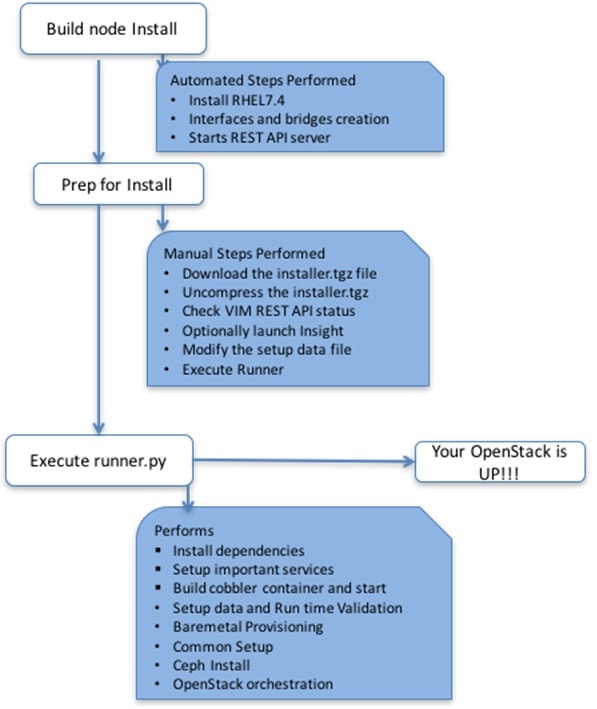

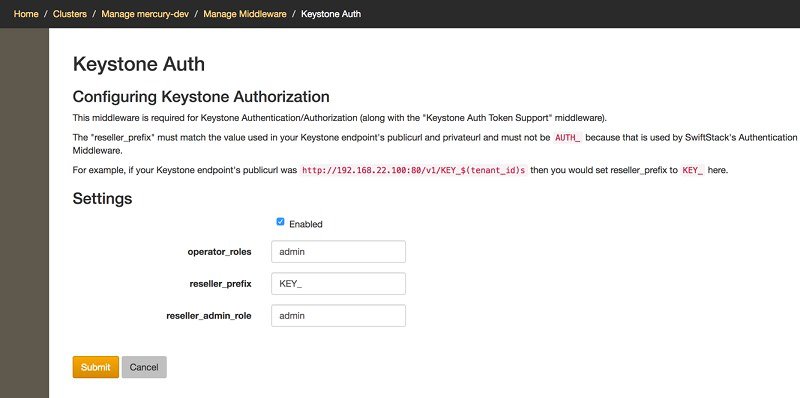
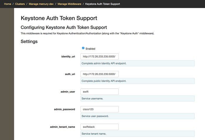
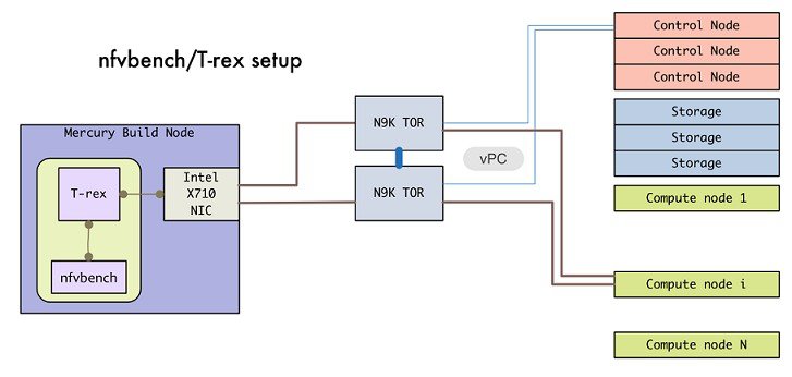
 Feedback