Cisco Evolved Programmable Network Manager 2.1.2 User and Administrator Guide
Bias-Free Language
The documentation set for this product strives to use bias-free language. For the purposes of this documentation set, bias-free is defined as language that does not imply discrimination based on age, disability, gender, racial identity, ethnic identity, sexual orientation, socioeconomic status, and intersectionality. Exceptions may be present in the documentation due to language that is hardcoded in the user interfaces of the product software, language used based on RFP documentation, or language that is used by a referenced third-party product. Learn more about how Cisco is using Inclusive Language.
- Updated:
- August 21, 2017
Chapter: Add and Organize Devices
- Which Devices Are Supported by Cisco EPN Manager ?
- Which Device Software Versions Are Supported by Cisco EPN Manager ?
- How Often Is Inventory Collected?
- Configure Devices So They Can Be Modeled and Monitored
- Configure Devices To Forward Events To Cisco EPN Manager
- Required Settings—Cisco IOS Device Operating System
- Required Settings—Cisco IOS XE Device Operating System
- Required Settings—Cisco IOS XR Device Operating System
- Required Settings—Cisco NCS 4000 Series Devices
- Required Settings—Cisco ONS Device Operating System
- Required Configuration for IPv6 Devices
- Apply Device Credentials Consistently Using Credential Profiles
- Add Devices to Cisco EPN Manager
- Import Devices Using a CSV File
- Add Devices Manually (New Device Type or Series)
- Example: Add a Single Cisco NCS 2000 or NCS 4000 Series Device
- Example: Add a Network Element as an ENE Using Proxy Settings
Add and Organize
Devices
Which Devices Are Supported by Cisco EPN Manager ?
Cisco Evolved Programmable Network Manager Supported Devices provides complete information about items such as:
-
Supported device types and their sysObjectIDs
-
Supported device software versions (see Which Device Software Versions Are Supported by Cisco EPN Manager ?)
-
Supported inventory elements, such as modules, ports, and interfaces (physical and logical)
-
Supported device configuration tasks (interfaces, routing protocols, and so forth)
-
Supported configuration file archiving and software image management features
-
Supported monitoring areas, such as device and interface health, reachability and availability, performance, and technology-specific monitoring
-
Supported topology features, such as LLDP and CDP
-
Supported MIBs used by monitoring policies
The table also provides information about all new support that is provided in Cisco EPN Manager maintenance packs.
Use either of these methods to view the device support table:
-
From the web GUI—Click
 at the top right corner of the window and choosing
.
at the top right corner of the window and choosing
.
-
From Cisco.com—See Cisco Evolved Programmable Network Manager Supported Devices.
 Note | For the most current information, use the table that is on Cisco.com. |
Which Device Software Versions Are Supported by Cisco EPN Manager ?
All devices should be running a certified device software version. However, certain devices must be running the minimum device software version. Follow the instructions in the table below on how to find out about a device software version.
Cisco EPN Manager may report that a device is running an uncertified device software version. You will likely notice no differences in how Cisco EPN Manager manages devices running an uncertified device software version. It depends on whether the device software version contains fundamental changes (changes to XML interfaces, SNMP commands, MIBs, CLI commands, and so forth). In some cases, Cisco EPN Manager will recognize the device software version but may not provide full support for the device NEs such as new modules.
|
To find this information: |
Do the following: |
|
A list of all certified device software versions |
Refer to Cisco Evolved Programmable Network Manager Supported Devices. |
|
Choose and hover over the "i" in the Software Version column to display a popup. |
|
|
If a managed device is running an uncertified device software version |
Choose , locate the device, and hover your cursor over the "i" in the Last Inventory Collection column. Check if the popup displays Uncertified Software Version. |
|
From the device's Device Details page, under the Device Details tab, choose . Check if the Inventory area displays [Uncertified Software Version]. |
|
|
Devices that require a minimum device software version |
Choose and check the Software Version column for text similar to >=x.x (For example, >=12.2 would indicate that the device must run at least device software version 12.2). |
How Often Is Inventory Collected?
After devices are added and discovered, Cisco EPN Manager will collect physical and logical inventory information and save it to the database. The following table describes how inventory collection is triggered.
|
Inventory Collection Trigger |
Description |
||||
|---|---|---|---|---|---|
|
In response to incoming events |
Cisco EPN Manager receives an incoming NE SNMP trap, syslog, or TL1 message that signals a change on the NE. These incoming events include:
Cisco EPN Manager reacts to these incoming events by collecting NE inventory and state information to make sure that information in its database conforms to that of the NE. Most events trigger granular inventory collection, where Cisco EPN Manager only collects data relevant to the change event; other events will trigger a complete collection (sync) of the NE physical and logical inventory. The data that Cisco EPN Manager collects is determined by information in the incoming event, along with metadata that is defined in Cisco EPN Manager . The metadata in Cisco EPN Manager uses a combination of mechanisms—expedited events, reactive inventory, and granular polling—to fine-tune what is collected. For example, if Cisco EPN Manager receives a GMPLS Tunnel State Change event, it will collect ODU tunnel inventory information to discover midpoints and the Z endpoint of the tunnel. |
||||
|
On demand |
Users can perform an immediate inventory collection (called Sync) from:
See Collect a Device's Inventory Now (Sync).
|
||||
|
Scheduled (daily) |
Normal inventory collection is usually performed overnight. Users with sufficient privileges can check when inventory is collected and the status of collection jobs by choosing and choosing System Jobs > Inventory and Discovery Jobs. |
||||
Enable archive logging on devices
Follow these steps to enable archive logging on devices so that granular inventory can be enabled for those devices on Cisco EPN Manager :
For Cisco IOS-XR devices:
logging  <epnm server ip>  vrf default severity alerts
logging  <epnm server ip>  vrf default severity critical
logging  <epnm server ip>  vrf default severity error
logging  <epnm server ip>  vrf default severity warning
logging  <epnm server ip>  vrf default severity notifications
logging  <epnm server ip>  vrf default severity info
snmp-server host <epnm server ip>  traps version 2c public
For Cisco IOS-XE devices:
logging host <epnm server ip>  transport udp port 514
logging host <epnm server ip>  vrf Mgmt-intf transport udp port 514
snmp-server host <epnm server ip>  traps version 2c public
Configure Devices So They Can Be Modeled and Monitored
- Configure Devices To Forward Events To Cisco EPN Manager
- Required Settings—Cisco IOS Device Operating System
- Required Settings—Cisco IOS XE Device Operating System
- Required Settings—Cisco IOS XR Device Operating System
- Required Settings—Cisco NCS 4000 Series Devices
- Required Settings—Cisco ONS Device Operating System
- Required Configuration for IPv6 Devices
- Configure Devices To Forward Events To Cisco EPN Manager
- Required Settings—Cisco IOS Device Operating System
- Required Settings—Cisco IOS XE Device Operating System
- Required Settings—Cisco IOS XR Device Operating System
- Required Settings—Cisco NCS 4000 Series Devices
- Required Settings—Cisco ONS Device Operating System
- Required Configuration for IPv6 Devices
Configure Devices To Forward Events To Cisco EPN Manager
To ensure that Cisco EPN Manager can query devices and receive events and notifications from them, you must configure devices to forward events to the Cisco EPN Manager server. For most devices, this means you must configure the devices to forward SNMP traps and syslogs.
For other devices (such as some optical devices), it means you must configure the devices to forward TL1 messages.
If you have a high availability deployment, you must configure devices to forward events to both the primary and secondary servers (unless you are using a virtual IP address; see Using Virtual IP Addressing With HA).
In most cases, you should configure this using the snmp-server host command. Refer to the topics in this document that list the prerequisites for the different device operating systems.
Required Settings—Cisco IOS Device Operating System
snmp-server host server_IP
snmp-server community public-cmty RO
snmp-server community private-cmty RW
snmp-server ifindex persist
Do not change the device's default packet size (which 1500 bytes). SNMP requests are sent in bulk by default. A small packet size could result in truncated responses.
The following setting disables domain lookups (which can cause Telnet command delays):
no ip domain-lookup
The following syslog settings are required.
logging server_IP
logging on
logging trap informational
logging buffered 64000 informational
logging event link-status default
The following syslog is required if the device has a management IP address (interface_name is the active management IP address):
logging source-interface interface_name
Required Settings—Cisco IOS XE Device Operating System
snmp-server host server_IP
snmp-server community public-cmty RO
snmp-server community private-cmty RW
snmp-server ifindex persist
Do not change the device's default packet size (which 1500 bytes). SNMP requests are sent in bulk by default. A small packet size could result in truncated responses.
This setting disables domain lookups (which can cause Telnet command delays):
no ip domain-lookup
The following syslog settings are required.
logging server_IP
logging on
logging trap informational
logging buffered 64000 informational
logging event link-status default
The following syslog is required if the device has a management IP address (interface_name is the active management IP address):
logging source-interface interface_name
Required Settings—Cisco IOS XR Device Operating System
If you are using Cisco NCS 4000 Series devices, do not complete the steps in this topic. Instead, complete the steps described in Required Settings—Cisco NCS 4000 Series Devices
snmp-server host server_IP
domain ipv4 host server_name server_IP
telnet ipv4 server max-servers no-limit
snmp-server community community_name SystemOwner
snmp-server community community_name RO
snmp-server entityindex persist
snmp-server ifindex persist
vty-pool default 0 99
xml agent tty
netconf agent tty
service timestamps log datetime show-timezone msec year
Do not change the device's default packet size (which 1500 MB). SNMP requests are sent in bulk by default. A small packet size could result in truncated responses.
In addition to the required settings, you must follow these guidelines:
- Install the Cisco IOS XR Manageability Package (MGBL) on top of the Cisco IOS XR version. You can get information on this package from the release notes for your Cisco IOS XR version.
- Use the device login user that is a member of group root-system and cisco-support.
- User should use the admin user unique Telnet login user@admin (and also be a member of groups root-system and cisco-support).
- The devices must have one of the following SNMP community privileges: SDROwner, SystemOwner or the default (which means no specific level was specified). You may configure this as needed, using the following guidelines. (The following command is one line.)
snmp-server community [clear | encrypted] community-string [view view_name] [RO | RW]
[SDROwner | SystemOwner] [access_list_name]
The snmp-server command takes the following arguments.
The following syslog settings are also required.
logging server_IP
logging on
logging trap informational
logging facility local7
logging events level informational
logging events link-status software-interfaces
In the following syslog, the range indicates the minimum of 307200 and maximum of 125000000 log messages that can be stored on the device.
logging buffered <307200-125000000>
This syslog is required if the device has a management IP address (interface_name is the active management IP address):
logging source-interface interface_name
If the device was added using its virtual IP address, configure it as follows:
ipv4 virtual address use-as-src-addr
Required Settings—Cisco NCS 4000 Series Devices
Ensure that both the MPLS and K9 packages are installed on the device before completing the following steps.
-
Cisco EPN Manager uses SSH to secure communication with Cisco NCS 4000 Series devices. To enable SSH, apply the following configuration settings on the device:
ssh server v2
ssh server rate-limit 600
-
In MPLS traffic engineering configuration mode, enable event logging:
mpls traffic-eng logging events all
-
Set the VTY options:
line default
exec-timeout 10 0
session-limit 10
session-timeout 100
transport input ssh
transport output ssh
vty-pool default 0 99 line-template default
-
Configure the Netconf and XML agents:
xml agent tty
netconf agent tty
-
Configure SNMP on the device:
snmp-server host server_IP
snmp-server community public RO SystemOwner
snmp-server community private RW SystemOwner
snmp-server ifindex persist
You can use either SNMPv2 or SNMPv3:
-
For SNMPv2 only, configure the community string:
snmp-server community ReadonlyCommunityName RO SystemOwner
-
For SNMPv3 only, configure the following settings:
snmp-server user User Group v3 auth sha encrypted Password priv des56 encrypted Password SystemOwner
snmp-server view Group 1.3.6 included
snmp-server group Group v3 priv notify Group read Group
For configuring the polling and configuration view, choose one of the following configuration options:
-
SNMPv3 default configuration (used for SNMPv3 polling and viewing of the default configuration): snmp-server group Group v3 priv read v1default write v1default notify v1default
-
SNMPv3 specific configuration:
-
For SNMPv3 polling only:
snmp-server group Group v3 priv
-
For viewing configuration for SNMPv3 set, polling, and for traps/informs notifications:
snmp-server group Group v3 priv notify epnm read epnm write epnm
-
For viewing SNMPv3 - LLDP MIB OID configuration:
snmp-server view Group 1.0.8802.1.1.2 included
-
Note
In the first line, User and Group are two distinct variables that you need to enter values for.
-
-
-
Configure the stats command to improve the SNMP interface stats response time using the configuration Snmp-server ifmib stats cache
-
Configure SNMP traps for virtual interfaces to ensure that link-down scenarios are captured:
snmp-server interface subset 1 regular-expression Hun*
notification linkupdown
!
snmp-server interface subset 2 regular-expression Forty*
notification linkupdown
!
snmp-server interface subset 3 regular-expression Ten*
notification linkupdown
!
-
Syslogs are used by Cisco EPN Manager for alarm and event management. NTP settings ensure that Cisco EPN Manager receives the correct timestamps for events. To configure syslogs on the device, add the following settings:
clock timezone TimeZone
service timestamps log datetime show-timezone msec year
ntp server NTP_Server
update-calendar
logging facility local7
logging Server_IP vrf default severity info [port default]
mpls traffic-eng logging events all
Note the following:
-
When specifying the time zone, enter the time zone's acronym and its difference (in hours) from Coordinated Universal Time (UTC). For example, to specify the time zone for a device located in Los Angeles, you would enter clock timezone PDT -7.
-
Replace Server_IP with the IP address of the host Cisco EPN Manager is installed on.
-
-
Configure the Virtual IP address:
ipv4 virtual address NCS4K_Virtual_IP_Address/Subnet_Mask
ipv4 virtual address use-as-src-addr
Note
NCS4K_Virtual_IP_Address and Subnet_Mask are two distinct variables separated by a slash. Be sure to enter a value for both of these variables.
-
Enable performance management on all optical data unit (ODU) controllers:
controller oduX R/S/I/P
per-mon enable
-
Enable performance management for Tandem Connection Monitoring (TCM):
tcm id {1-6} perf-mon enable -
Configure the Telnet or SSH rate limit for accepting service requests:
-
To open Cisco Transport Controller (CTC) from Cisco EPN Manager (from a Device 360 view), enable the HTTP/HTTPS server:
http server ssl
-
If you plan to use the Configuration Archive feature, devices must be configured as secured. To do this from CTC:
-
If you notice any performance issues because multiple Cisco NCS 4000 Series devices are sending information simultaneously, increase the number of Telnet sessions per second:
cinetd rate-limit 100
Example: Cisco NCS 4000 Device Settings
This example configures Telnet on a Cisco NCS 4000 device using the VRF option, with no timeout:
telnet vrf default ipv4 server max-servers 1-100
vty-pool default 0 99 line-template default
line default
exec-timeout 0 0
Required Settings—Cisco ONS Device Operating System
If you plan to use the Configuration Archive feature, devices must be configured as secured. You can do this from CTC:
Required Configuration for IPv6 Devices
If you want to access a device that uses IPv6 addresses, configure the IPv6 address and static route on the Cisco EPN Manager server (virtual machine) by performing these steps:
Apply Device Credentials Consistently Using Credential Profiles
Credential profiles are collections of device credentials for SNMP, Telnet/SSH, HTTP, and TL1. When you add devices, you can specify the credential profile the devices should use. This lets you apply credential settings consistently across devices.
If you need to make a credential change, such as changing a device password, you can edit the profile so that the settings are updated across all devices that use that profile.
To view the existing profiles, choose Inventory > Device Management > Credential Profiles.
- Create a New Credential Profile
- Apply a New or Changed Profile to Existing Devices
- Delete a Credential Profile
Create a New Credential Profile
Use this procedure to create a new credential profile. You can then use the profile to apply credentials consistently across products, or when you add new devices.
Apply a New or Changed Profile to Existing Devices
Use this procedure to perform a bulk edit of devices and change the credential profile the devices are associated with. This operation overwrites any existing association between a device and a credential profile. You can also use this operation to synchronize device configurations with the new settings.
Note | Make sure the profile’s credential settings are correct before following this procedure and selecting Update and Sync. That operation will synchronize the devices with the new profile. |
Delete a Credential Profile
This procedure deletes a credential profile from Cisco EPN Manager . If the profile is currently associated with any devices, you must disassociate them from the profile.
Add Devices to Cisco EPN Manager
Note | To add a Cisco WLC to Cisco EPN Manager , make sure it does not have any unsupported Access Points (APs), else, Cisco EPN Manager will not discover any APs from that WLC. |
|
Supported Methods for Adding Devices |
See: |
|---|---|
|
Add multiple devices by discovering the neighbors of a seed device using: |
|
|
Add multiple devices using the settings specified in a CSV file |
|
|
Add a single device (for example, for a new device type) |
These topics provide examples of how to add a Carrier Ethernet and an Optical device to Cisco EPN Manager :
-
Example: Add a Single Cisco NCS 2000 or NCS 4000 Series Device
-
Example: Add a Network Element as an ENE Using Proxy Settings
While adding Cisco ME1200 devices in Cisco EPN Manager :
-
SNMP - Use the same SNMP settings as that of other devices.
-
CLI - Ensure that the protocol setting is set to SSH2. Though the device can be reached via telnet using a port, it is recommended to use SSH protocol. If telnet is used, then the custom telnet port used must be 2323.
-
HTTP - Ensure you specify the right http credentials.
-
Remember that configuration changes to Cisco ME1200 devices are not automatically discovered by Cisco EPN Manager . After making a change, you must manually sync the device. To do this, select the required device (s) in the Network Devices table and click Sync.
- Add Devices Using Discovery
- Import Devices Using a CSV File
- Add Devices Manually (New Device Type or Series)
- Example: Add a Single Cisco NCS 2000 or NCS 4000 Series Device
- Example: Add a Network Element as an ENE Using Proxy Settings
Add Devices Using Discovery
Note | Service discovery might take longer than usual when a large number of devices is added during database maintenance windows. Therefore, we recommend that you avoid large-scale operations during the night and on weekends. |
Cisco EPN Manager supports two discovery methods:
-
Ping sweep from a seed device (Quick Discovery). The device name, SNMP community, seed IP address and subnet mask are required. This method is not supported for discovering optical devices. See Run Quick Discovery
-
Using customized discovery methods (Discovery Settings)—This method is recommended if you want to specify settings and rerun discovery in the future. If you want to discover optical devices, use this method. See Run Discovery With Customized Discovery Settings.
Note | If a discovery job rediscovers an existing device and the device's last inventory collection status is Completed, Cisco EPN Manager does not overwrite the existing credentials with those specified in the Discovery Settings. For all other statuses (on existing devices), Cisco EPN Manager overwrites the device credentials with those specified in the Discovery Settings. |
The discovery process of a device is carried out in the sequence of steps listed below. As Cisco EPN Manager performs discovery, it sets the reachability state of a device, which is: Reachable, Ping Reachable, or Unreachable. A description of the states is provided in Device Reachability and Admin States.
-
Cisco EPN Manager determines if a device is reachable using ICMP ping. If a device is not reachable, its reachability state is set to Unreachable.
-
Server checks if SNMP communication is possible or not.
-
If a device is reachable by ICMP but its SNMP communication is not possible, its reachability state is set to Ping Reachable.
-
If a device is reachable by both ICMP and SNMP, its reachability state is Reachable.
-
-
Verifies the device's Telnet and SSH credentials. If the credentials fail, details about the failure are provided in the Network Devices table in the Last Inventory Collection Status column (for example, Wrong CLI Credentials). The reachability state is not changed.
-
Modifies the device configuration to add a trap receiver so that Cisco EPN Manager can receive the necessary notifications (using SNMP).
-
Starts the inventory collection process to gather all device information.
-
Displays all information in the web GUI, including whether discovery was fully or partially successful.
Note | When Cisco EPN Manager verifies a device’s SNMP read-write credentials, the device log is updated to indicate that a configuration change by Cisco EPN Manager (identified by its IP address). |
- Specify the Management IP Address Type (IPv4/IPv6) for Discovered Devices
- Run Quick Discovery
- Run Discovery With Customized Discovery Settings
Specify the Management IP Address Type (IPv4/IPv6) for Discovered Devices
For discovered dual-home (IPv4/IPv6) devices, specify whether you want Cisco EPN Manager to use IPv4 or IPv6 addresses for management IP addresses.
Run Quick Discovery
Use this method when you want to perform a ping sweep using a single seed device. Only the device name, SNMP community, seed IP address and subnet mask are required. If you plan to use the configuration management features, you must provide the protocol, user name, password, and enable password.
See Configure Devices So They Can Be Modeled and Monitored to make sure your devices are configured correctly.
What to Do Next
Click the job hyperlink in the Discovery Job Instances area to view the results.
Run Discovery With Customized Discovery Settings
Cisco EPN Manager can discover network devices using discovery profiles. A discovery profile contains a collection of settings that instructs Cisco EPN Manager how to find network elements, connect to them, and collect their inventory. For example, you can instruct Cisco EPN Manager to use CDP, LLDP, OSPF to discover devices, or just perform a simple ping sweep (an example of the results of a ping sweep is provided in Sample IPv4 IP Addresses for Ping Sweep.) You can also create filters to fine-tune the collection, specify credential sets, and configure other discovery settings. You can create as many profiles as you need.
After you create a profile, create and run a discovery job that uses the profile. You can check the results of the discovery job on the Discovery page. You can also schedule the job to run again at regular intervals.
See Configure Devices So They Can Be Modeled and Monitored to make sure your devices are configured correctly so that Cisco EPN Manager can discover them.
Sample IPv4 IP Addresses for Ping Sweep
The following table provides an example of the results of a ping sweep.
|
Subnet Range |
Number of Bits |
Number of IP Addresses |
Sample Seed IP Address |
Start IP Address |
End IP Address |
|
255.255.240.0 |
20 |
4094 |
205.169.62.11 |
205.169.48.1 |
205.169.63.254 |
|
255.255.248.0 |
21 |
2046 |
205.169.62.11 |
205.169.56.1 |
205.169.63.254 |
|
255.255.252.0 |
22 |
1022 |
205.169.62.11 |
205.169.60.1 |
205.169.63.254 |
|
255.255.254.0 |
23 |
510 |
205.169.62.11 |
205.169.62.1 |
205.169.63.254 |
|
255.255.255.0 |
24 |
254 |
205.169.62.11 |
205.169.62.1 |
205.169.63.254 |
|
255.255.255.128 |
25 |
126 |
205.169.62.11 |
205.169.62.1 |
205.169.63.127 |
|
255.255.255.192 |
26 |
62 |
205.169.62.11 |
205.169.62.1 |
205.169.63.62 |
|
255.255.255.224 |
27 |
30 |
205.169.62.11 |
205.169.62.1 |
205.169.63.30 |
|
255.255.255.240 |
28 |
14 |
205.169.62.11 |
205.169.62.1 |
205.169.63.14 |
|
255.255.255.248 |
29 |
6 |
205.169.62.11 |
205.169.62.9 |
205.169.63.14 |
|
255.255.255.252 |
30 |
2 |
205.169.62.11 |
205.169.62.9 |
205.169.63.10 |
|
255.255.255.254 |
31 |
0 |
205.169.62.11 |
|
|
|
255.255.255.255 |
32 |
1 |
205.169.62.11 |
205.169.62.11 |
205.169.62.11 |
Example: Add Optical Devices Using Discovery
The following example shows how to use to use a seed device and the OTS protocol to discover Cisco NCS 2000 devices.
| Step 1 | Check Configure Devices So They Can Be Modeled and Monitored to make sure the optical devices are configured correctly. | ||
| Step 2 | Choose , then click Discovery Settings at the top right of the window. | ||
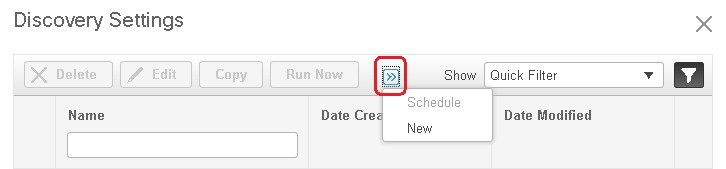
| Step 3 | In the Discovery
Settings window, click
New to create a new discovery profile.
| ||
| Step 4 | Click
Save to save the new discovery profile. The new
NCS2k_3_OTS profile is added to the Discovery
Settings window.
| ||
| Step 5 | Select NCS2k_3_OTS, then click Run Now to begin the discovery job. | ||
| Step 6 | Check the results of the job by choosing . |
Import Devices Using a CSV File
Use a CSV file to add devices if you have an existing management system from which you want to import devices, or you want to specify different values in a spreadsheet.
Create the CSV File
Create the bulk import
CSV file using the template that is available from the Bulk Import dialog box.
To open the dialog box, choose
, click the
 icon above the Network Devices table, and choose
Bulk
Import. Use the
bulk device add sample template.
icon above the Network Devices table, and choose
Bulk
Import. Use the
bulk device add sample template.
To find out what the
different fields mean and which fields are required, use the information that
is in the web GUI. The information is the same for adding a single device or
adding devices in bulk. To get this information, choose
,
click the
icon above the Network Devices table, then choose
Add Device. Mandatory fields are indicated by an
asterisk; fields that require an explanation display a question mark next to
them (hover your mouse cursor over the question mark to view the field
details).
When you are done, save your changes and note the location of the file so you can import it as described in Import the CSV File.
Import the CSV File
Follow this procedure to import devices using a CSV file.
See Configure Devices So They Can Be Modeled and Monitored to make sure your devices are configured correctly.
| Step 1 | Choose Inventory > Device Management > Network Devices. |
| Step 2 | Click the
icon above the Network Devices table, then choose
Bulk
Import.
|
| Step 3 | In the Bulk Import dialog: |
| Step 4 | Check the status of the import by choosing . |
| Step 5 | Click the arrow to expand the job details and view the details and history for the import job. If you encounter any problems, see Validate Added Devices and Troubleshoot Problems. |
Add Devices Manually (New Device Type or Series)
Use this procedure to add a new device type and to test your settings before applying them to a group of devices.
See Configure Devices So They Can Be Modeled and Monitored to make sure your devices are configured correctly.
Example: Add a Single Cisco NCS 2000 or NCS 4000 Series Device
Cisco NCS 2000 series devices are TL1-based devices, and Cisco EPN Manager uses the TL1 protocol to communicate with these devices. Cisco NCS 4000 series devices, on the other hand, are Cisco IOS-XR devices, and Cisco EPN Manager uses the SNMP and Telnet/SSH protocols to communicate with these devices
| Step 1 | Check Configure Devices So They Can Be Modeled and Monitored to make sure the Cisco NCS devices are configured correctly. |
| Step 2 | Click the
icon above the Network Devices table, then choose
Add
Device.
|
| Step 3 | In the Add Device dialog box, complete the required fields. Click the "?" next to a field for a description of that field. |
| Step 4 | Click Verify Credentials to validate that Cisco EPN Manager can reach the device. |
| Step 5 | Click Add to add the device to Cisco EPN Manager . |
Example: Add a Network Element as an ENE Using Proxy Settings
Messages sent to a particular network element must pass through other NEs in the network. To pass messages, one or more nodes can be a Gateway Network Element (GNE) and connect other NEs in your network. A node becomes a GNE when you establish a TL1 session and enter a command that must be sent to another node. The node that receives the TL1 message from another node for processing is an End-point Network Element (ENE). Messages from an ENE are transmitted through a GNE to other NEs in the network.
| Step 1 | Check Configure Devices So They Can Be Modeled and Monitored to make sure your devices are configured correctly. |
| Step 2 | Click the
icon above the Network Devices table, then choose
Add
Device.
|
| Step 3 | In the Add Device dialog box, under the General Parameters, enter the IP address or the DNS name of the ENE that you want to add. Click the "?" next to a field for a description of that field. |
| Step 4 | Under the TL1 Parameters, enter the proxy IP address for the node that you are using as an ENE. |
| Step 5 | Click Verify Credentials to validate that Cisco EPN Manager can connect to the device. |
| Step 6 | Click Add to add the device to Cisco EPN Manager . |
Check a Device's Reachability State and Admin Status
Use this procedure to determine whether Cisco EPN Manager can communicate with a device (reachability state) and whether it is managing that device (admin status). The admin status also provides information on whether the device is being successfully managed by Cisco EPN Manager .
| Step 1 | Choose . |
| Step 2 | Locate your device in the Network Devices table. |
| Step 3 | Check the information in the Reachability and Admin Status columns. See Device Reachability and Admin States for descriptions of these states. |
Device Reachability and Admin States
Device Reachability State—A device's reachability status represents whether Cisco EPN Manager can communicate with the device using all configured protocols.
|
Icon |
Device Reachability State |
Description |
Troubleshooting |

|
Reachable |
Cisco EPN Manager can reach device using SNMP. |
— |

|
Ping reachable |
Cisco EPN Manager can reach device using Ping, but not via SNMP. |
Although ICMP ping is successful, check for all possible reasons why SNMP communication is failing. Check that device SNMP credentials are the same in both the device and in Cisco EPN Manager , whether SNMP is enabled on the device, or whether the transport network is dropping SNMP packets due to reasons such as mis-configuration, etc. See Change Basic Device Properties. |

|
Unreachable |
Cisco EPN Manager cannot reach device using Ping. |
Verify that physical device is operational and connected to network. |

|
Unknown |
Cisco EPN Manager cannot connect to the device. |
Check the device. |
Device Admin State—A device's admin state (or status) represents the configured state of the device (for example, if an administrator has manually shut down a device, as opposed to a device being down because it is not reachable by Ping).
|
Icon |
Device Admin State |
Description |
Troubleshooting |

|
Managed |
Cisco EPN Manager is actively monitoring the device. |
Not Applicable. |

|
Maintenance |
Cisco EPN Manager is checking the device for reachability but is not processing traps, syslogs, or TL1 messages. |
To move a device back to managed state, see Move a Device To and From Maintenance State. |

|
Unmanaged |
Cisco EPN Manager is not monitoring the device. |
In the Network Devices table, locate the device and click the "i" icon next to the data in the Last Inventory Collection Status column. The popup window will provide details and troubleshooting tips. Typical reasons for collection problems are:
If a device type is not supported, its Device Type will be Unknown. You can check if support for that device type is available from Cisco.com by choosing , then click Check for Updates. |
|
|
Unknown |
Cisco EPN Manager cannot connect to the device. |
Check the device. |
Move a Device To and From Maintenance State
When a device's admin status is changed to Maintenance, Cisco EPN Manager will not poll the device for inventory changes, nor will it process any traps or syslogs that are generated by the device. However, Cisco EPN Manager will continue to maintain existing links and check the device for reachability.
See Device Reachability and Admin States for a list of all admin states and their icons.
Validate Added Devices and Troubleshoot Problems
To monitor the discovery process, follow these steps:
| Step 1 | To check the discovery process, choose . | ||
| Step 2 | Expand the job
instance to view its details, then click each of the following tabs to view
details about that device's discovery:
| ||
| Step 3 | To verify that
devices were successfully added to
Cisco EPN Manager
,
choose
. Then:
If you need to edit the device information, see Change Basic Device Properties. To verify that Cisco EPN Manager supports a device, refer to Cisco Evolved Programmable Network Manager Supported Devices. To verify that
Cisco EPN Manager
supports a device, click the Settings icon ( |
Find Devices With Inventory Collection or Discovery Problems
Use the quick filter to locate devices that have discovery or collection problems.
| Step 1 | Choose to open the Network Devices page. |
| Step 2 | Make sure Quick Filter is listed in the Show drop-down at the top left of the table. |
| Step 3 | Place your cursor in the quick filter field above the Collection Status and select a status from the drop-down list that is displayed. The devices are filtered according to that status. For troubleshooting steps, see Validate Added Devices and Troubleshoot Problems. |
Export Device Information to a CSV File
When you export the device list to a file, all device information is exported into a CSV file. The file is then compressed and encrypted using a password you select. The exported file includes device credentials but does not include credential profiles.
 Caution | Handle the CSV file with care because it lists all credentials for the exported devices. You will want to ensure that only users with special privileges can perform a device export. |
| Step 1 | Choose . |
| Step 2 | Select the devices that you want to export, then click Export Device. |
| Step 3 | In the Export Device dialog box, enter an password that will be used to encrypt the exported CSV file. Users will need to supply this password to open the exported file. |
| Step 4 | Confirm the encryption password and click Export. Depending on your browser configuration, you can save or open the compressed file. |
Create Groups of Devices for Easier Management and Configuration
Organizing your devices into logical groupings simplifies device management, monitoring, and configuration. Because you can apply operations to groups, grouping saves time and ensures that configuration settings are applied consistently across your network. In smaller deployments where all devices can be configured with the same settings, you may only need to create one general device group. The grouping mechanism also supports subgroups. You will see these groups in many of the Cisco EPN Manager GUI windows.
When a device is added to Cisco EPN Manager , it is assigned to a location group named Unassigned. If you are managing a large number of devices, be sure to move devices into other groups so that the Unassigned Group membership does not become too large.
- How Groups Work
- Create User-Defined Device Groups
- Create Location Groups
- Create Port Groups
- Make Copies of Groups
- Hide Groups That Do Not Have Any Members
- Delete Groups
How Groups Work
Groups are logical containers for network elements, such as devices and ports. You can create groups that are specific to your deployment—for example, by device type or location. You can set up a group so that new devices are automatically added if they match your criteria, or you may want to add devices manually.
For information on the specific types of groups, see the related topics Network Device Groups and Port Groups.
For information on how elements are added to groups, see How Elements Are Added to Groups: Dynamic, Manual, and Mixed Groups.
- Network Device Groups
- Port Groups
- How Elements Are Added to Groups: Dynamic, Manual, and Mixed Groups
- Groups and Virtual Domains
Network Device Groups
The following table lists the supported types of network device groups.
|
Network Device Group Type |
Membership Criteria |
Can Be Created or Edited By Users? |
|
Device Type |
Devices are grouped by family (for example, Optical Networking, Routers, Switches and Hubs, and so forth). Under each device family, devices are further grouped by series. New devices are automatically assigned to the appropriate family and series groups. For example, a Cisco ASR 9006 would belong to Routers (family) and Cisco ASR 9000 Series Aggregation Services Routers (series). You cannot create a device type group; these are dynamic groups that are system-defined. Instead, use device criteria to create a user-defined group and give it an appropriate device name. Device type groups are not displayed in Network Topology maps. |
No |
|
Location |
Location groups allow you to group devices by location. You can create a hierarchy of location groups(such as theater, country, region, campus, building, and floor) by adding devices manually or by adding devices dynamically. A device should appear in one location group only, though a higher level “parent” group will also contain that device. For example, a device that belongs to a building location group might also indirectly belong to the parent campus group. By default, the top location of the hierarchy is the All Locations group. All devices that have not been assigned to a location appear under the Unassigned group under All Locations. |
Yes |
|
User Defined |
Devices are grouped by a customizable combination of device and location criteria. You can customize group names and use whatever device and location criteria you need. |
Yes |
Port Groups
The following table lists the supported types of port groups.
|
Port Group Type |
Membership Criteria |
Can be created or edited by users? |
|
Port Type |
Grouped by port type, speed, name, or description. Ports on new devices are automatically assigned to the appropriate port group. You cannot create Port Type groups. Instead, use device criteria to create a user-defined group, and create subgroups under the user-defined group. |
No; instead create a User Defined Group |
|
System Defined |
Grouped by port usage or state. Ports on new devices are automatically assigned to the appropriate port group. Link Ports—Ports that are connected to another Cisco device or other network devices and are operating on “VLAN” mode and are assigned to a VLAN. Trunk Ports—Ports that are connected to a Cisco device or other network devices(Switch/Router/Firewall/Third party devices) and operating on “Trunk” mode in which they carry traffic for all VLANs. If the status of a port goes down, it is automatically added to Unconnected Port group. You cannot delete the ports in this group, and you cannot re-create this group as a sub group of any other group. Wireless and Data Center devices use the other System Defined port groups: AVC Configured Interfaces, UCS Interfaces, UCS Uplink Interfaces, WAN Interfaces, and so forth. You cannot create System Defined Port groups. Instead, use device criteria to create a user-defined group, and create subgroups under the user-defined group. |
No; instead create a User Defined Group |
|
User Defined |
Grouped by a customizable combination of port criteria, and you can name the group. If the group is dynamic and a port matches the criteria, it is added to the group. |
Yes |
How Elements Are Added to Groups: Dynamic, Manual, and Mixed Groups
How elements are added to a group depends on whether the group is dynamic, manual, or mixed.
|
Method for Adding Devices |
Description |
|
Dynamic |
Cisco EPN Manager automatically adds a new element to the group if the element meets the group criteria. While there is no limit to the number of rules that you can specify, the performance for updates may be negatively impacted as you add more rules. |
|
Manual |
Users add the elements manually when creating the group or by editing the group. |
|
Mixed |
Elements are added through a combination of dynamic rules and manual additions. |
The device inheritance in parent-child user defined and location groups are as follows:
-
User Defined Group—When you create a child group:
-
If the parent and child groups are both dynamic, the child group can only access devices that are in the parent group.
-
If the parent group is static and the child group is dynamic, the child group can access devices that are outside of the parent group.
-
If the parent and child groups are dynamic and static, the child group "inherits” devices from the parent device group.
-
-
Location Group—The parent group inherits the child group devices.
Groups and Virtual Domains
While groups are logical containers for elements, access to the elements is controlled by virtual domains. This example shows the relationship between groups and virtual domains.
-
A group named SanJoseDevices contains 100 devices.
-
A virtual domain named NorthernCalifornia contains 400 devices. Those devices are from various groups and include 20 devices from the SanJoseDevices group.
Users with access to the NorthernCalifornia virtual domain will be able to access the 20 devices from the SanJoseDevices group, but not the other 80 devices in the group. For more details, see "Create Virtual Domains to Control User Access to Devices".
Create User-Defined Device Groups
To create a new device type group, use the user-defined group mechanism. You must use this mechanism because device type groups are a special category used throughout Cisco EPN Manager . The groups you create will appear in the User Defined category.
Note | Cisco ASR satellites can only belong to location groups. For more information, see Satellite Considerations in Cisco EPN Manager. |
To create a new group, complete the following procedure:
| Step 1 | Choose . | ||
| Step 2 | In the Device Groups pane, click the + (Add) icon and then choose Create User Defined Group. | ||
| Step 3 | Enter the group's name and description. If other user-defined device type groups already exist, you can set one as the parent group by choosing it from the Parent Group drop-down list. If you do not select a parent group, the new group will reside in the User-Defined folder (by default). | ||
| Step 4 | Add devices to the new group:
If you want to add devices that meet your criteria automatically, enter the criteria in the Add Devices Dynamically area. To group devices that fall within a specific range of IP addresses, enter that range in square brackets. For example, you can specify the following:
If you want to add devices manually, do the following:
| ||
| Step 5 | Click the Preview tab to see the members of your group. | ||
| Step 6 | Click Save.
The new device group appears in the folder you selected in Step 3. |
Create Location Groups
Note | Cisco ASR satellites can only belong to Location Groups. For more information, see Satellite Considerations in Cisco EPN Manager. |
To create a location group, follow these steps:
| Step 1 | Choose . |
| Step 2 | In the Device Groups pane on the left, click the Add icon, then choose Create Location Group. |
| Step 3 | Enter the name and description, and choose a group from the Parent Group drop-down list. By default, the group will be an All Locations subgroup (that is, displayed under the All Locations folder). |
| Step 4 | If you are creating a device group based on geographical location, for example, all devices located in a building at a specific address, select the Geographical Location check box and specify the GPS coordinates of the group or click the View Map link and click on the required location in the map. The GPS coordinates will be populated automatically in this case. Note that location groups defined with a geographic location are represented by a group icon in the geo map. The devices you add to the group will inherit the GPS coordinates of the group. See Device Groups in the Geo Map for more information. Note that if geographical location is the primary reason for grouping a set of devices, it is recommended that the devices you add to the group do not have their own GPS coordinates that are different from the group's. |
| Step 5 | If you want
devices to be added automatically if they meet certain criteria, enter the
criteria in the
Add
Device Dynamically area. Otherwise, leave this area blank.
While there is no limit on the number of rules that you can specify for a dynamic group, as the number of rules increases, the group update performance could become slower. |
| Step 6 | If you want to add devices manually: |
| Step 7 | Click the Preview tab to see the group members. |
| Step 8 | Click Save, and the new location group appears under the folder you selected in Step 3 (All Locations, by default). |
Create Port Groups
To create a port group, follow these steps:
| Step 1 | Choose . |
| Step 2 | From , hover your mouse over the "i" icon next to User Defined and click Add SubGroup from the popup window. |
| Step 3 | Enter the name and description, and choose a group from the Parent Group drop-down list. By default, the port group will be under the User Defined folder. |
| Step 4 | Choose the devices a port must belong to in order to be added to the group. From the Device Selection drop-down list, you can: |
| Step 5 | If you want
ports to be added automatically if they meet your criteria, enter the criteria
in the
Add Port
Dynamically area. Otherwise, leave this area blank.
While there is no limit on the number of rules that you can specify for a dynamic group, as the number of rules increases, the group update performance could become slower. |
| Step 6 | If you want to add devices manually: |
| Step 7 | Click the Preview tab to see the group members. |
| Step 8 | Click Save, and the new port group appears under the folder you selected in Step 3 (User Defined, by default). |
Make Copies of Groups
When you create a duplicate of a group, Cisco EPN Manager names the group CopyOfgroup-name by default. You can change the name, if required.
To duplicate a group follow these steps:
| Step 1 | Choose . |
| Step 2 | Choose the group from the Device Groups pane on the left. |
| Step 3 | Locate the device group you want to copy, then click the "i" icon next to it to open the pop-up window. |
| Step 4 | Click Duplicate Group (do not make any changes yet) and click Save. Cisco EPN Manager creates a new group called CopyOfgroup-name. |
| Step 5 | Configure your group as described in Create User-Defined Device Groups and Create Location Groups. |
| Step 6 | Verify your group settings by clicking the Preview tab and examining the group members. |
| Step 7 | Click Save to save the group. |
Hide Groups That Do Not Have Any Members
By default, Cisco EPN Manager will display a group in the web GUI even if the group has no members. Users with Administrator privileges can change this setting so that empty groups are hidden—that is, they are not displayed in the web GUI. (Hidden groups are not deleted from Cisco EPN Manager .)
Delete Groups
Delete Devices
When you delete a device, Cisco EPN Manager will no longer model or monitor it.
If a device has services on it that were provisioned using Cisco EPN Manager , you must delete those services before deleting the device. However, you will be permitted to delete devices that have discovered services on it (that is, services that were not created by Cisco EPN Manager ). To find out which services are on a device, use the Device 360 view; see View a Specific Device's Circuits/VCs.
 Feedback