- Introduction
- Getting Started
- Managing Automation Packs
- Performing advanced console tasks
- Authoring Processes
- Authoring Categories
- Advanced Authoring
- Monitoring Operations
- Performing Basic Console Tasks
- Performing Administrative Actions
- Working with Events and Triggers
- Using Adapters
- Using the PowerShell Snap-in CLI
- Managing High Availability and Resiliency
- Target General Tab
- Target Configuration Tab
- Target Permission Tab
- Target General Information
- Completin g the New Objec t Wizard Panel
- User Assignments tab
- Prerequisites
- Getting Started Using the Remedy Adapter
- Defining a Remedy Server Target
- Managing Remedy Tasks
- Creating a Remedy Entry
- Initiating an Incident Request Review
- Creating a Relationship Between an Incident Request and a Problem
- Adding Properties to a Remedy Activity
- Configuring Relationship Configuration Item Properties
- Adding Incident Properties to a Remedy Trigger
- Adding a New Work Info Entry to an Existing Remedy Property
- Deleting a Remedy Entry
- Finding Remedy Objects
- Get Remedy Entry Property Values
- Get Remedy Incident Property Values
- Defining an Update Remedy Entry Activity
- Defining an Update Remedy Incident Activity
- Selecting a Remedy Form
- Configuring Relationship Incident Properties
- Selecting an Association Type
- Attaching a File to a Remedy Activity
- Instance Properti es
- Create Remedy Entry
- Create Remedy Entry Results
- Create Remedy Incident
- Create Remedy Incident Results
- Create Remedy Relationship, Configuration
- Create Remedy Relationship, Incident
- Create Remedy Relationship, Item
- Create Remedy Relationship Results
- Create Remedy Work Info
- Create Remedy Work Info Results
- Delete Remedy Entry
- Find Remedy Objects
- Find Remedy Objects, Results
- Get Remedy Entry Property Values
- Get Remedy Entry Property Values, Results
- Get Remedy Incident Property Values
- Get Remedy Incident Property Values, Results
- Update Remedy Entry
- Update Rem edy Incident
- Element Descriptions
- Getting Started Using the Prime Service Catalog Adapter
- Configuring the Service Catalog Server Adapter Reconnection Properties
- Defining a Cisco Prime Service Catalog Server Target
- Automating Cisco Prime Service Catalog Adapter Activities
- Defining the Create Service Item Activity
- Defining the Complete Service Request Activity
- Defining the Create Service Item from Table Activity
- Defining the Delete Service Item Activity
- Defining the Delete Service Item from Table Activity
- Defining the Find Service Item Activity
- Defining the Get Service Item Activity
- Defining the Delete Service Item from Table Activity
- Defining the Get User Information Activity
- Defining the Re port Requi sition Status Activity
- Defining the Submit Service Request Activity
- Defining the Update Service Item Activity
- Defining the Update Service Item from Table Activity
- Defining the Update Service Request Activity
- Defining the Cancel Service Request Activity
- Defining the Execute Python Script
- Execute Python Code Properties
- Python Code Results
- Typical Cisco Prime Service Catalog Tasks
- Instance Properties
- Cancel Service Request
- Complete Service Request
- Create Service Item
- Create Service Items from Table
- Delete Service Item
- Delete Service Items from Table
- Find Service Items, Advanced
- Find Service Items, Results
- Find Service Items, Service Item
- Find Service Item, Subscription
- Get Service Item
- Get User Information
- Get User Information Results
- Submit Service Request
- Submit Service Request, Advanced
- Submit Service Request, Results
- Update Service Item
- Update Service Items from Table
- Update Service Request
- Update Service Request, Parameters
- Getting Started Using the Core Adapter
- Configuring the Core Function Adapter
- Defining Core Adapter Activities
- Defining the Calculate Date Activity
- Defining the Calculate Date Time Difference Activity
- Defining the Cast Target Type Activity
- Defining the Convert JSON to XML Activity
- Defining the Convert XML to JSON Activity
- Defining the Correlate Process Event Activity
- Defining the Create Automation Summary Activity
- Defining the Export Table to HTML Activity
- Defining the Find Target Activity
- Defining the Format Date Activity
- Defining the Insert Event Activity
- Defining the Match Regular Expression Activity
- Defining the Parse Date Activity
- Defining the Ping Hosts Activity
- Ping Hosts Results
- Defining the Publish Metric Activity
- Defining the Raise Process Event
- Defining the Set Multiple Variables Activity
- Modifying the Value of a Defined Variable
- Defining the Sleep Activity
- Defining the Test FTP Destination Activity
- Defining the Update Target Activity
- Defining the XPath Query Activity
- Defining the XSL Transform Activity
- Defining th e JSON Path Q uery Ac tivity
- Getting Started Using the SNMP Adapter
- Configuring the SNMP Adapter
- Configuring Listening Port Settings
- Defining an SNMP Device (Agent) Target
- Defining an SNMP Device (Manager) Target
- Defining a SNMP Credentials Account
- Defining a SNMP Trap Received Trigger
- Automating SNMP Device (Agent) Command Activities
- Adding a Variable to an SNMP Activity
- Defining an SNMP Credentials Account
- Automating SNMP Device (Manager) Command Activities
- Getting Started Using the Terminal Adapter
- Configuring the Terminal Adapter
- Defining Terminal Adapter Targets
- Defining Terminal Adapter Runtime Users
- Automating Terminal and Secure Shell (SSH) Activities
- Defining a Close Terminal Session Activity
- Defining a Get File Activity
- Adding a Remote File to a Get File Activity
- Defining a Put File Activity
- Adding a Local File to a Put File Activity
- Defining an Execute Unix/Linux SSH Command Activity
- Defining an Execute Unix/Linux SSH Script Activity
- Defining an Open Terminal Session Activity
- Troubleshooting the Terminal Adapter
- Getting Started Using the Cisco UCS Software Adapter
- Creating a Cisco UCS Manager Target
- Specifying Cisco UCS Default Assignment
- Creating a Cisco UCS Fault Trigger
- Automating a Cisco UCS Activity
- Defining the Associate UCS Service Profile to Server Activity
- Defining the Create UCS Service Profile From Template
- Defining the Correlate UCS Faults Activity
- Defining the Associate UCS VLAN To vNIC Activity
- Defining the Collect UCS Statistics Activity
- Defining the Create UCS Configuration Backup Activity
- Defining the Disassociate UCS Service Profile Activity
- Defining the Execute UCS Manager Command Activity
- Inserting Formatted Date Into Activity
- Defining the Modify UCS Service Profile Activity
- Defining the Disassociate UCS VLAN from VNC Activity
- Defining the Modify UCS VLAN Settings Activity
- Defining the Reset UCS Server Activity
- Defining the Shutdown UCS Server Activity
- Getting Started Using the VMware vSphere Adapter
- Configuring the VMware vSphere Adapter
- Managing VMware vSphere Targets
- Managing VMware Triggers
- Automating VMware vSphere Activities
- Adding an Optical Drive to a Virtual Machine
- Adding a Physical Adapter to a vSphere Distributed Switch
- Adding a Hard Disk to a Virtual Machine
- Adding a Network Adapter to a Virtual Machine
- Cloning a Virtual Machine
- Creating a Folder
- Creating a New Virtual Machine
- Customizing the Linux OS of a Virtual Machine
- Customizing the Windows OS of a Virtual Machine
- Deleting a Virtual Machine
- Retrieving the Datastores in a Virtual Machine
- Retrieving the Networks in a Virtual Machine
- Retrieving the Resource Pools in a Virtual Machine
- Finding the Managed Object Reference
- Migrating a Virtual Machine
- Querying the List of VM Devices on a Virtual Machine
- Querying the Network Adapters on a Virtual Machine
- Querying the Properties of a Virtual Machine
- Querying the Virtual Machines on an ESX or vCenter Server
- Reconfiguring the Virtual Machine on an ESX or vCenter Server
- Relocating a Virtual Machine
- Removing a Virtual Machine from a vCenter Server
- Mounting an ISO Image
- Removing a Folder
- Unmounting an ISO Image
- Updating a Hard Disk on a Virtual Machine
- Updating a Network Adapter on a Virtual Machine
- Upgrading the Hardware on a Virtual Machine
- Upgrading the VM Tools on a Windows Virtual Machine
- Retrieving Reso urce Pools
- Managing VMware vSphere Host Activities
- Adding a New Host
- Adding a New Host Port Group
- Adding a Host to a vSphere Distributed Switch
- Moving a VM Host Server to Maintenance Mode
- Moving a VM Host Server from Maintenance Mode to Online
- Powering Down an ESX Host Server to Standby State
- Powering Up a Host Server from Standby State
- Querying the Network Adapters on an ESX Server
- Querying the Properties of a Host Server
- Querying the Storage Adapters for a Host Server
- Querying the List of Hosts
- Rebooting a VM Host Server
- Removing an ESX Host
- Removing a Host from a vSphere Distributed Switch
- Removing an Adapter from a vSphere Distributed Switch
- Shutting Down a Host
- Updating a Host Port Group
- Managing VMware vSphere Power Activities
- Defining the Execute a PowerCLI Script
- Powering Off a Virtual Machine
- Powering On Virtual Machine
- Rebooting a Guest Operating System on a Virtual Machine
- Resetting the Power on a Virtual Machine
- Shutting Down a Guest Operating System on a Virtual Machine
- Moving a Guest Operating System on a Virtual Machine to Standby Mode
- Suspending a Virtual Machine
- Managing VMware vSphere Snapshot Activities
- Creating a Snapshot of a Virtual Machine
- Querying the Properties of a Virtual Machine Snapshot
- Managing the Virtual Machine Snapshots
- Removing All Snapshots of a Virtual Machine
- Removing a Specific Snapshot of a Virtual Machine
- Renaming a Snapshot of a Virtual Machine
- Restoring a Virtual Machine to the Most Current Snapshot
- Reverting a Virtual Machine to a Specific Snapshot
- Taking a Snapshot of a Virtual Machine
- Getting Started Using the Web Services Adapter
- Defining a Web Target
- Defining an OAuth Credential Account
- Automating Web Services Adapter Activities
- Defining a URL Ping Activity
- Defining a Web HTTP Request Activity
- Defining a Web HTTP Save File Activity
- Defining a Web Service Execute Activity
- Selecting a Web Service Method
- Defining the Web Service Parameters
- Defining the HTTP Headers
- Adding Customized Header Requests
- Defining the Build Class Properties
- Modifying the List of Headers
- Defining Cookie Properties for Web Service Activity
- Inserting a Web Service Cookie Data Table Reference Property
- Viewing Web Service Activity Results
- Getting Started Using the Microsoft Windows Adapter
- Defining a Microsoft Windows Target
- Defining a Windows User
- Creating a Microsoft Windows Event Trigger
- Automating Microsoft Windows Adapter Activities
- Defining the Control Windows Service Activity
- Defining a Windows Ping Activity
- Defining a Correlate Windows Event Activity
- Defining the Copy Folders Activity
- Defining the NSLookup Activity
- Defining the Execute Windows Command Activity
- Defining Uninstall Application Activity
- Defining Trace Route Activity
- Defining the Execute Windows PowerShell Script Activity
- Defining Copy Folders Activity
- Defining the Execute Windows Script Activity
- Adding a Script Argument
- Define a Stop a Windows Process Properties Activity
- Defining the Query Windows Events Activity
- Defining the Read File Activity
- Defining Get Folder Properties Activity
- Defining the Query Windows Performance Counter Activity
- Defining Restart Server Activity
- Defining the Query Windows Registry Activity
- Defining the Query Windows Service Activity
- Defining the Create Folder Activity
- Selecting a Registry Key
- Defining the Update Windows Registry Activity
- Defining the Update Windows Service Activity
- Defining the Write File Activity
- Overview
- Configuring Terminal Adapter
- Managing Terminal Objects
- Defining a Network Device Module Target
- Defining a Terminal Target
- Defining a Unix Linux System Target
- Configuring Total Concurrent Sessions
- Defining Terminal Activities
- Overview
- Defining a Close Terminal Session Activity
- Defining a Get File Activity
- Defining a Put File Activity
- Defining an Execute Terminal Command Activity
- Defining an Execute Unix/Linux SSH Command Activity
- Defining an Execute Unix/Linux SSH Script Activity
- Defining a Stop a Unix Process via SSH Properties
- Defining an Open Terminal Session Activity
- Modifying Terminal Activities
- Adding a Script Argument
- Command Line Examples
- Script Argument Example
- Script Argument Syntax
- Viewing Terminal Activity Results
- Viewing Execute Terminal Command(s) Results
- Viewing Close Terminal Session Output
- Viewing Executed Unix/Linux SSH Command Output
- Viewing Executed Unix/Linux SSH Script Output
- Viewing Get File Activity Results
- Viewing Open Terminal Session Ou tput
- Viewing Expect Instance Tab Results
- Viewing Put File Activity Results
- Viewing Get Interface Inputs
- Viewing Get Interface Outputs
- Get Interface List Instance Properties - Inputs
- Get Interface List Instance Properties - Outputs
- Troubleshooting Terminal Adapter
Using Adapters
The topics in this chapter describe the adapters available for Cisco Process Orchestrator, any special information about installing and configuring the adapters, and the activities provided by each adapter. You can use these adapters in a workflow.
Many of the Process Orchestrator tasks that are required to run an activity are common to all or most adapters. For example:
For specific information about installing and configuring an adapter, see the topics in this chapter. For general information about adapters, see Configuring Security.
Before you can create or run processes in your Process Orchestrator environment, you must create the targets on which the processes will run. Targets define specific environments where certain processes, activities, or triggers will run.
You can define a target once and then reuse it in multiple processes. To define a target, see Defining a Target.
Creating Runtime User Accounts
When creating targets, a runtime user account must be specified to be used to connect to the target. The runtime user account stores the information about the user security context for the target.
You can create the runtime user accounts during the process of creating the targets or prior to creating the targets. To create a runtime user account, see Defining Runtime Users.
Triggers are events and conditions in the system that determine how or when the process will be executed. Using a trigger, for example, you can subscribe to an existing queue and fire an event trigger based on the message that is generated. See Creating Triggers.
Target General Tab
Use the General tab to enter general information about a target. The information displayed depends on the configured target.
Target Configuration Tab
Use the Configuration tab to specify the character restrictions for a database identifier. A distinction is made between simple identifiers and special identifiers.
Target Permission Tab
Use the Permission page to define the permissions for SQL commands that can run on the target.
Target General Information
Use the New [Object] Wizard General Information panel to specify the display name and description for the new target.
Completing the New Object Wizard Panel
The Completing the New [Object] Property Wizard panel displays name of the new object.
Review the information to verify that it is correct and click the appropriate button to complete wizard process.
User Assignments tab
Use the User Assignments tab to add and modify security role information between the security principal and the permissions.
The User Assignment tab binds the security principal (either a user or group) and defined security permissions for the security role.
Click this to launch the select User or Group dialog box and change the owner.
Removes the selected principal from the list of the owners assigned to the security role.
Configuring Adapters
Adapters are one of the extensibility mechanisms used to extend Process Orchestrator functionality to integrate with devices, environments, applications, or tools without undergoing core modification. Examples of adapters include:
- The primary adapter for Cisco Process Orchestrator is the Core Functions Adapter. This adapter provides the core features and objects to be used to manage IT processes.
- Microsoft Windows Adapter provides Windows objects, such as the Windows computer target, Windows runtime user, and Windows-related activities.
Use the Administration > Adapters view to display the adapters that are installed with the product and their associated objects.
Viewing Adapter Prerequisites
Each adapter can have prerequisites that must be satisfied before the adapter can be fully functional. For example, the Core Functions Adapter has no prerequisites, but the SAP ABAP Adapter requires the SAP .NET 3.0 connector; without this connector, the SAP ABAP adapter will not function correctly.
Prerequisites apply to particular Process Orchestrator servers, so prerequisites can be satisfied on one server but not on another. This means that sometimes an adapter might be functional on one server and not on another if the prerequisites are not met on that other server. If you are running in a high availability environment, it is important that all required adapter’s prerequisites are satisfied on all Process Orchestrator servers.
To check the status of the prerequisites for each adapter:
Step 1 Choose Administration > Adapters , then double-click an adapter name.
Step 2 In the [adapter name] Adapter Properties dialog, click the Prerequisites tab.
Step 3 If your environment contains more than one server, you can view the prerequisites for each server. Choose Administration > Orchestration Servers > PO Server properties > Prerequisites .
Viewing Adapter Properties
To view general information related to the adapter, the specific functions that the adapter provides, and a history of changes that have been made to the adapter, choose Administration > Adapters > Adapter Properties . The information on the property dialog for each adapter varies.
Advance Message Queuing Protocol (AMQP) Adapter
The Cisco Advanced Message Queuing Protocol (AMQP) software adapter allows you to automate messaging activities on Cisco AMQP instances.
The following table displays activities that are provided by the AMQP adapter. For more information about using these activities, see Getting Started Using the AMQP Adapter.
Publish a text message to a an existing exchange on the AMQP broker. |
|
Get a message from a given queue on the AMQP broker. See Getting a Message. |
|
Getting Started Using the AMQP Adapter
Use the following process to monitor and manage Cisco AMQP instances.
Step 1 Create a Cisco AMQP target (see Defining an AMQP Broker Target).
Step 2 Define a Cisco AMQP command activity (see Automating Cisco AMQP Tasks).
Step 3 View the activity results (see Monitoring Operations).
Receiving Messages Based on a Pattern
You can define policies that automatically trigger specific workflows based on certain AMQP messages. A message-based event starts only when the message matches all of the criteria on both the Content Header and Message pages.
To create the message-based event:
Step 1 Choose AMQP Message Event Properties .
Step 2 Choose an existing queue.
Step 3 Add the message criteria and message body to the message event.
Step 4 Use an AMQP Message Event trigger to fire an event trigger based on the message that is generated.
Defining an AMQP Broker Target
Use the AMQP Broker target to configure the connection information to a vCloud Directory server to be used for process and activities to run against.
Step 1 Choose Definitions > Targets > New > AMQP Broker.
Step 2 On the General panel, enter the required information.
Step 3 On the Connection panel, specify the connection information for the AMQP broker, including:
- Host—The host name or IP address for the AMQP Broker.
- Port—The AMQP protocol port number; the default port is 5672.
- Virtual Host—The virtual host name or IP address for the AMQP Broker.
- Default runtime user—The runtime user required to execute a process or activity against this target.
- SSL enabled—Indicates if SSL is enabled on the AMQP Broker.
- Ignore certificate error— Ignore the certificate error messages when attempting to connect to the service portal.
Step 4 On the Finish panel, click Finish to complete the target definition.
Declaring an AMQP Exchange
Use the Declare Exchange activity to create or check an AMQP broker exchange.
Step 1 In the Process Editor Toolbox, choose AMQP > Declare AMQP Exchange , then drag and drop the activity onto the Workflow pane.
Step 2 Click the General tab and enter the required information.

Note Exchange names must be unique within a virtual host.
Step 3 Click the Declare Exchange tab and specify the information that describes the exchange, including:
- Type— type of exchange you want to declare (see Managing AMQP Messages).
- Durable— Durable exchanges last until they are deleted. Temporary exchanges last until the server shuts-down. Not all scenarios and use cases require durable exchanges.
- Auto delete— Auto-deleted exchanges last until they are no longer used.
- Arguments—Enter the name and value pair arguments for the queue
Step 4 Enter the information in the remaining tabs as necessary, then click Save to complete the activity definition.
Declaring an AMQP Queue
Use the Declare Queue activity to create or check a queue on the AMQP broker. This activity will create a queue if the queue does not already exist.
When you declare a new queue, you can specify various properties that control the durability of the queue and its contents and the level of sharing for the queue.
Step 1 In the Process Editor Toolbox, choose AMQP > Declare AMQP Queue, then drag and drop the activity onto the Workflow pane.
Step 2 Click the General tab and enter the required information.
Note Message queue names must be unique within a virtual host.
Step 3 Click the Declare Queue tab and specify the information that describes the queue, including:
- Durable—Whether the queue is durable or transient. Durable queues survive broker restart whereas transient queues do not (they must be redeclared when the broker comes back online). Not all scenarios and use cases require durable queues.
- Auto delete—Delete the queue when it is empty.
- Exclusive—The queue belongs to the current connection only, and is deleted when the connection closes.
- Arguments—Enter the name and value pair arguments for the queue
Step 4 Enter the information in the remaining tabs as necessary, then click Save to complete the activity definition.
Binding an AMQP Queue to an Exchange
Use the Bind Queue activity to bind a queue to an AMQP broker exchange.
Step 1 In the Process Editor Toolbox, choose AMQP > Bind AMQP Queue, then drag and drop the activity onto the Workflow pane.
Step 2 Click the General tab and enter the required information.
Step 3 Click the Bind Queue tab and specify the information that describes the queue binding, including:
Step 4 Enter the information in the remaining tabs as necessary, then click Save to complete the activity definition.
Publishing a Message
Use the Publish Message activity to publish a text message to an existing exchange on the AMQP broker. The message will be routed to queues as defined by the exchange configuration and distributed when the transaction, if any, is committed.
For example, VMWare vCloud Director can publish vCloud AMQP Messages (also known as blocking tasks, notifications, or call-outs) related to different provisioning tasks. A Process Orchestrator can not only receive these events, but can respond to them to delay execution.
Step 1 In the Process Editor Toolbox, choose AMQP > Publish AMQP Message, then drag and drop the activity onto the Workflow pane.
Step 2 Click the General tab and enter the required information.
Step 3 Click the Publish Message tab and specify the information that describes the message to be published.
Step 4 To define the content header for the message, click Add to display the Content Header dialog box.
Step 5 Click the Message tab to define the header and body of the message. Click Add to display the Message Header dialog box.
Step 6 Enter the information in the remaining tabs as necessary, then click Save to complete the activity definition.
Getting a Message
Use the Get Message activity to retrieve the next available message from a given queue on the AMQP broker.
Note This activity will open and close the channel to get one message; it is not designed to put it into a tight loop. This activity is considered to be a destructive way to get a message from an AMQP queue. The typical way is to subscribe to an AMQP queue.
Step 1 In the Process Editor Toolbox, choose AMQP > Get AMQP Message, then drag and drop the activity onto the Workflow pane.
Step 2 Click the General tab and enter the required information.
Step 3 Click the Get Message tab and specify the information that describes the message to be retrieved, including:
Step 4 Enter the information in the remaining tabs as necessary, then click Save to complete the activity definition.
Purging an AMQP Queue
Use the Purge Queue activity to remove all messages from a queue that are not awaiting acknowledgment on the AMQP broker. In the Process Editor Toolbox on the [AMQP Activity] property page, click the Purge Queue tab, then choose the queue to be purged.
Unbinding an AMQP Queue
Use the Unbind Queue activity to remove the binding between the queue and the exchange. After the binding has been removed, the queue will not receive any more messages until it is bound to another exchange.
Step 1 In the Process Editor Toolbox, choose AMQP > Unbind AMQP Queue , then drag and drop the activity onto the Workflow pane.
Step 2 Click the General tab and enter the required information.
Step 3 Click the Unbind Queue tab and specify the information that describes the queue you want to unbind, including:
Step 4 Enter the information in the remaining tabs as necessary, then click Save to complete the activity definition.
Deleting an AMQP Queue
Use the Delete Queue activity to delete a queue from the AMQP broker. When a queue is deleted, any pending messages are sent to a dead-letter queue if this is defined in the server configuration, and all consumers on the queue are canceled.
Step 1 In the Process Editor Toolbox, choose AMQP > Delete AMQP Queue , then drag and drop the activity onto the Workflow pane.
Step 2 Click the General tab and enter the required information.
Step 3 Click the Delete Queue tab and specify the information that describes the queue you want to unbind, including:
- Name—Name of the queue you want to delete
- Delete only if queue is not used—Indicates if queue will only be deleted if it is not used.
- Delete only if queue is empty—Indicates if queue will only be deleted if it is empty.
Step 4 Enter the information in the remaining tabs as necessary, then click Save to complete the activity definition.
AMQP Activities Instance Properties
Argument Instance Dialog
The Argument display-only dialog box displays additional arguments given on queue declaration, including the name and value for the given key.
AMQP Message Event Instance Properties Message Tab
The Message display-only tab displays the attributes used for routing Header exchanges route messages based on message header matching.
AMQP Message Event Instance Properties, Advanced Tab
The Advanced display-only tab displays the advanced attributes used for the AMQP event.
Bind Queue
The Bind Queue display-only tab displays the defined parameters used for binding a queue to an exchange on the AMQP broker.
Content Header
The Content Header display-only tab displays the properties defined for how the AMQP message displays in the header of the message.
Declare Exchange
The Declare Exchange display-only tab displays the properties used to declare an exchange on the AMQP broker.
Declare Queue
The Delete Queue display-only tab displays the properties used to declare a queue on the AMQP broker.
Delete Queue
The Delete Queue display-only tab displays the properties used to delete a queue on the AMQP broker.
Get Message
The Get Message display-only tab displays the properties used to subscribe to an existing queue and fire an event trigger based on the message criteria.
Message Tab
The Message display-only tab displays the properties used to define the header and body of a message.
Publish Message
The Publish Message display-only tab displays the properties used to define the text message to an existing exchange on the AMQP broker with a routing key.
Purged Messages
The Purged Messages display-only tab displays the properties used to purge messages in a queue on the AMQP broker.
Microsoft Service Bus Adapter
The Microsoft Service Bus Adapter integrates Microsoft Service Bus API into Cisco Process Orchestrator and allows you to automate messaging activities. You can use Microsoft Service Bus implementation for Windows Server 1.1 on premises. For more details see, Getting Started with Service Bus for Windows Server 1.1.
Note You must export certificate to client machine (Process Orchestrator Server) to enable remote clients to connect to a Service Bus for Windows Server.
The following table displays activities that are provided by the Microsoft Service Bus adapter.
Send a message to a given queue. See Sending a Message. |
|
Getting Started Using the Microsoft Service Bus Adapter
Use the following process to monitor and manage Service Bus instances.
Step 1 Create a Microsoft Service Bus target (see Defining an Microsoft Service Bus Target).
Step 2 Define a Microsoft Service Bus activity (see Automating Microsoft Service Bus Tasks).
Step 3 View the activity results (see Monitoring Operations).
Receiving Messages Based on a Pattern
You can define policies that automatically triggers specific workflows based on certain Service Bus messages. A message-based event starts only when the message matches all criteria on both the Content Header and Message pages.
To create the message-based event:
Step 1 Choose Service Bus Message Event Properties .
Step 2 Choose an existing queue.
Step 3 Add the message criteria and message body to the message event.
Step 4 Use an Service Bus Message Event trigger to fire an event trigger based on the message that is generated.
Defining an Microsoft Service Bus Target
Use the Microsoft Service Bus Broker target to configure the connection information to a vCloud Directory server to be used for process and activities to run against.
Step 1 Choose Definitions > Targets > New > Microsoft Service Bus.
Step 2 On the General panel, enter the required information.
Step 3 On the Connection panel, specify the connection information for the Microsoft Service Bus broker, including:
Note You can create 1 or more namespace, when you register in the Microsoft Service Bus portal.
– Server — Enter the host name or IP address.
– Runtime Port — Enter the Runtime port number. By default it is 9354.
– Management Port — Enter the Management Port number. By default it is 9355.
Step 4 Click Ok to complete the target definition.
New Shared Access Key Properties
Use the New Shared access key properties to create an access key for the service bus.
Step 1 Choose Definitions > Targets > New > Microsoft Service Bus.
Step 2 On the Connection panel, choose New > Shared Access Key .
Step 3 Enter the Shared access key name and Shared access key for the Service Bus.
Step 4 Click Ok to complete the key properties definition.
Sending a Message
Use the Send Message activity to publish a text message to an existing exchange on the Service Bus broker. The message is routed to queues as defined by the exchange configuration and distributed when the transaction, if any, is committed.
Step 1 In the Process Editor Toolbox, choose Microsoft Service Bus > Send Message, then drag and drop the activity onto the Workflow pane.
Step 2 Click the General tab and enter the required information.
Step 3 Click the Publish Message tab and specify the information that describes the message to be published.
You can either use the Queue name or Topic name.
Step 4 To define the content header for the message, click Add to display the Content Header dialog box.
Step 5 Click the Message tab to define the header and body of the message. Click Add to display the Message Header dialog box.
Step 6 Enter the information in the remaining tabs as necessary, then click Save to complete the activity definition.
For more detail on Microsoft Service Bus, see Microsoft Service Bus Adapter
Getting a Message
Use the Get Message activity to retrieve the next available message from a given queue.
Step 1 In the Process Editor Toolbox, choose Microsoft Service Bus > Get Message, then drag and drop the activity onto the Workflow pane.
Step 2 Click the General tab and enter the required information.
Step 3 Click the Get Message tab and specify the information that describes the message to be received.
You can either use the Queue name or Subscription name.
Step 4 Enter the information in the remaining tabs as necessary, then click Save to complete the activity definition.
For more detail on Microsoft Service Bus, see Microsoft Service Bus Adapter
Cloud Center Adapter
The Cloud Center adapter integrates Cloud Center API into Cisco Process Orchestrator, so you can automate cloud deployments and control various aspects of cloud infrastructure provided by Cloud Center.
Defining a Cloud Center Target
Use the Cloud Center Target to configure the connection information to the Cloud Center server.
Step 1 Choose Definitions > Targets > New > Cloud Center Server .
Step 2 On the General panel, enter the required information.
Step 3 On the Connection panel, specify the following connection information:
Note The server name is the property of the target which contains the host part of the URI - a registered name or an IP address.
For more information, see https://en.wikipedia.org/wiki/Uniform_Resource_Identifier
Note You can ignore certificate chain errors only, which is useful to test against the servers with self-generated certificates, without importing the certificates on the client machine.
- Runtime user—Select the Runtime user from the drop–down list or choose New to create a New Cloud Center Manage API Access Key.
-
Optional: AMQP Target—Select the appropriate target from the drop–down list.
The list displays AMQP configuration from the Cloud Center, in order to use the Cloud Center trigger you need to select a AMQP target. This will help you monitor actions like Create, Update, or Delete on any service like User, Tenant, or Cloud.
Step 4 Click OK , to create the connection.
New Cloud Center API Access Credentials Properties
Use the New Cloud Center API Access Credentials properties to create an access credentials for the Cloud Center.
Step 1 Choose Definitions > Targets > New > Cloud Center Server.
Step 2 On the Connection panel, choose New > Cloud Center API Access Credentials .
Step 3 Enter the User name for the Cloud Center.
Step 4 Check the API Key check box, and enter the API key.
Step 5 Click OK to complete the key properties definition.
Execute Cloud Center Command
Use the Execute Cloud Center Command activity to execute Cloud Center API command against a Cloud Center server. The Cloud Center activity provides a flexible way to perform the desired action using the request methods. Responses for common information are scanned and displayed as activity results in the Operations Workspace activity instance view.
Step 1 In the Process Editor Toolbox, choose CloudCenter > Execute Cloud Center Command , then drag and drop the activity onto the workflow pane.
Step 2 Click the General tab and enter the required information.
Step 3 Click the Request tab and specify the following information:
For more information, see http://docs.cliqr.com/display/40API/Base+URI+Format.
– GET — To query or view the server information based on a CloudCenter deployment.
– PUT — To replace the entire object for update operations.
– POST — To perform a CloudCenter platform task or creating the resource.
– DELETE — To remove specific aspects of the CloudCenter deployment.
Note The CloudCenter APIs use HTTPS Version 1 to support these request methods.
For more information on HTTPS request methods see, http://docs.cliqr.com/display/40API/HTTPS+Request+Methods
Note GET request is not sent as part of the request and hence cannot have an HTTP message body.
- Timeout — Check the check box and then enter the time period the activity should wait before failing.
Note Click the time unit link to change the time interval.
Step 4 Enter the information in the remaining tabs as necessary, then click Save to complete the activity definition.
Cloud Center Response
The Response tab displays the properties of the HTTP Response received from the API call.
- HTTP Status Code — Displays the Status code of the response. This may indicate whether a request is success or failure.
The Cloud Center API can only return a limited set of HTTP status codes. For more information on HTTP Status codes, see http://docs.cliqr.com/display/40API/CloudCenter+API+Overview#CloudCenterAPIOverview-HTTPStatusCodes.
- HTTP Reason Phrase — Displays the HTTP reason phrase for the process activity.
- HTTP Message Body — Displays the HTTP message body in JSON or XML.
For more information on HTTP response message see, https://en.wikipedia.org/wiki/Hypertext_Transfer_Protocol#Response_message
BMC Remedy Adapter
The Cisco Remedy Adapter provides activities for automating tasks on Cisco Remedy instances. Typical Remedy command activities include:
- Creating an entry in any Remedy form.
- Initiating an incident request review. These reviews can be performed periodically to analyze incident request information and identify potential problems.
Remedy defines an incident as an event that is not part of the standard operation of a service and that causes an interruption to or a reduction in the quality of that service.
Incident management is typically initiated in response to a customer call or automated event, such as an alert from a monitoring system. The primary goal of the incident management process is to restore normal service operation as quickly as possible with minimum disruption.
- Creating a relationship between an incident request and a problem (Remedy does this automatically when a problem investigation is created from an incident request).
- Adding a new Work Info entry, such as files and customer email messages, to an existing Remedy property. Use this activity to add general notes about the current record, such as the date a particular configuration item was deployed, or vendor-related notes, such as a bulletin sent from a vendor.
Note All Cisco Process Orchestrator Remedy activities are based on forms that can be customized by the user. This can cause a misunderstanding as to whether the fields on the forms are required or optional.
The following table displays activities that are provided by the BMC Remedy adapter. For more information about using these activities, see Getting Started Using the Remedy Adapter.
Create an incident on a Remedy server using selected properties. |
|
Configure a relationship between incidents and configuration items. See Creating a Relationship Between an Incident Request and a Problem |
|
Add a new Work Info entry to an existing Remedy property. See Adding a New Work Info Entry to an Existing Remedy Property |
|
Remove entries, such as relationships, work log entries, or custom entries from a Remedy item. |
|
Query objects, configuration items, and other assets to create relationships. It can also be used to find any entry on a Remedy server. |
|
Retrieve property values for a specific entry on a Remedy server. If the entry ID is known, this activity can be a better alternative than the Find Remedy Objects activity, which allows a broader set of parameters. |
|
Retrieve property values for a specific incident on a Remedy server. If the incident ID is known, this activity can be a better alternative than the Find Remedy Objects activity, which allows a broader set of parameters. |
|
Update the entries in a specific Remedy form. This activity can also be used to update the properties in a Work Info or Relationship entries. |
|
Installing Remedy client C API Library Files
The Remedy adapter requires the Remedy client C API libraries to be installed in order to communicate with Remedy servers. Before you can create a Remedy Server target, the dll files must be installed on the Cisco Process Orchestrator server.
Step 1 Download the API zip file from the BMC community site (see https://communities.bmc.com/docs/DOC-33310 ).
Step 2 From the folder where the dll files are extracted, locate the following files:
Step 3 Copy the files to the following folder on the Orchestrator server:
<Install drive>:\Program Files\Cisco\Process Orchestrator\Adapters\Remedy
Step 4 Verify the properties of the dll files and unlock them, if necessary.
Getting Started Using the Remedy Adapter
Use the following process to monitor and manage Cisco BMC Remedy instances.
Step 1 Create a Cisco Remedy target (see Defining a Remedy Server Target).
Step 2 Define BMC Remedy activities:
a. In the Process Editor Toolbox, choose BMC Remedy > [BMC Remedy Activity], then drag and drop the activity onto the Workflow pane.
b. Click the General tab and enter the required information.
c. Click the [Activity-Specific] tabs to define the properties specific to the activity.
d. Enter the information in the remaining tabs as necessary, then click Save to complete the activity definition.
For details about a specific activity, see Managing Remedy Tasks.
Step 3 View the activity results (see Monitoring Operations).
Defining a Remedy Server Target
Use the Remedy Server target to specify the connection information to a Remedy server which is used for processes to run against. Define the Remedy target before attempting to define any Remedy activities. The Remedy target accesses the list of properties on the Remedy server.
Step 1 Choose Definitions > Targets , right-click, and choose New > Remedy Server.
Step 2 Click the General tab and enter the required information.
Step 3 Click the Connection tab to specify the connection information to a Remedy server, including:
Step 4 Click the Polling tab to configure the frequency in which Process Orchestrator queries a Remedy system.
Step 5 Click OK to close the dialog box and complete the procedure.
Creating a Remedy Entry
Use the Create Remedy Entry activity to create an entry in any Remedy form.
A Remedy server must be installed and accessible. For installation information, see the BMC Remedy documentation.
Step 1 In the Process Editor Toolbox, choose BMC Remedy > Create Remedy Entry, then drag and drop the activity onto the Workflow pane.
Step 2 Click the General tab and enter the required information.
Step 3 On the Entry tab, specify the form properties and associated values to be used to create a Remedy entry, then click Add .
Step 4 In the Select Properties box, choose the Remedy server from which the properties will be added to the entry.
Step 5 Enter the information in the remaining tabs as necessary, then click Save to complete the activity definition.
Initiating an Incident Request Review
A Remedy server must be installed and accessible. For installation information, see the BMC Remedy documentation.
Step 1 In the Process Editor Toolbox, choose BMC Remedy > Create Remedy Incident, then drag and drop the activity onto the Workflow pane.
Step 2 Click the General tab and enter the required information.
Step 3 Click the Incident tab, then specify the properties and associated values to be used to create a Remedy incident.
Step 4 Enter the information in the remaining tabs as necessary, then click Save to complete the activity definition.
Creating a Relationship Between an Incident Request and a Problem
Use the Create Remedy Relationship activity to create a relationship between an incident request and a problem (Remedy does this automatically when a problem investigation is created from an incident request). You can use this activity to create the following types of relationships:
- Incident -> Configuration item
- Incident -> Incident
- Configuration -> Incident
- Configuration -> Configuration
Note Because of operations outside of Process Orchestrator control, such as power failure or network outage, only one side of the relationship can be created by the Create Remedy Relationship activity.
A Remedy server must be installed and accessible. For installation information, see the BMC Remedy documentation.
Step 1 In the Process Editor Toolbox, choose BMC Remedy > Create Remedy Relationship, then drag and drop the activity onto the Workflow pane.
Step 2 Click the General tab and enter the required information.
Step 3 Click the Item 1 or Item 2 tab to continue and select the appropriate item to configure the relationship properties.
- Item Type—From the drop-down list, select the appropriate item to configure the relationship properties.
– Incident—See Configuring Relationship Incident Properties.
– Configuration—See Selecting an Association Type.
Step 4 Enter the information in the remaining tabs as necessary, then click Save to complete the activity definition.
Adding Properties to a Remedy Activity
When configuring the activity properties, you might be required to add properties to the activity. Sort the properties list by the column Type so that all of the required fields for your system are displayed at the top of the list.
The Select Properties dialog box is launched when the Add button on the activity-specific property page is clicked. Use the Select Properties dialog box to specify the incident properties for the activity.
Step 1 On the activity-specific property page tab, click Add .
Step 2 From the Add properties from the following server drop-down list, select the appropriate server from the drop down list.
Step 3 Highlight the appropriate incident properties, then click OK .
Step 4 On the Edit Property dialog box, assign a value to the incident property.
Step 5 Repeat Step 2 through Step 4 to add additional incident properties to the activity.
Configuring Relationship Configuration Item Properties
Use the following steps to define the configuration item properties on the Create Remedy Relationship activity.
Step 1 Click the appropriate Item tab, then choose Item Type > Configuration Items.
Step 2 Complete the following configuration item fields, then click Save:
- Reconciliation ID—Enter the reconciliation ID of the Remedy configuration item.
- Configuration item form name—Enter the name of the form containing the configuration properties.
- Association type—Enter the type of incident property to associate with the Remedy item (see Selecting an Association Type).
- Request description—Enter a description to associate with the incident or configuration item. For example, this could be the name of the item or the name of the related item.
Viewing Results
Click the Item display-only tabs to view the properties of the activity.
- Reconciliation ID—reconciliation ID of the Remedy configuration item
- Configuration item form name—name of the form containing the configuration properties
- Association type—type of incident property to associate with the Remedy item
- Request description—description associated with the incident or configuration item.
Adding Incident Properties to a Remedy Trigger
When configuring a Remedy trigger, you can add incident properties to the trigger which can then be used as additional criteria to monitor for incidents. Sort the properties list by the column Type so that all of the required fields for your system are displayed at the top of the list.
The Select Properties dialog box is launched when the Add button on the Incident Update Criteria tab is clicked. Use the Select Properties dialog box to specify the incident properties for the trigger.
A Remedy server must be installed and accessible. For installation information, see the BMC Remedy documentation.
Step 1 Choose the Incident Update Criteria tab, click Add , then choose Wildcard match or Exact match .
Step 2 On the Remedy Incident Updated Properties dialog box, select the incident update type, click Add , then select the appropriate server from the drop down list. The Remedy server incident properties display in the columns.
Step 3 Highlight the appropriate incident properties, then click OK.
Step 4 Assign a value to the incident property, then click OK.
Adding a New Work Info Entry to an Existing Remedy Property
Use the Create Remedy Work Info activity to add general notes about the current record, such as the date a particular configuration item was deployed, or vendor-related notes, such as a bulletin sent from a vendor.
This activity can be used to add attachments, such as files and customer emails to the work info property. For information on adding attachments to the activity, see Attaching a File to a Remedy Activity.
A Remedy server must be installed and accessible. For installation information, see the BMC Remedy documentation.
Step 1 In the Process Editor Toolbox, choose BMC Remedy > Create Remedy Work Info, then drag and drop the activity onto the Workflow pane.
Step 2 Click the General tab and enter the required information.
Step 3 Click the Work Info tab and modify the list of Remedy work info properties. For information about adding attachments to the activity, see Configuring Relationship Incident Properties.
Step 4 Enter the information in the remaining tabs as necessary, then click Save to complete the activity definition.
Deleting a Remedy Entry
Use the Delete Remedy Entry activity to remove entries, such as relationships, work log entries, or custom entries from a Remedy item.
Step 1 In the Process Editor Toolbox, choose BMC Remedy > Delete Remedy Entry, then drag and drop the activity onto the Workflow pane.
Step 2 Click the General tab and enter the required information.
Step 3 Click the Entry tab and enter:
Click Browse to launch the Select a Form dialog box to select the form containing the entry properties to be removed by the activity.
Step 4 Enter the information in the remaining tabs as necessary, then click Save to complete the activity definition.
Finding Remedy Objects
Use the Find Remedy Objects activity to query objects, configuration items, and other assets in order to create relationships. It can also be used to find any entry on a Remedy server.
All Cisco Process Orchestrator Remedy activities are based on forms which can be customized by the user. This may cause user misunderstanding as to whether the fields on the forms are required or optional.
Step 1 In the Process Editor Toolbox, choose BMC Remedy > Find Remedy Entry, then drag and drop the activity onto the Workflow pane.
Step 2 Click the General tab and enter the required information.
Step 3 Click the Criteria tab and enter:
Step 4 Enter the information in the remaining tabs as necessary, then click Save to complete the activity definition.
Get Remedy Entry Property Values
Use the Get Remedy Entry Property Values activity to retrieve property values for a specific entry on a Remedy server. If the entry ID is known, then this activity may be a better alternative than the Find Remedy Objects activity which allows a broader set of parameters.
All Cisco Process Orchestrator Remedy activities are based on forms which can be customized by the user. This may cause user misunderstanding as to whether the fields on the forms are required or optional.
Step 1 In the Process Editor Toolbox, choose BMC Remedy > Get Remedy Entry Property Values, then drag and drop the activity onto the Workflow pane.
Step 2 Click the General tab and enter the required information.
Step 3 Click the Entry tab and enter:
Click Browse to launch the Select a Form dialog box to select the form containing the entry properties to be removed by the activity.
- Entry ID—Enter the Remedy entry ID number or click the Reference tool to select the appropriate Remedy entry value to be retrieved.
Step 4 Enter the information in the remaining tabs as necessary, then click Save to complete the activity definition.
The Properties to Get box displays the list of Remedy properties to be retrieved by the activity.
Get Remedy Incident Property Values
Use the Get Remedy Incident Property Values activity to retrieve property values for a specific incident on a Remedy server. If the incident ID is known, then this activity may be a better alternative than the Find Remedy Objects activity which allows a broader set of parameters.
All Cisco Process Orchestrator Remedy activities are based on forms which can be customized by the user. This may cause user misunderstanding as to whether the fields on the forms are required or optional.
Step 1 In the Process Editor Toolbox, choose BMC Remedy > Get Remedy Incident Property Values, then drag and drop the activity onto the Workflow pane.
Step 2 Click the General tab and enter the required information.
Step 3 Click the Incident Property Values tab and enter:
- Incident ID—Enter the Remedy incident number or click the Reference tool to select the appropriate Remedy incident values to be retrieved
Step 4 Enter the information in the remaining tabs as necessary, then click Save to complete the activity definition.
The Properties to Get box displays the list of Remedy properties to be retrieved by the activity.
Defining an Update Remedy Entry Activity
Use this activity to update the entries in a specific Remedy form, or to update the properties in a Work Info or Relationship entry.
Step 1 In the Process Editor Toolbox, choose BMC Remedy > Update Remedy Entry, then drag and drop the activity onto the Workflow pane.
Step 2 Click the General tab and enter the required information.
Step 3 Click the Entry tab and enter:
- Form Name—Enter the name of the form containing the entry properties.
- Entry ID—Enter the Remedy entry ID number or click the Reference tool to select the appropriate Remedy entry value to be retrieved.
- Properties to update—See Adding Properties to a Remedy Activity
Step 4 Enter the information in the remaining tabs as necessary, then click Save to complete the activity definition.
Defining an Update Remedy Incident Activity
Use this activity to update the properties for a specific Remedy incident.
Step 1 In the Process Editor Toolbox, choose BMC Remedy > Update Remedy Incident, then drag and drop the activity onto the Workflow pane.
Step 2 Click the General tab and enter the required information.
Step 3 Click the Incident tab and enter:
- Incident ID—Enter the Remedy incident number or click the Reference tool to select the appropriate Remedy incident values to be retrieved
- Properties to update—See Adding Properties to a Remedy Activity
Step 4 Enter the information in the remaining tabs as necessary, then click Save to complete the activity definition.
Selecting a Remedy Form
Use the Select a Form dialog box to select the form containing the properties to be added to a Remedy activity. Activities requiring entry IDs will contain the option to locate the appropriate form on the Remedy server.
Step 1 On the Remedy entry activity tab, click Browse .
Step 2 From the Add a form from the following Remedy Server drop-down list, select the appropriate Remedy server target defined in Process Orchestrator. The displayed forms depend on the server that is selected.
Step 3 From the Selected form list, select the appropriate form containing the available properties to add to the Remedy entry. Only one form can be selected at a time.
Step 4 Click OK to select the Remedy form.
Configuring Relationship Incident Properties
Use the following steps to configure the incident properties on the Create Remedy Relationship activity.
Step 1 Click the appropriate Item tab, then choose Item Type > I ncident.
Step 2 Complete the following incident fields, then click Save:
- Incident ID—Enter the Incident ID number of the Remedy incident.
- Association type—Enter the type of incident property to associate with the Remedy item (see Selecting an Association Type).
- Request description—Enter a description to associate with the incident or configuration item. For example, this could be the name of the item or the name of the related item.
Selecting an Association Type
Use the Select a Property Value dialog box to select the appropriate values to associate the relationship with the Remedy item.
Step 1 On the Remedy activity tab, click Browse.
Step 2 From the Select the property value using the Remedy Server drop-down list, select the appropriate Remedy server target defined in Process Orchestrator. The displayed fields depend on the selected Remedy server.
Step 3 From the Selected field value list, select the appropriate fields containing the available properties to add to the Remedy relationship.
Step 4 Click OK to select the Remedy field.
Attaching a File to a Remedy Activity
Use the following steps to attach a file to a Remedy activity. When attaching a file to a Remedy activity, the file path should be a local path accessible on the Process Orchestrator server machine or a network share path.
Note If an attachment is present in the activity, a Windows user must be specified.
Step 1 On the appropriate Remedy activity property page, click the Credentials tab to specify the Windows runtime user for the remedy activity.
Step 2 Check the Use the following credentials for Remedy attachments check box, then specify the credentials to be used to access the attachment.
To view the properties for the selected runtime user, click the Properties icon. To create a runtime user record for the process, click New > [Runtime User] .
Step 3 Click the Remedy activity-specific tab, then click Add .
Step 4 From the Add properties from the following server drop-down list, select the appropriate server.
Step 5 Scroll to the property labeled Attachment , or sort by the Data Type Attachment , and click OK .
When attaching multiple files, use the Attachment property labeled by number (for example, Attachment 1, Attachment 2).
Step 6 In the Attachment field, enter the path to the appropriate file.
Step 7 Click OK to save the attachment to the Remedy activity property and return to the Remedy object tab.
Create Remedy Entry
The Entry display-only tab displays the properties used to add an entry on a Remedy incident.
- Form Name—Name of Remedy form containing the entry properties used for selection by the Create Remedy Entry activity.
The following columns display the list of properties added to the Create Remedy Entry activity.
Create Remedy Entry Results
The Results display-only tab displays the number created by the remedy entry activity.
Create Remedy Incident
The Incident display-only tab displays the list of properties added to the Create Remedy Incident activity.
Create Remedy Incident Results
The Results display-only tab displays the incident number created by the remedy incident activity
Create Remedy Relationship, Configuration
The Item display-only tab displays the properties used to configure relationships between incidents and configuration items.
- Item Type—Selected item used to configure the relationship properties
- Reconciliation ID—ID of the Remedy configuration item
- Configuration item form name—Name of the form containing the configuration properties associated with the activity
- Association type—Type of configuration property to associate with the Remedy item
- Request description—Description associated with the incident or configuration item
The following columns display the list of Remedy properties added to the item.
Create Remedy Relationship, Incident
The Item display-only tab displays the properties used to configure relationships between incidents and configuration items.
- Item Type—From the drop-down list, select the appropriate item to configure the relationship properties.
- Incident ID—Incident ID number of the Remedy incident
- Association type—Type of incident property to associate with the Remedy item
- Request description—Description associated with the incident or configuration item
The following columns display the list of Remedy properties added to the incident.
Create Remedy Relationship, Item
The Item display-only tab displays the properties used to configure relationships between incidents and configuration items.
Create Remedy Relationship Results
The Results display-only tab displays the ID numbers assigned to the newly-linked items.
Create Remedy Work Info
The Work Info display-only tab displays the list of properties added to the Create Work Info activity.
Create Remedy Work Info Results
The Results display-only tab displays the number created by the Create Remedy Work Info activity.
Delete Remedy Entry
The Entry display-only tab displays the properties used to remove an entry from a Remedy item.
Find Remedy Objects
The Criteria display-only tab displays the properties and entries used to query Remedy objects on a Remedy server.
Find Remedy Objects, Results
The Results display-only tab displays the matching properties and entries retrieved by the activity.
Get Remedy Entry Property Values
The Entry display-only tab displays the properties used to retrieve property values of a Remedy entry.
The following columns display the list of properties queried by the activity.
Get Remedy Entry Property Values, Results
The Results display-only tab displays the list of values for the properties retrieved by the activity.
Get Remedy Incident Property Values
The Incident Property Values display-only tab displays the properties used to retrieve property values of a Remedy incident.
The following columns display the list of properties queried by the activity.
Get Remedy Incident Property Values, Results
The Results display-only tab displays the list of values for the properties retrieved by the activity.
Update Remedy Entry
The Entry display-only tab displays the properties used to update the properties of a Remedy entry.
The following columns display the list of properties updated by the activity.
Update Remedy Incident
The Incident Property Values display-only tab displays the properties used to retrieve property values of a Remedy incident.
The following columns display the list of properties updated by the activity.
Select Remedy Properties Dialog Box
Use the Select Properties dialog box to select the properties from a Remedy server target defined in Cisco Process Orchestrator to add to the list. The displayed properties depend on the server selected.
To select multiple properties, press CTRL and hold the key while making the appropriate selections. When completed selecting properties, click OK.
Cisco Prime Service Catalog Adapter
The Cisco Prime Service Catalog adapter establishes a relationship between Cisco Process Orchestrator and the Cisco Prime Service Catalog. In Process Orchestrator, you can:
- Manage services items and service requests in Cisco Prime Service Catalog.
- Create, delete, and update service items using attributes of the service item.
- Submit and update service requests by manually creating dictionaries or browsing for dictionaries in a Cisco Prime Service Catalog Server target.
The following table displays activities that are provided by the Cisco Prime Service Catalog adapter. For more information about using these activities, see Getting Started Using the Prime Service Catalog Adapter.
Getting Started Using the Prime Service Catalog Adapter
Use the following process to monitor and manage Cisco Prime Service Catalog instances.
Step 1 Create a Cisco Prime Service Catalog target (see Defining a Cisco Prime Service Catalog Server Target).
Step 2 Define a Cisco Prime Service Catalog command activity (see Automating Cisco Prime Service Catalog Adapter Activities).
Step 3 View the activity results (see Monitoring Operations).
Configuring the Service Catalog Server Adapter Reconnection Properties
Use the Retry tab to enter the default time period for all Cisco Prime Service Catalog activities to retry to connect to the Service Catalog whenever there are connection failures. This allows the activity to resume running if the Cisco Prime Service Catalog is temporarily unavailable and the running activity was terminated.
To configure the default reconnection time frame:
Step 1 Choose Administration > Adapters > Cisco Prime Service Catalog Adapter , right-click and choose Properties.
Step 2 Click the Retry tab and complete the following reconnection fields:
- Retry time period (minutes)—Enter the number of minutes Process Orchestrator should attempt to connect to the Cisco Prime Service Catalog. (Default: 15 minutes)
- Retry frequency (seconds)—Enter the number of seconds to determine the frequency Process Orchestrator should retry connecting to the Cisco Prime Service Catalog. (Default: 30 seconds)
Defining a Cisco Prime Service Catalog Server Target
Use the Cisco Prime Service Catalog Server (PSC) target to connect to the Cisco Prime Service Catalog and Request Center services. Process Orchestrator will connect the target to the appropriate service based on the activity that attempts to execute.
Step 1 Choose Definitions > Targets , right-click, and choose New > Cisco Prime Service Catalog Server.
Step 2 On the General panel, enter the appropriate information.
Step 3 On the Connection panel, enter the appropriate information, including:
- Service Link port—Port number used to access the service link port server (Default: 6080)
- Request Center port—Port number used to access the request center port (Default: 6080)
- Access Cisco Prime Catalog via Secure Socket Layer (SSL)—If checked, the connection to the Cisco Prime Catalog server will run on the SSL port.
- Ignore Secure Socket Layer (SSL) certificate error—Check this check box to indicate the target should ignore certificate errors when attempting to connect to the service portal.
- Public key GUID—Optional. The GUID of the external encryption key that is used to encrypt the data sent from Cisco Prime Service Catalog to Process Orchestrator via AMQP. This GUID is generated in the Prime Service Catalog server when user configures external encryption keys for AMQP.
Note The Public key GUID information is configured in Cisco Prime Service Catalog Server. This information is entered only when you use Cisco Prime Service Catalog and AMQP features. It is also used to fetch the broker information via PSC nsAPI.
Step 4 Verify the information on the Completing the New Cisco Prime Service Catalog Server Wizard panel and click Finish to close the wizard.
Defining the Create Service Item Activity
Use the Create Service Item activity to create a service item to be delivered in response to a service request. A service item may be a virtual machine type or a user-defined type in the Cisco Prime Service Catalog.
Step 1 In the Process Editor Toolbox, choose Cisco Prime Service Catalog > Create Service Item and drag and drop the activity onto the Workflow pane.
Step 2 Click the General tab and enter the appropriate information.
Step 3 Click the Service Item tab and enter the following information:
- Service item type—Enter the type of physical or virtual asset for the service item. The service item can be a virtual machine or a user-defined item.
- Service item name—Enter the unique name for the service item.
- Channel id—Enter the identifier that uniquely identifies each Service Link task (for example, 82fdbbaf-3310-4156-a4ae-173b9f15e07c).
- Timeout—Enter the time period the activity should wait before failing.
Note Click the time unit link to change the time interval.
Step 4 Modify the list of attributes to be used to create the service item. The attribute properties provide additional data used to create service item.
- Add—Click this button to add a attribute properties pane to the service item. Select one of the following options for adding a attribute.
– Manual attribute—Click this button to add a Properties pane to the Service Item tab. After the pane displays on the tab, click the appropriate to modify the list of properties for the attribute. See Adding a Service Item Attribute.
– Browse for attributes—Click this button to launch the Add Attributes dialog box to search for a attribute on a Cisco Prime Service Catalog server.
- Remove—Click the area around the appropriate attribute properties, then click this button to remove the last set of attribute properties from the service item.
Step 5 Click the Subscription tab to specify the service item owner's login information to be used when connecting to the Cisco Prime Service Catalog. The login ID and organizational unit information must match.
Step 6 Click the Retry tab to enter the default time period for the activity to retry to connect to the Service Catalog if there is a connection failure. This allows the activity to resume running if the Cisco Prime Service Catalog is temporarily unavailable and the running activity was terminated.
The properties entered on this tab override the time period configured on the adapter level.
If the check box remains unchecked, then activity will fail if there is a connection failure.
– Time period (minutes)—Clear the field to manually update the time period for when the activity should retry to connect to the Cisco Prime Service Catalog. (Default: 15 minutes)
– Frequency (seconds)—Clear the field to manually to determine the frequency in which Process Orchestrator should retry connecting to the Cisco Prime Service Catalog. (Default: 30 seconds)
Step 7 Complete the appropriate information in the remaining tabs as necessary, then click Save to complete the activity definition.
Defining the Complete Service Request Activity
Use the Complete Service Request activity to notify Service Catalog that the process is complete. The required Task ID is provided in the AMQP message that initiated the process.
Step 1 On the Toolbox, choose Cisco Prime Service Catalog > Complete Service Request and drag and drop the activity onto the Workflow pane.
Step 2 Click the Service Request tab to specify the following properties:
- Task ID—provided in the AMQP message that initiated the process
- Timeout—Check the check box and then enter the time period the activity should wait before failing.
Note Click the time unit link to change the time interval.
Step 3 Complete the appropriate information in the remaining tabs as necessary, then click Save to complete the activity definition.
Defining the Create Service Item from Table Activity
Use the Create Service Items from Table activity to create multiple service items using a table variable to be delivered in response to a service request in the Cisco Prime Service Catalog.
The table variable should include the service names and values that correspond to the attribute names in the Cisco Prime Service Catalog.
Step 1 In the Process Editor Toolbox, choose Cisco Prime Service Catalog > Create Service Items from Table and drag and drop the activity onto the Workflow pane.
Step 2 Click the General tab and enter the appropriate information.
Step 3 Click the Service Item tab and enter the following information:
For example, the table might contain the following columns for a virtual machine:
Name / IP Address / Host / Memory / DiskSpace
To create multiple VMs from the table, add several rows for the table with the above column values defined.
- Channel id—Enter the identifier that uniquely identifies each Service Link task.
- Timeout—Enter the time period the activity should wait before failing.
Note Click the time unit link to change the time interval.
Step 4 Click the Subscription tab to specify the service item owner's login information to be used when connecting to the Cisco Prime Service Catalog. The login ID and organizational unit information must match.
Step 5 Click the Retry tab to enter the default time period for the activity to retry to connect to the Service Catalog if there is a connection failure. This allows the activity to resume running if the Cisco Prime Service Catalog is temporarily unavailable and the running activity was terminated.
Step 6 Complete the appropriate information in the remaining tabs as necessary, then click Save to complete the activity definition.
Defining the Delete Service Item Activity
Use the Delete Service Item activity to delete an existing service item in the Cisco Prime Service Catalog.
Step 1 On the Toolbox, choose Cisco Prime Service Catalog > Delete Service Item and drag and drop the activity onto the Workflow pane.
Step 2 Enter the service item properties (see Defining the Create Service Item Activity). Enter the unique name for the service item.
Step 3 Complete the appropriate information in the remaining tabs as necessary, then click Save to complete the activity definition.
Defining the Delete Service Item from Table Activity
Use the Delete Service Items from Table activity to delete multiple service items using a table variable in the Cisco Prime Service Catalog.
The table variable should include the service names and values that correspond to the attribute names in the Cisco Prime Service Catalog.
Step 1 In the Process Editor Toolbox, choose Cisco Prime Service Catalog > Delete Service Items from Table and drag and drop the activity onto the Workflow pane.
Step 2 Enter the service item properties (see Defining the Create Service Item from Table Activity).
The table must contain a “Name” column. This column must contain the uniquely named items that are to be deleted.
Step 3 Complete the appropriate information in the remaining tabs as necessary, then click Save to complete the activity definition.
Defining the Find Service Item Activity
Use the Find Service Item activity to search for attribute properties for the service item.
Step 1 In the Process Editor Toolbox, choose Cisco Prime Service Catalog > Find Service Item and drag and drop the activity onto the Workflow pane.
Step 2 Click the Advanced tab to define the service items you want to retrieve.
- Get all matching items—Select this option to retrieve all matching service items
- Get specified row— Start row—enter the row properties you want to retrieve the service item from
- Maximum items to return—enter the number of service items to retrieve
Step 3 Click the Service Item tab to search for attribute properties for the service item.
- Service item type—Enter the type of physical or virtual asset for the service item. The service item can be a virtual machine or a user-defined type.
- Timeout—Enter the time period the activity should wait before failing.
Note Click the time unit link to change the time interval.
Step 4 Modify the list of Search criteria to be used to find service item.
a. Add—Click this button to add a attribute properties pane to the find service item. Select one of the following options for adding a search criteria.
- Manual search criteria—Click this button to add a Properties pane to the Service Item tab. After the pane displays on the tab, click the appropriate to modify the list of properties for the search criteria for the service item type you want to find.
– Attribute—Enter the attribute name to be added to the service item
– Data Type—From the drop-down list, select the data type for the service item.
– Value—Enter the attribute value to be added to the service item
- Browse for search criteria—Click this button to launch the Add Attributes dialog box to search for a attribute on a Cisco Prime Service Catalog server.
b. Remove—Click the area around the appropriate attribute properties, then click this button to remove the last set of attribute properties from the service item.
Step 5 Modify the list of associated attributes to get to be used to find service item.
a. Add—Click this button to add a attribute properties pane to the service item. Select one of the following options for adding a attribute.
- Manual attribute—Click this button to add a Properties pane to the Service Item tab. After the pane displays on the tab, click the appropriate to modify the list of properties for the attribute.
– Attribute name—Enter the attribute name to find service item. Click the Reference tool to browse for the correct variable reference property for the service item.
– Data type—From the drop-down list, select the data type for the service item (such as Boolean, String, Numeric, Date and Time).
- Browse for attributes—Click this button to launch the Add Attributes dialog box to search for a attribute on a Cisco Prime Service Catalog server.
b. Remove—Click the area around the appropriate attribute properties, then click this button to remove the last set of attribute properties from the service item.
Step 6 Click the Subscription tab to define the subscriber, or current owner of the service item, properties.
- Subscriber login id—The unique ID assigned to the current owner of the service item
- Subscriber OU—The organizational unit to which the subscriber belongs
- Include subscriber information in results—Indicates the subscriber information is included in the results retrieved.
Step 7 Complete the appropriate information in the remaining tabs as necessary, then click Save to complete the activity definition.
Defining the Get Service Item Activity
Use the Get Service Item activity to retrieve attribute properties for the service item.
Step 1 In the Process Editor Toolbox, choose Cisco Prime Service Catalog > Get Service Item and drag and drop the activity onto the Workflow pane.
Step 2 On the Service Item tab, enter the service item properties.
- Service item type—Enter the type of physical or virtual asset for the service item. The service item can be a virtual machine or a user-defined type.
- Service item name—Enter the name of the service to be ordered.
Start User Provisioning Process
Note Click the time unit link to change the time interval.
Step 3 Modify the list of associated attributes to get to be used to get service item.
a. Add—Click this button to add a attribute properties pane to the service item. Select one of the following options for adding a attribute.
- Manual attribute—Click this button to add a Properties pane to the Service Item tab. After the pane displays on the tab, click the appropriate to modify the list of properties for the attribute.
– Attribute name—Enter the attribute name to get service item. Click the Reference tool to browse for the correct variable reference property for the service item.
– Data type—From the drop-down list, select the data type for the service item (such as Boolean, String, Numeric, Date and Time).
- Browse for attributes—Click this button to launch the Add Attributes dialog box to search for a attribute on a Cisco Prime Service Catalog server.
b. Remove—Click the area around the appropriate attribute properties, then click this button to remove the last set of attribute properties from the service item.
Step 4 Complete the appropriate information in the remaining tabs as necessary, then click Save to complete the activity definition.
Defining the Delete Service Item from Table Activity
Use the Delete Service Items from Table activity to delete multiple service items using a table variable in the Cisco Prime Service Catalog.
The table variable should include the service names and values that correspond to the attribute names in the Cisco Prime Service Catalog.
Step 1 In the Process Editor Toolbox, choose Cisco Prime Service Catalog > Delete Service Items from Table and drag and drop the activity onto the Workflow pane.
Step 2 Enter the service item properties (see Defining the Create Service Item from Table Activity).
The table must contain a “Name” column. This column must contain the uniquely named items that are to be deleted.
Step 3 Complete the appropriate information in the remaining tabs as necessary, then click Save to complete the activity definition.
Defining the Get User Information Activity
Use the Get User Information activity to retrieve the properties of a specified user.
Step 1 In the Process Editor Toolbox, choose Cisco Prime Service Catalog > Get User Information and drag and drop the activity onto the Workflow pane.
Step 2 Click the User tab to enter the user properties.
- User name—Enter the user name for the user account properties to be retrieved.
- Timeout—Check the check box and then enter the time period the activity should wait before failing.
Note Click the time unit link to change the time interval.
Step 3 Complete the appropriate information in the remaining tabs as necessary, then click Save to complete the activity definition.
Defining the Report Requisition Status Activity
Use the Report Requisition Status activity to report the execution status of the service request on the Cisco Prime Service Catalog.
Step 1 In the Process Editor Toolbox, choose Cisco Prime Service Catalog > Report Requisition Status and drag and drop the activity onto the Workflow pane.
Step 2 Click the Requisition Status tab to enter the task properties.
- Channel ID—Enter the unique Channel ID of the service that is created in the Cisco Prime Service Catalog.
- Parent Task name—Enter the name of the task that is parent of the current task.
- Task name—Enter the name for the task.
- Status—Select the status from the drop–down:
Step 3 Click Save to complete the activity definition.
The following Create Site Branch Operation shows Report requisition status node added to different places of the workflow to report the progress to Cisco Prime Service Catalog (PSC) with reference to the Channel ID mentioned in the activity, here in this process the tasks such as device configuration, create site, and configure IWAN links is performed.
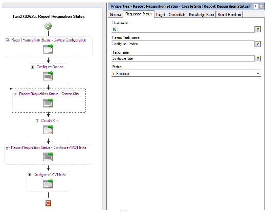
- Initially the device configuration is performed in this workflow, during this process the status is reported as In-progress in PSC for the activity.
- Once the device configuration is completed, the report is sent to the PSC with status succeeded.
- After the device is configured the Create Site is performed, during this process the status is reported as In-progress in PSC for the activity.
- Once the site is created, the report is sent to the PSC with status succeeded.
- After the Site is created the Configure IWAN Links is performed in this workflow, during this process the status is reported as In-progress in PSC for the activity.
- Once the IWAN links are configured, the report is sent to the PSC with status succeeded.
Once the process is succeeded the status is updated as Complete for the service request created in Cisco Prime Service Catalog.
Defining the Submit Service Request Activity
Use the Submit Service Request activity to submit a request for a service order on the Cisco Prime Service Catalog. In this activity, users can add multiple dictionaries to the service request manually or by browsing for an existing dictionary on a target.
Step 1 In the Process Editor Toolbox, choose Cisco Prime Service Catalog > Submit Service Request and drag and drop the activity onto the Workflow pane.
Step 2 Click the Service Request tab to specify the name of the service to be ordered. For example:
Step 3 Modify the list of dictionaries to be used to support the service request. The dictionary properties provide additional data used to request a service and/or fulfill the service request.
– Manual dictionary—Click this button to add a Properties pane to the Service Request tab. After the pane displays on the tab, click the appropriate to modify the list of properties for the dictionary. See Manually Adding a Dictionary.
– Browse for dictionary—Click this button to launch the Add Dictionaries dialog box to search for a dictionary on a Cisco Prime Service Catalog server.
Step 4 Click the Advanced tab to provide default customer login information for the requestor. The information defined on this tab will override the runtime user selected on the Credentials tab.
- Customer login name—Enter the log in name for the customer of the service being requested.
- Initiator login name—Enter the log in name of the person initiating the request for the service.
- Quantity—Enter the quantity needed for the service request. (Default: 1)
- Bill to OU—Enter the organizational unit to be billed for the service request.
Step 5 Complete the appropriate information in the remaining tabs as necessary, then click Save to complete the activity definition.
Defining the Update Service Item Activity
Use the Update Service Item activity to update the attributes for an existing service item on the Cisco Prime Service Catalog.
Step 1 In the Process Editor Toolbox, choose Cisco Prime Service Catalog > Update Service Item and drag and drop the activity onto the Workflow pane.
Step 2 Click the appropriate tabs and update the service item properties as necessary. For details, see Defining the Create Service Item Activity.
Step 3 Complete the appropriate information in the remaining tabs as necessary, then click Save to complete the activity definition.
Defining the Update Service Item from Table Activity
Use the Update Service Items from Table activity to update multiple service items using a table variable in the Cisco Prime Service Catalog. The table variable should include the service names and values that correspond to the attribute names in the Cisco Prime Service Catalog.
Step 1 In the Process Editor Toolbox, choose Cisco Prime Service Catalog > Update Service Items from Table and drag and drop the activity onto the Workflow pane.
Step 2 Click the appropriate tabs and update the service item properties as necessary. For details, see Defining the Create Service Item from Table Activity.
Step 3 Complete the appropriate information in the remaining tabs as necessary, then click Save to complete the activity definition.
Defining the Update Service Request Activity
Use the Update Service Request activity to update an existing service request that currently resides on the Cisco Prime Service Catalog server.
Step 1 In the Process Editor Toolbox, choose Cisco Prime Service Catalog > Update Service Request and drag and drop the activity onto the Workflow pane.
Step 2 Click the General tab and enter the appropriate information.
Step 3 Click the Service Request tab and enter the required information, including:
Note: The identifier for the activity must be retrieved directly from the Cisco Prime Service Catalog. Do not reference an output property of the Submit Service Request activity.
Step 4 Click the Parameters tab to specify the parameters needed by the Service Link to update data on the service request to coordinate the completion of a task.
- Do not send parameters—Select this radio button to indicate that no parameters are required in order to update the task in the service request.
- Send the following parameters—Select this radio button to enable the Parameters pane.
- Send parameters from table variable—Select this radio button to enable the text field.
Step 5 Click the Reference icon to query a table variable to be used for the service request. The table must contain both a "Name" and a "Value" column. The name column must correspond to an attribute name in the service portal.
Defining the Cancel Service Request Activity
Use the Cancel Service Request activity to cancel a request for a service order on the Cisco Prime Service Catalog.
Step 1 In the Process Editor Toolbox, choose Cisco Prime Service Catalog > Cancel Service Request and drag and drop the activity onto the Workflow pane.
Step 2 Click the Service Request tab and select the Requisition ID of the service to be canceled.
Step 3 Enter the time period the activity should wait before failing.
Step 4 Check the Force Monitor Plan Cancellation check box to force the cancellation, if the service request is configured not to allow cancellation after the task has started.
Defining the Execute Python Script
Use the following procedure to execute python script.
Step 1 In the Process Editor Toolbox, choose Code Executions > Execute Python Script and drag and drop the activity onto the Workflow pane.
Step 2 Click the General tab and enter the appropriate information.
Step 3 Click the Execute Python Script tab to specify the commands used to execute an activity.
- Script Name—Enter the name for the Python Program.
- Local windows runtime user that the python code will run on behalf—Enter the runtime user to the local windows that python code will run on behalf.
Note The Windows users must have access to the machine, where the Process Orchestrator server is located at.
- Script arguments—Enter the collection of argument values for the script, users can pass to sys module in Python code. For example:
In windows command line, if to run python script, underlined arguments are set in sys module in python code
The Script argument block here is to provide users capability to pass arguments like arg1, arg2 set in sys module and you can access them via sys.argv[1], sys.argv[2] and so on.
– Add—Click this button and choose one of the following to launch the Select Argument to Add dialog box. Enter the appropriate script in the text field or click Reference icon to select from the list.
– Edit—Select a script argument from the list and click this button to modify the script argument in the Select Argument to Add dialog box.
– Remove—Select a script argument from the list and click this button to remove the script argument from the list.
- Import Module Path—Enter the Path to import module of any custom python code files or any third party python library.
Note The path must exist in Process Orchestrator server machine.
- Script—Enter the script of the python code or click the Reference tool to select from the list.
- Enter the time period the activity should wait before failing.
Step 4 Complete the appropriate information in the remaining tabs as necessary, then click Save to complete the activity definition.
Execute Python Code Properties
The Execute Python Script tab displays the properties used to execute the python script in the Process Orchestrator.
- Script name—Displays the script name of the python program
- Local windows runtime user that the python script will run on behalf—Displays the name of local Windows user
- Script argument—Displays the arguments users can pass to the sys module in python code
- Import module path—Displays the path of the python files
- Script—Displays the python code script
- Wait for command to complete or time out in—Displays the time period the activity should wait before failing
Adding a Service Item Attribute
Use the following steps to add attribute properties to the service item.
Step 1 On the Service Item tab, click Add.
Step 2 Complete the following fields to enter the attributes for the service item.
- Attribute name—Enter the attribute name to be added to the service item. Click the Reference tool to browse for the correct variable reference property for the service item.
- Data type—From the drop-down list, select the data type for the service item (such as Boolean, String, Numeric, Date and Time).
- Value—Enter the value for the associated attribute.
Step 3 Click the Save tool to complete the activity definition
Manually Adding a Dictionary
Use the following options to add a Dictionary properties pane for manually adding a dictionary to the service request.
Step 1 On the Service Request tab, click Add > Manual Dictionary .
Step 2 Under Properties, enter the name of the dictionary to included with the service request.
Step 3 Click Add > [Name] Property to launch the Add Property dialog box to add a property to the dictionary.
- Property name—Enter the name of the dictionary property.
- Native data type—Data type that may not be used by Process Orchestrator, but was retrieved from the Cisco Prime Service Catalog as part of an existing item within a dictionary property. (Ex. Number, Text, Double)
- Data type—Data type assigned to the item
- Required—Check this check box to indicate the property is required.
- Property is multi-valued—Check this check box to indicate more than one value should be assigned to the item.
- Value—Enter the value(s) for the associated property. If the Property is multi-valued check box is checked, complete each Value field, as necessary.
Step 4 Click OK to close the Add Property dialog box and return to the Service Request tab.
Step 5 Click the Save tool to complete the activity definition.
Browsing for Dictionaries
Use the Add Dictionaries dialog box to add dictionaries and their related properties to a service request from a defined Cisco Prime Service Catalog server target. Use the following steps to browse for a dictionary to be included in the service request.
The queried dictionary completes all the fields required for service request.
Step 1 On the Service Request tab, click Add > Browse for Dictionaries.
Step 2 From the Add Dictionaries from the following Cisco Prime Service Catalog server drop-down list, select the appropriate server containing the dictionaries from which you want to query.
Step 3 In the Service name field, enter the service name for the product containing the dictionaries to be used with the service request.
Step 4 Click Refresh to display the dictionaries from the service in the list.
Step 5 Under the Names list, select the appropriate dictionary to be included in the service request, then click OK.
Specifying the Owner for the Service Item
Use the Subscription tab to provide the service item owner's login information to be used when connecting to the Cisco Prime Service Catalog. The login ID and organizational unit information must match the information in the portal.
Step 1 Click the Subscription tab on the service item activity.
Step 2 Complete the fields, as necessary.
Specifying Requestor Credentials for the Service Request
Use the Advanced tab on the Submit Service Request activity to provide login information for the requestor which can be used to override the runtime user credentials configured in the process properties. The login ID and organizational unit information must match the information in the portal.
Step 1 Click the Advanced tab on the Submit Service Request activity.
Step 2 Complete the login and organizational information needed for this activity, as necessary.
- Customer login name—Enter the log in name for the customer of the service being requested.
- Initiator login name—Enter the log in name of the person initiating the request for the service.
- Quantity—Enter the quantity needed for the service request. (Default: 1)
- Bill to OU—Enter the organizational unit to be billed for the service request.
Step 3 Click the Save tool to complete the activity definition.
Cancel Service Request
The Service Request display-only tab displays the properties defined to cancel a service item to be delivered in response to a service request. A service item may be a Virtual Machine type or a user-defined type in the Cisco Prime Service Catalog.
Complete Service Request
The Complete Service Request display-only tab displays the existing service request that completed on the Cisco Prime Service Catalog server.
Create Service Item
The Service Item display only page displays the properties used to create a service item to be delivered in response to a service request in the Cloud Service Portal.
- Service item type—the type of physical or virtual asset for the service item. The service item can be a virtual machine or a user-defined type.
- Service item name—the name of the service to be ordered.
Start User Provisioning Process
- Channel Id (Service Link only)—the identifier that uniquely identifies each Service Link task. If provided, the current SOAP based interface to Service Catalog will be utilized. If not provided, the nsAPI will be used for the implementation of the activity.
- Timeout— the time period the activity should wait before failing.
Note Click the time unit link to change the time interval.
- Attributes—The following options display the properties used to configure the attributes to add to the service item.
– Attribute name—Attribute name to be added to the service item.
Create Service Items from Table
The Service Item display-only page displays the properties used to create multiple service items using a table variable to be delivered in response to a service request in the Cisco Prime Service Catalog.
- Service item type—the type of physical or virtual asset for the service item. The service item can be a virtual machine or a user-defined type.
- Table variable—the table variable data containing the information needed to create the service items.
- Channel Id (Service Link only)—the identifier that uniquely identifies each Service Link task. If provided, the current SOAP based interface to Service Catalog will be utilized. If not provided, the nsAPI will be used for the implementation of the activity.
- Timeout—the time period the activity should wait before failing.
Note Click the time unit link to change the time interval.
Delete Service Item
The Service Item tab displays the properties used to delete an existing service item in the Cisco Prime Service Catalog.
Delete Service Items from Table
The Service Item tab displays the properties used to delete multiple service items using a table variable in the Cisco Prime Service Catalog.
Find Service Items, Advanced
The Advanced read only tab displays the service items that were defined for retrieval.
– Start row—the row properties you want to retrieve the service item from
– Maximum items to return—the number of service items to retrieve
Find Service Items, Results
The Results display-only tab displays the matching service items results.
Find Service Items, Service Item
The Service Item display-only tab displays the attribute properties for the service item.
- Service item type—Enter the type of physical or virtual asset for the service item. The service item can be a virtual machine or a user-defined type.
- Search criteria—Enter the search criteria for the service item type you want to find
– Attribute—Enter the attribute name to be added to the service item
– Data Type—From the drop-down list, select the data type for the service item.
– Value—Enter the attribute value to be added to the service item
Find Service Item, Subscription
The Subscription display-only tab displays the subscriber, or current owner of the service item, properties.
Get Service Item
Display-only. Use the Get Service Item activity to retrieve attribute properties for the service item.
- Service item type—Enter the type of physical or virtual asset for the service item. The service item can be a virtual machine or a user-defined type.
- Service item name—Enter the name of the service to be ordered.
Start User Provisioning Process
Note Click the time unit link to change the time interval.
Get User Information
Display-only.Use the Get User Information activity to retrieve the properties of a specified user.
- User name—Enter the user name for the user account properties to be retrieved.
- Timeout—Check the check box and then enter the time period the activity should wait before failing.
Note Click the time unit link to change the time interval.
Get User Information Results
Use the Results tab to view the response output in the selected format.
Submit Service Request
Display-only. Use the Submit Service Request activity to submit a request for a service order on the Cisco Prime Service Catalog. In this activity, users can add multiple dictionaries to the service request manually or by browsing for an existing dictionary on a target.
The following displays the dictionary and its related properties that were included in the service request.
The following table displays the properties associated with the dictionary assigned to the service request.
Submit Service Request, Advanced
The Advanced display-only tab displays the default customer login information for the requestor used by the service request.
Submit Service Request, Results
The Results tab displays the details of the service request submitted.
- Service Name—Name of the service request submitted
- Requisition ID—Identifier for the service that has been ordered as part of a service request
- Status—Status of the service request
- Started date—Date the service request was started
- Due date—Date the service request should be completed
- Customer login date—Login name of the customer who submitted the request for the service
- Initiator login name—Login name of the person initiating a request for the service
Update Service Item
The Service Item tab displays the attributes used to update an existing service item on the Cisco Prime Service Catalog.
- Channel Id (Service Link only)—Enter the identifier that uniquely identifies each Service Link task. If provided, the current SOAP based interface to Service Catalog will be utilized. If not provided, the nsAPI will be used for the implementation of the activity.
- Service item type—Type of physical or virtual asset for the service item.
- Service item name—Name or IP address of the service item.
This section displays the attributes updated on the service item.
Update Service Items from Table
The Service Item tab displays the properties used to update multiple service items using a table variable in the Cisco Prime Service Catalog.
- Channel Id (Service Link only)—Displays the identifier that uniquely identifies each Service Link task. If provided, the current SOAP based interface to Service Catalog was utilized. If not provided, the nsAPI was used for the implementation of the activity.
- Service item type—Type of physical or virtual asset for the service item
- Table variable—Displays the table variable data containing the information needed to update the service items
Update Service Request
The Service Request display-only tab displays the properties used to update an existing service request that currently resides on the Cisco Service Catalog server.
- Channel Id—Identifier for the Service Link task in the service request to be updated
- Take action—Checked box and completed text field indicates the specific action that should be taken when the service request is updated.
– Approval—Indicates task should be sent for approval
– Cancel—Indicates task should be canceled
– Done—Indicates task should be noted as completed
Update Service Request, Parameters
The Parameters display-only tab provides the properties used on whether to send parameters with the service request and any parameters needed by the Service Link to update the data on the service request.
- Do not send parameters—Selected option indicate that no parameters were required to update the task in the service request.
- Send the following parameters—Selected option indicates that the displayed parameters in the Parameters Column were used to update the service request.
- Send parameters from table variable—Selected option indicates a table variable was used for updating the service request.
The following table displays the parameters that are included in the Update Service Request activity.
- Name—Displays the name of the agent parameter.
- Values—Displays the value assigned to the agent parameter
- Data Type—Data type assigned to the parameter
OpenStack Adapter
The OpenStack adapter establishes a relationship between Cisco Process Orchestrator and OpenStack. In Process Orchestrator, you can perform IT process automation tasks such as provisioning OpenStack resources, monitoring OpenStack installations, troubleshooting operational problems, and so on.
Getting Started Using the OpenStack Adapter
Use the following process to monitor and manage OpenStack instances.
Step 1 Create an OpenStack target (see Defining an OpenStack Server Target).
Step 2 Define an OpenStack user (see Defining an OpenStack User).
Step 3 Define an OpenStack command activity (see Automating OpenStack Adapter Activity).
Step 4 View the activity results (see Monitoring Operations).
Defining an OpenStack User
Use the following instructions to define the user credentials required to access OpenStack. The level of access for the network device is dependent upon the type of user logging in.
Step 1 Choose Definitions > Runtime Users , right-click and choose New > OpenStack User.
Step 2 Click the General tab to specify the required information, including:
- Display name—Enter the display name for the runtime user. This field is populated with the information specified in the User name text field, but can be overwritten by the user.
- Type—Display only. Type of object.
- Owner—User name of the owner of the object. This is typically the person who created the object.
- User name—The user name assigned to access the OpenStack server.
- Password—Check the Password check box and then enter the password assigned to access the OpenStack server.
Step 3 Click OK to close the dialog box.
Defining an OpenStack Server Target
Use the OpenStack Server target to connect to the OpenStack server.
Step 1 Choose Definitions > Targets , right-click, and choose New > OpenStack Server.
Step 2 On the General panel, enter the appropriate information.
Step 3 On the Connection panel, enter the appropriate information, including:
- OpenStack server name—Enter the host name or the IP address of the OpenStack server.
- Override default URL—Select this option to enter an appropriate URL to use to override the default URL.
- API Version—Select the appropriate API version to which your automation content is associated.
- Ignore Secure Socket Layer (SSL) certificate error—Check this check box to indicate the target should ignore certificate errors when attempting to connect to the service portal.
- Runtime user—Select this radio button to specify the runtime user required to execute a process or activity against this target.
- Project—The project or an organizational unit in the cloud that is used to scope the command. It is also known as tenant.
Step 4 Verify the information on the Completing the New OpenStack Server Wizard panel and click Finish to close the wizard.
Defining the Execute OpenStack Command Activity
Use the Execute OpenStack Command activity to execute OpenStack RESTful API command against an OpenStack server. The Execute OpenStack Command activity provides a flexible way to automatically track authentication tokens and renew them as needed. Responses for common information are scanned and displayed as activity results in the Operations Workspace activity instance view.
Step 1 In the Process Editor Toolbox, choose OpenStack > Execute OpenStack Command and drag and drop the activity onto the Workflow pane.
Step 2 Click the General tab and enter the appropriate information.
Step 3 Click the Request tab and enter the following information:
– Service—The OpenStack services supported by the OpenStack server.
– Endpoint—The endpoint to access the OpenStack service.
From the Insert Variable Reference dialog box, select the reference variable and then enter the rest of the URL to be requested. For example, if you want to request for all the tenants available in the OpenStack service, you can enter [Process.Target.IDentity Endpoints FirstRowAdminURL]/tenants .
- Method—The method to be performed on the resource identified by the Request-URI. For a list of common header methods, see HTTP Header Methods.
- Request Content Type—The value for the content type used to define the structure of the request.
- Request—Enter any additional HTTP request details using JSON or XML format.
- Response Content Type—The value for the content type used to define the structure of the response.
- When request creates a task, wait for its completion (in seconds)—Check the check box to indicate that when a task request is sent using methods, PUT, POST, DELETE, the activity should wait for the specified time period for the completion of the task before continuing.
In the enabled text box, enter the time period the activity should wait for the task. Click the time unit link to change the time interval.
- Rate limit wait time—Enter the number of seconds that the web service call must wait to prevent the call from exceeding the limits.
- Archive request text upon successful activity completion—Check the check box to indicate whether to archive the data request after the successful completion of the activity.
- If the check box remains unchecked, the data generated by the activity is removed from the database upon successful completion of the activity.
- Restart activity if interrupted —Check this check box to indicate the activity should resume after an interruption in the execution.
If the check box remains unchecked, then the activity remains paused if there is an interruption in the execution.
Step 4 Click the Paging tab and enter the following information:
- Limit—Enter the number of items to be displayed on each page. By default, the limit is set to 0 and the search returns all the items.
- Marker—Set the marker to the last item returned in the previous list and then request for subsequent items.
- Page reverse—Check this check box to indicate that the list can be reversed.
Step 5 Complete the appropriate information in the remaining tabs as necessary, then click Save to complete the activity definition.
Cisco Process Orchestrator Adapter Help for Email
Overview
The Email adapter provides the ability to execute email objects and send email messages to a specified user. This guide provides instructions for viewing Email adapter properties, defining Email targets, triggers, and activities, instructions for completing the property pages for each specific activity, and instructions on viewing the activity results.
The Email adapter properties dialog box displays general information about the functionality provided by the adapter, version number, release date and install date, any prerequisites, and the history of changes made to the adapter.
Email Targets Overview
Users can define an email target to run a process or activity against an Internet Message Access Protocol (IMAP) email server, a Post Office Protocol (POP3) email server, or an SMTP Server.
The IMAP email server allows an email client, such as Microsoft Outlook, to retrieve email on a remote mail server. The POP3 email server allows an email client to retrieve e-mail from a remote server over a TCP/IP connection.
An Email (IMAP) target must be connected to an Exchange 2007 Server with Service Pack 3. An authentication failure will occur when attempting to create an Email (IMAP) target against an Exchange 2007 Server that does not have service pack 3.
The following table provides a listing of the targets that are associated with the adapter.
Defining the Email Account Target
Use the following steps to define an Email Account (IMAP) target. This target allows a process or activity to execute against an email account on an IMAP mail server.
An Email (IMAP) target must be connected to an Exchange 2007 Server with Service Pack 3. An authentication failure will occur when attempting to create an Email (IMAP) target against an Exchange 2007 Server that does not have service pack 3.
Step 1 On the Definitions > Targets view, right-click and choose New > Email Account (IMAP).
The New Email Account (IMAP) Properties dialog box displays.
Step 2 On the General Information panel, specify the name and description of the new object, then click Next.
Step 3 On the Email Account settings panel, specify the email server, email user name and port for the email account.
- Email server—Name of the email server that relays email to the mailbox
- Protocol—Display-only field of the type of email protocol being used by the email server
- Email user—Select the default runtime user account used to connect to the target. Select the default runtime user from the drop-down list.
- Port Override—Check the check box and enter the port number in the adjacent field to override the default port used by the protocol if the port is being used by another application.
- Enable TLS authentication—If checked, the authorization of the Email server will use TLS.
- Enable SSL—If checked, the connection to the Email server will run on the SSL port.
Note You may also need to override the default IMAP port (143) to the SSL port.
- Ignore Certificate Error—If checked, any errors regarding the certificate will be ignored.
- Enable server push notifications—If checked, Email Simple or Advanced Events will be monitored through email server push notifications.
Step 4 Click the Keystore tab and enter the key file password that provides access to the file.
Step 5 Click the Advanced tab to specify the reconnection settings to the appropriate email server (IMAP, POP3) after a connection failure.
- Reconnect to email server on connection failure—Check this check box to enable the reconnection settings for the target.
- Reconnect every ____seconds—Select this option and in the text field, enter the number of seconds the target should take to reconnect to the server.
- Reconnect up to—In the text field, enter the maximum number of times the target should attempt to reconnect to the server.
- Attempt to reconnect at the following intervals (in seconds)—Select this option and in the text field, enter the number of seconds the target should wait before attempting to reconnect to the server.
Step 6 Click OK to close the dialog box and complete the procedure.
The new target displays in the list of targets on the Definitions > Targets view.
Viewing Email Properties
Step 1 On the Administration > Adapters view, double-click Email Adapter.
The Properties dialog box displays.
Step 2 Click the Advanced tab to specify the maximum size of a text file attachment which will be returned in the output table in the Get Email Attachments activity.
- Maximum allowed text file size (KB—Choose the maximum number of kilobytes allowed for the text file.
Step 3 Click the Keystore tab and enter the key file password that provides access to the file.
Managing Email Activities
Defining the Email Activity
Use the Email activity to specify the information required for sending an email as part of the process.
Step 1 On the Toolbox pane, under Email Activities, select the Email activity, then drag and drop the activity onto the Workflow pane.
The Email property pages display.
Step 2 On the General tab, enter the appropriate information.
Step 3 Click the Email tab to specify the properties used to generate the email. Use commas to separate multiple email addresses.
- To—Enter the email address of the primary recipient(s) of the email.
- Cc—Enter the email address of the recipient(s) who are to be carbon-copied on the email.
- Bcc—Enter the email address of the recipient(s) who are to blind carbon-copied on the email.
- Subject—Enter the subject heading of the email.
- Message—Enter the content of the message in the body of the email.
Note HTML code can be used for formatting if the email is saved in HTML format.
For example, if the content is <B> Cisco Process Orchestrator </B>, then the contents in the email will be shown in bold text.
Step 4 Click the Attachments tab to specify the file paths for the attachments to be sent as part of the email.
- User with access to attachments—From the drop-down list, select the runtime user account to attach files to the email.
- Attachment Paths—Displays the list of file paths for attachments
Step 5 Click OK to complete the activity definition.
Define a Get Email Attachments Activity
Use the Get Email Attachments activity to specify the parameters for the attachments to be sent as part of the email.
Step 1 On the Toolbox pane, under Email Activities, select the Get Email Attachments activity, then drag and drop the activity onto the Workflow pane.
The Get Attachments tab display.
Step 2 On the Get Attachments tab, specify the properties used for the attachments.
- Mail folder—[Required] mail folder name that contains the message
- Message ID—[Required] the unique message ID.
- Select attachments—Include all the attachments in the message; (b) specify the attachment file table with a “File Name” column, containing attachment file names Usually, user may user the variable reference to the attachment output table from the trigger Email Advanced Event; or (c) Specify the attachment file name, user may use “*” wild card to specify the attachment file name pattern. The default choice is to include all the attachments.
- What to do with the attachments—(a) Download the attachments; or (b) return the text attachment in the output table. Download is the default. If choose to return the text attachment in the output table, the text of the attachment can be referenced in the exposed attachment table. The size of the text attachment file needs to be no larger than the max allowed size specified in the Email Adapter Advanced settings. If oversized, the activity will fail.
- [Optional] If choose to download—Window Runtime User to access file systems for downloading attachments. The default user is “Orchestrator Server User” that was created during product installation.
- [Optional] If choose to download—Directory to save the downloaded files. In high availability environment server setup, the directory should be a network share accessible to all the servers.
- [Optional] Mutually exclusive choices—If you choose to download, what to do if the file exists. The default is ‘Always replace’. The other two choices are ‘Do not replace’ and ‘Replace only if newer’.
Step 3 Click OK to close the dialog box and complete the procedure.
Element Descriptions
Service Request Parsing Rules Page
Use the Service Request Parsing Rule page to set up the predefined XPath query based parsing rule for a given type of the service request payloads.
Add/Edit Property Dialog
Use this dialog to add or edit dictionary properties to/for a service request. Select one of the following data types to the request and enter a value for the associated attribute:
Add Value Dialog Box
Use this dialog box to add or modify the properties and parameters to be included in the service request.
Note The displayed fields depend on the dialog box that is opened.
- Property/Parameter name—Enter the name of the agent parameter or dictionary property.
- Native data type—Display-only. Data type that may not be used by Process Orchestrator, but was retrieved from the Cisco Prime Service Catalog as part of an existing item within a dictionary property. (Ex. Number, Text, Double)
- Data type—Display-only. Data type assigned to the item
XPath Query Page
Use the XPath Query page to fill in the XPath namespaces defined in the service request XML payload.
- Prefix—Enter the prefix element associated with the namespace URI reference in the attribute value
- Uri—Enter the Uniform resource identifier (URI) used to identify the attribute value of the namespace name or resource on the Internet
- Property Name—Enter the property name
- Property Type—Select the data type associated with the path expression to query.
Git Adapter
Configuring Automation Pack Repository Share
Use the following steps to specify how the automation pack repository are to be saved. The file paths specified indicate the path that will be used when viewing the automation pack repository.
To view automation pack repository, it is recommended that Automation pack repositories are saved on a UNC share path.
If the automation pack repository is set to be saved only on the local computer, then only local users will have access to the automation pack repository. The automation pack repository will not display for users with remote access, such as those accessing Process Orchestrator from the web console or the remote client.
Step 1 Choose Administration > Adapters, right-click Git Adapter and choose Properties.
Step 2 Click the Automation Pack Repository Share tab to enter or modify repository and runtime user information.
Share path—Enter the UNC path to a share directory. This path will be used to store automation pack repositories.
Note Verify that the UNC share file path is on a network where the Cisco Process Orchestrator service account has write permissions.
- Select the runtime user account used to connect to the automation pack repository file share. Select the runtime user from the drop-down list.
- To view the properties for the selected runtime user, click the Properties tool.
- To create a new windows user, click New > Windows User to create a new Windows User account.
Creating a New Git Repository
Use the New Git Repository Wizard to create or modify Git repository properties for an automation pack repositories. An example of properties includes values such as repository URL, repository user, branch and code path.
Step 1 The Welcome to the Git Repository Wizard panel displays.
Note If you do not want to display the Welcome panel the next time the wizard is launched, check the Do not show this page next time check box.
Step 2 Click Next to continue to the General Information Panel and specify the name and description.
Step 3 On the Git Repository panel, specify the following information to create a repository:
- Repository URL—Enter the Git URL of the repository.
- Repository User—Select the repository user from the drop–down or click New > Repository User to create a new runtime user. For more information see, Defining a Repository User.
- Branch—Enter default branch name master. As you initially make commits, you are given a master branch that points to the last commit you made.
- Code Path—Enter the code path of the Git.
Core Adapter
The following table displays activities that are provided by the Core Functions adapter. For more information about using these activities, see Getting Started Using the Core Adapter.
Getting Started Using the Core Adapter
Use the following process to monitor and manage Core activity instances.
Step 1 Define a Core command activity (see Defining Core Adapter Activities).
Step 2 View the activity results (see Monitoring Operations).
Configuring the Core Function Adapter
The Core Function Adapter provides the basic functionality in Cisco Process Orchestrator. Use the Core Function Adapter Properties dialog box to configure default email settings, diagnostic report location, and Return on Investment calculations.
Configuring Automation Summary Settings
Automation summary reports are generated by activities to provide information about the activity and assist in resolving any issues that may need attention. Use the following steps to specify how the automation summary reports are to be saved and how long the reports are to be retained. The file paths specified indicate the path that will be used when viewing the automation summary reports.
To view automation summary reports, it is recommended that Automation summary reports are saved on a UNC share path.
If the automation summary is set to be saved only on the local computer, then only local users will have access to the automation summary report. The automation summary will not display for users with remote access, such as those accessing Process Orchestrator from the web console or the remote client.
Step 1 Choose Administration > Adapters, right-click Core Functions Adapter and choose Properties.
Step 2 Click the Automation Summary tab to specify where the automation summary reports that are generated by activities are to be saved and how long the reports are to be retained.
The file paths specified indicate the path that will be used when viewing the automation summary reports.
Step 3 Verify or enter the appropriate default file path for the automation summary directory.
(\\servername\sharename\path\filename)
Note Verify that the UNC share file path is on a network where the Cisco Process Orchestrator service account has write permissions.
Use the following buttons to modify the share path:
Step 4 Specify the default credentials to be used to access the Orchestrator server on the network share.
- Enable virtual directory mapping—Check this check box to map the file path to an IIS Virtual Directory. If the check box is unchecked, then the automation summary will not be saved to a shared or IIS virtual directory and will not be available for view from the Web Console.
- Virtual directory path—Enter the http://host:(port)/sharefolder that corresponds to a virtual directory in IIS. If necessary, go to IIS Manager to create your Web Sites and your Virtual Directory for the share folder. Use the default settings or change the settings, as necessary.
Click Create to launch the Create Virtual Directory dialog box to update the Virtual Directory name.
The file path to the network share where automations may be created and stored.
– Site name—Name of the IIS virtual directory
– Physical path—Display only. File path that corresponds to the virtual directory
– Virtual Directory name—Name of the new shared folder
Select the appropriate directory mapping option from the drop-down list to map the automation summary to a shared directory or IIS Virtual Directory to allow end-users easier access to automation summaries using email or the Process Orchestrator Web Console.
Step 5 Configure the automation summary reports grooming settings.
- Delete automation summary reports older than—Check this check box to limit the number of automation summary reports that are retained. Enter the number of days that the reports should be retained in the text field. Reports that have been retained for a period past the specified number of days will be deleted.
Configuring Return on Investment
Process Orchestrator provides the ability to calculate the Return on Investment (ROI) that is achieved by automating your processes. When you create a process, you have the option to enter the equivalent time it would take to run the process manually. This value is calculated against the hourly rate specified on this page to determine your ROI.
Step 1 Choose Administration > Adapters, right-click Core Functions Adapter and choose Properties.
Step 2 Click the ROI tab and specify the hourly rate (in dollars) that it would cost to execute a process manually.
Getting Task XSL Transforms
Each task type has a specific XSL transform that converts the XML into HTML web pages for display in the Web Console. Use the Task tab to display the default XSLT transform file names. The files are located in the Process Orchestrator program Web Console folder under the following file path:
C://Install Directory/Web Console/Task XSL Transforms
You can change the XSL file name for a specific task when modifying the task properties in the Process Editor dialog box.
Step 1 Choose Administration > Adapters, right-click Core Functions Adapter and choose Properties.
Step 2 Click the Task tab, highlight the appropriate task, and right-click and choose Properties.
The Task XSL Transform dialog box displays the default XSL transform file name for the specific task.
Step 3 To view the converted code, use a web browser to launch the appropriate XSLT file that resides in the Process Orchestrator install directory/WebConsole folder.
Publishing Metrics to the Window Management Instrumentation Provider
Use the WMI tab to configure the default settings for publishing metrics into the Windows Management Instrumentation (WMI) provider.
Step 1 Choose Administration > Adapters, right-click Core Functions Adapter and choose Properties.
Step 3 Click Publish Metrics to enable the settings to configure the publishing time frame, then set these values:
Defining the Calculate Date Activity
Use the Calculate Date activity to manipulate the values of a date/time variable.
Step 1 In the Process Editor Toolbox, choose Core Activities > Calculate Date, then drag and drop the activity onto the Workflow pane.
Step 2 Click the General tab and enter the required information.
Step 3 Click the Calculate Date tab to specify the properties to be used to adjust the date and time frame.
Format must be according to the regional settings. (mm/dd/yyyy hh:mm:ss)
Step 4 Click the time unit link to change the modified date/time (from seconds up to days).
Step 5 Enter the information in the remaining tabs as necessary, then click Save to complete the activity definition.
Defining the Calculate Date Time Difference Activity
Use the Calculate Date Time Difference activity to manipulate the values of a date/time variable.
Step 1 In the Process Editor Toolbox, choose Core Activities > Calculate Date Time Difference, then drag and drop the activity onto the Workflow pane.
Step 2 Click the General tab and enter the required information.
Step 3 Click the Date Difference tab to specify the properties to be used to adjust the date and time frame.
Format must be according to the regional settings. (mm/dd/yyyy hh:mm:ss)
Step 4 Click the time unit link to change the modified date/time (from seconds up to days).
Step 5 Enter the information in the remaining tabs as necessary, then click Save to complete the activity definition.
Defining the Cast Target Type Activity
Use the Cast Target Type activity to define the target type to cast to.
Step 1 In the Process Editor Toolbox, choose Core Activities > Cast Target Type, then drag and drop the activity onto the Workflow pane.
Step 2 Click the General tab and enter the required information.
Step 3 Click the Cast Target Type tab to define the properties specific to the activity.
Step 4 Enter the information in the remaining tabs as necessary, then click Save to complete the activity definition.
Viewing Results
Click the Cast Target Type display-only tab to view the properties used to cast the target type.
Defining the Convert JSON to XML Activity
Use the Convert JSON to XML activity convert JavaScript Object Notation text to XML which makes it easier for users to parse and manipulate XML configuration.
JSON is a text-based open standard designed for human-readable data interchange and is often used for serializing and transmitting structured data over a network connection.
Step 1 In the Process Editor Toolbox, choose Core Activities > Convert JSON to XML, then drag and drop the activity onto the Workflow pane.
Step 2 Click the General tab and enter the required information.
Step 3 Click the JSON Source tab to define the properties specific to the activity.
Step 4 Enter the information in the remaining tabs as necessary, then click Save to complete the activity definition.
Defining the Convert XML to JSON Activity
Use the Convert XML to JSON activity convert XML to JavaScript Object Notation text which makes it easier for users to parse and manipulate JSON configuration.
Step 1 In the Process Editor Toolbox, choose Core Activities > Convert XML to JSON, then drag and drop the activity onto the Workflow pane.
Step 2 Click the General tab and enter the required information.
Step 3 Click the XML Source tab to define the properties specific to the activity.
Step 4 Enter the information in the remaining tabs as necessary, then click Save to complete the activity definition.
Defining the Correlate Process Event Activity
Use the Correlate Process Event activity to check whether a process occurred within a certain amount of time of another problem.
Step 1 In the Process Editor Toolbox, choose Core Activities > Correlate Process Event, then drag and drop the activity onto the Workflow pane.
Step 2 Click the General tab and enter the required information.
Step 3 Click the Event Criteria tab to define the properties specific to the activity, including:
– Time unit—Enter the start time value to specify the time period to correlate. Click the time unit link to change the time interval.
– Event occurrence—Click the link to determine whether the process start time is before or after the event occurs.
– All events in the above time frame—Select this radio button to correlate all events that occur within the specified time frame.
– Number of events—Select this radio button and then enter the number of events to correlate in the text field.
- Event Severities—The severity level of the event in that must be matched before the process executes (such as Information, Warning, Error, Success audit, or Failure audit).
- Property—Click the Reference tool to launch the Insert Variable Reference dialog box and select the event data to correlate
- Comparison—Select the operator to be used to evaluate the expression.
Step 4 Enter the information in the remaining tabs as necessary, then click Save to complete the activity definition.
Viewing Results
The Event Criteria display-only tab specifies the event criteria that must occur before or after the process starts.
- Correlate events that occur within—Value and time unit indicates the time period in which the events should correlate before or after the process start time.
- Number of events to correlate—The selected radio button specifies which events should correlate according to the specified start time.
– All events in the above time frame—Correlates all events during the specified time frame.
– Number of events—Correlates the specified number of events to occur during the specified time frame
- Event Severities—The severity level of the event in that must be matched before the process executes.
– Property—Select event data property to correlate
– Comparison—Selected operator used to evaluate the expression
– Expression—Expression associated with the selected operator
Defining the Create Automation Summary Activity
An automation summary is a record of process execution. The automation summary includes information about the events that trigger processes, activities that were executed, and the data retrieved by the executed activities.
Use the Create Automation Summary activity to specify the activities in the process for which an automation summary should be generated. To generate the data output, select the activity and then specify the section in the automation summary in which to output the data.
The share path specified in the Core Functions Adapter properties will be used when viewing the automation summary reports.
If the automation summary is set to not be shared, then only local users on the Process Orchestrator server computer will have access to the automation summary report. The automation summary will not display for users with remote access, such as those accessing Process Orchestrator from the Web Console or the remote client, unless a UNC share or IIS Virtual directory sharing options have been selected.
Step 1 In the Process Editor Toolbox, choose Core Activities > Create Automation Summary, then drag and drop the activity onto the Workflow pane.
Step 2 Click the General tab and enter the required information.
Step 3 Click the Automation Summary tab to define the properties specific to the activity, including:
– Table of Configuration Properties
– Situation Analysis Report (default)
- Include the following items—Select the activity or trigger/event, since events and triggers can be included into the automation summary as well, and specify the section of the automation summary to include the reporting details and whether the activity is the root cause of any issues that are detected.
– Name—Name of the activities that are included in the process
– Section—Name of the section of the automation summary where the data will be stored
– Root cause—Yes indicates the Is the root cause check box is checked
– SituationAnalysis—After a situation that requires action is identified, the state and diagnostic information is displayed in the Situation Analysis section of the automation summary.
– ContextAnalysis—After a situation is analyzed in context with other situations, the symptom and cause is displayed in the Context Analysis section of the automation summary.
This setting is only for activities that are inside the loop of a workflow component (While or For Each). If this setting is not selected, the automation summary will include information about all instances of activity, for all iterations of the loop.
This option is available only when Free up memory before process completes check box in the Environment Properties console is unchecked.
Step 4 Enter the information in the remaining tabs as necessary, then click Save to complete the activity definition.
Defining the Export Table to HTML Activity
Use the Export Table to HTML activity to export the table variable to HTML with the linked Cascading Style Sheet (CSS) and Java script.
Step 1 In the Process Editor Toolbox, choose Core Activities > Export Table to HTML, then drag and drop the activity onto the Workflow pane.
Step 2 Click the General tab and enter the required information.
Step 3 Click the HTML Export tab to define the properties specific to the activity, including:
Note This is optional. If not specified, the activity name is used as the table caption.
The default folder with default CSS and JavaScripts files gets created the first time the activity runs, the file paths are mentioned below:
You can create the custom folder in the same path as the default folder, in order to create and modify the custom CSS and JavaScripts files:
The files in the custom folders are displayed in their respective drop down lists.
Step 4 Click Save to complete the activity definition.
Viewing Results
Click the View Exported File tab to view the exported HTML table generated by the activity.
You can also view the link to HTML file location displayed in the Property page, the link can be used to view the table in any browser.
The files are exported to the following path:
The export table to HTML activity displays the Standalone HTML on the activity output, which can be used to work with an embedded version of HTML contents in the workflow. For example, it can be used to manipulate HTML contents as well as to save the contents to a custom file location.
Standalone HTML output does not contain reference to CSS or JavaScript resources. Instead, the contents of the corresponding resources are copied to appropriate locations in HTML during activity operation and the result is stored in Standalone HTML field along with the data.
Note This property is not displayed on the activity instance output pages, but it’s available for use in the consecutive activities in the workflow.
Defining the Find Target Activity
Use the Find Target activity to query a list of defined targets matching specific target attribute criteria.
Step 1 In the Process Editor Toolbox, choose Core Activities > Find Target, then drag and drop the activity onto the Workflow pane.
Step 2 Click the General tab and enter the required information.
Step 3 Click the Find Targets tab to define the properties specific to the activity, including:
- Target type—Select the appropriate target type to be queried.
- Choose a target group—Select the appropriate target group to be queried. Only target groups defined in Process Orchestrator in which the user has Use permission will be available.
- Properties to Match—Select the appropriate exposed target criteria to use to query a list of defined targets in Process Orchestrator:
– Property—select the appropriate exposed target property to query.
– Operator—Select the appropriate operator to include to match to the criteria. The displayed operators depend on the selected property. For additional information, see Common Operators
– Expression—Select the appropriate wildcard expression to associate with the selected operator.
Step 4 Enter the information in the remaining tabs as necessary, then click Save to complete the activity definition.
Defining the Format Date Activity
Use the Format Date activity to convert date and time into a string text format.
Step 1 In the Process Editor Toolbox, choose Core Activities > Format Date, then drag and drop the activity onto the Workflow pane.
Step 2 Click the General tab and enter the required information.
Step 3 Click the Format Date tab to define the properties specific to the activity, including:
- Original Date—Click the Reference tool to select the appropriate date/time variable reference, such as the Process > Start Time reference variable, to be used to format the string.
- Use Local Time Zone—Check this check box to use the local time zone for the task.
- Use Specified Culture instead of CPO Server Culture—Check this check box to select a different culture for the task to run on instead of Cisco Process Orchestrator server culture.
To customize the specific date/time of the variable reference, add the Parse activity to the process and use that activity to modify the selected date/time.
Step 4 Enter the information in the remaining tabs as necessary, then click Save to complete the activity definition.
Defining the Insert Event Activity
Use the Insert Event activity to view or specify the properties that display depending on the selected event.
Step 1 In the Process Editor Toolbox, choose Core Activities > Insert Event, then drag and drop the activity onto the Workflow pane.
Step 2 Click the General tab and enter the required information.
Step 3 Click the Event tab to define the properties specific to the activity, including:
Step 4 Click the Parameters tab to define parameters for a specific task.
Step 5 Click the Affects tab to specify the elements that trigger the selected target.
– Activity target—Select the activity containing the target that will be used. Only task activities will display in the list.
– Target Reference—Specify the affected target that will be used.
To view the properties for the selected target, click the Properties  tool. To create a new target, click New > [Target].
– Specific target group—Specify the affected target group that will be used.
To view the properties for the selected target group, click the Properties  tool. To create a new target group, click New > [Target Group].
From the Choose a target using this algorithm drop-down list, specify which target will be chosen from the eligible target group members.
– Choose any target that satisfies the specified criteria—Executes the process on any targets defined by the criteria specified in the Target Selection dialog box.
– Choose the target with the specified name—Executes the process on the member of the group specified in the Name to match text field.
- This event applies to the following configuration item—Specify the configuration item to be used in the activity
- Name—Name of the configuration item (IT component) to which the alert pertains. For example, the name of a database server that failed or the name of a specific job that failed.
- Type—Enter the appropriate configuration item type or select the type of ITIL configuration item (IT component) from the list which the alert describes. For example, the type of the specific application element that failed (Application Server, Database, Host, or User).
- This is a CMDB reference—Indicate that the true source of the CI is in the CMDB, so the configuration item properties reference a CMDB entry.
- Object key—ID for the specific record in the CMDB that contains the configuration item
- Object source—Name for the specific record in the CMDB that contains the target configuration item
Step 6 Enter the information in the remaining tabs as necessary, then click Save to complete the activity definition.
Viewing Results
Click the Events display-only tab to view the batch of events generated by the activity in the Reporting database.
- Event ID—Identifier used for the event
- Subject—Name of the event
- Affected Target Configuration Item Type—Type of ITIL configuration item (IT component) or application element which failed such as a server, database, host, or user
- Affected Target Configuration Item Source—Name for the specific record in the CMDB which contains the target configuration item
- Affected Target Configuration Item Object Name—Name of the configuration item (IT component) which failed or the name of a specific job which failed.
- Affected Target Configuration Object Key—ID for the specific record in the CMDB which contains the configuration item
- Configuration Item Type— Type of ITIL configuration item (IT component) which the alert describes.
Example—The type of the specific application element which failed:
Defining the Match Regular Expression Activity
Use the Match Regular Expression activity to match specified string text against a specified regular expression.
Step 1 In the Process Editor Toolbox, choose Core Activities > Match Regular Expression, then drag and drop the activity onto the Workflow pane.
Step 2 Click the General tab and enter the required information.
Step 3 Click the Regular Expression tab to define the properties specific to the activity, including:
Click the Expression arrow to view frequently used symbols.
Step 4 Enter the information in the remaining tabs as necessary, then click Save to complete the activity definition.
Defining the Parse Date Activity
Use the Parse Date activity to convert string text into a date/time format.
Step 1 In the Process Editor Toolbox, choose Core Activities > Parse Date, then drag and drop the activity onto the Workflow pane.
Step 2 Click the General tab and enter the required information.
Step 3 Click the Parse Date tab to define the properties specific to the activity, including:
- Input String—Enter the date or time string to be parsed.
- Use Local Time Zone—Check this check box to use the local time zone for the task.
- Use Specified Culture instead of CPO Server Culture—Check this check box to select a different culture for the task to run on instead of Cisco Process Orchestrator server culture.
- For details about other date properties, see Defining the Insert Event Activity
Step 4 Enter the information in the remaining tabs as necessary, then click Save to complete the activity definition.
Defining the Ping Hosts Activity
Use the Ping Hosts activity to ping IP address.
Step 1 In the Process Editor Toolbox, choose Core Activities > Ping Hosts, then drag and drop the activity onto the Workflow pane.
Step 2 Click the General tab and enter the required information.
Step 3 Click the Ping tab to define the properties specific to the activity, including:
Note For a single entry, you can enter multiple hosts separated by commas.
Step 4 Enter the information in the remaining tabs as necessary, then click Save to complete the activity definition.
Ping Hosts Results
The Results tab displays the Ping results of the Hosts entered in the activity.
Note The activity will stop, when it’s timeout. It will not continue to ping the rest of the hosts.
Note The activity doesn’t stop just because it is not able to reach some of the hosts.
Defining the Publish Metric Activity
Use the Publish Metric activity to define the performance metric properties to be published into the Reporting Database and the Windows Management Instrumentation (WMI) provider.
The metrics are published under the root\Process Orchestrator name space using the WMI class, CPO_PerformanceMetric. Use the Metrics page to define the performance metric properties to be published into the Process Orchestrator Reporting Database and the Windows Management Instrumentation (WMI) provider.
Step 1 In the Process Editor Toolbox, choose Core Activities > Publish Metric, then drag and drop the activity onto the Workflow pane.
Step 2 Click the General tab and enter the required information.
Step 3 Click the Metrics tab to define the properties specific to the activity, including:
Step 4 Enter the information in the remaining tabs as necessary, then click Save to complete the activity definition.
Defining the Raise Process Event
Use the Raise Process Event activity to raise an internal event to the Cisco Process Orchestrator server based on specific data.
Step 1 In the Process Editor Toolbox, choose Core Activities > Raise Process Event, then drag and drop the activity onto the Workflow pane.
Step 2 Click the General tab and enter the required information.
Step 3 Click the Event tab to define the properties specific to the activity, including:
- ID—The identifier to be used for the event
- Subject—The name of the event
- Category—The category for the event
- Severity—The severity of the event (Error, Warning, Information, Success Audit, Failure Audit)
- Source—Source of the event. For Cisco Process Orchestrator-generated events through Raise Process Event, the source is the Cisco Process Orchestrator: process name that raised the event.
- Description—A brief description of the event.
Step 4 Enter the information in the remaining tabs as necessary, then click Save to complete the activity definition.
Defining the Set Multiple Variables Activity
Use the Set Multiple Variables activity to update multiple variables in a single activity. This activity will update each defined variable in the activity, one by one, as well as perform the necessary auditing for each updated variable.
Modifying the Value of a Defined Variable).
Step 1 In the Process Editor Toolbox, choose Core Activities > Set Multiple Variables, then drag and drop the activity onto the Workflow pane.
Step 2 Click the General tab and enter the required information.
Step 3 Click the Variable tabs to define the properties specific to the activity, including:
For a Boolean variable, the text entered in this field (true or false) is case-sensitive and must be entered all lowercase.
Step 4 Enter the information in the remaining tabs as necessary, then click Save to complete the activity definition.
Modifying the Value of a Defined Variable
Step 1 In the Process Editor Toolbox, choose Core Activities > Set Variable, then drag and drop the activity onto the Workflow pane.
Step 2 Click the General tab and enter the required information.
Step 3 Click the Variable tab to define the properties specific to the activity, including:
- Variable to update—Select the appropriate variable to be modified.
- Variable data type—Data type associated with the selected variable.
For a Boolean variable, the text entered in this field (true or false) is case-sensitive and must be entered all lowercase.
Formulas can also be included to modify variable values. For example:
– [Activity.Reference1] / [Activity.Reference2] * 100) + [Activity.Reference3]
– [Activity.PropertyName1] [Activity.PropertyName2]
Step 4 Enter the information in the remaining tabs as necessary, then click Save to complete the activity definition.
Defining the Sleep Activity
Use the Sleep activity to specify the time period to pause between activities in the workflow.
Step 1 In the Process Editor Toolbox, choose Core Activities > Sleep , then drag and drop the activity onto the Workflow pane.
Step 2 Click the General tab and enter the appropriate information.
Step 3 Click the Result Handlers tab to modify the list of condition branches on the process.
Defining the Test FTP Destination Activity
Use the Credentials tab to specify the runtime user that should be used for execution.
Step 1 In the Process Editor Toolbox, choose Core Activities > Set Variable, then drag and drop the activity onto the Workflow pane.
Step 2 Click the General tab and enter the required information.
Step 3 Click the FTP tab to define the properties specific to the activity, including:
Step 4 Enter the information in the remaining tabs as necessary, then click Save to complete the activity definition.
Defining the Update Target Activity
Use the Update Target activity to update the properties of a specific target.
Step 1 In the Process Editor Toolbox, choose Core Activities > Update Target, then drag and drop the activity onto the Workflow pane.
Step 2 Click the General tab and enter the required information.
Step 3 Click the Target tab to define the properties specific to the activity, including:
Step 4 Enter the information in the remaining tabs as necessary, then click Save to complete the activity definition.
Defining the XPath Query Activity
Use the XPath Query activity to query information based on XML path expressions, nodes, as well as namespace definitions. If the query matches more than one node in the XML document, an error will be generated.
Step 1 In the Process Editor Toolbox, choose Core Activities > XMPath Query, then drag and drop the activity onto the Workflow pane.
Step 2 Click the General tab and enter the required information.
Step 3 Click the XPath Query tab to define the properties specific to the activity, including the source XML text to be queried.
Step 4 Modify the list of namespace definitions.
Step 5 Click Namespace to display the namespace column descriptions.
Step 6 Click New to add new XPath Queries under the XPath queries column, enter the following information in the Xpath Query definition dialog box.
- XPath Query—Enter the path expression to query.
- Property Name—Enter the property name to display on the Results tab after the activity has run.
- Property Type—Select the data type associated with the path expression to query (String, Numeric, Boolean, or DateTime).
- Error Handling—Select either one of the following option from the drop–down list:
– Fail the activity if this value cannot be found—Select this option to fail the activity if the queried value is not found.
– Specify a default value if this value cannot be found—Enter the default value to be displayed on the activity result, if the queried value is not found.
For example, if the default value is entered as False and the queried value is not found, then the results page displays False in the activity results page.
Step 7 Select the required query row and click Properties , to see or modify the properties of the existing XPath query.
Step 8 Enter the information in the remaining tabs as necessary, then click Save to complete the activity definition.
Defining the XSL Transform Activity
Use the XSL Transform activity to apply XSLT transformation to specific XML text. XSLT transformation can transform XML into plain text, HTML, or other XML.
Step 1 In the Process Editor Toolbox, choose Core Activities > XMPath Query, then drag and drop the activity onto the Workflow pane.
Step 2 Click the General tab and enter the required information.
Step 3 Click the XSL Transform tab to define the properties specific to the activity, including:
- Specify XSL document—Select this radio button to transform a specific XSL document, then enter the XSLT style sheet for the XSL document.
- XSL transform—Select this radio button to transform XSL text from a specific file path, then enter the appropriate file path of the XSL file.
- Source XML to transform—Source XML text to be transformed.
- Output Format—Select the radio button to determine the appropriate output in the automation summary and activity instance (HTML, XML).
Step 4 Enter the information in the remaining tabs as necessary, then click Save to complete the activity definition.
Defining the JSON Path Query Activity
Use the JSON Path Query activity to query information based on JSON path expressions and nodes. If the query matches more than one node in the JSON document, an error will be generated.
Step 1 In the Process Editor Toolbox, choose Core Activities > JSON Path Query, then drag and drop the activity onto the Workflow pane.
Step 2 Click the General tab and enter the required information.
Step 3 Click the JSON Path Query tab to define the properties specific to the activity, including the source JSON text to be queried.
Step 4 Click New to add new JSON Path Query under the JSON Path queries column, enter the following information in the JSON Path Query definition dialog box:
- JSON Path Query—Enter the path expression to query.
- Property Name—Enter the property name to display on the Results tab after the activity has run.
- Property Type—Select the data type associated with the path expression to query (String, Numeric, Boolean, or DateTime).
- Error Handling—Select either one of the following option from the drop–down list:
– Fail the activity if this value cannot be found—Select this option to fail the activity if the queried value is not found.
– Specify a default value if this value cannot be found—Enter the default value to be displayed on the activity result, if the queried value is not found.
For example, if the default value is entered as False and the queried value is not found, then the results page displays False in the activity results page.
Step 5 Select the required query row and click Properties, to see or modify the properties of the existing JSON Path query.
Step 6 Enter the information in the remaining tabs as necessary, then click Save to complete the activity definition.
Database Adapter—Microsoft SQL Server
Use the Cisco Process Orchestrator SQL Server Database Adapter to automate common SQL queries in the SQL Server database.
The following table displays activities that are provided by the Microsoft SQL Server database adapter. For more information about using these activities, see Getting Started Using the Microsoft SQL Server Database Adapter.
Enter the source table that will be used to insert data into an SQL Server database. For more information, see Performing Bulk Database Insertions. |
|
Query the percentage of pages that were found in the buffer pool without having to incur a read from disk. |
|
Query the total amount of database space the server is currently consuming. |
|
Query the total amount of disk space the database is currently consuming. The result of the query is the amount of available database memory. |
|
Display the results of the query for the locks performed in the SQL server database. For more information, see Configuring Database Adapters. |
|
Query the total amount of dynamic memory the server is currently consuming. |
|
Query the number of seconds a page will stay in the buffer pool without references. |
|
Delete data from the SQL server database using SQL command lines. Enter the command text for the selected database. For example, this is a simple DELETE statement: |
|
Execute an SQL script against an SQL server database. For more information, see Executing a Generic (OLEDB) SQL Script |
|
Insert one database activity into an SQL server database. Enter the command text for the selected database. For example, to insert values into a table: INSERT into mytable (column1,column2) VALUES ('val1','val2') |
|
Display the results of the running SQL queries performed in the SQL server database. Specify the information that describes the query results, including: |
|
Query data from an SQL server database. For more information, see Configuring Database Adapters. |
|
Query data from a report database. For more information, see Configuring Database Adapters. Note Use a different Select activity when switching between databases. |
|
Use this activity to display a list of all client processes that have locks. For more information, see Configuring Database Adapters. |
|
Use this activity to update column information in the SQL Server database using SQL command lines. Enter the command text for the selected database. For example, this sample query updates the columns in a table: Update mytable set column1 = 'newvalue' where column2 = 'zzz' |
Getting Started Using the Microsoft SQL Server Database Adapter
Use the following process to monitor and manage Microsoft SQL Server database instances.
Step 1 Create a Microsoft SQL Server database target (see Defining an SQL Server Database Target).
Step 2 Define a Microsoft SQL Server database activity.
a. In the Process Editor Toolbox, choose Database > Microsoft SQL Server > [Microsoft SQL Server Database Activity], then drag and drop the activity onto the Workflow pane.
b. Click the General tab and enter the required information.
c. Click the [Activity-Specific] tabs to define the properties specific to the activity.
d. Enter the information in the remaining tabs as necessary, then click Save to complete the activity definition.
For details about a specific activity, see Automating SQL Queries in the Microsoft SQL Server Database.
Step 3 View the activity results (see Monitoring Operations).
Defining an SQL Server Database Target
Use the SQL Server Database target to specify the connection information for a SQL server target.
Step 1 Choose Definitions > Targets , right-click and choose New > SQL Server Database .
Step 2 Click the General tab and enter the appropriate information.
Step 3 Click the Connection tab and enter the required information, including:
- Server—Host name or IP address of the database server
- Default runtime user—The default runtime user account that contains the credentials to connect to the target.
- Connection string—The information needed to establish a connection to the database. To connect to a non-default instance, use the (server\instance) format. If your SQL server has a non-default port number, the correct format is to enter the server\instance, then a comma, then the port number. For example:
Step 4 Click the Permission tab to define the type of SQL commands that can run on the target.
Step 5 Click OK to close the dialog box and complete the procedure.
Executing a Microsoft SQL Server SQL Script
Use this activity to execute SQL script against a Microsoft SQL Server database.
Step 1 In the Process Editor Toolbox, choose the [ Microsoft SQL Server Database Activity] property page, then click the Execute SQL Server SQL Script tab.
Step 2 Specify the information that describes the script you want to run, including the script text for the selected database. For example:
Database Adapter—Generic (OLEDB)
Use the Generic (OLEDB) Adapter to automate common SQL queries in a generic Microsoft Object Linking and Embedding Database (OLEDB) database.
The following table displays activities that are provided by the generic Microsoft OLEDB database adapter. For more information about using these activities, see Getting Started Using the Generic (Microsoft OLEDB) Database Adapter.1
Provides source table for data inserted into a generic database. For more information, see Performing Bulk Database Insertions. |
|
Queries the locks performed in the generic database. For more information, see Configuring Database Adapters. |
|
Deletes data from the generic database using SQL command lines. Enter the command text for the selected database. For example, this is a simple DELETE statement: DELETE from mytable where mycolumn = 'zzz' For more information, see Deleting Data from a Database. |
|
Use the Execute Generic Database SQL Script activity to execute SQL script against the specified database. New support in release 3.0 allows retrieval of data tables from SAP HANA databases. The activity can retrieve the data table directly or through the mechanism HANA uses. For more information, see Executing a Generic (OLEDB) SQL Script. |
|
Executes SQL command used to insert data into a generic database. Enter the command text for the selected database. For example, this query inserts values into a table: INSERT into mytable (column1,column2) VALUES ('val1','val2') |
|
Queries the running SQL queries performed. Specify the information that describes the query results, including: |
|
Queries data from generic database. For more information, see Configuring Database Adapters. |
|
Updates column information in the generic database using SQL command lines. Enter the command text for the selected database. For example, this query updates columns in a table: Update mytable set column1 = 'newvalue' where column2 = 'zzz' |
Getting Started Using the Generic (Microsoft OLEDB) Database Adapter
Use the following process to monitor and manage generic Microsoft OLEDB database instances.
Step 1 Create a generic Microsoft OLEDB database target (see Defining a Generic Data Source (OLEDB) Target).
Step 2 Define a generic Microsoft OLEDB database activity.
a. In the Process Editor Toolbox, choose Database > Generic (OLEDB) > [ Generic (OLEDB) Database Activity], then drag and drop the activity onto the Workflow pane.
b. Click the General tab and enter the required information.
c. Click the [Activity-Specific] tabs to define the properties specific to the activity.
d. Enter the information in the remaining tabs as necessary, then click Save to complete the activity definition.
For details about a specific activity, see Automating SQL Queries in the Generic (Microsoft OLEDB) Database.
Step 3 View the activity results (see Monitoring Operations).
Defining a Generic Data Source (OLEDB) Target
Use the Generic Data Source (OLEDB) Database target to specify the connection information for a generic database.
Step 1 Choose Definitions > Targets , right-click and choose New > Generic Data Source OLEDB Database.
Step 2 Click the General tab and enter the appropriate information.
Step 3 Click the Connection tab and enter the required information, including:
- Database Source—Database server name and database name
- Database Owner—Principal owner of the database
- Default runtime user—The default runtime user account that contains the credentials to connect to the target.
- Connection string—Check the check box and enter the information needed to establish a connection to the database.
Step 4 Click the Configuration tab to specify the character restrictions for a database identifier. A distinction is made between simple identifiers and special identifiers.
Step 5 Click the Permission tab to define the type of SQL commands that can run on the target.
Step 6 Click OK to close the dialog box and complete the procedure.
Executing a Generic (OLEDB) SQL Script
This script executes an SQL script against a Generic (OLEDB) database.
Step 1 In the Process Editor Toolbox, choose the [Generic (OLEDB) SQL Database Activity] property page, then click the Execute Generic Database SQL Script tab.
Step 2 Specify the information that describes the script you want to run, including the SQL script text for the selected database. For example, to encrypt data using the ODBC ENCRYPT function:
select { fn USER() } , { fn CURRENT_DATE() },
{ fn CURRENT_TIME() }, { fn CURRENT_TIMESTAMP() }
Step 3 In the Columns panel, click Add to display the Table Column properties dialog box and define the table column and data type to be displayed.
Step 4 Enter the other criteria as necessary.
Database Adapter—Oracle
Use the Oracle Database Adapter to automate common SQL queries in the Oracle database.
The following table displays activities that are provided by the Oracle database adapter. For more information about using these activities, see Getting Started Using the Oracle Database Adapter.
Use this activity to enter the source table that will be used to insert data into an Oracle database. For more information, see Performing Bulk Database Insertions. |
|
Use this activity to query the library cache for an Oracle database. |
|
Use this activity to query the rows of the library cache shared by the hits and misses due to the overlap of when a large number of users are entering and exchanging data. |
|
Use this activity to query the table activity on the Oracle database. |
|
Use this activity to delete data from the Oracle database using SQL command lines. Enter the command text for the selected database. For example, this is a simple DELETE statement: |
|
Use this activity to query the available memory in the shared pool of the Oracle database. |
|
Use this activity to execute SQL script against the specified database. For more information, see Defining an SQL Server Database Target. |
|
Use this activity to enter the SQL command that will be used to insert data into an Oracle database. Enter the command text for the selected database. For example, this query inserts values into a table: INSERT into mytable (column1,column2) VALUES ('val1','val2') |
|
Use this activity to query the statistics on SQL statements that are in memory, parsed, and ready for execution. For more information, see Listing the Oracle Heavy Queries. |
|
Use this activity to query the running SQL queries performed in the Oracle database. Specify the information that describes the query results, including: |
|
Use this activity to query the locks performed in the Oracle database. For more information, see Editing Locked Processes. |
|
Use this activity to query the amount of table space for an Oracle database. For more information, see Viewing the Oracle Table Space. |
|
Use this activity to query data from the Oracle database using SQL command lines. For more information, see Configuring Database Adapters. |
|
Use this activity to query data from a report database. For more information, see Configuring Database Adapters. |
|
Use this activity to update column information in the Oracle database using SQL command lines. Enter the command text for the selected database. For example, this query updates columns in a table: Update mytable set column1 = 'newvalue' where column2 = 'zzz' |
Getting Started Using the Oracle Database Adapter
Use the following process to monitor and manage Oracle database instances.
Step 1 Create an Oracle database target (see Defining an Oracle Database Target).
Step 2 Define an Oracle database activity.
a. In the Process Editor Toolbox, choose Database > Oracle > [ Oracle Database Activity], then drag and drop the activity onto the Workflow pane.
b. Click the General tab and enter the required information.
c. Click the [Activity-Specific] tabs to define the properties specific to the activity.
d. Enter the information in the remaining tabs as necessary, then click Save to complete the activity definition.
For details about a specific activity, see Automating Oracle Database Activities.
Step 3 View the activity results (see Monitoring Operations).
Defining an Oracle Database Target
Use the Oracle Database target to specify the connection information for an Oracle database. The connection properties allows customers to connect to a standard Oracle Database target or an Oracle Database target via RAC support. An Oracle client is required when connecting to a target requiring RAC support.
Step 1 Choose Definitions > Targets , right-click and choose New > Oracle Database.
Step 2 Click the General tab and enter the required information.
Step 3 Click the Connection tab and enter the required information.
Under the Connect to radio buttons, indicate the database connection type for the target and determine whether to connect to a target requiring RAC support.
– Port Number—Port number used to access Oracle database
– SID—Oracle system ID used to identify the Oracle database
Oracle 11g R2 64bit client is required for this connection and the tnsnames.ora is configured with the TNS RAC target connection. For example, to specify the RAC via TNS connection, enter:
TNS RAC target connection name
Step 4 Click Connection Credentials and enter the necessary connection credentials to access the database, including:
Data Source=testserver;SID=oracle;port=1521;Unicode=true;
Step 5 Click the Permission tab to define the type of SQL commands that can run on the target.
Step 6 Click OK to close the dialog box and complete the procedure.
Modifying Oracle DB Instance Case-Sensitive Settings
Use the following script to change the case-sensitive settings in the Oracle database.
You must have database administrative rights to execute this script.
ALTE R SYSTEM SET NLS_COMP=LINGUISTIC scope=spfile;
ALTER S YSTEM SET NLS_SORT=BINARY_CI scope=spfile;
Step 2 Reset the database server.
Executing an Oracle SQL Script
This script executes an SQL script against the Oracle database.
Step 1 In the Process Editor Toolbox on the [Oracle SQL Database Activity] property page, click the Execute Oracle Database SQL Script tab.
Step 2 Specify the information that describes the script you want to run, including the script text for the selected database. For example:
SYSTEM.EMPTEST300 ( DEPARTMENT_ID );
Reviewing the SQL Script
Use the Info tab to review the SQL command used when executing the activity.
Viewing the Oracle Table Space
Use this activity to query the total amount of space the Oracle database is currently consuming.
Step 1 In the Process Editor Toolbox, choose the [ Database Activity] property page, then click the Oracle Table Space tab.
Step 2 Specify the information that describes the data you want to insert, including:
Note This option is not available for Oracle 10G and above.
Listing the Oracle Heavy Queries
Use this activity to query the statistics on SQL statements that are in memory, parsed, and ready for execution.
Step 1 In the Process Editor Toolbox, choose the [ Database Activity] property page, then click the List Oracle Heavy Queries tab.
Step 2 Specify the information that describes the data you want to insert, including:
Note Click the time unit link to change the timed out interval (such as seconds, minutes, hours, days)
- Row Limit—The appropriate number rows to query and return (default=30).
- Process list—Comma-delimited list of processes IDs.
- CPU Time—The CPU time (in microseconds) used by this cursor for parsing, executing, and fetching (default=60000000).
- Disk Reads—The default number of disk reads over all child cursors (default=1000).
- Buffer Gets—The default number of buffer gets over all child cursors (default=10000).
- Executions—The total number of executions, totaled over all the child cursors (default=100).
- Time—Enter the maximum amount of time that should be used to query the database (default=60 minutes).
Note Click the time unit link to change the timed out interval.
Database Adapter—JDBC
Use the Java Database Connectivity (JDBC) adapter to connect to a generic database via JDBC driver.
The following table displays activities that are provided by the JDBC adapter. For more information about using these activities, see Getting Started Using the JDBC Adapter.
Queries data from the database. For more information, see Selecting Data from a Database. |
|
Updates column information in the database using SQL command lines. For more information, see Updating Data from a Database. |
|
Provides source table for data inserted into a database. For more information, see Performing Bulk Database Insertions. |
|
Executes SQL command used to insert data into a database. For more information, see Inserting Data from a Database. |
|
Use this activity to execute SQL script against the specified database. For more information, see Executing SQL Script via JDBC. |
|
Deletes data from a database using SQL command lines. For more information, see Deleting Data from a Database. |
Getting Started Using the JDBC Adapter
Use the following process to monitor and manage JDBC adapter instances.
Step 1 Configure a JDBC Driver Type (see Configuring the JDBC Driver Type).
Step 2 Create a JDBC Server target (see Defining a JDBC Server Target).
Step 3 Define a JDBC command activity (see Automating SQL Queries in the Database Via JDBC).
Step 4 View the activity results (see Monitoring Operations).
Downloading the JDBC Driver Type (JAR File)
The JDBC adapter requires the JDBC driver to be downloaded from the database provider and the JAR file of the JDBC driver to be copied into the Cisco Process Orchestrator server before you begin the configuration.
On the Cisco Process Orchestrator install directory, copy the JAR file in the following location:
<Install drive>:\Program Files\Cisco\Process Orchestrator\Adapters\JdbcDrivers
For installation information, see the documentation provided for the applicable database platform.
Configuring the JDBC Driver Type
Step 1 Choose Administration > Adapters , and then double-click the JDBC Adapter.
Step 2 On the JDBC Adapter Properties dialog box, click the JDBC Drivers tab.
If you have JDBC drivers already configured, they are displayed in this tab.
Step 3 To configure a new JDBC Driver type, click New > JDBC Driver Type .
Step 4 Click the General tab and enter the required information.
Step 5 Click the JDBC Driver tab and enter the required information, including:
Note For the jar file names to appear in the drop-down list, you must have installed the JDBC driver and copied the jar files in the Cisco Process Orchestrator server location.
- Driver class full name—Enter the name of JDBC driver classpath.
- Provider name—Enter the JDBC provider name.
- Default port—Enter the JDBC protocol port number.
- Connection URL—Check the check box and enter the information needed to establish a connection to the database. Refer to the following format as an example to enter the connection string using IPV4 and IPV6:
jdbc:<DatabaseName>://[TargetServerName]:[TargetPost]/TargetDatabaseName
jdbc:<DatabaseName>://address=(Protocol=tcp)[host=TargetServerName]:[port=TargetPost]/TargetDatabaseName
Step 6 Enter the information in the remaining tabs as necessary, then click OK to complete the process of configuring the JDBC driver type.
Defining a JDBC Server Target
Use the Java Database Connectivity (JDBC) server target to specify the connection information for a generic database.
Step 1 On the Definitions workspace, right-click Targets and choose New > JDBC Database to open the JDBC Database Properties.
Step 2 Click the General tab and enter the appropriate information.
Step 3 Click the Connection tab and enter the required information, including:
If you have not yet configured the JDBC driver type, click New . For more information about configuring a new JDBC driver, see Configuring the JDBC Driver Type.
- Server—Host address or the IP address of the database server.
- Port Number—Port number used to access the SQL database.
- Database Name—Enter the name of the database.
- Default Runtime User—Choose the user account that contains the credentials to connect to the database from the drop-down list.
- Connection String—Check the check box and enter the information needed to establish a connection to the database. Refer to the following format as an example to enter the connection string using IPV4 and IPV6:
jdbc:<DatabaseName>://[TargetServerName]:[TargetPost]/TargetDatabaseName
jdbc:<DatabaseName>://address=(Protocol=tcp)[host=TargetServerName]:[port=TargetPost]/TargetDatabaseName
Step 4 Click the Configuration tab to specify the character restrictions for a database identifier. A distinction is made between simple identifiers and special identifiers.
Step 5 Click the Permission tab to define the type of SQL commands that can run on the target.
Step 6 Click OK to close the dialog box and complete the procedure.
Executing SQL Script via JDBC
This script executes an SQL script against a Generic (JDBC) database.
Step 1 In the Process Editor Toolbox, choose the [Execute SQL via JDBC] property page, then click the SQL tab.
Step 2 Specify the information that describes the script you want to run, including the SQL script text for the selected database.
Step 3 In the Columns panel, click Add to display the Table Column properties dialog box and define the table column and data type to be displayed.
Step 4 Enter the other criteria as necessary.
Database Adapter—Common Database Tasks
The following sections describe some of the tasks that are common to most or all supported databases.
Performing Bulk Database Insertions
Step 1 In the Process Editor Toolbox, choose the [ Database Activity] property page, then click the Bulk Insert into [Database] tab.
Step 2 Specify the information that describes the data you want to insert, including:
- Data source—Source table variable. If necessary, click the Reference tool to locate a global table variable.
- Target table name—The table name targeted in the database.
- Populate columns from data source—List the columns from the data source directly into the Columns section.
- Column Map List—Display the columns generated by the data source.
- Use database target query timeout—Use the timeout value indicated in the database target as the length of time to wait before a command is complete.
- Override database target query timeout—Select this button and enter the appropriate value to use to override the timeout value indicated in the database target.
Selecting Data from a Database
Step 1 In the Process Editor Toolbox, choose the [ Database Activity] property page, then click the Select From [Database] tab.
Step 2 Specify the information that describes the data you want to select, including:
For example, this is a sample query that selects specific columns from a table:
SELECT column1,column2 from mytable
This is a sample query that selects the country code and the name of the country:
SELECT code, name from country
- Populate columns from query—List the columns from the SQL query directly into the Columns section.
- Columns—Displays the columns generated by the SQL query.
- Return all columns of Select statement—Return all columns of a Select statement, regardless of whether a column type is defined in the activity.
The returned data will be stored in a data table and will be available for use in an automation summary.
Updating Data from a Database
Step 1 In the Process Editor Toolbox, choose the [ Database Activity] property page, then click the Update [Database] tab.
Step 2 Click the General tab and enter the appropriate information.
Step 3 Click the SQL tab to specify the SQL command and target query information.
Step 4 Complete the appropriate information in the following tabs, as necessary, and then click the Save tool to complete the activity definition.
- Target—Specify whether the process target should be used or overridden with a different target.
- Credentials—Specify the runtime user whose credentials should be used for process execution.
- Knowledge Base—Choose the appropriate knowledge base article to associate with the process.
- Result Handlers—Click the appropriate buttons to manage the condition branches on the workflow.
Inserting Data from a Database
Step 1 In the Process Editor Toolbox, choose the [ Database Activity] property page, then click the Insert [Database] tab.
Step 2 Click the General tab and enter the appropriate information.
Step 3 Click the SQL tab to specify the SQL command and target query information.
Step 4 Complete the appropriate information in the following tabs, as necessary, and then click the Save tool to complete the activity definition.
- Target—Specify whether the process target should be used or overridden with a different target.
- Credentials—Specify the runtime user whose credentials should be used for process execution.
- Knowledge Base—Choose the appropriate knowledge base article to associate with the process.
- Result Handlers—Click the appropriate buttons to manage the condition branches on the workflow.
Deleting Data from a Database
Step 1 In the Process Editor Toolbox, choose the [ Database Activity] property page, then click the Delete From [Database] tab.
Step 2 Click the General tab and enter the appropriate information.
Step 3 Click the SQL tab to specify the SQL command and target query information
Step 4 Complete the appropriate information in the following tabs, as necessary, and then click the Save tool to complete the activity definition.
- Target—Specify whether the process target should be used or overridden with a different target.
- Credentials—Specify the runtime user whose credentials should be used for process execution.
- Knowledge Base—Choose the appropriate knowledge base article to associate with the process.
- Result Handlers—Click the appropriate buttons to manage the condition branches on the workflow.
Configuring Database Adapters
The database adapters provide the activities to access database objects and execute SQL queries in Process Orchestrator.
Step 1 Choose Administration > Adapters , right-click [Database Adapter] and choose Properties.
Step 2 On the properties dialog box, click the SQL tab.
Email Adapter
The Email adapter provides the ability to execute email objects and send email messages to a specified user.
Users can define an email target to run a process or activity against an Internet Message Access Protocol (IMAP) email server or a Post Office Protocol (POP3) email server:
- The IMAP email server allows an email client, such as Microsoft Outlook, to retrieve email on a remote mail server. The POP3 email server allows an email client to retrieve e-mail from a remote server over a TCP/IP connection.
- An Email (IMAP) target must be connected to an Exchange 2007 Server with Service Pack 3. An authentication failure will occur when attempting to create an Email (IMAP) target against an Exchange 2007 Server that does not have service pack 3.
The following table provides a listing of the targets that are associated with the adapter. For more information about using these activities, see Getting Started Using the Email Adapter.
Getting Started Using the Email Adapter
Getting Started Using the Email Adapter
Use the following process to monitor and manage email instances.
Step 1 Create an email target (see Defining an Email Account Target).
Step 2 Define the fault criteria you want to monitor (see Defining Email Triggers).
Step 3 Define an email command activity (see Defining the Email Activity).
Step 4 View the activity results (see Monitoring Operations).
Configuring Default Email Settings
The Email adapter allows the user to configure default email settings to be used in processes and activities. Use the Mail tab to specify the default email server, port, and sender to be used in email activities. The values in the fields on this page can be overridden by each activity configuration.
Step 1 Choose Administration > Adapters , highlight Email Adapter , right-click and choose Properties.
Step 2 Click the Mail tab to specify the following information:
Name of the email server to be used as the default server for sending email |
|
Email address of the person designated as the default sender in email activities |
Step 3 Click OK to close the dialog box.
Defining the Email Account IMAP Target
Use the following steps to define an Email Account (IMAP) target. This target will allow a process or activity to execute against the an email account on an IMAP mail server.
An Email (IMAP) target must be connected to an Exchange 2007 Server with Service Pack 3. An authentication failure will occur when attempting to create an Email (IMAP) target against an Exchange 2007 Server that does not have service pack 3.
Step 1 Choose Definitions > Targets , right-click and choose New > Email Account (IMAP).
Step 2 Click the General tab and enter the appropriate information.
Step 3 Click the Connection tab to specify the following information:
Step 4 Click the Advanced tab to specify the reconnection settings to the appropriate email server (IMAP, POP3) after a connection failure.
Step 5 Complete the appropriate information in the remaining tabs as necessary, then click OK.
Defining the Email Account POP3 Target
Use the following steps to define an Email Account (POP3) target. This target will allow a process or activity to execute against the an email account on an POP3 mail server.
Step 1 Choose Definitions > Targets , right-click and choose New > Email Account (POP3).
Step 2 Click the General tab and enter the appropriate information.
Step 3 Click the Connection tab to specify the following information:
Step 4 Click the Advanced tab to specify the reconnection settings to the appropriate email server (IMAP, POP3) after a connection failure.
Step 5 Complete the appropriate information in the remaining tabs, as necessary, and then click OK.
Defining an Email Event (Simple) Trigger
Use the Email Event (Simple) trigger to specify the basic criteria for the mail server to be monitored and the email conditions that will trigger the process.
Step 1 On the Triggers tab, click New > Email Event (Simple).
Step 2 Click the General tab and enter the appropriate information.
Step 3 Click the Email Event (Simple) tab and enter the appropriate information.
Step 4 Modify the items to indicate what action is to be taken with the email message.
Step 5 Enter the information in the remaining tabs as necessary, then click OK to complete the trigger definition.
Adding Email Criteria for a Trigger
When defining a trigger on an email event, you can specify the criteria on which the email event should be triggered when specific criteria is matched.
The Email Criteria dialog box is launched from the Add button on the Email Criteria tab on the Email Event trigger. Use the Email Criteria dialog box to specify the matching criteria for the email event.
Step 1 Click the Email Criteria tab, then click Add.
Step 2 Click the Email Criteria dialog box and specify the following information:
Step 3 Click OK to add the criteria to the Email Criteria tab.
Defining the Email Activity
Use the Email activity to specify the information required for sending an email as part of the process.
Step 1 In the Process Editor Toolbox, choose Email Activities , select the Email activity, then drag and drop the activity onto the Workflow pane.
Step 2 Click the General tab and enter the appropriate information.
Step 3 Click the Email tab to specify the properties used to generate the email.
Step 4 Click the Attachments tab to specify the file paths for the attachments to be sent as part of the email.
Step 5 On the Target tab, click the browse button to display the Select Target dialog box.
Step 6 Click New > Email Account (POP3) or (IMAP) to display the Email Account Wizard.
Step 7 Enter the information in the remaining tabs as necessary, then click Save to complete the activity definition.
Microsoft Active Directory Adapter
Cisco Process Orchestrator is designed to enhance the management and administration of several objects in the Microsoft Active Directory. The Microsoft Active Directory Adapter provides the ability to automate common administrative tasks, such as adding users and groups, managing printers, and setting permissions for network resources.
The following Microsoft Active Directory activities are available in the product. For more information about using these activities, see Getting Started Using the Microsoft Active Directory Adapter.
Find the user or group based on the identity or distinguished name of the Active Directory object. |
|
Getting Started Using the Microsoft Active Directory Adapter
Use the following process to monitor and manage Microsoft Active Directory adapter instances.
Step 1 Create an Active Directory Domain target (see Creating an Active Directory Domain Target).
Step 2 Define an Active Directory Domain activity (see Automating Active Directory Domain Activities).
Step 3 View the activity results (see Monitoring Operations).
Creating an Active Directory Domain Target
Step 1 Choose Definitions > Targets , right-click and choose New > Active Directory Domain.
Step 2 Click the General tab and enter the appropriate information.
Step 3 Click the Domain tab and enter the domain name and runtime user account that contains the credentials to connect to the target, then click OK.
Defining a Create User Account Activity
To launch this activity, the runtime user must have local administrative rights to the target.
Step 1 On the Toolbox pane, select the Microsoft Active Directory > Create User Account and drag and drop the activity onto the Workflow pane.
Step 2 Click the General tab and enter the appropriate information.
Step 3 Click the User tab and enter the required information, including:
mydomain.local/LocationOU/DeptOU or LocationOU/DeptOU
– Container—Group of objects held within a domain
– Organizational Unit—Group of containers of objects held within a domain
Step 4 Enter the information in the remaining tabs as necessary, then click Save to complete the activity definition.
Defining the NetDiag Activity
Use the NetDiag activity to launch tests using the Network Connectivity Tester tool (Netdiag.exe) to help isolate networking and connectivity problems to determine the state of your network client.
The Network Connectivity Tester tool (Netdiag.exe) is installed as part of the deployment and resource kits and may not be installed on all targets. If you execute the activity against a target (Windows or Exchange) that does not have the tool installed, then the following message will be displayed:
Netdiag.exe is not recognized as an internal or external command, operable program or batch file.
Step 1 In the Process Editor Toolbox, choose Microsoft Active Directory > NetDiag , then drag and drop the activity onto the Workflow pane.
Step 2 Click the General tab and enter the appropriate information.
Step 3 Click the Targets tab to specify whether the process target should be used for activity execution or overridden with a different target.
Step 4 Click the Inputs tab to continue and specify the following information:
Step 5 Enter the information in the remaining tabs as necessary, then click Save to complete the activity definition.
NetDiag Switches
Use the following switches to generate the Network Connectivity Tester automation summary.
Defining the Resolve Email Address Activity
Use the Resolve Email Address activity to resolve an email address conflict for a user or group.
Step 1 In the Process Editor Toolbox, choose Microsoft Active Directory > Resolve Email Address, then drag and drop the activity onto the Workflow pane.
Step 2 Click the General tab and enter the appropriate information.
Step 3 Click the User or Group to Resolve tab to continue and specify the following information:
- Identity—The user name or group to search for the email address
- Distinguished Name—The Active Directory distinguished name for a user object
Step 4 Enter the information in the remaining tabs as necessary, then click Save to complete the activity definition.
Defining the Resolve Identity Activity
Use the Resolve Identity activity to define the properties that find the user or group based on the identity or distinguished name of the Active Directory object.
Step 1 In the Process Editor Toolbox, choose Microsoft Active Directory > Resolve Identity and drag and drop the activity onto the Workflow pane.
Step 2 Click the General tab and enter the appropriate information.
Step 3 Click the User Identity tab to continue and specify the following information:
Step 4 Enter the information in the remaining tabs as necessary, then click Save to complete the activity definition.
Defining the Set User Password Activity
Step 1 In the Process Editor Toolbox, choose Microsoft Active Directory > Set User Password and drag and drop the activity onto the Workflow pane.
Step 2 Click the General tab and enter the appropriate information.
Step 3 Click the User tab and enter the user LDAP path and password.
Step 4 Enter the information in the remaining tabs as necessary, then click Save to complete the activity definition.
Create User Account Instance Properties
The Create User Account page displays the properties used to create a new active directory user.
Note If the activity fails, verify that the runtime has local administrative rights to the Process Orchestrator server. If the runtime user does not have these rights, the activity will fail and display a message that the process has encountered a failed node.
Resolve Email Address Instance Properties
The Resolve Email Address display-only page displays the properties used to find for a user or group.
Resolve Email Address Results
The Email Address display-only page displays the generated results of the email addresses associated with the user or group.
User Properties
The User page displays the properties used to identify and set the password for user.
Note If the activity fails, verify that the runtime has local administrative rights to the Process Orchestrator server. If the runtime user does not have these rights, the activity will fail and display a message that the process has encountered a failed node.
User Identity Properties
The User Identity tab displays the defined properties that find the email addresses for the user or group based on the identity or distinguished name of the Active Directory object.
Microsoft System Center Operations Manager (SCOM) Adapter
The Microsoft System Center Operations Manager (SCOM) 2007 is designed to monitor the entire data center environment. The Microsoft System Center Operations Manager 2007 adapter provides the ability to detect a wide variety of problems and to automatically take corrective actions or alert administrators when necessary. The data that is collected, stored, and analyzed automatically can help administrators determine which servers have additional capacity and which servers might soon suffer a stress-induced heart attack.
The following SCOM activities are available in the product. For more information about using these activities, see Getting Started Using the SCOM Adapter.
Use the Collect SCOM Performance Counter activity to specify information about your SCOM environment to obtain performance data. To define the property page for this activity, see Defining the Collect SCOM Performance Counter Activity. |
|
Use the Update SCOM Alert activity to specify the alert ID in SCOM that is to be used to update/resolve and any comments to add to the alert history. To define the property page for this activity, see Defining the Update SCOM Alert Activity |
Getting Started Using the SCOM Adapter
Use the following process to monitor and manage SCOM adapter instances.
Step 1 Create an SCOM target (see Defining a SCOM Management Server Target).
Step 2 Define an SCOM command activity (see Automating SCOM Activities).
Step 3 View the activity results (see Monitoring Operations).
Defining a SCOM Management Server Target
Use the SCOM Management Server target to specify information about the SCOM management server. When an SCOM management server is configured as a target, you can run activities against the target and subscribe to SCOM alerts.
The Microsoft System Center Operations Manager must be installed in your environment and you must have the credentials to connect to the SCOM management server to use this activity in a process.
Step 1 Choose Definitions > Targets , right-click and choose New > SCOM Management Server.
Step 2 Click the General tab and enter the appropriate information.
Step 3 Click the Connection tab to specify the following information:
Step 4 Click OK to close the dialog box and complete the procedure.
Defining the Collect SCOM Performance Counter Activity
SCOM creates a performance database that can track resource usage statistics for all of the systems in the environment. Use the Collect SCOM Performance Counter activity to specify information about your SCOM environment to obtain performance data.
The Microsoft System Center Operations Manager must be installed in your environment and have the credentials to connect to the SCOM management server to use this activity in a process.
Step 1 In the Process Editor Toolbox, choose Microsoft SCOM > Collect SCOM Performance Counter and drag and drop the activity onto the Workflow pane
Step 2 Click the General tab and enter the appropriate information.
Step 3 Click the Counter tab to specify the appropriate information about your SCOM environment to obtain performance data, including:
Step 4 Enter the information in the remaining tabs as necessary, then click Save to complete the activity definition.
Viewing Results
Click the Values display-only tab to view the SCOM environment information that made up the performance data.
Defining the Update SCOM Alert Activity
Use the Update SCOM Alert activity to specify the alert ID in SCOM that is to be used to update/resolve and any comments to add to the alert history.
The Microsoft System Center Operations Manager must be installed in your environment and you must have the credentials to connect to the SCOM management server to use this activity in a process.
Step 1 In the Process Editor Toolbox, choose Microsoft SCOM > Update SCOM Alert , then drag and drop the activity onto the Workflow pane.
Step 2 Click the General tab and enter the appropriate information.
Step 3 Click the SCOM alert tab and specify the alert ID information, including:
Step 4 Complete the appropriate information in the remaining tabs as necessary, then click Save to complete the activity definition.
Searching for SCOM Performance Monitoring Options
If you do not have the appropriate information to define the activity on the Collect SCOM Performance Counter activity, click Browse . This option launches the Select SCOM Performance Counter dialog box, which allows you to search for the appropriate information to populate the fields on the activity property page.
To search for the monitoring information, enter the credentials for connecting to the SCOM management server to display the performance counter options.
Step 1 On the Collect SCOM Performance Counter property page, click Browse.
Step 2 Under SCOM Connection, specify the appropriate information to connect to the SCOM Management Server.
Step 3 Click Connect to connect to the server.
The drop-down lists populate with options. These drop-down lists remain empty until connected to the SCOM management server.
Step 4 Select the appropriate options in the drop-down lists, including:
- Monitor class name—Name of the monitor class in SCOM to which the monitor object belongs.
- Monitor object full name—The full name of the monitor object in SCOM. This is typically the computer name of the machine being monitored.
- Object name—The name of the object in SCOM from which you want to obtain performance data.
- Counter name—The name of the performance counter in SCOM.
- Instance name—The name of the instance in SCOM from which to obtain data.
Click Browse to launch the Select SCOM Performance Counter dialog box and connect to the SCOM management server. For additional information about connecting to the SCOM management server, see Searching for SCOM Performance Monitoring Options.
- Performance values generated within the last—Time frame (in seconds, minutes, or hours) of collected performance data to be gathered by Process Orchestrator. Enter a numeric value in the text box or select the value using the scroll buttons.
- Only return the latest performance counter—Check this check box to collect only the latest performance counter.
- Fail if no values are found—Check this check box to fail the activity if no values match.
Step 5 Click OK. The fields on the Collect SCOM Performance Counter property page populates with the selected information.
Searching for an Alert Source
Use the following steps to search for the appropriate alert source details for the SCOM alert.
Step 1 On the SCOM Alert Properties dialog, click Browse to launch the Select Monitor Class and Object dialog box to enter the credentials for connecting to the SCOM management server.
Step 2 Choose SCOM Connection and specify the appropriate information to connect to the SCOM Management Server.
Step 3 Click Connect to connect to the server.
The Alert source class and Alert source name drop-down lists populate with options after the connection to the SCOM Management server is d.
Step 4 Select the appropriate Alert source options, including:
- Alert source class—The name of the monitor class in SCOM to which the monitor object belongs.
- Alert source name—The fully-qualified name of the monitor object.
- Browse—To search for the appropriate alert source, click this button to launch the Select Monitor Class and Object dialog box to connect to the SCOM management server and select the monitor class name and monitor class object.
- Alert severity level—The severity level of the alert in SCOM that must be matched before the process executes. Check one or more of the following check boxes to indicate the severity level of alerts that are to be matched:
Step 5 Click OK . The fields on the SCOM Alert property page populate with the selected information.
SNMP Adapter
Cisco Process Orchestrator is designed to enhance the management and administration of Simple Network Management Protocol (SNMP), which is used in network management systems to monitor network devices for conditions that require administrative attention. The SNMP adapter allows a level of support for different platforms and applications to send and receive data through SNMP.
The SNMP activities gather and publish data that pass through the SNMP agents. The agents return information contained in a MIB (Management Information Base), which is a data structure that defines what is obtainable from the device and what can be controlled (for example, turned off or on).
There are two different types of SNMP targets:
- When Process Orchestrator is acting as a manager, it uses an SNMP Device (Agent) target to communicate with network devices and all of the other endpoints out in the environment, sending and receiving data from those devices.
- When Process Orchestrator is acting as an SNMP endpoint, it uses an SNMP Server (Manager) target to send traps to an event manager, typically to publish Process Orchestrator tasks (such as alerts or incidents) to report automation health concerns.
Each activity and trigger only works against a certain type of target. For example, the SNMP trap received trigger requires an SNMP Device (Agent) target.
The following table displays activities that are provided by the SNMP adapter. For more information about using these activities, see Getting Started Using the SNMP Adapter.
Getting Started Using the SNMP Adapter
Getting Started Using the SNMP Adapter
Use the following process to monitor and manage SNMP adapter instances.
Step 1 Create the SNMP targets (see Defining an SNMP Device (Agent) Targetand Defining an SNMP Device (Manager) Target).
Step 2 Specify the credentials for an SNMP runtime user (see Defining a SNMP Credentials Account).
Step 3 Define an SNMP message event trigger (see Defining a SNMP Trap Received Trigger).
Step 4 Define an SNMP command activity (see Automating SNMP Device (Agent) Command Activities).
Step 5 View the activity results (see Monitoring Operations).
Configuring the SNMP Adapter
Use the Settings tab to configure the security settings required for an SNMP agent and the port to use when receiving a trap.
Step 1 Confirm that the prerequisites have been installed. To view the adapter prerequisites:
a. Choose Administration > Adapters , highlight the SNMP Adapter, right-click and choose Properties.
b. On the SNMP Adapter Properties dialog box, click the Prerequisites tab to view the prerequisites that are required by the adapter, then click OK.
For the latest prerequisites, see the Cisco Process Orchestrator Compatibility Matrix.
Step 2 Configure the security settings required for an SNMP agent and the port to use when receiving a trap:
a. Choose Administration > Adapters , highlight the SNMP Adapter, right-click and choose Properties.
b. On the SNMP Adapter Properties dialog box and click the Settings tab.
c. Enter the following information:
– Local Engine ID—ID number of the SNMP engine
The SNMP engine ID number can be automatically discovered by the SNMP adapter or specified by the SNMP Agent Device target.
– Trap listening port—Port number that the event or the activity used to listen for incoming traps (default port number=162).
Configuring Listening Port Settings
Use the Settings tab to configure the security settings required for a SNMP Agent and the port to use when receiving a trap.
Step 1 Choose Administration > Adapters , highlight the SNMP Adapter, right-click and choose Properties.
Step 2 Click the Settings tab to specify the following listening port for the incoming traps:
The SNMP engine ID number can be automatically discovered by the SNMP adapter or specified by the SNMP Agent Device target.
Step 3 Click OK to close the dialog box.
Defining an SNMP Device (Agent) Target
Use the SNMP (Device) Agent target to configure the host and operation and notification settings for accessing an SNMP agent.
Step 1 Choose Definitions > Targets , right-click, and choose New > SNMP Device (Agent).
Step 2 On the General tab, enter the appropriate information and click Next.
Step 3 On the SNMP Device (Agent) panel, enter the appropriate target information to configure the host and operation and notification settings, and click Next.
- Host (Name or IP address)—Enter the host name or IP address of the SNMP agent
- Port number—Enter the listening SNMP port to be used by Cisco Process Orchestrator to execute SNMP GET/SNMP SET activities against the device. This is the port number that the activities use for Get/Set Requests. The default port number is 161.
- Enable reading only from device (SNMP Get Request)—Select this radio button and then select the appropriate SNMP credentials with Read rights from the drop-down list.
To view the properties of the SNMP credentials, click the Properties  tool.
tool.
If the drop-down list does not contain the appropriate credentials, click New > SNMP Credentials to create new credentials.
Step 4 On the SNMP Credentials panel, specify different credentials to be used for Get or Set operations or receiving SNMP traps, and click Next.
If the drop-down list does not contain the appropriate credentials, click New > SNMP Credentials to create new credentials.
When verifying the write credentials, the SNMP adapter will only perform the Get Request for confirmation.
If the drop-down list does not contain the appropriate credentials, click New > SNMP Credentials to create new credentials.
If the drop-down list does not contain the appropriate credentials, click New > SNMP Credentials to create new credentials.
Note Cisco Process Orchestrator does not verify SNMP trap credentials.
Step 5 Verify the information on the panel and click Finish to close the wizard.
Defining an SNMP Device (Manager) Target
Use the SNMP (Server) Manager target to configure the host and security settings for sending traps to a SNMP server.
Step 1 Choose Definitions > Targets , right-click, and choose New > SNMP Device (Manager).
Step 2 On the General panel, enter the appropriate information and click Next.
Step 3 On the SNMP Device (Manager) panel, specify the connection information to the appropriate server, then click Next.
- Host (Name or IP address)—Enter the host name or IP address of the SNMP server
- Port number—Enter the listening SNMP port to be used by Cisco Process Orchestrator to send traps to the SNMP server. The default port number is 162.
- Credentials used to generate traps to send to the SNMP server—Select the appropriate SNMP credentials with the appropriate rights to enable traps from the device from the drop-down list.
If the drop-down list does not contain the appropriate credentials, click New > SNMP Credentials to create new credentials.
Step 4 Verify the information on the panel and click Finish to close the wizard.
Defining a SNMP Credentials Account
Use the SNMP Credentials dialog box to specify the credentials for a SNMP runtime user. The information is used to assign run options for SNMP processes or activities.
Step 1 Choose Definitions > Runtime Users , right-click and choose New > SNMP Credentials.
Step 2 On the General panel, enter the appropriate information and click Next.
Step 3 Click the Credentials tab to specify the following information:
Specify the community string to be used for publishing traps. The default community string is public.
– noAuthNoPriv—Communication without authentication and privacy
– authNoPriv—Communication with authentication and without privacy. The protocols used for Authentication are MD5 (Message Digest 5 Algorithm) and SHA (Secure Hash Algorithm).
– authPriv—Communication with authentication and privacy.
This option is available when security level is set to authPriv.
– DES—Data Encryption Standard uses a 56-bit key and uses the block cipher method, which breaks text into 64-bit blocks and then encrypts the text.
– 3DES—Non-standard convention of the DES encryption algorithm in which three 64-bit keys are used, instead of one, for an overall key length of 192 bits. The first encryption is encrypted with second key, and the resulting cipher text is again encrypted with a third key.
– AES128—Specifies the Advanced Encryption Standard which uses a symmetric 128-bit block data encryption technique
– AES256—Specifies 256-bit AES as the encryption algorithm
Note You must update your policy with JCE to use the AES256 encryption. To update the JCE provider, click Oracle JCE provider to download the correct local_policy.jar file and US_export_policy.jar file to the local Java security folder. Before downloading, rename the original security files in the Java installation folder. After downloading the files, restart Cisco Process Orchestrator to apply the changes.
Step 4 Click OK to close the dialog box and complete the procedure.
Defining a SNMP Trap Received Trigger
Use the SNMP Trap Received trigger to specify the criteria for the incoming traps from all SNMP agents through the port specified in the SNMP adapter. This criteria must be met before the process executes.
Step 1 Choose Definitions > Triggers > New > SNMP Trap Received.
Step 2 Click the General tab and enter the required information.
Step 3 Click the Trap Criteria tab and enter the OID for the trap.
Step 4 Enter the information in the remaining tabs as necessary, then click Save to complete the activity definition.
Defining the Correlate SNMP Trap Received Activity
Use the Correlate SNMP Trap Received activity to detect incoming traps that match the specified criteria.
Step 1 In the Process Editor Toolbox, choose SNMP Activities > Correlate SNMP Trap Received, then drag and drop the activity onto the Workflow pane.
Step 2 Click the General tab and enter the required information.
Step 3 Click the Event Criteria tab to specify the event properties for the activity, including:
– Time unit—Enter the start time value in minutes or seconds
– Event occurrence—Determine whether the process start time is before or after the event occurs
– All events in the above time frame—Select this option to wait for all events that match the specified criteria before the process continues.
– Number of events—Select this option to wait for the specified number of events to occur before the process continues. Enter the number of events to wait for in the text field.
Step 4 Enter the information in the remaining tabs as necessary, then click Save to complete the activity definition.
Viewing Results
Click the instance tab to view the event properties for the completed activity.
– Time unit—Enter the start time value in minutes or seconds
– Event occurrence—Determine whether the process start time is before or after the event occurs
– All events in the above time frame—Select this option to wait for all events that match the specified criteria before the process continues.
– Number of events—Select this option to wait for the specified number of events to occur before the process continues. Enter the number of events to wait for in the text field.
Defining the Generate SNMP Trap Activity
Use the Generate SNMP Trap activity to publish a generic trap to the specified SNMP Manager target or target group.
Step 1 In the Process Editor Toolbox, choose SNMP Activities > Generate SNMP Trap , then drag and drop the activity onto the Workflow pane.
Step 2 Click the General tab and enter the required information.
Step 3 Click the Trap tab and enter the object identifier of the trap to publish.
Step 4 Enter the information in the remaining tabs as necessary, then click Save to complete the activity definition.
Viewing Results
Click the instance tabs to view the published trap. See also, Defining the Generate SNMP Trap Activity.
Defining the Generate SNMP Trap from Task Activity
Use the Generate SNMP Trap from Task activity to publish Cisco Process Orchestrator process alerts and incident traps to the specified SNMP Manager target or target group.
Step 1 In the Process Editor Toolbox, choose SNMP Activities > Generate SNMP Trap from Task , then drag and drop the activity onto the Workflow pane.
Step 2 Click the General tab and enter the required information.
Step 3 Click the Trap from Task tab and enter the ID of the alert or incident task to publish. The task GUID should contain 32-digits with four dashes placed in the following format:
xxxxxxxx-xxxx-xxxx-xxxx-xxxxxxxxxxxx
Step 4 Enter the information in the remaining tabs as necessary, then click Save to complete the activity definition.
Viewing Results
Click the instance tabs to view the published process alerts and incident traps. See also, Defining the Generate SNMP Trap from Task Activity.
Defining the SNMP Get Request Activity
Use the SNMP Get Request activity to request a set of variable values from the SNMP agents. SNMP agents are hardware and/or software processes reporting activity in a network device. Data passes through SNMP agents and the requested information is returned in a MIB.
Step 1 In the Process Editor Toolbox, choose SNMP Activities > SNMP Get Request, then drag and drop the activity onto the Workflow pane.
Step 2 Click the General tab and enter the required information.
Step 3 Click the Variables tab and enter the context name to be used during SNMP V3 operation.
Step 4 Enter the information in the remaining tabs as necessary, then click Save to complete the activity definition.
Viewing Results
Click the instance tabs to view the set of variable values. See also, Defining the SNMP Get Request Activity.
Defining the SNMP Set Request Activity
Use the SNMP Set Request activity to update a set of variable values on the SNMP agents. SNMP agents are hardware and/or software processes reporting activity in a network device. The SNMP Set Request activity modifies the variables used to request the information that is returned in a MIB from the SNMP agent.
Step 1 In the Process Editor Toolbox, choose SNMP Activities > SNMP Set Request , then drag and drop the activity onto the Workflow pane.
Step 2 Click the General tab and enter the required information.
Step 3 Click the Variables tab and enter the context name to be used during SNMP V3 operation.
Step 4 Enter the information in the remaining tabs as necessary, then click Save to complete the activity definition.
Viewing Results
Click the instance tabs to view the set of variable values updated on the SNMP agents. See also, Defining the SNMP Set Request Activity.
Adding a Variable to an SNMP Activity
Trap variables are a required property for the SNMP Request Set and Generate SNMP Trap activities. The Add button on these activities launches the Variable dialog box for users to specify the variable properties to be added to the list on the specified SNMP activity.
Step 1 On the SNMP activity property page, click Add.
Step 2 On the Variable dialog box, specify the required information, then click OK .
Note If the Add button is launched from the SNMP Get Request activity, the dialog box will only have an OID field.
Step 3 Specify the information that describes the variable, including:
– Integer—Signed integer-valued information in the range of -231 to 231-1. This data type redefines the integer data type, which has arbitrary precision in ASN.1 but bounded precision in the SMI
– IP Address—represent addresses from a particular protocol family. SMIv1 supports only 32-bit (IPv4) addresses (SMIv2 uses Octet Strings to represent addresses generically, and thus are usable in SMIv1 too. SMIv1 had an explicit IPv4 address datatype.)
– OctetString—Ordered sequences of 0 to 65,535 octets
– OID—Comes from the set of all object identifiers allocated according to the rules specified in ASN.1
– TimeTicks—Time since an event, measured in hundredths of a second
– UInteger—Unsigned integer-valued information, which is useful when values are always non-negative. This data type redefines the integer data type, which has arbitrary precision in ASN.1 but bounded precision in the SMI
Defining an SNMP Credentials Account
Use the SNMP Credentials dialog box to specify the credentials for an SNMP runtime user. The information is used to assign run options for SNMP processes or activities.
Step 1 Choose Definitions > Runtime Users , right-click and choose New > SNMP Credentials.
Step 2 Click the General tab and specify the appropriate information.
Step 3 Click the Credentials tab to specify the SNMP information.
Step 4 Click OK to close the dialog box and complete the procedure.
Automating SNMP Device (Manager) Command Activities
Use the following steps to define an SNMP Device (Manager) activity.
Step 1 In the Process Editor Toolbox, choose SNMP > [ SNMP Activity], then drag and drop the activity onto the Workflow pane.
Step 2 Click the General tab and enter the required information.
Step 3 Click the [Activity-Specific] tabs to define the properties specific to the activity.
Step 4 Enter the information in the remaining tabs as necessary, then click Save to complete the activity definition.
Terminal Adapter
The Terminal adapter provides the functionality to execute commands, scripts and session-based activities against a system or network device using SSH or Telnet. While SSH is more secure than telnet, many environments use a telnet connection and using a SSH connection against such devices will not be possible. The Terminal adapter allows you the flexibility to execute against those devices.
The Terminal adapter allows Cisco Process Orchestrator to run commands and script activities on a system or network device that has Secure Shell (SSH) enabled. The Terminal adapter also contains three session-based activities that allow you to open new SSH/Telnet sessions and interact with the previously opened sessions.
SSH and Telnet leverage the same command execution activities differentiated by the target type they are deployed against. For example, an IOS target can have SSH or telnet optionally configured.
Cisco Process Orchestrator requires SFTP to be configured on the Unix/Linux system to execute SSH activities. SFTP is not needed for the SSH/Telnet Terminal Session activities.
The Terminal Adapter for Cisco Process Orchestrator:
- Provides host-based and public key authentication and improves upon the existing expects functionality. The authentication enhancement allows users to apply host-based authentication from the adapter level. Users can also apply public key authentication on the device target level.
- Allows you to create expect templates for their login expects. Expect templates allow you to leverage existing login expect sequences when applying expects to a device target or activity.
- Is now FIPS-compliant and allows you to enable FIPS-compliant algorithms.
The following table displays activities that are provided by the Terminal adapter. For more information about using these activities, see Getting Started Using the Terminal Adapter.
Getting Started Using the Terminal Adapter
Use the following process to monitor and manage Terminal adapter instances.
Step 1 Create the Terminal targets (see Defining Terminal Adapter Targets).
Step 2 Define a Terminal message runtime users (see Defining Terminal Adapter Targets).
Step 3 Define a Terminal command activity (see Automating Terminal and Secure Shell (SSH) Activities).
Step 4 View the activity results (see Monitoring Operations).
Configuring SSH Version 2.0 Support for Cisco IOS Devices
To properly execute Cisco IOS processes and activities against the Terminal adapter, the IOS device cannot run using SSH v1.0. The IOS devices should be configured to run SSH v2.0. The Secure Shell Version 2 Support feature allows users to configure Secure Shell (SSH) Version 2.
Before configuring SSH, download the k9 (Triple Data Encryption Standard [3DES]) software image from Cisco IOS Release 12.3(4)T, 12.2(25)S, or 12.3(7)JA onto your router.
For additional information on configuring IOS devices for SSH v2.0 support, see Secure Shell Version 2 Support on the Cisco web site.
Configuring an Expect Template
Because creating Terminal targets can be complex, the expect template provides users with limited knowledge of expects a simpler method to complete the target configuration properties. Expect templates contain default configuration sequence of expects and elevated privilege command expects.
The Expect Template tab on the Terminal Adapter dialog box displays the list of default expect template configurations that have been created using the Expect Templates dialog box. From this tab, users can create, modify, and delete expect templates.
Expect templates can be imported and exported just like other objects in an automation pack. Imported expect templates from an automation pack can only be modified by the author of that automation pack. A Process Orchestrator content-author can only export those expect templates created by that content author.
Step 1 Choose Administration > Adapters , highlight Terminal Adapter, right-click and choose Properties.
Step 2 Click the Expect Templates tab, then click New > Expect Template.
Step 3 Click the General tab and enter the required information.
Step 4 Click the Expect Template tab to configure the default expect values.
Step 5 Complete the following information for the connection patterns.
Step 6 To elevate the privilege command for login expects:
- Elevating Privilege command—Check this check box and enter the command or select the reference variable containing the command to elevate the privilege for the expect.
- Elevating Privilege expects—Use this section to view and/or define the login expect sequence for the elevating privilege command expects.
Step 7 Click OK to close the dialog box.
Enabling the FIPS-Compliance JCE Provider
The Terminal Adapter ships with a FIPS-compliant Java Crypto Extension (JCE) provider to connect to FIPS-compliant network devices, such as the ACS 5.2 server. This provider includes encryption algorithms that may not be supported by Java that are also useful in high-security scenarios.
Step 1 Choose Administration > Adapters , highlight Terminal Adapter, right-click and choose Properties.
Step 2 Click the Advanced tab, then under FIPS-Compliance, check the Only use FIPS-compliant encryption algorithm check box to indicate that only FIPS-compliant encryption algorithms should be used by the Terminal adapter.
If this check box is checked, then any SSH targets that uses an unsupported algorithm will not be accessible in Process Orchestrator.
Step 3 Click OK to close the dialog box.
Configuring Default Host-Based Authentication Keys
Users can define default host public and private keys on the Advanced tab of the Terminal Adapter dialog box. This tab allows users to select a specific private key for the target. The private key will be used for host-based authentication if a target does not specify its own keys.
The Authentication tab on a Target dialog box indicates whether the target should allow authentication based on the host system of the user and the user name on the remote host system.
Step 1 Choose Administration > Adapters , highlight Terminal Adapter, right-click and choose Properties.
Step 2 Click the Advanced tab to configure the authentication keys.
- Private key—To the right of the display-only field, click Browse to launch the Load Private Key dialog box to select a private key.
- Public key—To the right of the display-only field, click Browse to launch the Load Public Key dialog box to select a public key.
- Public key file content—Enter the SSH public key request message to the remote SSH server that will authenticate the request against the stored public key.
Step 3 Click OK to close the dialog box.
Selecting a Private Key
Use the Load Private Key dialog box to select the private key file to be used to provide authentication of a public key. If OpenSSH is installed, the key pair is generated by the command line tool "ssh-keygen."
Copy the file to a location where it is accessible from the Process Orchestrator server, then follow the steps to load the private key.
The private key file should reside on the same machine as the Process Orchestrator server.
Step 1 Choose Administration > Adapters , highlight Terminal Adapter, right-click and choose Properties.
Step 2 Click the Advanced tab to select the private key to authenticate the public key.
Step 3 On the Private Key field, click Browse.
Step 4 In the Load Private Key dialog box, enter the following information:
The passphrase is used to protect the private key file when the private key is generated.
The content of the private key file will be displayed after the passphrase is d against the private key file content.
Step 5 Click OK to close the dialog box.
The private key displays on the Private key field on the Advanced tab. The content of the private key file will be displayed except in the Load Private File dialog box in order for the user to verify the content.
Selecting a Public Key
A public key is a value provided by some designated authority as an encryption key that, combined with a private key derived from the public key, can be used to effectively encrypt messages and digital signatures.
Use the Load Public Key dialog box to select a public key to be used by the Terminal adapter.
Step 1 Choose Administration > Adapters , highlight Terminal Adapter, right-click and choose Properties.
Step 2 Click the Advanced tab to select the private key to authenticate the public key.
Step 3 On the Public Key field, click Browse.
Step 4 On the Load Private Key dialog box, select the public key file.
Step 5 Click OK to close the dialog box.
The public key displays on the Public key field on the Advanced tab.
Configuring Total Concurrent Sessions
Users can specify the limits on how many concurrent sessions can be run against a target. When the total live sessions reach limits, the activity that needs to open a new session will wait until a live session is closed. The waiting Open Terminal Session activities will be displayed in the target’s Open Sessions property page.
The Network Device Module inherits the max allowed sessions from its chassis system by default. Users cannot adjust the value on the network device module more than value set by the chassis system. Therefore users can only modify the amount concurrent sessions against the network device module through its chassis system.
Due to the nature of network device management, Process Orchestrator may have a very large number of Process Orchestrator Terminal Adapter targets and concurrent running Process Orchestrator processes. Users can specify the total sessions allowed against the Terminal Adapter in the configuration file to minimize the negative impact on performance and resource usage.
To configure the maximum sessions against a target:
Step 1 Choose Definitions > Targets , highlight the appropriate target, right-click and choose Properties.
Step 2 Click the Connection tab to modify the maximum allowed sessions.
Step 3 In the Maximum allowed concurrent sessions field, enter the maximum allowed open sessions to run concurrently. (Default: Terminal target: 3, Unix/Linux target: 1)
Step 4 Click OK to close the dialog box.
Adding an Expect Parameter
Use the Expect dialog box to configure the expect parameters to manage the Terminal target command output. The Add button on the device activities and targets launch the Expect dialog box for users to configure the expect parameters to be added to the list of expects and matched in the output.
Step 1 On the Execute Terminal property page, click Add.
Step 2 Complete the following fields, as necessary.
- Name—Enter the name of the case defining what to expect
- Regular Expression—Enter characters to match in the terminal output.
- Match Case—Check the check box to indicate whether the regular expression is case-sensitive
- Operation Type—Displays what operation takes place if an expected regular expression match is encountered in the terminal output:
– User Response—Provides input to the terminal and continue execution of the activity
– Runtime User's User name—Allows user to respond with the user name of the runtime user for the session
– Runtime User's Password—Allows user to respond with the password of the runtime user for the session
– Runtime User's Admin Password—Allows user to respond with the admin password of the runtime user. If the runtime user doesn’t have the admin password, the regular password will be used.
– Succeeded—Complete activity and set its status to Completed
– Failed (Completed)—Complete activity and set its status to Failed (Completed)
– Failed (Not Completed)—Complete activity and set its status to Failed (Not Completed)
When User Response is selected, enter the appropriate string text for the user.
Check this check box and enter the string text into the Operation Parameter field, which will be used as security-sensitive content for the expect.
The expect parameters is added to the list of login expects.
Defining a Network Device Module Target
Some Cisco network devices are chassis systems that can hold other network devices such as ACE, FWSM, on boards that plug into the chassis.
Use the Network Device Module to create a network device module target which can be used as a dependent of a terminal target as well as an independent network device target that can be used by network processes for execution.
Step 1 Choose Definitions > Targets , right-click, and choose New > Network Device Module.
Step 2 On the General Information panel, enter the appropriate information, then click Next .
Step 3 On the Terminal Connection panel, enter the appropriate target information to specify the connection information to the appropriate server, then click Next.
- Chassis system—From the drop-down list, select the appropriate terminal target on which the network module resides.
- Switch number—Check the check box and in the text field, enter the appropriate switch number for the chassis system.
- Slot number—Enter the slot number on which the network device module resides.
- Process Id—Enter the processor Id on which the network device module resides.
- Command to access—Enter the session command to access the network device module.The default command is session slot [Slot Number] processor [Processor Id].
- Prompt prefix—Enter the command prompt prefix that will be used by the device type configurations and expects when issuing commands and connecting to the device.
Adding a regex character, such as $, >, and #, at the end of a prompt in the Prompt Prefix field ins the command prompt prefix.
Regular expressions should be placed in the appropriate Terminal Interaction Pattern fields. See the Connections Patterns panel to customize the interaction patterns.
For example, if you connect to the terminal, and the prompt is Cisco_7606#, enter the regular expression that will match the entire prefix (before #) using any of the following expressions:
Step 4 On the Terminal Interaction Patterns panel, configure the terminal interaction patterns for the target, and click Next .
– Cisco IOS Device—Select this option to use the default pattern values used by the device during the completion of a session command.
– Unix—Select this option to use the default pattern values indicated for a Unix device during the completion of a session command.
– Prompt pattern—Enter the system prompt pattern in regular expression.
– Error pattern—Enter the error message pattern in regular expression.
– Admin prompt pattern—Enter the admin prompt pattern in regular expression.
Step 5 Modify the list of expects:
- Elevating Privilege command—Check this check box and enter the command or select the reference variable containing the command to elevate the privilege for the expect.
- Elevating Privilege expects—Use this section to view and/or define the login expect sequence for the elevating privilege command expects.
To view details about the expect columns, view Login Expect columns.
Step 6 Verify the information on the panel and click Finish to close the wizard.
Defining a Terminal Target
Use the Terminal target to specify the connection information used to access the device used for processes to run against. The connection information includes IP address or host name, protocol type, port and the runtime user credentials to access the device.
Step 1 Choose Definitions > Targets , right-click, and choose New > Terminal.
Step 2 On the General Information panel, enter the appropriate information, and click Next.
Step 3 On the Terminal Connection panel, enter the target information to specify the connection information to the appropriate server, including:
- Protocol—Select the appropriate protocol from the drop-down list.
- Host name—Host name or IP address of the network device
- Port—Port number used to access the appropriate terminal target port (Default: SSH server: 22, Telnet server: 23)
- Prompt prefix—Enter the command prompt prefix that will be used by the device type configurations and expects when issuing commands and connecting to the device.
Adding a regex character, such as $, >, and #, at the end of a prompt in the Prompt Prefix field ins the command prompt prefix.
Regular expressions should be placed in the appropriate Terminal Interaction Pattern fields. See the Connections Patterns panel to customize the interaction patterns.
For example, if you connect to the terminal, and the prompt is Cisco_7606#, enter the regular expression that will match the entire prefix (before #) using any of the following expressions:
– Cisco IOS Device—Select this option to use the default pattern values used by the device during the completion of a session command.
– Unix—Select this option to use the default pattern values indicated for a Unix device during the completion of a session command.
– Prompt pattern—Enter the system prompt pattern in regular expression.
– Error pattern—Enter the error message pattern in regular expression.
– Admin prompt pattern—Enter the admin prompt pattern in regular expression.
Step 4 Modify the list of expects:
- Elevating Privilege command—Check this check box and enter the command or select the reference variable containing the command to elevate the privilege for the expect.
- Elevating Privilege expects—Use this section to view and/or define the login expect sequence for the elevating privilege command expects.
Step 5 On the Host-Based Authentication panel, specify whether the target should allow authentication based on the host system of the user and the user name on the remote host system, and click Next.
Users can define default host public and private keys on the Terminal Adapter settings. This panel allows users to select a specific private key for the target. The private key will be used for host-based authentication if a target does not specify its own keys.
- Use host-based authentication—Check this check box to indicate that host-based authentication will be used with this target.
- Use the default host keys—Check this check box to indicate the host keys defined on the Terminal Adapter property page will be used for this target.
- Private key—Click Browse to launch the Load Private Key dialog box to select a private key.
Step 6 On the Network Modules panel, review the list of network modules assigned to the terminal target. These network device modules are considered dependents of the terminal target.
If the appropriate network device module is not displayed, users can create a network device module target from within this wizard to be used as a dependent of the terminal target.
Step 7 Verify the information on the panel and click Finish to close the wizard.
Defining a Unix Linux System Target
Use the Unix/Linux Connection tab to specify the connection information for the SSH server used for processes to run against. The Unix/Linux System target also supports Telnet protocol and session based activities.
To properly run script and command activities against Unix/Linux system targets, Process Orchestrator requires the Secured File Transfer Protocol (SFTP) to be enabled on the Unix/Linux system. It is not needed for the SSH/Telnet Terminal Session activities.
Step 1 Choose Definitions > Targets , right-click, and choose New > Unix/Linux System.
Step 2 On the General tab, enter the appropriate information.
Step 3 Click the Connection tab to enter the appropriate target information to specify the connection information to the appropriate SSH server, including:
Adding a regex character, such as $, >, and #, at the end of a prompt in the Prompt Prefix field ins the command prompt prefix.
Regular expressions should be placed in the appropriate Terminal Interaction Pattern fields. See the Advanced tab to customize the interaction patterns.
For example, the Unix system prompt prefix is defined by the user default login script. it usually contains user name, node name or current directory name. If the user does not define anything, the prompt prefix is empty.
If you connect to the terminal, and the prompt is jsmith@TBD-SH03-IT ~$, enter the regular expression that will match the entire prefix (before #) using any of the following expressions:
– To view the properties for the selected runtime user, click the Properties tool.
– To create a new runtime user, click New > [Runtime User] to create a new Runtime User account.
– Using a public key authenicated Admin runtime user
– The target UNIX server does not have the "ksh" file under /usr/bin
Note When using this option, override the default path as "/bin/ksh".
If the user tries to open new session via Open Session activity, it will wait in a queue until there is a session available to open
Step 4 Click the Authentication tab and specify whether the target should allow authentication based on the host system of the user and the user name on the remote host system.
Users can define default host public and private keys on the Terminal Adapter settings. This tab allows users to select a specific private key for the target. The private key will be used for host-based authentication if a target does not specify its own keys.
- Use host-based authentication—Check this check box to indicate that host-based authentication will be used with this target.
- Use the default host keys—Check this check box to indicate the host keys defined on the Terminal Adapter property page will be used for this target. If this check box is unchecked, then the user will need to load the appropriate private key to be used to this target.
- Private key—To the right of the display-only field, click Browse to launch the Load Private Key dialog box to select a private key.
Step 5 Click the Advanced tab to configure the interaction patterns for the target.
– Cisco IOS Device—Select this option to use the default pattern values used by the device during the completion of a session command.
– Unix—Select this option to use the default pattern values indicated for a Unix device during the completion of a session command
– Prompt pattern—Enter the system prompt pattern in regular expression.
– Error pattern—Enter the error message pattern in regular expression.
– Admin prompt pattern—Enter the admin prompt pattern in regular expression.
– Name—Name of the case defining what to expect
– Regular Expression—Characters in terminal output
– Operation Type—Displays what operation takes place if an expected regular expression match is encountered in the terminal output
- User Response—Provides input to the terminal and continue execution of the activity
- Runtime User's User name—Allows user to respond with the user name of the runtime user for the session
- Runtime User's Password—Allows user to respond with the password of the runtime user for the session
- Runtime User's Admin Password—Allows user to respond with the admin password of the runtime user. If the runtime user doesn’t have the admin password, the regular password will be used.
- Succeeded—Complete activity and set its status to Completed
- Failed (Completed)—Complete activity and set its status to Failed (Completed)
- Failed (Not Completed)—Complete activity and set its status to Failed (Not Completed)
– User Response—Displays the defined user input string text or format to be used to perform the substring operation
– Elevating Privilege command—Check this check box and in the text field, enter the command or select the reference variable containing the command to elevate the privilege for the expect.
– Elevating Privilege expects—Use this section to view and/or define the login expect sequence for the elevating privilege command expects.
Step 6 Click the Open Sessions tab to display the information about sessions currently opened on the target and sessions waiting to be opened.
To avoid the negative impacts on performance and manage resource usage, the Terminal Adapter has a limit on the maximum total live sessions. When the total live sessions reaches the maximum limits, the activity that needs to open a new session will wait until a live session is closed.
The network device module, by default, inherits the maximum allowed sessions from its chassis system. Users cannot adjust the value on the network device module more than value set by the chassis system. Any terminal activities executed against a network device module target will also count towards its chassis system session statistics.
Each displayed list will contain one entry for each opened session.
Defining a Public-key Authenticated Admin Runtime User
Use the Public-key Authenticated Admin Runtime User dialog box to define the user credentials required to allow public key authentication and an administrative password is required to perform privileged operations.
If a target has set up public key authentication on the remote SSH server, the private key of the Public-key Authenticated Admin Runtime User will be used to form the SSH authentication request. The request is then authenticated against the stored public key on the remote server.
If the target does not allow public key authentication, the SSH authentication will fail.
Step 1 Choose Definitions > Runtime Users , right-click and choose New > Public-key Authenticated Admin Runtime User.
Step 2 Click the General tab and enter the required information, including:
- Owner—User name of the owner of the object. This is typically the person who created the object.
- User name—The user name assigned to access the device
- Private key—Use the Load Private Key dialog box to select the private key file to be used to provide authentication of a public key. The private key file should reside on the same machine as the Process Orchestrator server.
- Admin password—Check the Admin password check box and then enter the password assigned to access Privileged EXEC mode on the device. The Privileged EXEC mode provides the highest level of commands to users.
Step 3 Click OK to close the dialog box.
Defining a Runtime Admin User
Use the following instructions define the user credentials required to access a network device. The level of access for the network device is dependent upon the type of password used.
Step 1 Choose Definitions > Runtime Users , right-click and choose New > Runtime Admin User.
Step 2 Click the General tab to specify the required information, including:
- Display name—Enter the display name for the runtime user. This field is populated with the information specified in the User name text field, but can be overwritten by the user.
- Owner—User name of the owner of the object. This is typically the person who created the object.
- User name—The user name assigned to access the device
- Password—Check the Password check box and then enter the password assigned to access USER mode on the device. This password provides very limited commands to execute.
- Admin password—Check the Admin password check box and then enter the password assigned to access Privileged EXEC mode on the device. The Privileged EXEC mode provides the highest level of commands to users.
Step 3 Click OK to close the dialog box.
Defining a Close Terminal Session Activity
Use the Close Terminal Session activity to close a SSH or Telnet session opened by a previous Open Session activity. The user should always specify a paired Open Terminal Session and Close Terminal Session activity within a process.
If a corresponding Close Terminal Session activity for an Open Terminal Session activity is not specified, the SSH session opened by the Open Terminal Session activity will be closed by the Terminal adapter when the process completes. The SSH session also may terminated earlier by the SSH server if the SSH server configuration specified a shorter user idle time.
When the Close Terminal Session activity is launched, the results of the matched expect configurations are displayed from the Operations Workspace activity instance view.
Step 1 In the Process Editor Toolbox, choose Terminal > Close Terminal Session, then drag and drop the activity onto the Workflow pane.
Step 2 Click the General tab and enter the appropriate information.
Step 3 Click the Close Session tab to specify the appropriate device command or inputs. Enter the appropriate device command before ending the SSH session. For example: Quit.
Step 4 Click the Session tab and select the appropriate Open Terminal Session activity to close or send commands.
The Open Terminal Session activity provides the target upon which the SSH session was opened. The Execute Terminal Command(s) and Close Terminal Session activities will run against the same target and runtime user specified in the Open Session activity.
- Session opened by—Select the appropriate open session from the drop-down list.
- Open Session id—Select the appropriate open session id of the current process or parent process by clicking the Reference icon.
Step 5 Enter the information in the remaining tabs as necessary, then click Save to complete the activity definition.
Viewing Results
Click the instance tabs to view the sessions closed and opened. See also, Defining a Close Terminal Session Activity.
Defining a Get File Activity
Use the Get File activity to retrieve files from a Unix/Linux system target to transfer to a specified local directory using either the Secured File Transfer Protocol (SFTP) or Secure Copy Protocol (SCP) if SFTP or SCP is available on the given target. If both protocols are available, SFTP will be used.
When the Get File activity is launched, the file transfer results of the Get File activity are displayed from the Operations Workspace activity instance view.
Step 1 In the Process Editor Toolbox, choose Secure Shell (SSH) > Get File and drag and drop the activity onto the Workflow pane.
Step 2 Click the General tab and enter the appropriate information.
Step 3 Click the Get File tab and specify the remote files and file path to the local directory to where the files will be copied:
- Remote files on the target to copy from—The list of files on the Unix/Linux system the user wants to retrieve. If a relative path is specified, it will be relative to the product local application data directory.
- Local windows runtime user for accessing local file systems—From the drop-down list, select the windows runtime user account that contains the credentials to access local files.
The user must have the Log on as batch job and Allow log on locally User Rights Assignment. To adjust the user right assignments (choose Administrative Tools/Local Security Policy/Security Settings/Local Policies/User Rights Assignment).
C:\Documents and Settings\test\Local Settings\Application Data
– Do not overwrite—The copied file should never overwrite the existing file
– Always overwrite—The copied file should always overwrite the existing file
– Pull only if newer—Retrieves the file only if the file on the Unix/Linux system is more recent than the local copy.
This setting might not apply when the SCP protocol is used or a directory copy takes place.
Step 4 Enter the information in the remaining tabs as necessary, then click Save to complete the activity definition.
Viewing Results
Click the instance tabs to view the retrieve files from a Unix/Linux system target. See also, Defining a Get File Activity.
Adding a Remote File to a Get File Activity
The Get File activity copies files from remote target systems to a local directory. The Add button on this activity launches the Enter Remote File to Add dialog box for users to specify the file name to be added to the list on the Get File activity.
Step 1 On the Get File property page, click Add.
Step 2 Enter or select the file name to be added to the list and click OK.
The file is added to the list of remote files to be retrieved by the Get File activity.
Viewing Results
Click the instance tabs to view the retrieve files from a Unix/Linux system target. See also, Adding a Remote File to a Get File Activity.
Defining a Put File Activity
Use the Put File activity to push local files to a Unix/Linux system target if SFTP or SCP is available on the given target.
If both protocols are available, SFTP will be used. If one file in the list fails while uploading, the activity will fail.
The file transfer results of the Put File activity are displayed from the Operations Workspace activity instance view.
Step 1 In the Process Editor Toolbox, choose Secure Shell (SSH) > Put File and drag and drop the activity onto the Workflow pane.
Step 2 Click the General tab and enter the appropriate information.
Step 3 Click the Put File tab and specify the local files and file path to the remote directory to where the files will be copied:
The user must have the Log on as batch job and Allow log on locally User Rights Assignment. To adjust the user right assignments (see Administrative Tools/Local Security Policy/Security Settings/Local Policies/User Rights Assignment).
- Local files on the target to copy from—The list of files on the local computer to put on remote target systems. If a relative path is specified, it will be a relative to the product local application data directory.
- Remote directory on the target to copy files to—the file path to the local directory on the target systems where the files will be transferred.
An absolute path is recommended. The default file path is relative to the product local application data directory. For example:
C:\Documents and Settings\test\Local Settings\Application Data
– Do not overwrite—The copied file should never overwrite the existing file
– Always overwrite—The copied file should always overwrite the existing file
– Pull only if newer—Retrieves the file only if the file on the Unix/Linux system is more recent than the local copy.
This setting might not apply when the SCP protocol is used or a directory copy takes place.
Step 4 Enter the information in the remaining tabs as necessary, then click Save to complete the activity definition.
Viewing Results
Click the instance tabs to view the pushed local files to a Unix/Linux system target. See also, Defining a Put File Activity.
Adding a Local File to a Put File Activity
The Put File activity copies files from a local directory onto a remote target system. The Add button on this activity launches the Enter Local File to Add dialog for users to specify the file name to be added to the list on the Put File activity.
Step 1 On the Put File property page, click Add.
Step 2 In the Local File field, enter or select the file name to be added to the list and click OK.
The file is added to the list of local files to be retrieved by the Put File activity
Defining an Execute Unix/Linux SSH Command Activity
Use the Execute Unix/Linux SSH Command activity to specify a SSH command to execute. To properly run this activity, Process Orchestrator requires SFTP to be configured on the SSH server. This activity is only supported against the Unix/Linux system target. Korn Shell is also required.
Pipe is not supported by the Execute Unix/Linux SSH Command activity. If the user needs to execute pipe in an activity, it is recommended that the user places the pipe in the Execute Unix/Linux SSH Script activity.
For example, you can enter “ps -ef “ in the Execute Unix/Linux SSH Command activity, but if you need to execute “ps -ef | grep myusename” then, that information should be placed in the Execute Unix/Linux SSH Script activity.
When the Execute Unix/Linux SSH Command activity is launched, the results of the executed SSH command are displayed from the Operations Workspace activity instance view.
Step 1 In the Process Editor Toolbox, choose Secure Shell (SSH) > Execute Unix/Linux SSH Command and drag and drop the activity onto the Workflow pane.
Step 2 Click the General tab and enter the appropriate information.
Step 3 Click the Command tab to specify the command line properties used to execute an activity on a local working directory on the SSH server.
- Command to execute on target—Enter the actual command to execute an activity on the SSH server. See Command Line Examples.
- Local working directory on target—Enter the path to the local working directory on the SSH server where the command will be executed.
If the path is left blank, the default directory will be user login directory on the SSH server
- Command line arguments—Enter the collection of argument values for the command. See Script Argument Example.
- Time out if not completed within—Enter a value or use the scroll buttons to specify the time frame to wait for the action to complete before timing out.
- Time out if no available session within—Enter a value or use the scroll buttons to specify the time frame to wait for the activity to complete if there is no available session.
The cause for no available session might be that the setting “max allowed concurrent sessions” on the target has been reached.
Step 4 Enter the information in the remaining tabs as necessary, then click Save to complete the activity definition.
Command Line Examples
The following are Terminal adapter command line examples.
If your local working directory is:
/home/myusername/myappdata/myAppPath/myShellScript.sh.
Defining an Execute Unix/Linux SSH Script Activity
Use the Execute Unix/Linux SSH Script activity to specify a SSH script argument to execute.
When the Execute Unix/Linux SSH Script activity is launched, the results of the executed SSH script argument are displayed from the Operations Workspace activity instance view.
To properly run this activity, SFTP must be configured on the SSH server.
Step 1 In the Process Editor Toolbox, choose Secure Shell (SSH) > Execute Unix/Linux SSH Script and drag and drop the activity onto the Workflow pane.
Step 2 Click the General tab and enter the appropriate information.
Step 3 Click the Script tab and specify a SSH script argument to execute:
- Local working directory on target—Enter the path to the local working directory on the SSH server where the script will be executed.
- Script arguments—Enter the collection of argument values for the script. See Script Argument Example.
- Script to execute on target—Enter the actual script code to use to execute in the specified local working directory.
- Time out if not completed within—Enter a value or use the scroll buttons to specify the time frame to wait for the action to complete before timing out.
- Time out if no available session within—Enter a value or use the scroll buttons to specify the time frame to wait for the activity to complete if there is no available session.
The cause for no available session might be that the setting “max allowed concurrent sessions” on the target has been reached.
Step 4 Enter the information in the remaining tabs as necessary, then click Save to complete the activity definition.
Adding a Script Argument
Script arguments are a property for SSH activities. The Add button on these activities launches the Select Argument to Add dialog box for users to specify the script arguments to be added to the list on the specified SSH activity.
Step 1 On the appropriate SSH activity property page, click Add.
Step 2 Specify the script argument value for the script and click OK.
The script argument is added to the command line argument list on the activity property page.
Script Argument Example
The following is an example of a script containing four arguments.
echo “Number of arguments is $#argv”
Script Argument Syntax
Any command-line arguments can be accessed as shell variables inside a script. The following table contains script arguments which can be used inside a script.
Defining an Open Terminal Session Activity
Use the Open Terminal Session activity to start a SSH session on a given terminal target via a SSH protocol client. The subsequent Execute Terminal Command(s) and Close Terminal Session activities will run against an SSH session.
The expects configuration used during this operation are defined in the selected target.
When the Open Terminal Session activity is launched, the results of the matched expect configurations are displayed from the Operations Workspace activity instance view.
Step 1 In the Process Editor Toolbox, choose Terminal > Open Terminal Session, then drag and drop the activity onto the Workflow pane.
Step 2 Click the General tab and enter the appropriate information.
Step 3 Click the Open Terminal Session tab and modify the time constraints for the activity or command:
- Activity Timeout—Check this check box and then enter a value to specify the time frame to wait for the Open Terminal Session activity to complete before timing out. (Default: 5 minutes)
- Time out if no available session within—Enter a value or use the scroll buttons to specify the time frame to wait for the activity to complete if there is no available session.
The cause for no available session might be that the setting “max allowed concurrent sessions” on the target has been reached.
To the right of the timeout fields, select the time unit link to adjust the time unit
Step 4 Enter the information in the remaining tabs as necessary, then click Save to complete the activity definition.
Activity Output Does Not Match Expect Prompts
This activity has failed, please check the output or the expect results table.
If the output does not match the expect prompts, the activity will timeout.
To review the expect result properties:
Step 1 Choose Operations > Processes , highlight the appropriate process, right-click and choose Observe .
Step 2 On the Workflow pane, locate the appropriate Execute Terminal Command activity.
Step 3 On the activity Properties pane, click the Output tab.
Step 4 Under Expect result table, click Properties. The Expect properties dialog box displays.
Step 5 Review the Match before field to review the expect properties to verify whether the activity contains valid expects.
This is not an easily determined problem, because the output doesn’t clearly explain the error. After verifying the expects in the Expect Result Properties dialog box, modify the expects and then re-run the process.
Step 1 Highlight the process, right-click and choose Edit .
Step 2 On the Workflow pane, locate the appropriate Execute Terminal Command activity.
Step 3 On the activity Properties pane, click the Expect tab.
Step 4 Highlight the appropriate expect, click Edit and then modify the information in the Regular Expression field.
Step 5 Click OK to close the dialog box and then click the Save tool to save the process.
Step 6 Click the Start tool to run the saved process.
Step 7 Close the Process Editor and return to the Operations workspace to observe the process status.
Correcting Open Session Activity Timeout Error
This activity has failed because the session activity has timed out.
This is a basic issue that occurs when the user did not enter enough time when defining the properties of the Open Session activity.
To modify the Open Session activity properties:
Step 1 Highlight the process, right-click and choose Edit.
Step 2 On the Workflow pane, locate the appropriate Open Session activity.
Step 3 On the activity Properties pane, click the Open Sessions tab.
Step 4 In the Activity timeout field, increase the amount of time necessary to run the process before the activity times out.
Step 5 Click the Save tool to save and the Start tool to run the saved process.
Step 6 Close the Process Editor and return to the Operations workspace to observe the process status.
Execute Terminal Command Activity Timed Out
This activity has timed out while waiting for expected output.
Step 1 Choose Operations > Processes , highlight the appropriate process, right-click and choose Observe.
Step 2 On the Workflow pane, locate the appropriate Execute Terminal Command activity.
Step 3 On the activity Properties pane, click the Output tab.
Step 4 Under Expect result table, click Properties.
Step 5 Review all the expects with the Succeeded operation type to make sure that there is an expect that will match the output somewhere. There must be at least one expect with a Succeeded operation type for the activity to succeed.
After verifying the expects in the Expect Result Properties dialog box, modify the expects and then re-run the process.
Step 1 Double-click the process.
Step 2 On the Workflow pane, locate the appropriate Execute Terminal Command activity.
Step 3 On the activity Properties pane, click the Expect tab.
Step 4 Highlight the appropriate expect, click Edit and then modify the information in the Regular Expression field.
Step 5 Click OK to close the dialog box and then click the Save tool to save the process.
Step 6 Click the Start tool to run the saved process.
Step 7 Close the Process Editor and return to the Operations workspace to observe the process status.
Expect Prompt Command Error
This activity has failed, please check the output or the expect result table to see the error details.
For this particular error, the user should not concentrate on the match results, but the expect command in the Expect Result Properties dialog box. The information in the dialog is Cisco IOS data and the user must be familiar with Cisco IOS, otherwise he or she will not understand the error.
To review the expect result properties:
Step 1 Choose Operations > Processes , highlight the appropriate process, right-click and choose Observe.
Step 2 On the Workflow pane, locate the appropriate Execute Terminal Command activity.
Step 3 On the activity Properties pane, click the Output tab.
Step 4 Under Expect result table, click Properties to review the detailed error message for the prompt command.
Step 5 Review the expect properties to determine the next course of action based on the Cisco IOS data.
Target Connection Pattern Prompt Prefix Error
This activity has timed out while waiting for expected output.
This error is generated because the activity was waiting for data before successfully completing the activity.
Before continuing, verify that the activity simply isn’t timing out too quickly. If so, then modify the time entry in the Activity timeout field on the activity property page in the Process Editor. If the amount of time in the activity is sufficient, then compare the information on the Output tab to the regular expression and the operation type on the Expect tab. If the expects do no match, then it will be necessary to modify the appropriate prompt prefixes.
In the following examples, the regular expressions in both Prompt expects are different than what was generated on the output.
Step 1 Double-click the process.
Step 2 On the Workflow pane, locate the appropriate Execute Terminal Command activity.
Step 3 On the activity Properties pane, click the Expect tab.
Step 4 Highlight the appropriate expect, click Edit and then modify the information in the Regular Expression field.
Step 5 Click OK to close the dialog box and then click the Save tool to save the process.
Step 6 Click the Start tool to run the saved process.
Step 7 Close the Process Editor and return to the Operations workspace to observe the process status.
UCS Director Adapter
The Cisco Process Orchestrator Software Adapter for Cisco UCS Director supports task automation on Cisco Unified Computing System (UCS) Manager instances. It provides activities for service profile management and the collection of Cisco UCS Director statistics and the Cisco UCS Director target.
The Cisco UCS Director Adapter uses real-time available capacity, internal policies, and application workload requirements to optimize availability of the most beneficial or best-suited resources.
The following table displays activities that are provided by the UCS Director adapter. For more information about using these activities, see Getting Started Using the Cisco UCS Director Adapter.
Getting Started Using the Cisco UCS Director Adapter
Use the following process to monitor and manage Cisco Unified Computing System (UCS) Director instances.
Step 1 Create a Cisco UCS Director target (see Defining a Cisco UCS Director Operation Activity).
Step 2 Define a Cisco UCS Director command activity (see Automating Cisco UCS Director Task and Workflow Activities).
Step 3 View the activity results (see Monitoring Operations).
Defining a Cisco UCS Director Server Target
Step 1 Use the Cisco UCS Director Server target to configure the connection information for the UCS Director Directory server that processes and activities will be run against.
Step 1 Choose Definitions > Targets , right-click, and choose New > Cisco UCS Director Server.
Step 2 Enter the required General information.
Step 3 Enter the Cisco UCS Director server Connection information, including:
Step 4 Verify the information on the panel and click Finish to close the wizard.
Generating the REST XML for a Task Invocation
You must be logged in as “admin”.
Step 1 In the Cloupia UI, click on your username in the upper right corner.
Step 2 In the User Information panel, click the Advanced tab, then click Enable Developer Menu (for this session) .
Step 3 There is no OK button, so just close the window. If you are already looking at Policies > Orchestration, you will need to navigate away and then back to the page.
Step 4 Choose Policies > Orchestration > Rest API Browser . You should get a list of all available tasks for this session.
Step 5 Browse to a task, then copy and paste the XML into the Process Orchestrator Execute Cisco UCS Director Task activity.
Step 6 Replace items as needed with the Process Orchestrator reference control
Automating Cisco UCS Director Task and Workflow Activities
Calling a Cisco UCS Director tasks is different from calling a workflow. Calling a task is similar to using a Process Orchestrator activity. There are several advantages:
- Ease of installation and distribution—The customer can use Cisco automation pack files, which contain Cisco Process Orchestrator workflows
- Use upgrade, customization, licensing, and other capabilities of Cisco automation packs
- Write workflows using Process Orchestrator logical conditions, and so on.
The one disadvantage of calling a Task is that you must know the XML for all of the called tasks. However, there is a relatively easy way to do this using Cisco UCS Director (see Generating the REST XML for a Task Invocation).
There are advantages to calling a Workflow in Cisco UCS Director as well:
- A workflow allows Process Orchestrator to be used at a customer site where the customer might have already created several Cisco UCS Director workflows.
- There might be some other cases in which a Cisco UCS Director workflow is preferred.
The disadvantages of calling a workflow are that a workflow is not as easy to distribute using the Cisco automation pack files, and it might be more difficult to express certain workflows.
Defining a Cisco UCS Director Operation Activity
Use the Execute Cisco UCS Director Operation activity to support any of the other Version 1 JSON-based APIs. These operations accept JSON parameter inputs and produce JSON output.
Step 1 In the Process Editor Toolbox, choose AMQP > Execute Cisco UCS Director Operation , then drag and drop the activity onto the Workflow pane.
Step 2 Click the General tab and enter the required information.
Step 3 Click the Operation tab and enter the API name, the operation data (JSON), and whether to restart the operation if it is interrupted.
Step 4 Enter the information in the remaining tabs as necessary, then click Save to complete the activity definition.
Defining a Cisco UCS Director Task Activity
This activity supports any of the other Version 2 XML task APIs supported by Cisco UCS Director.
Step 1 In the Process Editor Toolbox, choose AMQP > Execute Cisco UCS Director Task, then drag and drop the activity onto the Workflow pane.
Step 2 Click the General tab and enter the required information.
Step 3 Click the Operation tab and enter:
– Relative Url—For example, admin
If the API leads the relative URL (api/admin), the activity will fail and cause a Resource not found error.
– Absolute URL—For example, https://172.25.4.131/api/admin/orgs
<operationType>EXECUTE_VM_COMMAND</operationType>
<!-- Accepts value from the list: vm-->
Step 4 Enter the information in the remaining tabs as necessary, then click Save to complete the activity definition.
Defining a Cisco UCS Director Workflow
This activity starts a Cisco UCS Director workflow with optional specified inputs, and optionally waits for a period of time for the workflow to complete.
Step 1 In the Process Editor Toolbox, choose AMQP > Execute Cisco UCS Director Workflow, then drag and drop the activity onto the Workflow pane.
Step 2 Click the General tab and enter the required information.
Step 3 Click the Workflow tab and enter:
- The workflow name.
- A list of workflow properties, which consist of substitutable string / type / substitutable encrypted string (can reference encrypted strings like HTTP Request).
- Whether to restart the operation if it is interrupted.
- Whether to wait for completion. If configured to wait for completion, this activity will fail if the workflow times out, fails, or is canceled on the Cisco UCS Director side.
Step 4 Click the Advanced tab and enter the required information.
Step 5 Enter the information in the remaining tabs as necessary, then click Save to complete the activity definition.
Defining a Get Workflow Status Activity
Use the Get Cisco UCS Director Workflow Status activity to get the status for a specified Service Request Id.
Step 1 In the Process Editor Toolbox, choose AMQP > Get Cisco UCS Director Workflow Status, then drag and drop the activity onto the Workflow pane.
Step 2 Click the General tab and enter the required information.
Step 3 Click the Workflow tab and enter the Service Request Id for the workflow on which you want to receive a status.
Step 4 Enter the information in the remaining tabs as necessary, then click Save to complete the activity definition.
UCS Software Adapter
The Cisco UCS Adapter provides activities for automating tasks on Cisco Unified Computing System (UCS) Manager instances. It provides activities for service profile management and the collection of Cisco UCS statistics, and the Cisco UCS Manager target and Cisco UCS Fault event.
The following table displays activities that are provided by the Cisco UCS adapter. For more information about using these activities, see Getting Started Using the Cisco UCS Software Adapter.
Associate a service profile to a server. You can associate the service profile to a server using the server distinguished name, chassis ID and slot ID (for blade servers), rack ID (for C-Series servers), or server pool. See Defining the Associate UCS Service Profile to Server Activity. |
|
Bind a service profile to a service profile template. When you bind the service profile to a template, Cisco UCS Manager configures the service profile with the values defined in the service profile template. If the existing service profile configuration does not match the template, Cisco UCS Manager reconfigures the service profile. You can only change the configuration of a bound service profile through the associated template. |
|
Boot a UCS blade server or rack-mount server using the service profile associated with it. |
|
Collect performance counters from UCS blade servers or rack-mount servers, chassis, fabric interconnects and other components. |
|
Correlate UCS faults for the specified fault criteria on the specified UCS Manager target. |
|
Create a backup copy of the UCS configuration prior to a firmware upgrade. |
|
|
Note The distinguished name should be in the format root/org-Sales/ls-ServiceProfiler1. |
|
Disassociate a service profile from a UCS server or blade. Note The distinguished name should be in the format root/org-Sales/ls-ServiceProfiler1. |
|
Disassociate a UCS VLAN from a vNIC of a service profile. Note The distinguished name should be in the format org-root/org-TEO_Test/ls-srvprofz1/ether-1-host-eth-2. |
|
Execute an XML-style request on a UCS Manager target and return its output as response text. Example XML command: <configResolveDn dn="sys/chassis-2/blade-1" inHierarchical="false"></configResolveDn> |
|
Retrieve configuration information on a UCS blade server. Note The distinguished name should be in the format sys/chassis-1/blade-1. |
|
Retrieve configuration information on a UCS rack-mounted server (C-Series). Note The distinguished name should be in the format sys/rack-unit-1. |
|
Retrieve the fabric interconnect configuration properties and whether the fabric interconnect components are ready for firmware upgrade. Note The distinguished name should be in the format sys/mgmt-entity-A. |
|
Retrieve interface card configuration properties and whether the interface card components are ready for firmware upgrade. Note The distinguished name should be in the format sys/chassis-1/blade-1/adaptor-1. |
|
Retrieve IO module configuration information and whether the IO module components are ready for firmware upgrade. Note The distinguished name should be in the format sys/chassis-1/slot-1. |
|
Get UCS Service Profile Fibre Channel and VSAN Configuration |
Retrieve configuration information on a UCS service profile fabric channel and VSAN. Note The distinguished name should be in the format org-root/org-TEO_Test/ls-srvprofz1. |
Reboot a UCS server blade using its service profile. The activity polls the server state until its power state is up. |
|
Unbind a UCS service profile from a template. Note The distinguished name should be in the format root/org-Sales/ls-ServiceProfiler1. |
Getting Started Using the Cisco UCS Software Adapter
Use the following process to monitor and manage Cisco UCS Software instances.
Step 1 Create a Cisco UCS target (see Creating a Cisco UCS Manager Target).
Step 2 Define the fault criteria you want to monitor in Cisco UCS Manager (see Creating a Cisco UCS Fault Trigger).
Step 3 Define a Cisco UCS command activity.
a. In the Process Editor Toolbox, choose Cisco UCS > [Cisco UCS Activity], then drag and drop the activity onto the Workflow pane.
b. Click the General tab and enter the required information.
c. Click the [Activity-Specific] tabs to define the properties specific to the activity.
d. Enter the information in the remaining tabs as necessary, then click Save to complete the activity definition.
For details about a specific activity, see Automating a Cisco UCS Activity.
Step 4 View the activity results (see Monitoring Operations).
Creating a Cisco UCS Manager Target
Step 1 Choose Definitions > Ta rgets > New > Cisco UCS Manager.
Step 2 Click the General tab and enter the required information.
Step 3 Click the Connection tab to specify the connection information for the Cisco UCS Manager target, including:
Step 4 Click the Options tab to specify polling information for the UCS Manager target:
Note In some cases, the timeout will not actually cancel at 120 seconds, but at 1800 seconds. The UI on screen might still say 120 seconds and may be ignored.
- UCS faults polling interval—Enter the number of seconds to represent how often the UCS Manager target should be polled for faults. The default value is 60 seconds.
- Wait time for asynchronous UCS commands—Enter the number of seconds to wait for an asynchronous command to fail because it timed out. The default timeout value is 900 seconds.
Step 5 Enter the information in the remaining tabs as necessary, then click OK .
Specifying Cisco UCS Default Assignment
Perform the following steps to specify the person or group who will be assigned tasks related to Cisco UCS incidents.
Step 1 Choose Definitions > Task Rules.
Step 2 Click the Filter by link and choose Automation Pack, and then choose Cisco UCS from the drop-down list to display the task rules that ship with the automation pack.
Step 3 Right-click the Cisco UCS Default Assignment task rule and choose Properties to open the Cisco UCS Default Assignment Properties dialog box.
Step 4 Click the Assign tab to specify the user or group that should receive assignments for incidents and alerts generated by the processes, then click Add to open the Select Assignee to Add dialog box.
Step 5 On the Select Assignee to Add dialog box, click the Reference tool to select the appropriate variable reference containing the assignee or list of assignees from the Insert Variable Reference dialog box.
Step 6 Click OK to add the assignee to the task rule, then click OK to close the dialog box.
Creating a Cisco UCS Fault Trigger
In Cisco UCS Manager, a fault represents a failure in the Cisco UCS Manager or an alarm threshold that has been raised. During the lifecycle of a fault, it can change from one state or severity to another. Each fault includes information about the operational state of the affected object at the time the fault was raised. If the fault is transitional and the failure is resolved, the object transitions to a functional stated.
Note With the high availability feature, every process definition that is executed based on the Cisco UCS Fault trigger, has an associated owning server responsible for monitoring it. To view the server that is assigned the responsibility for the Cisco UCS Manager Fault Monitor, open the Orchestrator Server properties and click the Responsibilities tab.
To define the fault criteria for which to monitor in Cisco UCS Manager:
Step 1 Choose Definitions > Processes , select an existing process, right-click and choose Edit , or right-click Processes in the navigation pane and choose New Process .
Step 2 On the Process Editor properties, click the Triggers tab, then click New > Cisco UCS Fault.
Step 3 Click the General tab and enter the required information.
Step 4 Click the Faults tab and enter the required information.
Step 5 Enter the information in the remaining tabs as necessary, then click OK .
Defining the Associate UCS Service Profile to Server Activity
Step 1 In the Process Editor Toolbox, choose Cisco UCS > Associate UCS Service Profile to Server , click the activity and drag it onto the Workflow pane.
Step 2 Click the General tab and enter the required information.
Step 3 Click the Service Profile tab to define the properties specific to the activity, including:
– Server—Choose this option to specify the server name to which to associate the service profile and then specify the following information:
– Chassis ID—Click this radio button for blade servers; specify the chassis that contains the server to be assigned to the service profile. This option is used to blade servers.
– Slot ID—Specify the slot ID that contains the server to be assigned to the service profile.
– Rack ID—Click this radio button for C-Series servers; specify the rack ID that contains the server to be assigned to the service profile. Use the format sys/rack-unit-{0} to specify the server distinguished name.
– Server distinguished name—Choose this option to specify the distinguished name of the server to which to associate the service profile and then specify the following information:
– Server distinguished name—Specify the distinguished name of the server. For example: fabric/server/chassis-2/slot-5
– Server pool—Choose this option to specify an existing server pool that contains the server to which to associate the service profile and then specify the following information:
– Server pool—Specify the name of the server pool to which the server is assigned. For example, CIAC-UCS-Blades.
– Server pool qualification—Optional. Specify the server pool qualification that is assigned to the servers in the server pool.
Step 4 Enter the information in the remaining tabs as necessary, then click Save to complete the activity definition.
Defining the Create UCS Service Profile From Template
Step 1 In the Process Editor Toolbox, choose Cisco UCS > Create UCS Service Profile From Template , click the activity and drag it onto the Workflow pane.
Step 2 Click the General tab and enter the required information.
Step 3 Click the Service Profile tab to define the properties specific to the activity, including:
- Template distinguished name—Choose this option to specify the distinguished name from the template that you want to use to create the UCS service profile.
- Template Organization—Choose this option to specify the Organization name for the service profile.
- Service profile name—Choose the name for the service profile that will be created.
- Number of service profiles—Specify the number of service profiles to be created.
- Expose All Properties—Check this check box if you want all the properties in the template to be used to create the service profile.
- Collect XML output—Check this check box if you want the raw XML output to display on the XML Output tab.
Step 4 Enter the information in the remaining tabs as necessary, then click Save to complete the activity definition.
Defining the Correlate UCS Faults Activity
Step 1 In the Process Editor Toolbox, choose Cisco UCS > Correlate UCS Faults , click the activity and drag it onto the Workflow pane.
Step 2 Click the General tab and enter the required information.
Step 3 Click the UCS Fault Criteria tab to correlate UCS faults for the specified fault criteria on the UCS Manager target, including:
- Correlate UCS faults that occur within—Time interval for which to correlate faults. Choose the number and click the time value (seconds or minutes). Indicate when the correlation should occur (after, before, or before or after) in relation to the process start time.
- Number of UCS faults to correlate—Specify the number of faults to correlate:
– All UCS faults in the above time frame—Click this radio button to indicate that all UCS faults that occur within the specified time frame should be correlated.
– Number of UCS faults—Click this radio button to enter a specific number of faults to correlate.
– Affected object—Check this check box to match a specific object.
– Code—Check this check box to match a specific unique identifier assigned to the fault.
– Description—Check this check box to match a text description of the fault.
Step 4 Enter the information in the remaining tabs as necessary, then click Save to complete the activity definition.
Defining the Associate UCS VLAN To vNIC Activity
Step 1 In the Process Editor Toolbox, choose Cisco UCS > Associate UCS VLAN To vNIC , click the activity and drag it onto the Workflow pane.
Step 2 Click the General tab and enter the required information.
Step 3 Click the Associate VLAN tab and enter:
- vNIC distinguished name—Specify the distinguished name for the vNIC to which the VLAN will be assigned.
- VLAN name—Specify the name of the VLAN to be assigned to the vNIC.
- Native VLAN—Enter True or False to indicate whether the selected VLAN is a native VLAN. You can also use the reference tool to reference the value of another variable.
- Collect XML output—Check this check box if you want the raw XML output to display on the XML Output instance property page.
Step 4 Enter the information in the remaining tabs as necessary, then click Save to complete the activity definition.
Defining the Collect UCS Statistics Activity
Step 1 In the Process Editor Toolbox, choose Cisco UCS > Collect UCS Statistics, click the activity and drag it onto the Workflow pane.
Step 2 Click the General tab and enter the required information.
Step 3 Click the Managed Object tab and enter:
The distinguished name format is related to the class name selected. For example, sys/switch-A/systats.
Step 4 Enter the information in the remaining tabs as necessary, then click Save to complete the activity definition.
Defining the Create UCS Configuration Backup Activity
Step 1 In the Process Editor Toolbox, choose Cisco UCS >Create UCS Configuration Backup , click the activity and drag it onto the Workflow pane.
Step 2 Click the General tab and enter the required information.
Step 3 Click the Configuration Backup tab to define the properties specific to the activity, including:
– Full state—Includes a snapshot of the entire system. You can use this file for disaster recovery if you need to recreate every configuration on a fabric interconnect or rebuild a fabric interconnect.
– All configuration—Includes all system and logical configuration information.
– System configuration—Includes all system configuration settings such as user names, roles, and locales.
– Logical configuration— Includes all logical configuration settings such as service profiles, LAN configuration settings, SAN configuration settings, pools, and policies.
Note You can insert the timestamp into the file name by referencing the output from the Format Date activity. This activity will format the process start time into a data time string and expose a Formatted Date property that can be referenced in the Create UCS Configuration Backup activity (Remote File field)
Step 4 Enter the information in the remaining tabs as necessary, then click Save to complete the activity definition.
Defining the Disassociate UCS Service Profile Activity
Step 1 In the Process Editor Toolbox, choose Cisco UCS >Disassociate UCS Service Profile , click the activity and drag it onto the Workflow pane.
Step 2 Click the General tab and enter the required information.
Step 3 Click the Service Profile tab to disassociate a service profile from a server or server pool.
Note The distinguished name should be in the format root/org-Sales/ls-ServiceProfiler1.
- Collect XML output—Check this check box if you want the raw XML output to display on the XML Output instance property page.
Step 4 Enter the information in the remaining tabs as necessary, then click Save to complete the activity definition.
Defining the Execute UCS Manager Command Activity
Step 1 In the Process Editor Toolbox, choose Cisco UCS >Execute UCS Manager Command , click the activity and drag it onto the Workflow pane.
Step 2 Click the General tab and enter the required information.
Step 3 Click the Command tab to execute an XML-style request on a UCS Manager target and return its output as response text.
- UCS XML API command—Enter the UCS Manager XML command request to be executed on the UCS Manager target.
Step 4 Click the XML Transform tab to transform the XML output to a table.
- Row XML element name—The element name of the row to be transformed
- Columns to read—Specify the columns in the XML output to read. Click Add to specify the column and type of data, and then click OK to add the information to the table.
Step 5 Enter the information in the remaining tabs as necessary, then click Save to complete the activity definition.
Inserting Formatted Date Into Activity
You can insert a timestamp into the UCS Configuration Backup file using the Format Date activity in the process. This activity will format the process start time into a data time string and expose a Formatted Date property that can be referenced in the Create UCS Configuration Backup activity (Remote File field).
Step 1 Create a new process that includes the following activities:
Step 2 In the Process Editor toolkit, choose Core Activities > Format Date.
Step 3 Click the Format Date tab, then click Original date > Reference .
Step 4 On the Insert Variable Reference dialog box, expand the Process node and select Start Time .
Step 5 Click OK to close the dialog box and insert the variable reference into the Original date field on the Format Date activity properties.
Step 6 In the Process Editor toolkit, choose Cisco UCS > Create UCS Configuration Backup .
Step 7 Click the Configuration Backup tab, then in the Remote file field, enter a name for the backup file.
Step 8 Click Reference to reference the formatted date exposed from the Format Date activity in the workflow.
Step 9 On the Insert Variable Reference dialog box, expand the Workflow > Format Date nodes and select Formatted Date , then click OK .
Step 10 Complete the remaining fields on the Configuration Backup Properties dialog box and click Save to complete the process definition.
Defining the Modify UCS Service Profile Activity
If the service profile is associated with a template, you must first disassociate the service profile from the template.
Step 1 In the Process Editor Toolbox, choose Cisco UC S > Modify UCS Service Profile, click the activity and drag it onto the Workflow pane.
Step 2 Click the General tab and enter the required information.
Step 3 Click the Service Profile tab to define the properties specific to the activity, including:
- Service profile distinguished name—Choose the type of profile to be modified (Service Profile or Service Profile Template). The distinguished name should be in the format root/org-Sales/ls-ServiceProfiler1.
- Profile Properties—List of profile properties and property values to be updated.
- From the Property name drop-down list, choose the property name and enter the new value in the Property value field. Click Add to List. The following selections are available:
– Agent Policy—The Agent policy that should be included in this service profile.
– Bios Profile—The BIOS policy that should be included in this service profile.
– Boot Policy—The type of boot policy that should be included in this service profile. This can be one of the following:
- Primary—The first address defined for the associated boot device class. A boot policy can only have one primary LAN, SAN, or iSCSI boot location.
- Secondary—The second address defined for the associated boot device class. Each boot policy can have only one secondary LAN or SAN boot location.
The use of the terms primary or secondary boot devices does not imply a boot order. The effective order of boot devices within the same device class is determined by PCIe bus scan order.
– Description—The user-defined description for this service profile. Enter up to 256 characters. You can use any characters or spaces except ^ (carat), \ (backslash), > (greater than), < (less than), ' (single quote), " (double quote), ` (accent mark), or = (equal sign).
– Dynamic vNIC Connection Policy—Global or Private vNIC connection policy.
– Host Firmware Policy—The name of the host firmware package associated with this profile, if any.
– UUID Pool—The name of the UUID pool that this service profile uses to create a UUID for any server to which it is assigned.
– Local Disk Configuration Policy Name—The name of the associated global local disk policy.
– Mgmt Access Policy Name—The name of the IPMI access profile associated with this service profile, if any.
– Management Firmware Policy—The name of the management firmware package associated with this profile, if any.
– Scrub Policy—The scrub policy that should be included in this service profile.
– Serial over LAN Policy—Name of the selected Serial over LAN policy.
– Stats Policy—The name of the threshold policy associated with service profiles created from this template.
– Status—A brief description of the overall status of the component.
– UUID—The UUID associated with this service profile.
– Vcon Profile Name—Name of the Vcon profile.
If you want to remove a property from the list of Profile properties to be modified, select it and click Remove.
For information on the profile properties, refer to the Cisco UCS Manager online help available at:
http://sjc-ucs-200.tidalsoft.local/ucsm/help/content/Centrale.Introduction.html
Step 4 Enter the information in the remaining tabs as necessary, then click Save to complete the activity definition.
Defining the Disassociate UCS VLAN from VNC Activity
Step 1 In the Process Editor Toolbox, choose Cisco UCS > Disassociate UCS VLAN from VNC, click the activity and drag it onto the Workflow pane.
Step 2 Click the General tab and enter the required information.
Step 3 Click the Disassociate VLAN tab to specify the criteria to be used to disassociate a UCS VLAN from a vNIC of a service profile.
- vNIC distinguished name—Click the Browse button to specify the distinguished name for the vNIC from which to disassociate the VLAN.
Note The distinguished name should be in the format org-root/org-TEO_Test/ls-srvprofz1/ether-1-host-eth-2.
- VLAN name—Click the Browse button to specify the name of the VLAN to be disassociated from the vNIC.
Note The VLAN name should be in the format 123.45.67-Test.
- Collect XML output—Check this check box if you want the raw XML output to display on the XML Output instance property page.
Step 4 Enter the information in the remaining tabs as necessary, then click Save to complete the activity definition.
Defining the Modify UCS VLAN Settings Activity
Step 1 In the Process Editor Toolbox, choose Cisco UCS > Modify UCS VLAN Settings, click the activity and drag it onto the Workflow pane.
Step 2 Click the General tab and enter the required information.
Step 3 Click the VLAN Settings tab to define the properties specific to the activity, including:
- Service profile distinguished name—Specify the distinguished name for the network card. The distinguished name should be in the format org-root/ls-C1B1/ether-eth1.
- Fabric Id—Choose the fabric interconnect associated with the component (A or B) from the drop-down list.
- Enable failover—Check this check box if you want the vNIC to be able to access the second fabric interconnect if the default fabric interconnect is unavailable.
- VLAN trunking—Check this check box if you want to use VLAN trunking. If this check box is checked, you can select more than one VLAN.
- VLANS—List of selected VLANs to be modified.
- Native VLAN—Indicates whether the selected VLAN is a native VLAN. Select the VLAN in the list and check this check box to indicate that it is a native VLAN.
Step 4 Enter the information in the remaining tabs as necessary, then click Save to complete the activity definition.
Defining the Reset UCS Server Activity
Step 1 In the Process Editor Toolbox, choose Cisco UCS > Reset UCS Server, click the activity and drag it onto the Workflow pane.
Step 2 Click the General tab and enter the required information.
Step 3 Click the Server tab to define the properties specific to the activity, including:
- Service profile distinguished name—Specify the distinguished name for the service profile that is associated with the server that is to be rebooted. The distinguished name should be in the format root/org-Sales/ls-ServiceProfiler1.
- Power cycle—Click this radio button if you want to reset the server by brute force power cycle.
- Gracefully restart OS—Click this radio button if you want to reset the server by gracefully restarting the operating system. If the Graceful OS Restart is not supported by the OS or it does not occur within a reasonable amount of time, the system will perform a power cycle.
- Wait for completion of outstanding UCS tasks on the server—Check this check box if you want the operation to wait until any outstanding tasks being performed on the server are completed before restarting the server.
Step 4 Enter the information in the remaining tabs as necessary, then click Save to complete the activity definition.
Defining the Shutdown UCS Server Activity
Step 1 In the Process Editor Toolbox, choose Cisco UCS > Shutdown UCS Server, click the activity and drag it onto the Workflow pane.
Step 2 Click the General tab and enter the required information.
Step 3 Click the Server tab to define the properties specific to the activity, including:
- Service profile distinguished name—Specify the distinguished name for the service profile that is associated with the server that is to be shut down. The distinguished name should be in the format root/org-Sales/ls-ServiceProfiler1.
- Gracefully shutdown OS—Use a graceful shutdown of the OS to shut down the server. A command is issued with soft-shut-down state.
- Hard shutdown in case of graceful shutdown failure—If a graceful shutdown of the OS fails, turn off the server using a hard shutdown. If this check box is not checked, the operating system will first be shut down completely, and then the server will be shut down.
Step 4 Enter the information in the remaining tabs as necessary, then click Save to complete the activity definition.
VMware vCloud Director Adapter
VMware® vCloud Director provides role-based access to a Web console that allows the members of an organization to interact with the organization's resources to create and work with vApps and virtual machines. Cisco Process Orchestrator VMware vCloud Director adapter allows you to retrieve data from vCloud data centers.
The vCloud adapter supports vCloud Director 1.5. For users who are on vCloud Director 1.0, use the existing vCloud automation pack.
The following table displays activities that are provided by the VMware vCloud adapter. For more information about using these activities, see Getting Started Using the VMware vCloud Director Adapter.
Sends an HTTP request against a VMware vCloud Director REST API based on a URL and HTTP headers data. |
|
Specifies information about the vCloud queries that you want to find on the target. |
Getting Started Using the VMware vCloud Director Adapter
Use the following process to monitor and manage VMware vCloud instances.
Step 1 Create a VMware vCloud user (see Defining a VMware vCloud User).
Step 2 Define a VMware vCloud target (see Defining a VMware vCloud Director Server Target).
Step 3 Define a VMware vCloud activity (see Automating VMware vCloud Command Activities).
Step 4 View the activity results (see Filtering Views).
Viewing Adapter Properties
Step 1 On the Definitions > Targets view, highlight the target, and right-click and choose Properties.
The Properties dialog box displays.
Step 2 Click the Settings tab to specify the maximum number of rows retrieved when querying the vCloud Director server
Defining a VMware vCloud User
Use the following instructions define the user credentials required to access a vCloud Director server. Use the vCloud User dialog box to specify the credentials for a runtime user record to be used for the configuration and execution of vCloud activities.
Step 1 Choose Definitions > Runtime Users , right-click and choose New > vCloud User.
Step 2 Click the General tab and enter the appropriate information, including:
- Display Name—Enter the display name for the vCloud user. If left blank, this field will populate with the information specified in the User name text field, but can be overwritten by the user.
- Owner—The owner of the object. This is typically the creator of the object.
- User name—The user name assigned to the user account
- Password—Check the check box and then enter the password to be assigned to the user account.
For existing runtime user records, check the check box to enter the new password assigned to the user account.
– System—System administrators create and provision organizations, while organization administrators manage organization users, groups, and catalogs. If the user type is designated as a System user, then the name will be appended with “@System” when used to authenticate with a vCloud server.
– Organization—Users authenticate at the organization level, supplying credentials established by an organization administrator when the user was created or imported. If the user type is designated as organization, then the specified organization will be appended to the user name (for example, @Cisco”).
Step 3 Click OK to close the dialog box.
Defining a VMware vCloud Director Server Target
Use the VMware vCloud Director Server target to configure the connection information to a vCloud Directory server to be used for process and activities to run against.
Step 1 Choose Definitions > Runtime Users , right-click and choose New > VMware vCloud Director Server.
Step 2 Click the General tab and enter the appropriate information.
Step 3 On the Connection panel, enter the appropriate target information to specify the connection information to the appropriate vCloud server, and click Next.
- Ignore Secure Socket Layer(SSL) certificate error—Check this check box to indicate the target should ignore certificate errors when attempting to connect to the service portal.
- Default runtime user—Select this radio button to specify the runtime user required to execute a process or activity against this target.
Step 4 Verify the information on the panel and click Finish to close the wizard.
Defining an Execute vCloud Command Activity
Use the Execute vCloud Command activity to send a HTTP request against a VMware vCloud Director REST API based on a URL and HTTP headers data.
This activity supports generic HTTP operations, such as POST and GET, and is used to retrieve a web page and then examine the results to ensure there are no errors.
Step 1 In the Process Editor Toolbox, choose VMware vCloud Director > Execute vCloud Command and drag and drop the activity onto the Workflow pane.
Step 2 Click the General tab and enter the appropriate information.
Step 3 Click the Request tab and specify the appropriate information, including:
If API leads the relative URL (api/admin), then the activity will fail and cause a Resource not found error.
https://172.25.4.131/api/admin/orgs
- Method—The method to be performed on the resource identified by the Request-URI. The method is case-sensitive. For a list of common header methods, see HTTP Header Methods.
- Content type—The value for the content type used to define the structure of the output.
- Request—Enter any additional HTTP request details using XML format.
- When request creates a task, wait for its completion (in seconds)—Check the check box to indicate that when a task request using methods, PUT, POST, DELETE, the time period the activity should wait for the completion of the task before continuing.
In the enabled text box, enter the time period the activity should wait for the task. Click the time unit link to change the time interval.
If the check box remains unchecked, the data generated by the activity is removed from the database upon successful completion of the activity.
If the check box remains unchecked, then the activity remains paused if there is an interruption in the execution.
Step 4 Enter the information in the remaining tabs as necessary, then click Save to complete the activity definition.
Defining an Execute vCloud Query Activity
Use the Execute vCloud Query activity to execute vCloud Director API queries against a vCloud Director Server. The query activity provides a flexible way to retrieve information from the vCloud Director Server and allows for more efficient access to the vCloud Director database. Additional key benefits include:
Step 1 In the Process Editor Toolbox, choose VMware vCloud Director > Execute vCloud Query, then drag and drop the activity onto the Workflow pane.
Step 2 Click the General tab and enter the appropriate information.
Step 3 Click the ExecuteQuery tab and enter the appropriate information, including:
- Relative Url—The URL against which the HTTP request is made. It can be relative or absolute. If it is relative, the “api” url for the target is prepended to the configured value. Relative URLs are more flexible because they are not tied to a particular environment
- Columns—The list of columns included in the results. If this field is blank, all columns are included. Naming columns explicitly has two key benefits:
– Scalability—The data is restricted to only what you need
– Convenience—The columns (their names) are identified to any following activities in the process
Step 4 Enter the information in the remaining tabs as necessary, then click Save to complete the activity definition.
VMware vCenter, ESX, and ESXi Adapter
The Cisco Process Orchestrator VMware vSphere adapter connects a virtual infrastructure (VMware vCenter and ESX server) and automates the process of managing virtual machines and their hosts based on specific criteria. Using the VMware vSphere adapter, you can set up a HTTP/HTTPS connection to the ESX/ESXi Server and vCenter Server.
For the VMware vSphere adapter prerequisites, see the Cisco Process Orchestrator Compatibility Matrix .
Although the VMware vSphere Adapter software is already installed as part of a normal installation of Cisco Process Orchestrator, you should perform the configuration steps in this topic before attempting to execute any VMware objects in Process Orchestrator (see Configuring the VMware vSphere Adapter).
The following table displays the configuration activities provided by the VMware vSphere adapter. For more information about using these activities, see Getting Started Using the VMware vSphere Adapter.
Add hosts and physical adapters to a vNetwork Distributed Switch at the vDS level after the vDS has been created. See Adding a Physical Adapter to a vSphere Distributed Switch |
|
Create a new folder within the VMware infrastructure inventory |
|
Customize the Linux operation system of a specified virtual machine |
|
Customize a Windows operating system of a specified virtual machine |
|
Remove a virtual machine from the inventory or deletes a virtual machine: |
|
Retrieves all datastores configured within the specified VMware infrastructure |
|
Retrieves all networks configured within the specified VMware infrastructure |
|
Retrieves all resource pools configured within the VMware infrastructure. |
|
Migrates a specified virtual machine from one server to another server |
|
Queries information about network adapters configured for a specified virtual machine |
|
Queries the virtual machines on a given ESX server or vCenter server See Querying the Virtual Machines on an ESX or vCenter Server |
|
Reconfigures the memory, number of CPUs allocated, and other settings See Reconfiguring the Virtual Machine on an ESX or vCenter Server |
|
Relocates a specified virtual machine from one server to another server |
|
Updates configuration of a specified hard disk on a specified virtual machine. |
|
Upgrades the virtual machine's virtual hardware to the latest revision that is supported |
|
Upgrades the VMware Tools on a Windows virtual machine using the VMware Tools installer |
Getting Started Using the VMware vSphere Adapter
Use the following process to monitor and manage VMware vSphere adapter instances.
Step 1 Create the VMware vSphere Adapter targets (see Managing VMware vSphere Targets).
Step 2 Define a VMware vSphere Adapter message triggers (see Managing VMware Triggers).
Step 3 Define a VMware vSphere Adapter command activity (see Automating VMware vSphere Activities).
Step 4 View the activity results (see Filtering Views).
Configuring the ESX HTTPS Protocol
Configure the VMware vCenter and ESX Servers using the HTTPS protocol. The default configuration is HTTPS. If your environment is configured to use HTTP, these steps can be ignored.
Step 1 In My Computer, use the following file path to open the config.xml file.
Step 2 Under the <proxyDatabase> tag, modify the /sdk namespace in the <http> and <https> sections to switch the redirect from HTTP to HTTPS.
Step 3 Save the configuration.
Step 4 To restart the service, enter:
Configuring the Keystore Password
The VMware vSphere Adapter requires security certificates for all target servers that use HTTPS protocol for connection. Use the Keystore tab to enter the password that protects the Java Keystore file used to keep SSL certificates for all configured VMware targets.
For new installations, this password can be set to a keytool password, which must be six characters or more. For installation upgrades, this password must be set to the password that is already used to protect the previously configured keystore file.
Step 1 Choose Administration > Adapters , highlight VMware vSphere Adapter, right-click and choose Properties.
Step 2 Click the Keystore tab > Keystore password , then enter the key file password that provides access to the file.
Step 3 Click OK to close the dialog box.
After the Keystore password is set, the VMware vSphere Adapter will automatically import the required certificates into a Java Keystore.
Configuring VMware vCenter HTTPS Protocol
The VMware vCenter and ESX Servers should be configured to use HTTPS protocol. The default configuration is HTTPS. If your environment is configured to use HTTP, these steps can be ignored.
Step 1 In My Computer, use the following file path to open the vpxd.cfg file.
C:\Documents and Settings\All Users\Application Data\VMware\VMware VirtualCenter
Step 2 Under the <proxyDatabase> tag, modify the /sdk namespace in the <http> and <https> sections to switch the redirect from HTTP to HTTPS.
Step 3 Save the configuration.
Step 4 To restart the VirtualCenter service, choose Start > All Programs > Administration > Services.
Configuring IP Address Settings
Use the IP Address dialog box to configure the IP address settings for the network.
Step 1 Choose the Network tab, then click New.
Step 2 Select one of the following options:
– The argument to the application that can generate the IP address automatically
– IP Address—IP address assigned to the network
– Subnet mask—The numeric mask used to determine the subnet that an IP address belongs to on the network
– Default gateway—Gateway in the network that a computer will use to access another network if a gateway is not specified for use
– Alternate gateway—Alternate gateway in the network that a computer will use to access another network if the default gateway is not available
Configuring Network Properties
Use the Network Properties dialog box to configure the IP address and DNS Server settings for the network.
Step 1 Choose the Network tab, then click New.
Step 2 In the IP Address section, select one of the following options:
– IP Address—IP address assigned to the network
– Subnet mask—The numeric mask used to determine the subnet that an IP address belongs to on the network
– Default gateway—Gateway in the network that a computer will use to access another network if a gateway is not specified for use
– Alternate gateway—Alternate gateway in the network that a computer will use to access another network if the default gateway is not available
Step 3 In the DNS Server section, select one of the following options:
– Preferred DNS server—Preferred IP address of a DNS server
– Alternate DNS server—Alternate IP address of a DNS server that is used when the preferred IP address is not available
Selecting a Managed Object
Use the Select Managed Objects dialog box to retrieve the inventory path of an object residing on a specified VMware target.
To select an object from a defined target:
Step 1 To the right of the field on the VMware activity field, click Browse to launch the Select Managed Objects dialog box to query the appropriate managed object on a specified target.
Step 2 From the drop-down list, select the appropriate target from the drop down list to display the managed objects.
Step 3 To the left of a folder, click Expand (+) to view additional objects for selection.
Step 4 Select a valid object from the list, and click OK. The OK button remains disabled until a valid object is selected.
Managing VMware vSphere Targets
The VMware virtual infrastructure targets (such as a VMware vCenter or ESX server) represent a connection to a given VMware virtual infrastructure.
The following table provides a list of the targets that are associated with the adapter.
Defining a VMware vSphere Hypervisor Target
VMware ESX and VMware ESXi are "bare-metal" hypervisors, and are installed directly on top of the physical server and partitioned into multiple virtual machines that can run simultaneously, sharing the physical resources of the underlying server.
The ESX/ESXi Server and host have a one-to-one correspondence. Use the VMware vSphere Hypervisor target to specify the connection information to an ESX/ESXi server.
Step 1 Choose Definitions > Targets , right-click and choose New > VMware vSphere Hypervisor , then enter the required information.
Step 2 Click the General tab and enter the appropriate information.
Step 3 Click the Connection tab and enter the appropriate information, including:
The Power Up Host and Power Down Host activities can only be performed against the ESX/ESXi Server.
Step 4 Click OK to close the dialog box and complete the procedure.
Defining a VMware vCenter Server Target
vCenter Server provides unified management of all the hosts and VMs in your datacenter from a single console with an aggregate performance monitoring of clusters, hosts and VMs.
Use the VMware vCenter Server target to specify the connection information to the VMware server.
Step 1 Choose Definitions > Targets , then right-click and choose New > VMware vCenter Server.
Step 2 Click the General tab and enter the appropriate information.
Step 3 Click the Connection tab and enter the appropriate information, including:
Step 4 Click OK to close the dialog box and complete the procedure.
Managing VMware Triggers
The following table provides a list of the triggers that are associated with the VMware vSphere Adapter. The triggers that are available depend on what adapters are installed.
Monitors the performance for a ESX virtual machine See Defining a VMware Virtual Machine Performance Event Trigger |
|
Monitors the power state changes of a virtual machine See “Defining a VMware Virtual Machine Power Event Trigger” section |
Defining a VMware Host Performance Event Trigger
Use the VMware Host Performance Event trigger to specify the performance criteria for the ESXi server to be monitored and used to trigger an event that must be matched to trigger the process.
Step 1 On the Triggers tab, click New > VMware > VMware Host Performance Event.
Step 2 Click the General tab and enter the appropriate information.
Step 3 Click the Host Performance Event tab and enter the appropriate trigger information, including:
Wildcards can be used in this field.
For example, the counter with the name "usage" for the "cpu" group of performance counters is CPU_Usage.
– Latest—Most recent value of the performance counter over the summarization period
– Minimum—Minimum value of the performance counter value over the summarization period
– Maximum—The maximum value of the performance counter value over the summarization period
– Average—The actual value collected or the average of all values collected during the summary period
For information on the displayed operators, see Comparison Operators.
Step 4 Enter the information in the remaining tabs as necessary, then click OK .
Defining a VMware Virtual Machine Performance Event Trigger
Use the VMware Virtual Machine Performance Event trigger to specify the performance counter criteria for the virtual machine of the ESXi server to be monitored and used to trigger an event that must be matched to trigger the process.
Step 1 On the Triggers tab, click New > VMware > VMware Virtual Machine Performance Event.
Step 2 Click the General tab and enter the appropriate information.
Step 3 Click the VMware Virtual Machine Performance Event tab to enter the appropriate trigger information, including wildcard expressions.
Wildcards can be used in this field. .
For information about other fields in this tab, see Defining a VMware Host Performance Event Trigger
Step 4 Enter the information in the remaining tabs as necessary, then click OK .
Defining a VMware Virtual Machine Power Event Trigger
Use the VMware Virtual Machine Power Event trigger to specify the criteria for the vCenter to monitor the power state of a virtual machine changes to that specified in the event.
Step 1 On the Triggers tab, click New > VMware > VMware Virtual Machine Power Event.
Step 2 Click the General tab and enter the appropriate information.
Step 3 Click the VMware Virtual Machine Power Event tab to enter the appropriate trigger information, including:
– Powered On—When the virtual machine and the guest operating system that automatically starts up on system boot is Powers up.
– Tools Running—Triggered when the VMware tools state is running.
– Powered Off—Powers down the virtual machine. The virtual machine does not attempt to gracefully shut down the guest operating system.
– Suspended—Pauses the virtual machine activity. All transactions are frozen until the Resume command is executed.
– Any State Change—Process is triggered when power changes to any state.
If the Power State is Powered On, the event based upon connection to the VMware infrastructure server.
For information about other fields in this tab, see Defining a VMware Host Performance Event Trigger
Step 4 Enter the information in the remaining tabs as necessary, then click OK .
Selecting Performance Counters to Monitor
When configuring a VMware performance event trigger, you must select performance counters to monitor the trigger. Click Browse on the VMware performance event triggers to specify the performance counters for the trigger.
Step 1 Choose the Performance Event tab, then to the right of the Performance Counter field, click Browse.
Step 2 From Use the following VMware vCenter or ESXi server , select the appropriate server.
To create a new VMware target containing the appropriate counters, click New [Target].
Step 3 Highlight the appropriate performance counter, and click OK to select the performance counter to display in the Performance Counter field on the trigger.
Adding an Optical Drive to a Virtual Machine
Use the Add Optical Drive to a VM activity to add an optical drive to a specified virtual machine.
Step 1 In the Process Editor Toolbox, choose VMware vSphere > Add Optical Drive to VM , then drag and drop the activity onto the Workflow pane.
Step 2 Click the General tab and enter the appropriate information.
Step 3 Click the Optical Drive tab and specify the inventory path to the virtual machine. The information in this field is case-sensitive. For example:
TEST-ENV/UCS/vm/TESTDEV-W2K8-64-02
Step 4 Enter the information in the remaining tabs as necessary, then click Save to complete the activity definition.
Adding a Physical Adapter to a vSphere Distributed Switch
You can add hosts and physical adapters to a vNetwork Distributed Switch at the vDS level after the vDS is created.
Step 1 In the Process Editor Toolbox, choose VMware vSphere > Adding a Physical Adapter to a vSphere Distributed Switch , then drag and drop the activity onto the Workflow pane.
Step 2 Click the General tab and enter the appropriate information.
Step 3 Click the Add Physical Adapter tab and enter the inventory path to the physical adapter and to the host (for example, TEST-ENV/UCS/vm/TESTDEV-W2K8-64-02). The information in this field is case-sensitive.
Step 4 Enter the information in the remaining tabs as necessary, then click Save to complete the activity definition.
Adding a Hard Disk to a Virtual Machine
Use the Add VM Hard Disk activity to add a hard disk to a specified virtual machine.
Step 1 In the Process Editor Toolbox, choose VMware vSphere > Add VM Hard Disk , then drag and drop the activity onto the Workflow pane.
Step 2 Click the General tab and enter the appropriate information.
Step 3 Click the Hard Disk Settings tab and enter the inventory path to the virtual machine. The information in this field is case-sensitive. For example:
TEST-ENV/UCS/vm/TESTDEV-W2K8-64-02
Step 4 Choose the appropriate type of virtual hard disk to be added and enter the appropriate information:
– Provisioned Size—Enter the size of the new virtual disk. From the Unit drop-down list, select the appropriate unit size for the disk.
– Disk Provisioning—Indicates that the disk space should be provisioned and how the resources should be allocated or supported.
- Allocate and commit space on demand (Thin provisioning)—Indicates that a certain amount of storage space on a datastore should be allocated to the virtual disk files
- Supporting clustering features such as Fault Tolerance— Indicates the virtual disk can support a cluster of hosts in the virtual environment.
– Disk file path—Enter the virtual disk datastore path to the existing disk file.
– Virtual device node—Enter the device node of the cluster.
– Target LUN—Enter the inventory path to the target LUN mapping file.
– Location—Select the appropriate location for the hard disk.
– Compatibility—Select the appropriate virtual disk compatibility mode.
- Physical—Allows the guest operating system to access the hardware directly. Physical compatibility is useful if you are using SANaware applications in the virtual machine. LUNs attached to powered-on virtual machines and configured for physical compatibility cannot be migrated if the migration involves copying the disk. Such LUNs cannot be cloned or cloned to a template. You can migrate the mapping file.
- Virtual—Allows the virtual machine to use VMware snapshots and other advanced functions. Virtual compatibility allows the LUN to behave as if it were a virtual disk, so that you can use features like disk modes. When you clone the disk or make a template out of it, the contents of the LUN are copied into a .vmdk virtual disk file. When you migrate a virtual compatibility mode RDM, you can migrate the mapping file or copy the contents of the LUN into a virtual disk.
– Virtual device node—Enter the device node of the cluster.
- Independent_nonpersistent—The disk appears to operate normally, but whenever the virtual machine is powered off or reverted to a snapshot, the contents of the disk return to their original state. All later changes are discarded.
- independent_persistent—The disk operates normally except that changes to the disk are permanent even if the virtual machine is reverted to a snapshot.
- persistent—All disk writes issued by software running inside a virtual machine are immediately and permanently written to a virtual disk that is configured as an independent disk.
– Time out if not completed within—Check the check box and enter the time period the activity should wait for completion before failing. Click the time unit link to change the time interval
Step 5 Enter the information in the remaining tabs as necessary, then click Save to complete the activity definition.
Adding a Network Adapter to a Virtual Machine
Use the Add VM Network Adapter activity to add a network adapter to a specified virtual machine.
Step 1 In the Process Editor Toolbox, choose VMware vSphere > Add VM Network Adapter , then drag and drop the activity onto the Workflow pane.
Step 2 Click the General tab and enter the appropriate information.
Step 3 Click the Network Adapter Settings tab and specify the following properties:
TEST-ENV/UCS/vm/TESTDEV-W2K8-64-02
– E1000—Emulates the functioning of an E1000 network card. It is the default adapter type for virtual machines that run 64-bit guest operating systems.
– Flexible—Supported on virtual machines that were created on ESX Server 3.0 or greater and that run 32-bit guest operating systems.
– Vlance—An emulated version of the AMD 79C970 PCnet32- LANCE NIC, an older 10Mbps NIC with drivers available in most 32-bit guest operating systems except Windows Vista and later.
– VMXNET—This virtual network adapter has no physical counterpart and is optimized for performance in a virtual machine. Because operating system vendors do not provide built-in drivers for this card, VMware Tools must be installed to have a driver for the VMXNET network adapter available.
– VMXNET 2—The VMXNET 2 adapter is based on the VMXNET adapter but provides some high-performance features commonly used on modern networks, such as jumbo frames and hardware offloads. This virtual network adapter is available only for some guest operating systems on ESX/ESXi 3.5 and later. VMXNET 2 is supported only for a limited set of guest operating systems
– VMXNET 3—The VMXNET 3 adapter offers all the features available in VMXNET 2, and adds several new features like multiqueue support, IPv6 offloads, and MSI/MSI-X interrupt delivery. VMXNET 3 is supported only for virtual machines version 7 and later, with a limited set of guest operating systems
- Network—Enter the inventory path of the virtual network to use for this adapter.
- Connect on power on—Check this check box to indicate that the host should be connected when it was started.
- Time out if not completed within—Check the check box and enter the time period the activity should wait for completion before failing.
Step 4 Enter the information in the remaining tabs as necessary, then click Save to complete the activity definition.
Cloning a Virtual Machine
Use the Clone VM activity to clone a virtual machine.
Step 1 In the Process Editor Toolbox, choose VMware vSphere > Clone VM , then drag and drop the activity onto the Workflow pane.
Step 2 Click the General tab and enter the appropriate information.
Step 3 Click the Clone Virtual Machine tab to specify the appropriate information, including:
TEST-ENV/UCS/vm/TESTDEV-W2K8-64-02
Step 4 Enter the information in the remaining tabs as necessary, then click Save to complete the activity definition.
Creating a Folder
Use the Create Folder activity to create a new folder within the VMware infrastructure inventory so that objects can be created or moved into the new folder.
Step 1 In the Process Editor Toolbox, choose VMware vSphere > Create Folder , then drag and drop the activity onto the Workflow pane.
Step 2 Click the General tab and enter the appropriate information.
Step 3 Click the Folder tab and enter the appropriate information, including:
TEST-ENV/UCS/vm/TESTDEV-W2K8-64-02
– Hosts and Clusters—Identifies a folder containing clusters and hosts
– Virtual Machines and Templates—Identifies a virtual machine folder. A virtual machine folder may contain child virtual machine folders. It also can contain VirtualMachine managed objects, templates, and VirtualApp managed objects
– Datastores—Identifies a datastore folder. Datastore folders can contain child datastore folders and Datastore managed objects. A collection of references to the subset of datastore objects in the datacenter that is used by this virtual machine
– Networking—Identifies a network entity folder. Network entity folders can contain Network, DistributedVirtualSwitch, and DistributedVirtualPort managed objects.
Step 4 Enter the information in the remaining tabs as necessary, then click Save to complete the activity definition.
Creating a New Virtual Machine
Use the Create New VM activity to create a new virtual machine on a specified vCenter server or ESX host.
Step 1 In the Process Editor Toolbox, choose VMware vSphere Adapter > Create New VM , then drag and drop the activity onto the Workflow pane.
Step 2 Click the General tab and enter the appropriate information.
Step 3 Click the Settings tab and enter the appropriate information, including:
TEST-ENV/UCS/vm/TESTDEV-W2K8-64-02
- Inventory location—Inventory file path to the virtual machine folder
- Host—Inventory path of the host on which the new virtual machine will run. The information in this field is case-sensitive.
- Resource pool—Inventory path of the target resource pool for the virtual machine. The information in this field is case-sensitive.
If the default resource pool for the server is used, the virtual machine’s current pool is used as the target pool.
Step 4 Enter the information in the remaining tabs as necessary, then click Save to complete the activity definition.
Customizing the Linux OS of a Virtual Machine
Use the Customize Linux VM activity to customize the Linux operation system of a specified virtual machine.
The Customize Linux VM activity has several activity-specific tabs included with the default Process Orchestrator activity configuration tabs. Please ensure that all tabs are configured properly before attempting to execute the process.
Step 1 In the Process Editor Toolbox, choose VMware vSphere >Customize Linux VM , then drag and drop the activity onto the Workflow pane.
Step 2 Click the General tab and enter the appropriate information.
Step 3 Click the Computer Name tab and enter the appropriate information, including:
TEST-ENV/UCS/vm/TESTDEV-W2K8-64-02
- Inventory location—Inventory file path to the virtual machine folder
- Host—Inventory path of the host on which the new virtual machine will run. The information in this field is case-sensitive.
- Resource pool—Inventory path of the target resource pool for the virtual machine. The information in this field is case-sensitive.
If the default resource pool for the server is used, the virtual machine’s current pool is used as the target pool.
Step 4 Click the Network tab to specify the type of network settings to apply to the guest operating system:
Step 5 Click the DNS and Domain tab to configure the domain name server properties for the specified Linux virtual machine:
- Primary DNS—The primary name server computer for where the record of the domain name is stored.
- Secondary DNS—The name server computer that will be used if the primary DNS server is not available.
- Tertiary DNS—The name server to manage the DNS independently from the domain registrar.
- DNS search path—The domain name(s) to try when trying to translate a machine name into an IP address. Click Add after each domain name to add to the list in the Domain Name column.
Step 6 Click the Time Zone tab to configure the time zone for the network for the specified Linux virtual machine.
Step 7 Enter the information in the remaining tabs as necessary, then click Save to complete the activity definition.
Customizing the Windows OS of a Virtual Machine
Use the Customize Windows VM activity to customize a Windows operating system of a specified virtual machine.
According to VMware's KB 1005593 article, Sysprep file locations and versions , users must install Microsoft Sysprep files on the vCenter server before customizing certain versions of Windows.
The Customize Windows VM activity has several activity-specific tabs included with the default Process Orchestrator activity configuration tabs. Please ensure that all tabs are configured properly before attempting to execute the process.
Step 1 In the Process Editor Toolbox, choose VMware vSphere > Customize Windows VM , then drag and drop the activity onto the Workflow pane.
Step 2 Click the General tab and enter the appropriate information.
Step 3 Click the Computer Name tab and enter the appropriate information, including:
TEST-ENV/UCS/vm/TESTDEV-W2K8-64-02
– Name—Name of the owner to whom this OS should be registered
– Organization—Organization to which this OS should be registered
Step 4 Click the Domain tab and enter the appropriate information, including:
Note For security reasons, you might want to choose a runtime user with the appropriate credentials rather than entering a password.
- Add computer to a workgroup—Select this radio button and in the text field, enter the workgroup name.
- Add computer to a windows domain—Select this radio button and in the text field, enter the full domain name. Select the appropriate radio button to determine the credentials for the user account used to join computer to the domain.
- Use credentials of the following runtime user—Select the appropriate runtime user account. Select the default runtime user from the drop-down list.
Step 5 Click the License tab to enter the product key and pertinent licensing information for the Windows operating system for the specified virtual machine:
- Product Key—Enter the product key for the Windows operating system.
- Include Server License Information (Required for customizing a server guest OS)—Check this check box to indicate server information is required and to enable the server license mode fields and select the appropriate license mode.
- Server License Mode—Select the appropriate software license mode for the Windows server.
– Per seat—Software license mode based on the number of individual users who have access to the software
– Per server—Software license mode based on the number of connections using the Windows server
When choosing Per server, enter the number of maximum number of connections allowed to the Windows server in the Maximum Connections field
Step 6 Click the Run Once tab to enter the commands to run in the specified virtual machine at the end of the customization process:.
Step 7 Click the Network tab to use the typical settings, which allow the vCenter Server to configure all network interfaces from a DHCP server, or to enable manual configuration of the network interface settings.
Step 8 Enter the information in the remaining tabs as necessary, then click Save to complete the activity definition.
Deleting a Virtual Machine
Use the Delete VM activity to:
- Remove from inventory (VM can be restored)—This option removes the virtual machine from the inventory but leaves all files and snapshots and allows the VM to be restored.
- Permanently delete all VM files (including snapshot)—This option deletes all VM files including any snapshots, and the virtual machine cannot be restored.
Retrieving the Datastores in a Virtual Machine
Use the Enumerate Datastores activity to retrieve all datastores configured within the specified VMware infrastructure.
Step 1 In the Process Editor Toolbox, choose VMware vSphere > Enumerate Datastores , then drag and drop the activity onto the Workflow pane.
Step 2 Click the General tab and enter the appropriate information.
Step 3 Click the Datacenter tab and enter the appropriate information, including the inventory path to the datacenter name containing the datastores. The information in this field is case-sensitive.
Step 4 Enter the information in the remaining tabs as necessary, then click Save to complete the activity definition.
Retrieving the Networks in a Virtual Machine
Use the Enumerate Networks activity to retrieve all networks configured within the specified VMware infrastructure.
Step 1 In the Process Editor Toolbox, choose VMware vSphere > Enumerate Network s, then drag and drop the activity onto the Workflow pane.
Step 2 Click the General tab and enter the appropriate information.
Step 3 Click the Datacenter tab and enter the appropriate information, including the inventory path to the datacenter name containing the datastores. The information in this field is case-sensitive.
Step 4 Enter the information in the remaining tabs as necessary, then click Save to complete the activity definition.
Retrieving the Resource Pools in a Virtual Machine
Use the Enumerate Resource Pools activity to retrieve all resource pools configured within the VMware infrastructure.
Step 1 In the Process Editor Toolbox, choose VMware vSphere > Enumerate Resource Pools , then drag and drop the activity onto the Workflow pane.
Step 2 Click the General tab and enter the appropriate information.
Step 3 Click the Datacenter tab and enter the appropriate information, including the inventory path to the datacenter name containing the datastores. The information in this field is case-sensitive.
Step 4 Enter the information in the remaining tabs as necessary, then click Save to complete the activity definition.
Finding the Managed Object Reference
Use the Find Managed Object Reference activity to identify an object within the VMware infrastructure inventory.
Step 1 In the Process Editor Toolbox, choose VMware vSphere > Find Managed Object Reference , then drag and drop the activity onto the Workflow pane.
Step 2 Click the General tab and enter the appropriate information.
Step 3 Click the Find Managed Object Reference tab and enter the appropriate information, including:
– Hosts and Clusters—Identifies a folder containing clusters and hosts
– Virtual Machines and Templates—Identifies a virtual machine folder. A virtual machine folder may contain child virtual machine folders. It also can contain VirtualMachine managed objects, templates, and VirtualApp managed objects
– Datastores—Identifies a datastore folder. Datastore folders can contain child datastore folders and Datastore managed objects. A collection of references to the subset of datastore objects in the datacenter that is used by this virtual machine
– Networking—Identifies a network entity folder. Network entity folders can contain Network, DistributedVirtualSwitch, and DistributedVirtualPort managed objects.
Step 4 Enter the information in the remaining tabs as necessary, then click Save to complete the activity definition.
Migrating a Virtual Machine
Use the Migrate VM activity to migrate a specified virtual machine from one server to a specific resource pool or host.
Step 1 In the Process Editor Toolbox, choose VMware vSphere > Migrate VM , then drag and drop the activity onto the Workflow pane.
Step 2 Click the General tab and enter the appropriate information.
Step 3 Click the Migrate tab and enter the appropriate information, including:
TEST-ENV/UCS/vm/TESTDEV-W2K8-64-02
- Target host—Inventory path to the host server to migrate the virtual machine. The information in this field is case-sensitive.
- Target resource pool—Inventory path of the target resource pool for the virtual machine. The information in this field is case-sensitive.
- Priority—Select a priority for the migration to ensure that sufficient CPU resources are available on both the source and target hosts to perform the migration:
– Default—Default priority for the operations
– High—Reserve resources on both the source and destination hosts to maintain virtual machine availability during the migration. High priority operations will not proceed if the resources are unavailable.
– Low—Low priority operations will always proceed, but the virtual machine may become briefly unavailable if sufficient host resources are unavailable.
– Powered On—Virtual machine and the guest operating system that automatically starts up on system boot is Powers up.
– Powered Off—Virtual machine is Powered down
– Suspended—All activities on the virtual machine are paused
Step 4 Enter the information in the remaining tabs as necessary, then click Save to complete the activity definition.
Querying the List of VM Devices on a Virtual Machine
Use the Query VM Devices activity to query the list of virtual machine devices on a given virtual machine.
Step 1 In the Process Editor Toolbox, choose VMware vSphere > Query VM Devices , then drag and drop the activity onto the Workflow pane.
Step 2 Click the General tab and enter the appropriate information.
Step 3 Click the Virtual Machine tab and enter the appropriate information, including the inventory path to the virtual machine to be queried. The information in this field is case-sensitive. For example:
TEST-ENV/UCS/vm/TESTDEV-W2K8-64-02
Step 4 Enter the information in the remaining tabs as necessary, then click Save to complete the activity definition.
Querying the Network Adapters on a Virtual Machine
Use the Query VM Network Adapters activity to query information about network adapters configured for a specified virtual machine.
Step 1 In the Process Editor Toolbox, choose VMware vSphere > Query VM Network Adapters , then drag and drop the activity onto the Workflow pane.
Step 2 Click the General tab and enter the appropriate information.
Step 3 Click the Query VM Network Adapters tab and enter the appropriate information, including the inventory path to the virtual machine to be queried. The information in this field is case-sensitive. For example:
TEST-ENV/UCS/vm/TESTDEV-W2K8-64-02
Step 4 Enter the information in the remaining tabs as necessary, then click Save to complete the activity definition.
Querying the Properties of a Virtual Machine
Use the Query VM Properties activity to query the properties of a specified virtual machine.
Step 1 In the Process Editor Toolbox, choose VMware vSphere> Query VM Properties , then drag and drop the activity onto the Workflow pane.
Step 2 Click the General tab and enter the appropriate information.
Step 3 Click the Query VM Properties tab and enter the appropriate information, including the inventory path to the virtual machine to be queried. The information in this field is case-sensitive. For example:
TEST-ENV/UCS/vm/TESTDEV-W2K8-64-02
Step 4 Enter the information in the remaining tabs as necessary, then click Save to complete the activity definition.
Querying the Virtual Machines on an ESX or vCenter Server
Use the Query VMs activity to query the list of virtual machines on a given ESX server or vCenter server.
Step 1 In the Process Editor Toolbox, choose VMware vSphere > Query VMs , then drag and drop the activity onto the Workflow pane.
Step 2 Click the General tab and enter the appropriate information.
Step 3 Click the Query VMs tab and enter the appropriate information, including:
Step 4 Enter the information in the remaining tabs as necessary, then click Save to complete the activity definition.
Reconfiguring the Virtual Machine on an ESX or vCenter Server
Use the Reconfigure VM activity to modify the memory and number of CPUs allocated to the virtual machine on a given ESX server or vCenter server.
Step 1 In the Process Editor Toolbox, choose VMware vSphere > Reconfigure VMs , then drag and drop the activity onto the Workflow pane.
Step 2 Click the General tab and enter the appropriate information.
Step 3 Click the Reconfigure VMs tab enter the appropriate information, including:
TEST-ENV/UCS/vm/TESTDEV-W2K8-64-02
- Memory (MB)—Size of the virtual machine’s memory in MB. This field can remain blank if the activity should leave the memory size unchanged.
- Number of CPUs—The number of virtual processors to allocate to the virtual machine. This field can remain blank if the activity should leave the number of CPUs unchanged.
- Config File (.vmx)—File path to the configuration file for the virtual machine (.vmx file). This also implicitly defines the configuration directory
Step 4 Enter the information in the remaining tabs as necessary, then click Save to complete the activity definition.
Relocating a Virtual Machine
Use the Relocate VM activity to relocate a specified virtual machine from one server to another server.
Step 1 In the Process Editor Toolbox, choose VMware vSphere > Relocate VM , then drag and drop the activity onto the Workflow pane.
Step 2 Click the General tab and enter the appropriate information.
Step 3 Click the Relocate VM tab and enter the required information, including:
TEST-ENV/UCS/vm/TESTDEV-W2K8-64-02
- Host—Inventory path to the target server where the virtual machine is to be relocated. The information in this field is case-sensitive.
- Resource pool—Inventory path of the target resource pool for the virtual machine. The information in this field is case-sensitive.
- Datastore—Inventory path to the storage device attached to the host to be used as the main disk storage for the virtual machine you are relocating. The information in this field is case-sensitive.
Step 4 Enter the information in the remaining tabs as necessary, then click Save to complete the activity definition.
Removing a Virtual Machine from a vCenter Server
Use the Remove VM Device activity to remove a virtual device from a specified vCenter server.
Step 1 In the Process Editor Toolbox, choose VMware vSphere > Remove VM Device , then drag and drop the activity onto the Workflow pane.
Step 2 Click the General tab and enter the appropriate information.
Step 3 Click the Remove VM Device tab and enter the required information, including:
TEST-ENV/UCS/vm/TESTDEV-W2K8-64-02
Step 4 Enter the information in the remaining tabs as necessary, then click Save to complete the activity definition.
Mounting an ISO Image
The Mount ISO Image activity allows an ISO image already on the VMware server datastore to be mounted to an existing optical drive device of a VM.
Step 1 In the Process Editor Toolbox, choose VMware vSphere > Mount ISO Image, then drag and drop the activity onto the Workflow pane.
Step 2 Click the General tab and enter the appropriate information.
Step 3 Click the ISO Image tab and enter the inventory path to the image and host server. The information in this field is case-sensitive. For example:
TEST-ENV/UCS/vm/TESTDEV-W2K8-64-02
Step 4 Enter the information in the remaining tabs as necessary, then click Save to complete the activity definition.
Removing a Folder
Use the Remove folder activity to remove a folder from a VMware infrastructure.
Step 1 In the Process Editor Toolbox, choose VMware vSphere > Remove a Folder , then drag and drop the activity onto the Workflow pane.
Step 2 Click the General tab and enter the appropriate information.
Step 3 Click the Remove Folder tab and enter the inventory path to the parent folder in the VMware infrastructure. The information in this field is case-sensitive. For example:
TEST-ENV/UCS/vm/TESTDEV-W2K8-64-02
Step 4 Enter the information in the remaining tabs as necessary, then click Save to complete the activity definition.
Unmounting an ISO Image
Use the Unmount ISO Image activity to unmount an ISO image from an existing optical drive of a VM.
Step 1 In the Process Editor Toolbox, choose VMware vSphere > Unmount ISO Image , then drag and drop the activity onto the Workflow pane.
Step 2 Click the General tab and enter the appropriate information.
Step 3 Click the Virtual Machine tab and enter the inventory path to the image and host server. The information in this field is case-sensitive. For example:
TEST-ENV/UCS/vm/TESTDEV-W2K8-64-02
Step 4 Enter the information in the remaining tabs as necessary, then click Save to complete the activity definition.
Updating a Hard Disk on a Virtual Machine
Use the Update VM Hard Disk activity to update configuration of a specified hard disk on a specified virtual machine.
Step 1 In the Process Editor Toolbox, choose VMware vSphere > Update VM Hard Disk, then drag and drop the activity onto the Workflow pane.
Step 2 Click the General tab and enter the appropriate information.
Step 3 Click the Update VM Hard Disk tab and enter the required information, including:
TEST-ENV/UCS/vm/TESTDEV-W2K8-64-02
– do not change current settings—Indicates that the current settings of the hard disk are not changed
– append—Changes are stored in a temporary .REDO file. If a system administrator deletes the redo-log file, the virtual machine returns to the state it was in the last time it was used in persistent mode.
– independent_nonpersistent—The disk appears to operate normally, but whenever the virtual machine is powered off or reverted to a snapshot, the contents of the disk return to their original state. All later changes are discarded.
– independent_persistent—The disk operates normally except that changes to the disk are permanent even if the virtual machine is reverted to a snapshot.
– nonpersistent—All disk writes issued by software running inside a virtual machine appear to be written to the independent disk. In fact, they are discarded after the virtual machine is powered off. As a result, a virtual disk or physical disk in independent-nonpersistent mode is not modified by activity in the virtual machine.
– persistent—All disk writes issued by software running inside a virtual machine are immediately and permanently written to a virtual disk that is configured as an independent disk.
– undoable—The file that stores changes made to a disk in all modes except the persistent and independent-persistent modes. For a disk in nonpersistent mode, the redo-log file is deleted when you power off or reset the virtual machine without writing any changes to the disk. You can permanently apply the changes saved in the redo-log file to a disk in undoable mode so that they become part of the main disk files.
Step 4 Enter the information in the remaining tabs as necessary, then click Save to complete the activity definition.
Updating a Network Adapter on a Virtual Machine
Use the Update VM Network Adapter activity to modify the configuration of a specified network adapter on a specified virtual machine.
Step 1 In the Process Editor Toolbox, choose VMware vSphere > Update VM Network Adapter, then drag and drop the activity onto the Workflow pane.
Step 2 Click the General tab and enter the appropriate information.
Step 3 Click the Network Adapter Settings tab and enter the required information, including:
TEST-ENV/UCS/vm/TESTDEV-W2K8-64-02
- Name—The display name of the network adapter.
- Connected—Select the option to determine whether to modify connection state of the network adapter.
- Connect on Power On—Select the appropriate option to indicate whether the host should be connected when it was started.
- MAC Address Type—Select the appropriate option to indicate how the MAC Address was assigned to the network adapter.
- MAC Address—Modify the MAC Address assigned to the network adapter in the virtual machine.
- Network—Modify the name or IP address of the virtual network in the VMware environment.
Step 4 Enter the information in the remaining tabs as necessary, then click Save to complete the activity definition.
Upgrading the Hardware on a Virtual Machine
Use the Upgrade VM Hardware activity to upgrade the virtual machine’s virtual hardware to the latest revision that is supported by the virtual machine’s current host.
Step 1 In the Process Editor Toolbox, choose VMware vSphere > Upgrade VM Hardware, then drag and drop the activity onto the Workflow pane.
Step 2 Click the General tab and enter the appropriate information.
Step 3 Click the Virtual Hardware tab and enter the required information, including:
TEST-ENV/UCS/vm/TESTDEV-W2K8-64-02
If the version is not specified, the virtual hardware is upgraded to the most current virtual hardware supported on the host.
Step 4 Enter the information in the remaining tabs as necessary, then click Save to complete the activity definition.
Upgrading the VM Tools on a Windows Virtual Machine
Use the Upgrade VM Tools activity to upgrade the VMware tools on a Windows virtual machine using the VMware Tools installer.
Step 1 In the Process Editor Toolbox, choose VMware vSphere > Upgrade VM Tools , then drag and drop the activity onto the Workflow pane.
Step 2 Click the General tab and enter the appropriate information.
Step 3 Click the Upgrade Tools tab and enter the required information, including:
TEST-ENV/UCS/vm/TESTDEV-W2K8-64-02
vmrun <host authentication flags> <guest authentication flags> <command> <parameters>
Step 4 Enter the information in the remaining tabs as necessary, then click Save to complete the activity definition.
Retrieving Resource Pools
Use the Resource Pools activity to retrieve all resource pools configured within the VMware infrastructure.
Step 1 In the Process Editor Toolbox, choose VMware vSphere > Resource Pools , then drag and drop the activity onto the Workflow pane.
Step 2 Click the Resource Pool tab and specify the following properties:
Step 3 Click the CPU Resources tab and specify the following properties:
- CPU Shares—Resource allocation for CPU
- CPU Reservation (Mhz)—Amount of CPU resources that are guaranteed available to the resource pool (in Mhz)
- CPU Expandable Reservation—The amount of resources the CPU reservation can expand in a resource pool beyond the specified value if the resource pool has unreserved resources
- CPU Limit (Mhz)—Determines the limit on the CPU Mhz the resource pool cannot exceed regardless of available of resources
Step 4 Click the Memory Resources tab and specify the following properties:
- Memory Shares Level—The memory allocation level for the resource pool (Custom, Low, Normal, High)
- Memory Shares—Resource allocation for memory
- Memory Reservation (MB)—Amount of memory that is guaranteed available to the resource pool (in MB)
- Memory Expandable Reservation—The amount of memory the reservation can expand in a resource pool beyond the specified value if the resource pool has unreserved resources
- Memory Limit (MB)—Determines the limit on the amount of memory the resource pool cannot exceed regardless of available of resources
Step 5 Enter the information in the remaining tabs as necessary, then click Save to complete the activity definition.
Managing VMware vSphere Host Activities
The following table displays the activities used to perform basic management of the host using a VI connection.
Adding a New Host
Use the Add Host activity to add a new host to the VMware infrastructure. There are two types of hosts that can be added to the VMware infrastructure: standalone hosts, which can be added to any data center or folder, and hosts that are intended to be part of a VMware cluster. This activity may not be able to add hosts if the hosts contains invalid SSL certificates.
While this activity is running and when the host is in maintenance mode, no virtual machines can be powered on and no provisioning operations can be performed on the host.
Step 1 In the Process Editor Toolbox, choose VMware vSphere > Add Host , then drag and drop the activity onto the Workflow pane.
Step 2 Click the General tab and enter the appropriate information.
Step 3 Click the Add Host tab and enter the required information, including:
- Location—The inventory path to the location in the VMware infrastructure where the host server is to be added. This could be a folder, data center, other cluster. The information in this field is case-sensitive.
- The connection settings
- The SSL certificate settings
- Connect after adding—Check the check box to indicate that the newly added host should be connected after being added to VMware.
If the check box remains unchecked, the host will remain disconnected after being added.
Step 4 Click the Advanced tab and enter the required information, including:
- Resource pool—Name of the resource pool for the root resource pool from the host.
- Inventory location for virtual machines—Enter the inventory path in which to store the existing virtual machines on the host.
- Add even if connected to another virtual center—Check this check box to add host even if it is already being managed by another virtual center server. The host connection to the original virtual center is severed.
If the check box is unchecked, the host cannot be added to the new virtual center server.
Step 5 Enter the information in the remaining tabs as necessary, then click Save to complete the activity definition.
Adding a New Host Port Group
Use the Add Host Port Group activity to create a new network port group for a specified ESX server.
Step 1 In the Process Editor Toolbox, choose VMware vSphere > Add Host Port Group, then drag and drop the activity onto the Workflow pane.
Step 2 Click the General tab and enter the appropriate information.
Step 3 Click the Port Group tab and enter the required information, including:
TEST-ENV/UCS/vm/TESTDEV-W2K8-64-02
Step 4 Enter the information in the remaining tabs as necessary, then click Save to complete the activity definition.
Adding a Host to a vSphere Distributed Switch
You can add hosts and physical adapters to a vNetwork Distributed Switch at the vDS level after the vDS is created.
Step 1 In the Process Editor Toolbox, choose VMware vSphere > Adding a Host to a Vsphere Distributed Switch, then drag and drop the activity onto the Workflow pane.
Step 2 Click the General tab and enter the appropriate information.
Step 3 Click the Host and DV Switches tab and enter the inventory path of the host. The information in this field is case-sensitive. For example:
TEST-ENV/UCS/vm/TESTDEV-W2K8-64-02
Step 4 Enter the information in the remaining tabs as necessary, then click Save to complete the activity definition.
Moving a VM Host Server to Maintenance Mode
Use the Enter VM Host Maintenance Mode activity to move a host server offline so that maintenance can be performed.
While this activity is running and when the host is in maintenance mode, no virtual machines can be powered on and no provisioning operations can be performed on the host.
Step 1 In the Process Editor Toolbox, choose VMware vSphere > Enter VM Host Maintenance Mode, then drag and drop the activity onto the Workflow pane.
Step 2 Click the General tab and enter the appropriate information.
Step 3 Click the Enter Maintenance tab and enter the appropriate information, including:
TEST-ENV/UCS/vm/TESTDEV-W2K8-64-02
If the check box is not checked and the ESX host is already in entering maintenance mode, the activity will complete with an error message stating the operation is not allowed in the current state or could not connect the host.
Step 4 Enter the information in the remaining tabs as necessary, then click Save to complete the activity definition.
Moving a VM Host Server from Maintenance Mode to Online
Use the Exit VM Host Maintenance Mode activity to bring a host server back online after the maintenance on the server has been completed. Using this activity, blocks any concurrent running maintenance-only host configurations operations are being performed (for example, when VMFS (Virtual Machine File System) volumes are being upgraded).
Step 1 In the Process Editor Toolbox, choose VMware vSphere > Exit VM Host Maintenance Mode, then drag and drop the activity onto the Workflow pane.
Step 2 Click the General tab and enter the appropriate information.
Step 3 Click the Exit Maintenance tab and enter the appropriate information, including:
TEST-ENV/UCS/vm/TESTDEV-W2K8-64-02
If the check box is not checked and the ESX host is already exiting maintenance mode, the activity will complete with an error message stating the operation is not allowed in the current state or could not connect the host.
Step 4 Enter the information in the remaining tabs as necessary, then click Save to complete the activity definition.
Powering Down an ESX Host Server to Standby State
Use the Power Down Host to Standby activity to power down an ESX host server to standby state.
Step 1 In the Process Editor Toolbox, choose VMware vSphere > Power Down Host to Standby, then drag and drop the activity onto the Workflow pane.
Step 2 Click the General tab and enter the appropriate information.
Step 3 Click the Power Down tab and enter the appropriate information, including:
TEST-ENV/UCS/vm/TESTDEV-W2K8-64-02
If the check box is not checked and the ESX host is already in a standby state, the activity will complete with an error message stating the operation is not allowed in the current state or could not connect the host.
Step 4 Enter the information in the remaining tabs as necessary, then click Save to complete the activity definition.
Powering Up a Host Server from Standby State
Use the Power Up Host from Standby activity to power up an ESX host server from standby state.
Step 1 In the Process Editor Toolbox, choose VMware vSphere > Power Up Host from Standby, then drag and drop the activity onto the Workflow pane.
Step 2 Click the General tab and enter the appropriate information.
Step 3 Click the Power Up tab and enter the appropriate information, including:
TEST-ENV/UCS/vm/TESTDEV-W2K8-64-02
If the check box is not checked and the ESX host is already powered up, the activity will complete with an error message stating the operation is not allowed in the current state or could not connect the host
Step 4 Enter the information in the remaining tabs as necessary, then click Save to complete the activity definition.
Querying the Network Adapters on an ESX Server
Use the Query Host Network Adapters activity to enumerate the network adapters configured on a specified ESX server.
Step 1 In the Process Editor Toolbox, choose VMware vSphere > Query Host Network Adapter, then drag and drop the activity onto the Workflow pane.
Step 2 Click the General tab and enter the appropriate information.
Step 3 Click the Host tab and enter the appropriate information, including the inventory path of the host. The information in this field is case-sensitive. For example:
TEST-ENV/UCS/vm/TESTDEV-W2K8-64-02
Step 4 Enter the information in the remaining tabs as necessary, then click Save to complete the activity definition.
Querying the Properties of a Host Server
Use the Query Host Properties activity to query the properties of an ESX server.
Step 1 In the Process Editor Toolbox, choose VMware vSphere > Query Host Properties, then drag and drop the activity onto the Workflow pane.
Step 2 Click the General tab and enter the appropriate information.
Step 3 Click the Query Host Properties tab and enter the appropriate information, including the inventory path of the host. The information in this field is case-sensitive. For example:
TEST-ENV/UCS/vm/TESTDEV-W2K8-64-02
Step 4 Enter the information in the remaining tabs as necessary, then click Save to complete the activity definition.
Querying the Storage Adapters for a Host Server
Use the Query Host Storage Adapters activity to query information about storage adapters configured for a specified host.
Step 1 In the Process Editor Toolbox, choose VMware vSphere > Query Host Storage Adapters, then drag and drop the activity onto the Workflow pane.
Step 2 Click the General tab and enter the appropriate information.
Step 3 Click the Host tab and enter the appropriate information, including the inventory path of the host. The information in this field is case-sensitive. For example:
TEST-ENV/UCS/vm/TESTDEV-W2K8-64-02
Step 4 Enter the information in the remaining tabs as necessary, then click Save to complete the activity definition.
Querying the List of Hosts
Use the Query Hosts activity to query the list of hosts within the virtual infrastructure target.
Step 1 In the Process Editor Toolbox, choose VMware vSphere > Query Hosts, then drag and drop the activity onto the Workflow pane.
Step 2 Click the General tab and enter the appropriate information.
Step 3 Click the Query Hosts tab and enter the appropriate information, including the inventory path of the host. The information in this field is case-sensitive. For example:
TEST-ENV/UCS/vm/TESTDEV-W2K8-64-02
Step 4 Enter the information in the remaining tabs as necessary, then click Save to complete the activity definition.
Rebooting a VM Host Server
Use the Reboot VM Host activity to restart an ESX server.
Step 1 In the Process Editor Toolbox, choose VMware vSphere > Reboot VM Host, then drag and drop the activity onto the Workflow pane.
Step 2 Click the General tab and enter the appropriate information.
Step 3 Click the Reboot tab and enter the appropriate information, including the inventory path of the host. The information in this field is case-sensitive. For example:
TEST-ENV/UCS/vm/TESTDEV-W2K8-64-02
Step 4 Enter the information in the remaining tabs as necessary, then click Save to complete the activity definition.
Removing an ESX Host
Use the Remove ESX Host activity to remove a host from the virtual environment (vCenter).
Step 1 In the Process Editor Toolbox, choose VMware vSphere > Remove ESX Host, then drag and drop the activity onto the Workflow pane.
Step 2 Click the General tab and enter the appropriate information.
Step 3 Click the Host tab and enter the appropriate information, including the inventory path of the host. The information in this field is case-sensitive. For example:
TEST-ENV/UCS/vm/TESTDEV-W2K8-64-02
Step 4 Enter the information in the remaining tabs as necessary, then click Save to complete the activity definition.
Removing a Host from a vSphere Distributed Switch
Step 1 In the Process Editor Toolbox, choose VMware vSphere > Remove Host from vSphere Distributed Switch, then drag and drop the activity onto the Workflow pane.
Step 2 Click the General tab and enter the appropriate information.
Step 3 Click the Remove Host tab and enter the appropriate information, including the inventory path of the host. The information in this field is case-sensitive. For example:
TEST-ENV/UCS/vm/TESTDEV-W2K8-64-02
Step 4 Enter the information in the remaining tabs as necessary, then click Save to complete the activity definition.
Removing an Adapter from a vSphere Distributed Switch
Step 1 In the Process Editor Toolbox, choose VMware vSphere > Remove Adapter from vSphere Distributed Switch, then drag and drop the activity onto the Workflow pane.
Step 2 Click the General tab and enter the appropriate information.
Step 3 Click the Remove Adapter tab and enter the appropriate information, including the inventory path of the host. The information in this field is case-sensitive. For example:
TEST-ENV/UCS/vm/TESTDEV-W2K8-64-02
Step 4 Enter the information in the remaining tabs as necessary, then click Save to complete the activity definition.
Shutting Down a Host
Use the Shutdown Host activity to power off an ESX host in a vCenter.
Step 1 In the Process Editor Toolbox, choose VMware vSphere > Shutdown Host, then drag and drop the activity onto the Workflow pane.
Step 2 Click the General tab and enter the appropriate information.
Step 3 Click the Host tab and enter the appropriate information, including:
TEST-ENV/UCS/vm/TESTDEV-W2K8-64-02
If the check box is not checked and the host is already shut down, the activity will complete with an error message stating the operation is not allowed in the current state or could not connect the host.
Step 4 Enter the information in the remaining tabs as necessary, then click Save to complete the activity definition.
Updating a Host Port Group
Use the Update Host Port Group activity to modify the VLAN ID of the specified port group.
Step 1 In the Process Editor Toolbox, choose VMware vSphere > Update Host Port Group, then drag and drop the activity onto the Workflow pane.
Step 2 Click the General tab and enter the appropriate information.
Step 3 Click the Port Group tab and enter the appropriate information, including:
Step 4 Enter the information in the remaining tabs as necessary, then click Save to complete the activity definition.
Managing VMware vSphere Power Activities
The following table displays the activities that perform basic power management to the virtual machines running on the ESX Server via the VI connection.
Specifies a script command to execute using the VMware vSphere PowerCLI module. |
|
Powers off a guest operating system on a virtual machine and performs a clean shutdown of all services See Shutting Down a Guest Operating System on a Virtual Machine |
|
Powers down a guest operating system on a virtual machine to standby mode See Moving a Guest Operating System on a Virtual Machine to Standby Mode |
|
Defining the Execute a PowerCLI Script
Use this activity to specify a script command to execute using the VMware vSphere PowerCLI module.
Step 1 In the Process Editor Toolbox, choose VMware vSphere > Execute PowerCLI Script and drag and drop the activity onto the Workflow pane.
Step 2 Click the General tab and enter the appropriate information.
Step 3 Click the Script tab to specify the command used to execute an activity:
– Add—Click this button and choose one of the following to launch the Select Argument to Add dialog box. Enter the appropriate script in the text field or click Reference icon to select from the list.
– Edit—Select a script argument from the list and click this button to modify the script argument in the Select Argument to Add dialog box.
– Remove—Select a script argument from the list and click this button to remove the script argument from the list.
- Script to execute—Enter the actual script code to use to execute an activity.
- Restart execution if interrupted—Check this checkbox if you want the process to restart automatically if the process gets interrupted.
- Timeout —Enter the time period the activity should wait before failing.
Step 4 Complete the appropriate information in the remaining tabs as necessary, then click Save to complete the activity definition.
Powering Off a Virtual Machine
Use the Power Off VM activity to power off a specified virtual machine on a given ESX server or vCenter server.
Step 1 In the Process Editor Toolbox, choose VMware vSphere > Power Off VM, then drag and drop the activity onto the Workflow pane.
Step 2 Click the General tab and enter the appropriate information.
Step 3 Click the Power Off tab and enter the appropriate information, including:
TEST-ENV/UCS/vm/TESTDEV-W2K8-64-02
If the check box is not checked and the ESX host is already powered off, the activity will complete with an error message stating the operation is not allowed in the current state or could not connect the host.
Step 4 Enter the information in the remaining tabs as necessary, then click Save to complete the activity definition.
Powering On Virtual Machine
Use the Power On VM activity to power on a specified virtual machine on a given ESX server or vCenter server.
Step 1 In the Process Editor Toolbox, choose VMware vSphere > Power On VM, then drag and drop the activity onto the Workflow pane.
Step 2 Click the General tab and enter the appropriate information.
Step 3 Click the Power On tab and enter the appropriate information, including:
TEST-ENV/UCS/vm/TESTDEV-W2K8-64-02
If the check box is not checked and the ESX host is already powered on, the activity will complete with an error message stating the operation is not allowed in the current state or could not connect the host.
You can configure the VMware Tools service to depend on other required application services, to ensure that the required application services are available when the activity completes.
Step 4 Enter the information in the remaining tabs as necessary, then click Save to complete the activity definition.
Rebooting a Guest Operating System on a Virtual Machine
Use the Reboot Guest activity to restart a guest operating system on a virtual machine on a given ESX server or vCenter server. This activity shuts the machine down gracefully prior to powering the machine back up.
Use the Power On VM activity to power on a specified virtual machine on a given ESX server or vCenter server.
Step 1 In the Process Editor Toolbox, choose VMware vSphere > Reboot Guest, then drag and drop the activity onto the Workflow pane.
Step 2 Click the General tab and enter the appropriate information.
Step 3 Click the Reboot Guest tab and enter the appropriate information, including:
TEST-ENV/UCS/vm/TESTDEV-W2K8-64-02
You can configure the VMware Tools service to depend on other required application services, to ensure that the required application services are available when the activity completes.
Step 4 Enter the information in the remaining tabs as necessary, then click Save to complete the activity definition.
Resetting the Power on a Virtual Machine
Use the Reset VM activity to reset the power on a virtual machine on a given ESX server or vCenter server.
Step 1 In the Process Editor Toolbox, choose VMware vSphere > Reset VM, then drag and drop the activity onto the Workflow pane.
Step 2 Click the General tab and enter the appropriate information.
Step 3 Click the Reset tab and enter the appropriate information, including:
TEST-ENV/UCS/vm/TESTDEV-W2K8-64-02
You can configure the VMware Tools service to depend on other required application services, to ensure that the required application services are available when the activity completes.
Step 4 Enter the information in the remaining tabs as necessary, then click Save to complete the activity definition.
Shutting Down a Guest Operating System on a Virtual Machine
Use the Shutdown Guest activity to power off a guest operating system on a virtual machine gracefully.
Step 1 In the Process Editor Toolbox, choose VMware vSphere > Shutdown Guest, then drag and drop the activity onto the Workflow pane.
Step 2 Click the General tab and enter the appropriate information.
Step 3 Click the Shutdown Guest tab and enter the appropriate information, including:
TEST-ENV/UCS/vm/TESTDEV-W2K8-64-02
If the check box is not checked and the ESX host is already shut down, the activity will complete with an error message stating the operation is not allowed in the current state or could not connect the host.
Step 4 Enter the information in the remaining tabs as necessary, then click Save to complete the activity definition.
Moving a Guest Operating System on a Virtual Machine to Standby Mode
Use the Standby Guest activity to put a guest operating system on a virtual machine in standby mode on a given ESX server or vCenter server.
Step 1 In the Process Editor Toolbox, choose VMware vSphere > Standby Guest, then drag and drop the activity onto the Workflow pane.
Step 2 Click the General tab and enter the appropriate information.
Step 3 Click the Standby Guest tab and enter the appropriate information, including:
TEST-ENV/UCS/vm/TESTDEV-W2K8-64-02
If the check box is not checked and the ESX host is already in standby, the activity will complete with an error message stating the operation is not allowed in the current state or could not connect the host.
Step 4 Enter the information in the remaining tabs as necessary, then click Save to complete the activity definition.
Suspending a Virtual Machine
Use the Suspend VM activity to suspend a virtual machine on a given ESX server or vCenter server.
Step 1 In the Process Editor Toolbox, choose VMware vSphere > Suspend VM, then drag and drop the activity onto the Workflow pane.
Step 2 Click the General tab and enter the appropriate information.
Step 3 Click the Suspend VM tab and enter the appropriate information, including:
TEST-ENV/UCS/vm/TESTDEV-W2K8-64-02
If the check box is not checked and the ESX host is already suspended, the activity will complete with an error message stating the operation is not allowed in the current state or could not connect the host.
Step 4 Enter the information in the remaining tabs as necessary, then click Save to complete the activity definition.
Managing VMware vSphere Snapshot Activities
The following table displays the activities which perform the basic snapshot management of the virtual machines running on the ESX Server or vCenter.
Queries the properties of a snapshot of a selected virtual machine |
|
Removes all snapshots that have been taken of the virtual machine |
|
Removes a specific snapshot from the virtual machine and deletes any associated storage |
|
Changes the name or description of a snapshot of the virtual machine |
|
Restore the most recent snapshot See Restoring a Virtual Machine to the Most Current Snapshot |
|
Restore the specified virtual machine to a specific snapshot |
|
Creating a Snapshot of a Virtual Machine
Use the Create Snapshot activity to capture a snapshot of a specified virtual machine.
Step 1 In the Process Editor Toolbox, choose VMware vSphere > Create Snapshot, then drag and drop the activity onto the Workflow pane.
Step 2 Click the General tab and enter the appropriate information.
Step 3 Click the Snapshot tab and enter the appropriate information, including:
TEST-ENV/UCS/vm/TESTDEV-W2K8-64-02
A dump of the internal state of the virtual machine is included in the snap shot. If the check box is not checked, then the power state of the snapshot is set to Powered Off.
If the virtual machine is Powered On when the snapshot is taken, this ensures that the disk snapshot represents a consistent state of the guest file system.
If the virtual machine is Powered Off or VMware Tools are not available, the quiesce flag is ignored.
Step 4 Enter the information in the remaining tabs as necessary, then click Save to complete the activity definition.
Querying the Properties of a Virtual Machine Snapshot
Use the Query VM Snapshots activity to query the properties of a snapshot of a selected virtual machine on a given ESX server or vCenter server. The Query VM Snapshots activity should generate a list with the name and description of each snapshot of the virtual machine.
Step 1 In the Process Editor Toolbox, choose VMware vSphere > Query VM Snapshots, then drag and drop the activity onto the Workflow pane.
Step 2 Click the General tab and enter the appropriate information.
Step 3 Click the Virtual Machine tab and enter the inventory path to the virtual machine to query for snapshots. The information in this field is case-sensitive. For example:
TEST-ENV/UCS/vm/TESTDEV-W2K8-64-02
Step 4 Enter the information in the remaining tabs as necessary, then click Save to complete the activity definition.
Managing the Virtual Machine Snapshots
Use the Manage Snapshot activity to manage the available snapshots.
Step 1 In the Process Editor Toolbox, choose VMware vSphere > Manage Snapshot, then drag and drop the activity onto the Workflow pane.
Step 2 Click the General tab and enter the appropriate information.
Step 3 Click the Snapshot tab and enter the appropriate information, including:
TEST-ENV/UCS/vm/TESTDEV-W2K8-64-02
A dump of the internal state of the virtual machine is included in the snap shot. If the check box is not checked, then the power state of the snapshot is set to Powered Off.
If the virtual machine is Powered On when the snapshot is taken, this ensures that the disk snapshot represents a consistent state of the guest file system.
If the virtual machine is Powered Off or VMware Tools are not available, the quiesce flag is ignored.
Step 4 Enter the information in the remaining tabs as necessary, then click Save to complete the activity definition.
Removing All Snapshots of a Virtual Machine
Use the Remove All Snapshots activity to delete all snapshots that have been taken of a specified virtual machine.
Step 1 In the Process Editor Toolbox, choose VMware vSphere > Remove All Snapshots, then drag and drop the activity onto the Workflow pane.
Step 2 Click the General tab and enter the appropriate information.
Step 3 Click the Virtual Machine tab and enter the inventory path to the virtual machine on which the snapshots will be deleted. The information in this field is case-sensitive. For example:
TEST-ENV/UCS/vm/TESTDEV-W2K8-64-02
Step 4 Enter the information in the remaining tabs as necessary, then click Save to complete the activity definition.
Removing a Specific Snapshot of a Virtual Machine
Use the Remove Snapshot activity to delete a specific snapshot that was taken of a specified virtual machine.
Step 1 In the Process Editor Toolbox, choose VMware vSphere > Remove Snapshot, then drag and drop the activity onto the Workflow pane.
Step 2 Click the General tab and enter the appropriate information.
Step 3 Click the Snapshot tab and enter the appropriate information, including:
TEST-ENV/UCS/vm/TESTDEV-W2K8-64-02
Step 4 Enter the information in the remaining tabs as necessary, then click Save to complete the activity definition.
Renaming a Snapshot of a Virtual Machine
Use the Rename Snapshot activity to update the name or description of an existing snapshot of a specified virtual machine.
Step 1 In the Process Editor Toolbox, choose VMware vSphere > Rename Snapshot, then drag and drop the activity onto the Workflow pane.
Step 2 Click the General tab and enter the appropriate information.
Step 3 Click the Snapshot tab and enter the appropriate information, including:
TEST-ENV/UCS/vm/TESTDEV-W2K8-64-02
Step 4 Enter the information in the remaining tabs as necessary, then click Save to complete the activity definition.
Restoring a Virtual Machine to the Most Current Snapshot
Use the Revert to Current Snapshot activity to restore the virtual machine to the most recent snapshot.
Step 1 In the Process Editor Toolbox, choose VMware vSphere > Revert to Current Snapshot, then drag and drop the activity onto the Workflow pane.
Step 2 Click the General tab and enter the appropriate information.
Step 3 Click the Snapshot tab and enter the inventory path to the virtual machine with the current state that the VM is to be reverted to the most current snapshot. The information in this field is case-sensitive. For example:
TEST-ENV/UCS/vm/TESTDEV-W2K8-64-02
Step 4 Enter the information in the remaining tabs as necessary, then click Save to complete the activity definition.
Reverting a Virtual Machine to a Specific Snapshot
Use the Revert to Snapshot activity to restore the specified virtual machine to a specific snapshot.
Step 1 In the Process Editor Toolbox, choose VMware vSphere > Revert to Snapshot, then drag and drop the activity onto the Workflow pane.
Step 2 Click the General tab and enter the appropriate information.
Step 3 Click the Snapshot tab and enter the appropriate information, including:
TEST-ENV/UCS/vm/TESTDEV-W2K8-64-02
Step 4 Enter the information in the remaining tabs as necessary, then click Save to complete the activity definition.
Taking a Snapshot of a Virtual Machine
Use the Take Snapshot activity to capture a snapshot of a specified virtual machine.
Step 1 In the Process Editor Toolbox, choose VMware vSphere > Take Snapshot, then drag and drop the activity onto the Workflow pane.
Step 2 Click the General tab and enter the appropriate information.
Step 3 Click the Snapshot tab and enter the appropriate information, including:
TEST-ENV/UCS/vm/TESTDEV-W2K8-64-02
A dump of the internal state of the virtual machine is included in the snap shot. If the check box is not checked, then the power state of the snapshot is set to Powered Off.
If the virtual machine is Powered On when the snapshot is taken, this ensures that the disk snapshot represents a consistent state of the guest file system.
If the virtual machine is Powered Off or VMware Tools are not available, the quiesce flag is ignored.
Step 4 Enter the information in the remaining tabs as necessary, then click Save to complete the activity definition.
Web Services Adapter
Web services are components on a Web server that a client application can call by making HTTP requests across the Web. The Cisco Process Orchestrator Web Service adapter is designed to support general web service calls. The adapter allows users to send requests using web service methods and other parameters to generate an XML output. Web Targets allow activities to execute against a web site or web service that is hosted by several machines.
The following table displays the activities that are provided by the Web Services adapter. For more information about using these activities, see Getting Started Using the Web Services Adapter.
|
See the Defining a URL Ping Activity. |
|
Sends a HTTP request for a file based on a URL See the Defining a Web HTTP Request Activity. |
|
Saves a specific HTTP file to the local machine or network drive |
|
Groups a WSDL URL used by the server, a web service method, and input parameters to generate an XML output |
Getting Started Using the Web Services Adapter
Use the following process to monitor and manage Web Services instances.
Step 1 Create a Web Services target (see Defining a Web Target).
Step 2 Specify the credentials for a Web Services runtime user (see Automating Web Services Adapter Activities).
Step 3 Define a Web Services activity (see Automating Web Services Adapter Activities).
Step 4 View the activity results (see Monitoring Operations).
Defining a Web Target
Use the Web target to configure a target for execution by a web service activity on which a web site may be hosted on several machines. The target allows an activity to execute against the specified URL address.
Step 1 Choose Definitions > Targets , right-click, and choose New > Web Target.
Step 2 Click the General tab and enter the appropriate information.
Step 3 Click the Connection tab to specify the connection information to a web service.
Step 4 Enter the information in the remaining tabs as necessary, then click OK to close the dialog box.
Defining an OAuth Credential Account
The OAuth Credential account simplifies the task of making authenticated RESTful web service calls. Use the OAuth Credential Properties dialog box to specify the credentials for a OAuth runtime user. The information is used to assign run options for Web HTTP Request and Web HTTP Save File processes or activities.
Step 1 Choose Definitions > Runtime Users , right-click and choose New > OAuth Credential.
Step 2 On the General panel, enter the appropriate information and click Next.
Step 3 Click the Credentials tab to specify the following information:
– OAuth Version—Select 1.0 version of OAuth, from the drop–down list.
– Consumer Key—Enter the key that was received after registering with the resource providers.
– Consumer Key Secret—Enter the consumer secret that is associated with the consumer key.
– Access Token—Enter the access token which provides the consumer access to resources from resource providers.
– Access Token Secret—Enter the secret associated with the access token.
Note Depending on the resource providers, you might not need Access Token and Access Token Secret to make some RESTful web service calls. However, if a RESTful web service call does require access token and access token secrets, you need to obtain it from resource providers
– Signature Method—Specify the method that you want to use for signing.
– OAuth Version—Select 2.0 version of OAuth, from the drop–down list.
– Url—Enter the Url of the OAuth token.
– Refresh Token—Enter the refresh token which provides the consumer access to resources from resource providers.
– Client ID—Enter the Client ID.
– Client Secret—Enter the secret associated with the access token.
Note The Client ID and Client Secret is generated when you register with the developer concern.
Step 4 Click OK to close the dialog box and complete the procedure.
Defining a URL Ping Activity
Use the URL Ping activity to ping a web address.
Step 1 In the Process Editor Toolbox, choose Web Service > URL Ping, then drag and drop the activity onto the Workflow pane.
Step 2 Click the General tab and enter the appropriate information.
Step 3 Click the URL tab to specify the available properties.
Step 4 Enter the information in the remaining tabs as necessary, then click Save to complete the activity definition.
When the URL Ping activity is launched, the summary information from the activity results is displayed from the Operations Workspace activity instance view.
Defining a Web HTTP Request Activity
Use the Web HTTP Request activity to send a request for a file based on a URL, HTTP headers, or Cookies data. This request generates a response in an output file provided by the web server.
This activity supports generic HTTP operations, such as POST and GET, and is used to retrieve a web page and then examine the results to ensure there are no errors. The activity can be used to perform synthetic transactions against portals or other web sites.
Step 1 In the Process Editor Toolbox, choose Web Service > Web HTTP Request and drag and drop the activity onto the Workflow pane.
Step 2 Click the General tab and enter the appropriate information.
Step 3 Click the HTTP Request tab to specify the required properties, including:
- Relative URL—Enter the relative URL to be requested. The base URL will be determined by the web target combined with the relative Url during the activity execution.
- Method—Enter the method to be performed on the resource identified by the Request-URI. The method is case-sensitive.
- HTTP Version—Select the appropriate HTTP version for the request. (Default: 1.1)
- Request—Enter any additional HTTP request details.
Step 4 Click the Output Format tab to select the appropriate format for the output of the header request.
Step 5 Click the HTTP Headers tab to customize the content header requests for the activity (see Defining the HTTP Headers).
Step 6 Enter the information in the remaining tabs as necessary, then click Save to complete the activity definition.
When the Web HTTP Request activity is launched, results are displayed from the Operations Workspace activity instance view.
Defining a Web HTTP Save File Activity
Use the Web HTTP Save File activity tab to save a specific HTTP file to the local machine or network drive which hosts the Process Orchestrator server.
Step 1 In the Process Editor Toolbox, choose Web Service > Web HTTP Save File and drag and drop the activity onto the Workflow pane.
Step 2 Click the General tab and enter the appropriate information.
Step 3 Click the Save File tab and enter the required information.
Step 4 Click the HTTP Headers tab to customize the content header requests for the activity. For a list of common HTTP headers, see Defining the HTTP Headers.
Step 5 Click the Cookies tab to configure the current activity to accept cookies and/ or use a cookies data table retrieved from a previous HTTP request.
Step 6 Enter the information in the remaining tabs as necessary, then click Save to complete the activity definition.
When the Web HTTP Save File activity is launched, the summary information from the activity results is displayed from the Operations Workspace activity instance view.
Defining a Web Service Execute Activity
Use this Web Service activity to call web service parameters to generate an XML output.
Step 1 In the Process Editor Toolbox, choose Web Service > Web Service Execute and drag and drop the activity onto the Workflow pane.
Step 2 Click the General tab and enter the appropriate information.
Step 3 Click the Web Service tab and specify the following properties:
- Method—See Selecting a Web Service Method.
The information populates the Method field and the parameters for the selected method display under the Parameters box.
The Build button is not available until a valid web service method is selected. Click Build to launch the Build Array dialog box to define the array and class properties for the activity.
– Relative WSDL Url—Use the relative URL.
– Use WSDL file path—Use an alternate WSDL file path.
– Use endpoint specified in WSDL file
- SOAP Headers—Displays the SOAP header class associated with the web service method. SOAP headers passes data to and from an XML Web service method if the data is not directly related to the XML Web service method's primary functionality.
- Parameters—See Defining the Web Service Parameters.
Step 4 Enter the information in the remaining tabs as necessary, then click Save to complete the activity definition.
When the Web Service Execute activity is launched, results are displayed from the Operations Workspace activity instance view.
Selecting a Web Service Method
Use the Select Method dialog box to select a web service method for the URL.
To select a web service method:
Step 1 On the Web Service property page, click Select.
The Select Method dialog box displays all the web service methods for the URL.
Step 2 Enter the appropriate URL containing the web service methods in the URL field, and click Verify to connect to the web service specified in the Url field and verify the service connection.
If the connection is successful, a confirmation dialog box displays confirming the URL connection.
The Methods list box displays the following information for all the web service methods discovered by the console for the web service of the specified URL.
Step 3 In the Method Details box, review the information and click OK.
The information populates the Method field and the parameters for the selected method display under the Parameters box on the Web Service Execute property page.
Defining the Web Service Parameters
The Web Service parameters dialog box includes these parameters:
- Parameters—Modify the input parameters when making the web service call.
- Secure—Check the check box to indicate that security-sensitive string text is required
- Synchronize—Click this button to synchronize the parameters in the Parameters box and the list of parameters for the specified method.
Clicking this button will remove the existing parameter information if any web method parameters are added or removed. If the parameters are the same type and are listed in the same order, then no change is made.
Defining the HTTP Headers
Click the HTTP Headers tab to customize the content header requests for the activity, including:
- Content type—Enter or modify the value for the content type used to define the structure of the output. (Default: application/xml;charset=utf-8).
- Accept—Enter the value of the Accept HTTP header.
- User-Agent—Enter the value of the User-agent HTTP header.
- Timeout—Check the check box and then enter the time period the activity should wait before failing. Click the time unit link to change the time interval.
- Allow auto redirect—Check this check box to allow the header request to be redirected automatically.
Adding Customized Header Requests
Use the Add Header dialog box to create and modify customized content header requests.
Step 1 On the Web HTTP Request property page, click the HTTP Headers tab.
Step 2 Scroll to the bottom of the tab, and click Add.
Step 3 Enter the appropriate information as necessary, and click OK.
Step 4 Enter the web service parameters.
The Build Array dialog box is launched when the SelectByActivityViewIdExpanded method is selected.
Step 5 To specify the build array:
a. On the Web Service property page, under Parameters, click Build.
b. To create an array, click Add to launch the Build Primitive dialog box and specify the primitive value for the array.
c. On the Build Primitive dialog box, specify the required information, then click OK.
d. Click OK again to close the dialog box.
Defining the Build Class Properties
Use the Build Class dialog box to specify the class for the build instanceID. The web services class defines the optional base class for XML Web services.
The Build Class dialog box is launched when a valid web services method is selected.
Step 1 On the Web Service property page, click Build.
Step 2 Select the appropriate radio button to specify the appropriate class option.
Step 3 Under Set properties of the created objects to the values , enter the object values for the listed build properties, as necessary.
The displayed objects in the section are dependent upon the selected object type.
Step 4 To the right of the name of the property, check the Hidden check box to indicate that the string text in the field is security-sensitive.
Step 5 Click OK to close the dialog box.
The information populates the appropriate parameter field on the Web Service Execute property page.
Modifying the List of Headers
Step 1 Click the appropriate button to modify the list of specific header requests.
Step 2 Click the Cookies tab to configure the current activity to accept cookies and/ or use a cookies data table retrieved from a previous HTTP request.
Step 3 Complete the appropriate information in the remaining tabs, as necessary, and then click the Save tool to complete the activity definition.
Defining Cookie Properties for Web Service Activity
Use the Cookies tab to configure the current activity to accept cookies and/ or use a cookies data table retrieved from a previous HTTP request. The data table can be user-defined, as long as the properties of the table matches the default cookies data table.
When working with cookies, it is recommended that users verify that the status code for the activity is satisfactory at 200 (OK). For example, if the following is configured:
- First HTTP Request activity - Login to web site - accept cookies check box checked
- Second HTTP Request activity - Download a file - use the cookies from the previous request completed
However, if the Accept cookies check box is not checked on the first HTTP Request activity, the second HTTP request will still attempt to download the file specified in the activity. If the user isn't logged in, then the web page will require the user to log in and the 200 (OK) status code will not display.
To ensure that the 200 OK status code is displayed, add result handlers to the activity to ensure the expected status code.
Step 1 On the appropriate activity property page, click the Cookies tab.
Step 2 Complete the fields as necessary, then click the Save icon.
Inserting a Web Service Cookie Data Table Reference Property
Use the Insert Variable Reference dialog box to select a cookie reference variable to populate the Use cookies from previous request field on the web service activity. You can select the entire Cookie data table or a Cookie reference property. The OK button does not activate until a valid property or variable is selected.
Step 1 To the right of a field on a property page, click the Reference tool.
Check the Show Advanced check box to display all items that are available for referencing.
If the check box is not checked, then only the most commonly-used items are displayed for activities, processes or events.
Step 2 Click the Save icon to save the changes.
Step 3 Click the appropriate Workflow Activity Expand (+) > Cookies to display the reference columns for the cookie.
Step 4 From the list of displayed objects, select the appropriate cookie property.
Step 5 Click OK to add the selected Cookie reference variable to the related text field.
Viewing the URL Ping Response Time
When the URL Ping activity is launched, the summary information from the activity results are displayed from the Operations Workspace activity instance view.
Step 1 On the Operations workspace, click the Activity Views folder.
Step 2 Expand the appropriate process and then double-click the appropriate activity instance.
The URL Ping Properties dialog box displays.
Step 3 Click the Results display-only tab to view the results of the response time for the URL specified in the activity properties.
- Destination—File path or URL for the web address pinged
- Response time (in milliseconds)—Time taken for web site to respond to the ping
Viewing the Web HTTP Request Activity Results
When the Web HTTP Request activity is launched, results are displayed from the Operations Workspace activity instance view.
To view Web HTTP Request output results:
Step 1 In the Operations workspace, click the Activity Views folder.
Step 2 Highlight the Web HTTP Request activity instance, right-click and choose Properties.
The Web HTTP Request Properties dialog box displays.
Step 3 Click the Output display-only tab to view the header request results.
- Response URL—Displays the URL requested by the activity
- Status Code—HTTP status code may indicate whether a request is successful or unsuccessful
- Status Description—Description of the HTTP status
Step 4 Click the appropriate to indicate which format the output should be displayed.
Viewing the Web HTTP Save File Results
When the Web HTTP Save File activity is launched, the summary information from the activity results are displayed from the Operations Workspace activity instance view.
To view the Web HTTP Save File results:
Step 1 On the Operations workspace, click the Activity Views folder.
Step 2 Expand the appropriate process and then highlight the Web HTTP Save File activity instance, right-click and choose Properties.
The Web HTTP Save File Properties dialog box displays.
Step 3 Click the Save File display-only tab to view the file properties of the newly saved file.
- Saved File Path—File path to the local computer or network share which hosts the Cisco Process Orchestrator server where the file was saved
- File Size—Size of the file saved (in Kilobytes)
- Response URL—Displays the URL requested by the activity
- Status Code—HTTP status code may indicate whether a request is successful or unsuccessful
- Status Description—Description of the HTTP status
Viewing the Web Service Execute Activity Results
When the Web Service Execute activity is launched, results are displayed from the Operations Workspace activity instance view.
To view Web Service Execute output results:
Step 1 In the Operations workspace, click the Activity Views folder.
Step 2 Highlight the activity instance, right-click and choose Properties.
The Web Service Execute Properties dialog box displays.
Step 3 Click the Output tab to view the web service results.
Step 4 Click the appropriate button to indicate which format the output should be displayed.
Windows Adapter
Cisco Process Orchestrator’s process automation engine provides the logical constructs necessary to support even the most complex requirements to automate Microsoft Windows server operating systems tasks. Windows Server 2003 or later is required for use in Process Orchestrator.
The Windows Adapter provides the ability to easily query Windows performance data and execute Windows commands and scripts.
The Windows Adapter provides the following activities for querying specific Windows performance information. Additional activities can display in the Process Editor toolbox if you have imported the Windows automation pack. For more information about using these activities, see Getting Started Using the Microsoft Windows Adapter.
Getting Started Using the Microsoft Windows Adapter
Use the following process to monitor and manage Microsoft Windows adapter instances.
Step 1 Create a Microsoft Windows target (see Defining a Microsoft Windows Target).
Step 2 Create a Windows user (see Defining a Windows User).
Step 3 Define a Windows message event trigger (see Creating a Microsoft Windows Event Trigger).
Step 4 Define a Microsoft Windows command activity.
Note To ensure these Windows activities execute properly, verify that the Remote Registry service is enabled on your machine.
a. In the Process Editor Toolbox, choose Microsoft Windows > [Microsoft Windows Activity], then drag and drop the activity onto the Workflow pane.
b. Click the General tab and enter the required information.
c. Click the [Activity-Specific] tabs to define the properties specific to the activity.
d. Enter the information in the remaining tabs as necessary, then click Save to complete the activity definition.
For details about a specific activity, see Automating Microsoft Windows Adapter Activities.
Step 5 View the activity results (see Monitoring Operations).
Defining a Microsoft Windows Target
Use the Windows Computer target to specify the connection information for the Windows computer used for processes to run against. The Windows computer target must be added to the domain in which the Cisco Process Orchestrator server has a trust relationship, before it can be used as a target on the Cisco Process Orchestrator server.
Windows firewall settings must be adjusted to allow Windows Management Instrumentation (WMI) to pass through.
Step 1 Choose Definitions > Targets , right-click and choose New > Windows Computer.
Step 2 Click the General tab and enter the appropriate information.
Step 3 Click the Connection tab to specify the following information:
Step 4 Click OK to close the dialog box and complete the procedure.
Defining a Windows User
The credentials specified for a runtime user stores the information about the user security context and to pass this information to the adapters. Use the credentials specified for the Windows user to assign run options for processes or activities.
Step 1 Choose Definitions > Runtime Users , right-click and choose New > Windows User.
Step 2 Click the General tab and enter the required information.
Step 3 Click OK to close the dialog box and complete the procedure.
Creating a Microsoft Windows Event Trigger
Use the Windows Event trigger to specify the criteria for an event that must be matched execute a process. This criteria must be met before the process executes.
Step 1 Choose Definitions > Processes , right-click and choose Edit .
Step 2 Click the Triggers tab and choose New > Windows Event .
For details about creating a trigger, see Creating Triggers.
Defining the Control Windows Service Activity
Use the Control Windows Service activity to specify the Windows service to which an action should be performed.
Note To ensure this Windows activity executes properly, verify that the Remote Registry service is enabled on your machine.
Step 1 In the Process Editor Toolbox, choose Microsoft Windows > Control Windows Service and drag and drop the activity onto the Workflow pane
Step 2 Click the Service tab to specify the Windows service and the action that should be performed against the service and the amount of time to wait before completion:
Step 3 Complete the appropriate information in the remaining tabs as necessary, then click Save to complete the activity definition.
Viewing Results
Click the Service tab to view the Windows service name the action was performed on. See also, Defining the Control Windows Service Activity.
Defining a Windows Ping Activity
Use the Ping activity to determine whether a specific IP address is accessible during network troubleshooting.
Step 1 In the Process Editor Toolbox, choose Networking > Ping and drag and drop the activity onto the Workflow pane.
Step 2 Click the Inputs tab and enter the host name or IP address of the server to be pinged.
Step 3 Complete the appropriate information in the remaining tabs as necessary, then click Save to complete the activity definition.
Defining a Correlate Windows Event Activity
Use the Correlate Windows Events activity to specify the event log information that is to be located on the target.
Note To ensure this Windows activity executes properly, verify that the Remote Registry service is enabled on your machine.
Step 1 In the Process Editor Toolbox, choose Microsoft Windows > Correlate Windows Events and drag and drop the activity onto the Workflow pane.
Step 2 Click the General tab and enter the appropriate information.
Step 3 Click the Event Criteria tab and specify the following event properties for the activity:
– Time unit—Enter the start time value to specify the time period to correlate. Click the time unit link to change the time interval.
– Event occurrence—Click the link to determine whether the process start time is before or after the event occurs.
– All events in the above time frame—Select this radio button to correlate all events that occur within the specified time frame.
– Number of events—Select this radio button and then enter the number of events to correlate in the text field.
– Event log name—The name of the event log to be matched. Enter a name or expression in the text field.
– Event types—Check the check boxes for the types of events that must be matched.
– Event source—Check the check box and then enter the source or click the Reference tool to select a variable to find event log entries by where they occurred.
– Event number—Check the check box and then enter the event ID or click the Reference tool to select a variable to find an event log entry by the event ID.
– Event description—Check the check box and then enter the description or click the Reference tool to select a variable to find an event log entry matching a description.
– Event computer—Check this check box to find an event log entry by matching a specific computer. Enter the computer name in the text field that should be matched or click the Reference tool to select a variable for the field value.
Step 4 Complete the appropriate information in the remaining tabs as necessary, then click Save to complete the activity definition.
Viewing Results
Click the Event Criteria display-only tab to view the event log information that located on the target. See also, Defining a Correlate Windows Event Activity.
Defining the Copy Folders Activity
Use the Copy Folders activity to copy file folders from one location to another.
Step 1 On the Toolbox, select Copy Folders and drag and drop the activity onto the Workflow pane.
The Copy Folders property page displays.
Step 2 Click the Inputs tab to continue and specify the following information:
- Source – Files or folders to be copied
- Destination – Location to where the files or folders will be copied
Step 3 Click Save on the toolbar to save the activity properties.
Viewing Results
Click the instance display-only tab to view the source and destination of the files and to view the inputs and outputs of the activity. See also, Defining the Copy Folders Activity.
Defining the NSLookup Activity
Use the NSLookup activity for testing and troubleshooting DNS servers.
Step 1 On the Toolbox, select NSLookup and drag and drop the activity onto the Workflow pane.
The NSLookup property page displays.
Step 2 Click the Inputs tab to continue and in the Destination field, enter the host name.
Step 3 Click Save on the toolbar to save the activity properties.
Viewing Results
Click the instance display-only tab to view the results of the DNS server test and troubleshoot for the activity. See also, Defining the NSLookup Activity.
Defining the Execute Windows Command Activity
Use the Execute Windows Command activity to specify a Windows command and the target directory on which to execute that command.
Note To ensure this Windows activity executes properly, verify that the Remote Registry service is enabled on your machine.
Step 1 In the Process Editor Toolbox, choose Microsoft Windows > Execute Windows Command and drag and drop the activity onto the Workflow pane.
Step 2 Click the Command tab to define the properties specific to the activity, including:
If the local working directory is C:\program files and the command is myapppath\app.exe, then the full path is:
C:\program files\myapppath\app.exe
Note Select the time unit link to adjust the time unit (seconds, minutes, or hours).
Step 3 Complete the appropriate information in the remaining tabs as necessary, then click Save to complete the activity definition.
Viewing Results
Click the instance display-only tab to view the Windows command and the target directory on which the command was executed. See also, Defining the Execute Windows Command Activity.
Defining Uninstall Application Activity
Use the Uninstall Application activity to uninstall a specific application.
To define the Uninstall Application activity:
Step 1 On the Toolbox, select Uninstall Application and drag and drop the activity onto the Workflow pane.
The Uninstall Application property page displays.
Step 2 Click the Inputs tab to continue and in the Application Name field, enter the display name as it is shown in the Add/Remove Programs list.
Step 3 Click Save on the toolbar to save the activity properties.
Viewing Results
Click the instance display-only tabs to view the application that was uninstalled. See also, Defining Uninstall Application Activity.
Defining Trace Route Activity
Use the Trace Route activity to assist during network troubleshooting.
To define the Trace Route activity:
Step 1 On the Toolbox, select Trace Route and drag and drop the activity onto the Workflow pane.
The Trace Route property page displays.
Step 2 On the General tab, enter a Name and Description for the activity.
Step 3 Click the Inputs tab to continue and in the Destination field, enter the enter the address to be used as the trace route. Valid entries include: ipaddress, netbiosname, fully qualified domain name.
Step 4 Click the link to modify the option for the condition equation that is to be evaluated for a specific condition type (Time, Variable, Prior Process Instance or Compound).
Step 5 Click Save on the toolbar to save the activity properties.
Viewing Results
Click the instance display-only tabs to view the traced route. See also, Defining Trace Route Activity.
Defining the Execute Windows PowerShell Script Activity
Use this activity to specify a Windows command and the target directory on which to execute.
Note To ensure this Windows activity executes properly, verify that the Remote Registry service is enabled on your machine.
Step 1 In the Process Editor Toolbox, choose Microsoft Windows > Execute Windows PowerShell Script and drag and drop the activity onto the Workflow pane.
Step 2 Click the General tab and enter the appropriate information.
Step 3 Click the PowerShell Script tab to specify the command used to execute an activity on a local working directory on the Windows target:
- Local working directory on target—Enter the path to the local working directory on the Windows target where the script will be executed.
- Script arguments—Enter the collection of argument values for the script. Multi-line script arguments are not supported. See Adding a Script Argument.
- Script to execute on target—Enter the actual script code to use to execute an activity on the specified local working directory on the Windows target computer.
- Timeout—Enter the time period the activity should wait before failing.
- Use 32-bit version of PowerShell on 64-bit Windows target—Check this check box to indicate that the 32-bit PowerShell will be used to work against a 64-bit Windows target.
- Select this check box if script accesses remote resources—Check this check box to indicate that the script will access remote resources
- Fail on non-zero return code—Check this check box configure the activity to fail when a return code having a non-zero value is received.
Step 4 Complete the appropriate information in the remaining tabs as necessary, then click Save to complete the activity definition.
Viewing Results
Click the instance display-only tabs to view the Windows command and the target directory on which the activity was executed. See also, Defining the Execute Windows PowerShell Script Activity.
Defining Copy Folders Activity
Use the Copy Folders activity to copy file folders from one location to another.
To define the Copy Folders activity:
Step 1 On the Toolbox, select Copy Folders and drag and drop the activity onto the Workflow pane.
The Copy Folders property page displays.
Step 2 Click the Inputs tab to continue and specify the following information:
- Source – Files or folders to be copied
- Destination – Location to where the files or folders will be copied
Step 3 Complete the appropriate information in the remaining tabs as necessary, then click Save to complete the activity definition.
Viewing Results
Click the instance display-only tabs to view the source and location of the copied folder. See also, Defining Copy Folders Activity
Defining the Execute Windows Script Activity
Use the Execute Windows Script activity to specify a Windows script and the target directory on which to execute.
Note To ensure this Windows activity executes properly, verify that the Remote Registry service is enabled on your machine.
Step 1 In the Process Editor Toolbox, choose Microsoft Windows > Execute Windows Script and drag and drop the activity onto the Workflow pane.
Step 2 Click the General tab and enter the appropriate information.
Step 3 Click the Script tab to define the properties specific to the activity, including:
- Local working directory on target—Enter the path to the local working directory on the Windows target where the script will be executed.
- Script arguments—Enter the collection of argument values for the script. Multi-line script arguments are not supported.
- Script to execute on target—Enter the actual script code to use to execute an activity on the specified local working directory on the Windows target computer.
- Wait for script to complete or time out in—Enter a value or use the scroll buttons to specify the time frame to wait for the action to complete.
Select the time unit link to adjust the time unit (seconds, minutes, or hours).
Step 4 Complete the appropriate information in the remaining tabs as necessary, then click Save to complete the activity definition.
Viewing Results
Click the instance display-only tabs to view the Windows script and the target directory on which the script was executed. See also, Defining the Execute Windows Script Activity
Adding a Script Argument
Script arguments are a property for Windows script and command activities. The Add button on these activities launches the Select Argument to Add dialog box for users to specify the script arguments to be added to the list on the specified Windows activity.
Step 1 On the appropriate Windows activity property page, click Add.
Step 2 Enter the appropriate script argument value for the script in the text field or click the Reference tool to select from the list.
- String Dialog box can contain standard string text
- Secure String Dialog box can contain hidden string text or query encrypted value variables in the Insert Reference Variable dialog box
The script argument is added to the command line argument list on the Windows activity property page.
Define a Stop a Windows Process Properties Activity
Use the Stop a Windows Process activity to stop a running Windows process.
To launch this activity, the runtime user should have local administrative rights to the target.
If the runtime user does not have these rights, the activity will fail and display a message that the process has encountered a failed node.
Step 1 In the Process Editor Toolbox, choose Microsoft Windows > Stop Windows Process drag and drop the activity onto the Workflow pane.
Step 2 Click the Inputs tab and enter the Windows process ID for the appropriate running process to be stopped
Viewing Results
Click the instance display-only tabs to view the process that was stopped. See also, Define a Stop a Windows Process Properties Activity.
Defining the Query Windows Events Activity
Use the Query Windows Events activity to specify information about the event logs that you want to find on the target. The activity searches the event log on the specified target and returns all matching events in the activity instance.
Note To ensure this Windows activity executes properly, verify that the Remote Registry service is enabled on your machine.
Step 1 In the Process Editor Toolbox, choose Microsoft Windows > Query Windows Eve nts and drag and drop the activity onto the Workflow pane.
Step 2 Click the General tab and enter the appropriate information.
Step 3 Click the Event Log tab to define the properties specific to the activity, including:
- Event types—The types of events that must be matched (Information, Warning, Error, Success Audit, Failure Audit).
- Event log name—The name in the text field of the event log to be matched.
- Event source—Check the check box and enter the source or click the Reference tool to select a variable to find event log entries by where they occurred.
- Event number—Check the check box and enter the event ID or click the Reference tool to select a variable to find an event log entry by the event ID.
Note Use a comma to separate multiple event IDs in the field.
- Event description—Check this check box and enter the description in the field to find an event log entry to match the description.
- Event computer—Check this check box and enter the computer name in the text field to find an event log entry to match to a specific computer.
- Events generated within the last—Specify a time period in which the event occurred. Enter that value or scroll to the value and then select the time unit (minutes, hours, or days).
- Return the newest (latest) event only—Check this check box if you want only the most recent event to be returned.
Step 4 Complete the appropriate information in the remaining tabs as necessary, then click Save to complete the activity definition.
Viewing Results
Click the instance display-only tabs to view the event logs found on the target selected. See also, Defining the Query Windows Events Activity.
Defining the Read File Activity
Use the Read File activity to read the content a file that resides on a remote machine.
Step 1 In the Process Editor Toolbox, choose Microsoft Windows > Read File and drag and drop the activity onto the Workflow pane.
Step 2 Click the General tab and enter the appropriate information.
Step 3 Click the Read File tab and specify the following information:
Defining Get Folder Properties Activity
Use the Get Folder Properties activity to retrieve folder properties.
To retrieve folder properties:
Step 1 On the Toolbox, select Get Folder Properties and drag and drop the activity onto the Workflow pane.
The Get Folder Properties property page displays.
Step 2 Click the Inputs tab to continue, in the Folder field, specify the file path for the appropriate folder.
Step 3 Click Save on the toolbar to save the activity properties.
Viewing Results
Click the instance display-only tabs to view the properties of the selected folder. See also, Defining the Read File Activity.
Defining the Query Windows Performance Counter Activity
Note To ensure this Windows activity executes properly, verify that the Remote Registry service is enabled on your machine.
Step 1 In the Process Editor Toolbox, choose Microsoft Windows > Query Windows Performance Counter and drag and drop the activity onto the Workflow pane.
Step 2 Click the Counter tab to define the properties specific to the activity. You can either:
– Object name—A name of the category that contains the performance counter
– Counter name—The name of the performance counter
– Instance Name—The name of the instance specific to the selected counter
For instance names containing common wildcard expressions, add an escape value “\” to the expression. For example, the instance name java#1, should be java\#1.
- Click Browse to select the performance counter and the instance to be used in the Query Windows Performance Counter activity (see Selecting Performance Counters to Monitor).
Step 3 Click OK to return to the Query Windows Performance Counter property page.
Step 4 Complete the appropriate information in the remaining tabs as necessary, then click Save to complete the activity definition.
Viewing Results
Click the instance display-only tabs to view the properties specific to the Performance Counter activity. See also, Defining the Query Windows Performance Counter Activity.
Selecting a Performance Counter
Use the Select Performance Counter dialog box to select the performance counter and the instance to be used in the Query Windows Performance Counter activity.
Step 1 On the Query Windows Performance Counter property page, click Browse.
Step 2 Choose one of the following:
- Use local computer counters—Select this option to use the performance counters available on your local computer.
- Select counters from computer—Select this option to use the performance counters available on the specified computer.
Step 3 From the Category name drop-down list, select the name of the category that contains the performance counter.
Step 4 From the Counter list, select the counter that you want to use to collect data.
Step 5 From the Instance list, select the instance from which you want to collect data.
Defining Restart Server Activity
Use the Restart Server activity to indicate the time to delay before restarting a server and the server restart notification message.
To define the Restart Server activity:
Step 1 On the Toolbox, select Restart Server and drag and drop the activity onto the Workflow pane.
The Restart Server property page displays.
Step 2 On the General tab, enter a Name and Description for the activity.
Step 3 Click the Inputs tab to continue and specify the following information:
Step 4 Click the link to modify the option for the condition equation that is to be evaluated for a specific condition type (Time, Variable, Prior Process Instance or Compound).
Step 5 Click Save on the toolbar to save the activity properties.
Viewing Results
Click the instance display-only tabs to view the time delayed before restarting a server and the server restart notification message. See also, Defining Restart Server Activity.
Defining the Query Windows Registry Activity
Note To ensure this Windows activity executes properly, verify that the Remote Registry service is enabled on your machine.
Step 1 In the Process Editor Toolbox, choose Microsoft Windows > Query Windows Registry and drag and drop the activity onto the Workflow pane.
Step 2 Click the General tab and enter the appropriate information.
Step 3 Click the Registry tab to define the properties specific to the activity, including:
– Enter the key manually or select a defined variable that represents the registry key to be used to read data. For example:
software\microsoft\windows nt\currentversion
– Click Browse to select the registry key (see Selecting a Registry Key).
– Query on 32-bit registry section
– Query on 64-bit registry sections
– Query on both 32-bit and 64-bit registry sections
Step 4 Complete the appropriate information in the remaining tabs as necessary, then click Save to complete the activity definition.
Viewing Results
Click the instance display-only tabs to view the results of the register query. See also, Defining the Query Windows Registry Activity.
Defining the Query Windows Service Activity
Use the Query Windows Service activity to produce the current state of the service, the startup type of the service, and specifies the Windows service to be queried.
Note To ensure this Windows activity executes properly, verify that the Remote Registry service is enabled on your machine.
Step 1 In the Process Editor Toolbox, choose Microsoft Windows > Query Windows Service and drag and drop the activity onto the Workflow pane.
Step 2 Click the General tab and enter the appropriate information.
Step 3 Click the Service tab to specify the name of the Windows service to be queried.
Step 4 Complete the appropriate information in the remaining tabs as necessary, then click Save to complete the activity definition.
Viewing Results
Click the instance display-only tabs to view the current state of the service, the startup type of the service, and the Windows service queried. See also, Defining the Query Windows Service Activity.
Defining the Create Folder Activity
Use the Create Folder activity to create a file path for the folder.
To launch this activity, the runtime user must have local administrative rights to the target.
Step 1 In the Process Editor Toolbox, choose Microsoft Windows > Create Folder and drag and drop the activity In the Workflow pane.
Step 2 Click the Registry tab to define the properties specific to the activity, including:
Step 3 Complete the appropriate information in the remaining tabs as necessary, then click Save to complete the activity definition.
Viewing Results
Click the instance display-only tabs to view the file path for the folder created. See also, Defining the Create Folder Activity.
Selecting a Registry Key
Use the Select Registry Key dialog box to select the registry key to be used in the Query Windows Registry and the Update Windows Registry activities.
Step 1 On the Query Windows Registry property page, click Browse.
Step 2 Choose one of the following:
- Use local computer registry—Select this option to use the available registry keys on your local computer.
- Select registry key from computer—Select this option to use the registry keys available on the specified computer.
Step 3 Under Registry key, select the registry key from the current registry hive.
Defining the Update Windows Registry Activity
Use the Update Windows Registry activity to specify the information required to update the existing information from the registry keys.
Step 1 In the Process Editor Toolbox, choose Microsoft Windows > Update Windows Registry and drag and drop the activity onto the Workflow pane.
Step 2 Click the General tab and enter the appropriate information.
Step 3 Click the Registry tab to specify the registry information (see Defining the Query Windows Registry Activity).
Step 4 Complete the appropriate information in the remaining tabs as necessary, then click Save to complete the activity definition.
Viewing Results
Click the instance display-only tabs to view the information used to update the existing information from the registry keys. See also, Defining the Update Windows Registry Activity.
Defining the Update Windows Service Activity
Use the Update Windows Service activity to specify the Windows service to configure with a new startup mode.
Note To ensure this Windows activity executes properly, verify that the Remote Registry service is enabled on your machine.
Step 1 In the Process Editor Toolbox, choose Microsoft Windows > Update Windows Service and drag and drop the activity onto the Workflow pane.
Step 2 Click the General tab and enter the appropriate information.
Step 3 Click the Service tab to specify the name of the Windows service and the new startup mode (see Defining the Query Windows Service Activity).
Step 4 Complete the appropriate information in the remaining tabs as necessary, then click Save to complete the activity definition.
Viewing Results
Click the instance display-only tabs to view the Windows service configured with a new startup mode. See also, Defining the Update Windows Service Activity.
Defining the Write File Activity
Use the Write File activity to write content into a file that resides on a remote machine.
Note To ensure this Windows activity executes properly, verify that the Remote Registry service is enabled on your machine.
Step 1 In the Process Editor Toolbox, choose Microsoft Windows > Write File and drag and drop the activity onto the Workflow pane.
Step 2 Click the General tab and enter the appropriate information.
Step 3 Click the Write File tab and specify the following information:
C:\Documents and Settings\user name\My Documents\file name
– ASCII—An encoding for the ASCII (7-bit) character set
– Unicode—An encoding for the UTF-16 format using the little endian byte order
– UTF-7—An encoding for the UTF-7 format and is less robust and secure than UTF-8, UTF-16, or UTF-32
– UTF-8—An encoding for the UTF-8 format
– UTF-32—An encoding object for the UTF-32 format using the little endian byte order
Step 4 Complete the appropriate information in the remaining tabs as necessary, then click Save to complete the activity definition.
Viewing Results
Click the instance display-only tabs to view the content written into a file that resides on a remote machine. See also, Defining the Write File Activity.
Networking Adapter
Defining the Convert Integer to IP Address Activity
Use the Convert Integer to IP Address activity to change an integer to an IP address.
Step 1 In the Process Editor Toolbox, choose Networking > Convert Integer to IP Address and drag and drop the activity onto the Workflow pane.
Step 2 Click the General tab and enter the appropriate information.
Step 3 Click the Inputs tab to specify the integer value to be returned as an IP address.
0 returns an IP address of 0.0.0.0
3232271626 returns and IP address of 192.168.141.10
Step 4 Complete the appropriate information in the remaining tabs as necessary, then click Save to complete the activity definition.
Viewing Results
Click the instance display-only tabs to view the integer changed to an IP address. See also, Defining the Convert Integer to IP Address Activity.
Defining the Convert IP Address to Integer Activity
Use the Convert IP Address to Integer activity to change an IP address to an integer.
Step 1 In the Process Editor Toolbox, choose Networking > Convert IP Address to Integer and drag and drop the activity onto the Workflow pane.
Step 2 Click the General tab and enter the appropriate information.
Step 3 Click the Inputs tab to specify the IP address that to be returned as an integer.
Step 4 Complete the appropriate information in the remaining tabs as necessary, then click Save to complete the activity definition.
Viewing Results
Click the instance display-only tabs to view the IP address that changed to an integer. See also, Defining the Convert IP Address to Integer Activity.
Cisco Process Orchestrator Adapter Help for Terminal Adapter
Overview
The Terminal adapter provides the functionality to execute commands, scripts and session-based activities against a system or network device using SSH or Telnet. While SSH is more secure than telnet, many environments use a telnet connection and using a SSH connection against such devices will not be possible. The Terminal adapter was improved to allow users the flexibility to execute against those devices.
The Terminal adapter allows Cisco Process Orchestrator to run commands and script activities on a system or network device that has Secure Shell (SSH) enabled. The Terminal adapter also contains three session-based activities which allow users to open new SSH/Telnet sessions and interact with the previously opened sessions.
SSH and Telnet leverage the same command execution activities differentiated by the target type they are deployed against. For example, an IOS target can have SSH or telnet optionally configured.
Cisco Process Orchestrator requires SFTP to be configured on the Unix/Linux system in order to execute SSH activities. SFTP is not needed for the SSH/Telnet Terminal Session activities.
The information in this online help is intended to provide information on using the objects provided by the Terminal adapter including instructions for viewing Terminal adapter properties, defining device targets and activities, completing the property pages for each specific activity, and viewing the activity results.
Configuring SSH Version 2.0 Support for Cisco IOS Devices
To properly execute Cisco IOS processes and activities against the Terminal adapter, the IOS device cannot run using SSH v1.0. The IOS devices should be configured to run SSH v2.0. The Secure Shell Version 2 Support feature allows users to configure Secure Shell (SSH) Version 2.
Before configuring SSH, download the k9 (Triple Data Encryption Standard [3DES]) software image from Cisco IOS Release 12.3(4)T, 12.2(25)S, or 12.3(7)JA onto your router.
Configuring an Expect Template
Because creating Terminal targets can be complex, the expect template provides users with limited knowledge of expects a simpler method to complete the target configuration properties. Expect templates contain default configuration sequence of expects and elevated privilege command expects.
The Expect Template tab on the Terminal Adapter dialog box displays the list of default expect template configurations that have been created using the Expect Templates dialog box. From this tab, users can create, modify, and delete expect templates.
Expect templates can be imported and exported just like other objects in an automation pack. Imported expect templates from an automation pack can only be modified by the author of that automation pack. A Process Orchestrator content-author can only export those expect templates created by that content author.
To configure an expect template:
Step 1 On the Administration > Adapters view, highlight Terminal Adapter, right-click and choose Properties.
The Terminal Adapter Properties dialog box displays.
Step 2 Click the Expect Templates tab to continue.
Step 3 Click New > Expect Template.
The New Expect Template Properties dialog box displays.
Step 4 Click the Expect Template tab to configure the default expect values.
Step 5 Complete the following information for the connection patterns.
- Prompt—Enter the system prompt pattern in regular expression
- Error—Enter the error message pattern in regular expression
- Admin Prompt—Enter the admin prompt pattern in regular expression
Step 6 To elevate the privilege command for login expects:
- Elevating Privilege command—Check this check box and in the text field, enter the command or select the reference variable containing the command to elevate the privilege for the expect.
- Elevating Privilege expects—Use this section to view and/or define the login expect sequence for the elevating privilege command expects.
Step 7 Click OK to close the dialog box.
Enabling the FIPS-Compliance JCE Provider
The Terminal Adapter ships with a FIPS-compliant Java Crypto Extension (JCE) provider to connect to FIPS-compliant network devices, such as the ACS 5.2 server. This provider includes encryption algorithms that may not be supported by Java that are also useful in high-security scenarios.
To enable the FIPS-compliance algorithm:
Step 1 On the Administration > Adapters view, highlight Terminal Adapter, right-click and choose Properties.
The Terminal Adapter Properties dialog box displays.
Step 2 Click the Advanced tab to continue.
Step 3 Under FIPS-Compliance, check the Only use FIPS-compliant encryption algorithm check box to indicate that only FIPS-compliant encryption algorithms should be used by the Terminal adapter.
If this check box is checked, then any SSH targets that uses an unsupported algorithm will not be accessible in Process Orchestrator.
Step 4 Click OK to close the dialog box.
Configuring Default Host-Based Authentication Keys
Users can define default host public and private keys on the Advanced tab of the Terminal Adapter dialog box. This tab allows users to select a specific private key for the target. The private key will be used for host-based authentication if a target does not specify its own keys.
The Authentication tab on a Target dialog box indicates whether the target should allow authentication based on the host system of the user and the user name on the remote host system.
To configure default host-based authentication keys:
Step 1 On the Administration > Adapters view, highlight Terminal Adapter, right-click and choose Properties.
The Terminal Adapter Properties dialog box displays.
Step 2 Click the Advanced tab to configure the authentication keys.
- Private key—To the right of the display-only field, click Browse to launch the Load Private Key dialog box to select a private key
- Public key—To the right of the display-only field, click Browse to launch the Load Public Key dialog box to select a public key.
- Public key file content—Enter the SSH public key request message to the remote SSH server that will authenticate the request against the stored public key.
Step 3 Click OK to close the dialog box.
Selecting a Private Key
Use the Load Private Key dialog box to select the private key file to be used to provide authentication of a public key. If OpenSSH is installed, the key pair is generated by the command line tool "ssh-keygen."
Copy the file to a location where it is accessible from the Process Orchestrator server, then follow the steps to load the private key.
The private key file should reside on the same machine as the Process Orchestrator server.
Step 1 On the Administration > Adapters view, highlight Terminal Adapter, right-click and choose Properties.
The Terminal Adapter Properties dialog box displays.
Step 2 Click the Advanced tab to select the private key to authenticate the public key.
Step 3 On the Private Key field, click Browse.
The Load Private Key dialog box displays.
- Passphrase to the private key file—Check this check box and in the text field, enter the passphrase to be used to the private key file.
The passphrase is used to protect the private key file when the private key is generated.
- Select a private key file—To the right of the display-only field, click Browse to launch the Open dialog box to locate the private key file.
The most commonly used private key file format is "RSA PRIVATE KEY." The private key file should reside on the same machine as the Process Orchestrator server. The default location of the file is under the unix user's home directory:
The content of the private key file will be displayed after the passphrase is d against the private key file content.
Step 4 Click OK to close the dialog box.
The private key displays on the Private key field on the Advanced tab. The content of the private key file will be displayed except in the Load Private File dialog box in order for the user to verify the content.
Selecting a Public Key
A public key is a value provided by some designated authority as an encryption key that, combined with a private key derived from the public key, can be used to effectively encrypt messages and digital signatures.
Use the Load Public Key dialog box to select a public key to be used by the Terminal adapter.
Step 1 On the Administration > Adapters view, highlight Terminal Adapter, right-click and choose Properties.
The Terminal Adapter Properties dialog box displays.
Step 2 Click the Advanced tab to select the private key to authenticate the public key.
Step 3 On the Public Key field, click Browse.
The Load Public Key dialog box displays.
Step 4 On the Load Private Key dialog box, select the public key file.
- Select a public key file—To the right of the display-only field, click Browse to launch the Open dialog box to locate the public key file.
Step 5 Click OK to close the dialog box.
The public key displays on the Public key field on the Advanced tab.
Supported Cisco Appliances
The following table contains the list of Cisco appliances supported by the content provided by Process Orchestrator 3.5 to provide cloud and network support automation functionality. While specific Process Orchestrator content only works with the following devices, Process Orchestrator can work against any TELNET or SSH 2.0 device.
- Cisco ACE Application Control Engine Module—a next-generation load-balancing and application-delivery solution
Learn more on the Cisco ACE Application Control Engine Module Data Sheet .
- Cisco ASA 5580 Adaptive Security Appliances—Delivers multigigabit security services for large enterprise, data center, and service-provider networks in a robust, 4-rack-unit form factor
Learn more on the Cisco ASA 5500 Series Adaptive Security Appliances Data Sheet .
- Cisco Catalyst 6500 Series Network Analysis Module—Offers unparalleled visibility into network performance, and helps you simplify the application delivery challenges of today's dynamic, evolving global organizations
Learn more on the Cisco Catalyst 6500 Series Network Analysis Module
- Cisco Catalyst 6500 Series Firewall Services Module—A high-speed, integrated firewall module which provides the fastest firewall data rates in the industry
Learn more on the Cisco Catalyst 6500 Series Firewall Services Module Data Sheet .
Supported Cisco Routers
The following table contains the list of Cisco routers supported by the content provided by Cisco Process Orchestrator 3.5 to provide cloud and network support automation functionality. While specific Cisco Process Orchestrator content only works with the following devices, Cisco Process Orchestrator can work against any TELNET or SSH 2.0 device.
- Cisco 2800 Series Integrated Services Routers—Designed for wire-speed delivery of highly secure concurrent services and can accommodate multiple T1/E1 connections.
Learn more on the Cisco 2800 Series Integrated Services Router Data Sheet .
- Cisco 7200 Series Routers—Universal services aggregation router for enterprise and service provider edge applications
Learn more on the Cisco 7200 Series Routers Overview Data Sheet .
- Cisco 7600 Series Routers—Offers integrated, high-density Ethernet switching, carrier-class IP/MPLS routing, and 10-Gbps interfaces
Learn more on the Cisco 7600 Series Data Sheet .
- Cisco PIX 515E Security Appliance—Provides robust user and application policy enforcement, multi-vector attack protection, and secure connectivity services through a wide range of rich security and networking services
Learn more on the Cisco PIX 515E Security Appliance Data Sheet .
Supported Cisco Switches
The following table is a breakdown of the Cisco series switches supported by the content provided by Cisco Process Orchestrator 3.5 to provide cloud and network support automation functionality. While specific Cisco Process Orchestrator content only works with the following devices, Cisco Process Orchestrator can work against any TELNET or SSH 2.0 device.
- Cisco Catalyst 2950 Series Switches—Fixed-configuration, stackable standalone switch that provides wire-speed Fast Ethernet and Gigabit Ethernet connectivity
Learn more on the Cisco Catalyst 2950 Series Switches Data Sheet .
- Cisco Catalyst 3750 Series Switches—Eases deployment of converged applications and adapts to changing business needs by providing configuration flexibility, support for converged network patterns, and automation of intelligent network services configurations
Learn more on the Cisco Catalyst 3750 Series Switches Data Sheet .
- Cisco Catalyst 4500 Series Switches—Delivers a high-performance, highly secure, and mobile user experience for enterprise wiring closets, access and core layers through innovations in collaboration, security, resiliency, and EnergyWise
Learn more on the Cisco Catalyst 4500 Series Switches Data Sheet .
- Cisco Catalyst 6500 Series Switches—Delivers secure, converged, end-to-end services, from the wiring closet to the core network, the data center, and the WAN edge
Learn more on the Cisco Catalyst 6500 Series Switches Data Sheet .
- Nexus 1000V Series Switches—Ensures consistent, policy-based network and security services to all virtual machines (VMs) in your data center
Learn more on the Cisco Nexus 1000V Series Switches Data Sheet .
- Nexus 2000 Series Fabric Extenders—Simplifies data center architecture and operations to meet customers' business and application needs
Learn more on the Cisco Nexus 2000 Series Fabric Extenders Data Sheet .
- Nexus 5000 Series Switches—Helps transform the data center with innovative, standards-based, multilayer, multiprotocol, and multipurpose Ethernet-based fabric
Learn more on the Cisco Nexus 5000 Series Switches Data Sheet .
- Nexus 7000 Series Switches—Modular switching system designed to deliver 10 Gigabit Ethernet and unified fabric in the data center
Learn more on the Cisco Nexus 7000 Series Switches Data Sheet .
Defining a Public-key Authenticated Admin Runtime User
Use the Public-key Authenticated Admin Runtime User dialog box to define the user credentials required to allow public key authentication and an administrative password is required to perform privileged operations.
If a target has set up public key authentication on the remote SSH server, the private key of the Public-key Authenticated Admin Runtime User will be used to form the SSH authentication request. The request is then authenticated against the stored public key on the remote server.
If the target does not allow public key authentication, the SSH authentication will fail.
To create a Public-key Authenticated Admin Runtime User:
Step 1 On the Definitions > Runtime Users view, right-click and choose New > Public-key Authenticated Admin Runtime User.
The New Public-key Authenticated Admin Runtime User Properties dialog box displays.
Step 2 Click the General tab to specify the requested information.
This field is populated with the information specified in the User name text field, but can be overwritten by the user.
- Type—Display only. Type of object
- Owner—User name of the owner of the object. This is typically the person who created the object.
- User name—The user name assigned to access the device
- Private key—To the right of the display-only field, click Browse to launch the Load Private Key dialog box to select a private key.
Use the Load Private Key dialog box to select the private key file to be used to provide authentication of a public key. The private key file should reside on the same machine as the Process Orchestrator server.
- Admin password—Check the Admin password check box and then enter the password assigned to access Privileged EXEC mode on the device.
The Privileged EXEC mode provides the highest level of commands to users.
Step 3 Click OK to close the dialog box.
Defining a Public-key Authenticated Admin Runtime User
Use the Public-key Authenticated Admin Runtime User dialog box to define the user credentials required to allow public key authentication and an administrative password is required to perform privileged operations.
If a target has set up public key authentication on the remote SSH server, the private key of the Public-key Authenticated Admin Runtime User will be used to form the SSH authentication request. The request is then authenticated against the stored public key on the remote server.
If the target does not allow public key authentication, the SSH authentication will fail.
To create a Public-key Authenticated Admin Runtime User:
Step 1 On the Definitions > Runtime Users view, right-click and choose New > Public-key Authenticated Admin Runtime User.
The New Public-key Authenticated Admin Runtime User Properties dialog box displays.
Step 2 Click the General tab to specify the following information.
Step 3 Click OK to close the dialog box.
Defining a Network Device Module Target
Some Cisco network devices are chassis systems that can hold other network devices such as ACE, FWSM, on boards that plug into the chassis.
Use the Network Device Module to create a network device module target which can be used as a dependent of a terminal target as well as an independent network device target that can be used by network processes for execution.
To create a Network Device Module:
Step 1 On the Definitions > Targets view, right-click, and choose New > Network Device Module.
The New Network Device Module Wizard displays.
Step 2 On the General Information panel, enter the appropriate information, and click Next.
Step 3 On the Terminal Connection panel, enter the appropriate target information to specify the connection information to the appropriate server, and click Next.
- Chassis system—From the drop-down list, select the appropriate terminal target on which the network Switch number Check the check box and in the text field, enter the appropriate switch number for the chassis system.
- Slot number—Enter the slot number on which the network device module resides.
- Process Id—Enter the processor Id on which the network device module resides.
- Command to access—Enter the session command to access the network device module.
The default command is session slot [Slot Number] processor [Processor Id].
- Prompt prefix—Enter the command prompt prefix that will be used by the device type configurations and expects when issuing commands and connecting to the device.
Adding a regex character, such as $, >, and #, at the end of a prompt in the Prompt Prefix field ins the command prompt prefix.
Regular expressions should be placed in the appropriate Terminal Interaction Pattern fields. See the Connections Patterns panel to customize the interaction patterns.
If you connect to the terminal, and the prompt is Cisco_7606#, enter the regular expression that will match the entire prefix (before #) using any of the following expressions:
- Default runtime user—Select the default runtime user account that contains the credentials to connect to the target.
Step 4 On the Terminal Interaction Patterns panel, configure the terminal interaction patterns for the target, and click Next.
- Use patterns common for the following device—Select this radio button to choose one of the pre-defined expect templates from the drop-down list.
– Cisco IOS Device—Select this option to use the default pattern values used by the device during the completion of a session command.
– Unix—Select this option to use the default pattern values indicated for a Unix device during the completion of a session command.
- Customize patterns for this connection—Check this check box to customize the default values for the selected expect template. Click Next to continue to the Connection Patterns panel.
If the check box is unchecked, then clicking Next will navigate to the Completion panel.
You can specify terminal interaction patterns on this panel. If user does not choose to customize patterns from a selected expect template, the user will be taken to the Completion panel directly after the target is verified. If user chooses to customize patterns, the next panel will be Connection Patterns panel.
Step 5 On the Connection Patterns panel, configure the terminal interaction patterns for the target, and click Next.
- Prompt pattern—Enter the system prompt pattern in regular expression.
- Error pattern—Enter the error message pattern in regular expression.
- Admin prompt pattern—Enter the admin prompt pattern in regular expression.
Step 6 On the Login Expects panel, modify the list of sequence expects for the target connection, as necessary, and click Next.
- Add—Click Add to launch the Expect Dialog Box to configure the expect parameters to be added to the list.
- Remove—Highlight the appropriate item and click Remove to remove the item from the list.
- Edit—Highlight the appropriate item and click Edit to launch the Expect Dialog Box to modify the expect parameters in the list.
- Move Up—Highlight the appropriate item and then click this button to move the item up list.
- Move Down—Highlight the appropriate item and then click this button to move the item down list.
To modify the list of expects, use the following buttons:
- Elevating Privilege command—Check this check box and in the text field, enter the command or select the reference variable containing the command to elevate the privilege for the expect.
- Elevating Privilege expects—Use this section to view and/or define the login expect sequence for the elevating privilege command expects.
The Completing the New [Network Device Module] Wizard panel displays the connection information about the device target added to Process Orchestrator.
Step 7 Verify the information on the panel and click Finish to close the wizard.
Defining a Terminal Target
Use the Terminal target to specify the connection information used to access the device used for processes to run against. The connection information includes IP address or host name, protocol type, port and the runtime user credentials to access the device.
Step 1 On the Definitions > Targets view, right-click, and choose New > Terminal.
The New Terminal Wizard displays.
Step 2 On the General Information panel, enter the appropriate information, and click Next.
Step 3 On the Terminal Connection panel, enter the appropriate target information to specify the connection information to the appropriate server, and click Next.
- Host name—Host name or IP address of the network device
- Port—Port number used to access the appropriate terminal target port (Default: SSH server: 22, Telnet server: 23)
- Prompt prefix—Enter the command prompt prefix that will be used by the device type configurations and expects when issuing commands and connecting to the device.
Adding a regex character, such as $, >, and #, at the end of a prompt in the Prompt Prefix field ins the command prompt prefix.
Regular expressions should be placed in the appropriate Terminal Interaction Pattern fields. See the Connections Patterns panel to customize the interaction patterns.
If you connect to the terminal, and the prompt is Cisco_7606#, enter the regular expression that will match the entire prefix (before #) using any of the following expressions:
- Use credentials of the following runtime user—Select the default runtime user account that contains the credentials to connect to the target.
- Use patterns common for the following device—Select this radio button to choose one of the pre-defined device targets from the drop-down list.
– Cisco IOS Device—Select this option to use the default pattern values used by the device during the completion of a session command.
– Unix—Select this option to use the default pattern values indicated for a Unix device during the completion of a session command.
- Customize patterns for this connection—Check this check box to customize the default values for the selected device type.
If this check box is unchecked, then clicking Next will navigate to the Host-Based Authentication panel.
Step 4 On the Terminal Interaction Patterns panel, configure the terminal interaction patterns for the target, and click Next.
You can specify terminal interaction patterns on this panel. If user does not choose to customize patterns from a selected expect template, the user will be taken to the Completion panel directly after the target is verified. If user chooses to customize patterns, the next panel will be Connection Patterns panel. If the Customize patterns for this connection check box is unchecked, skip to Step 11 for Host-Based Authentication instructions.
Step 5 On the Connection Patterns panel, configure the terminal interaction patterns for the target, and click Next.
Step 6 On the Login Expects panel, modify the list of sequence expects for the target connection, as necessary, and click Next.
To modify the list of expects, use the following buttons:
- Elevating Privilege command—Check this check box and in the text field, enter the command or select the reference variable containing the command to elevate the privilege for the expect.
- Elevating Privilege expects—Use this section to view and/or define the login expect sequence for the elevating privilege command expects.
Step 7 On the Host-Based Authentication panel, specify whether the target should allow authentication based on the host system of the user and the user name on the remote host system, and click Next.
You can define default host public and private keys on the Terminal Adapter settings. This panel allows users to select a specific private key for the target. The private key will be used for host-based authentication if a target does not specify its own keys.
- Use host-based authentication—Check this check box to indicate that host-based authentication will be used with this target.
If this check box is unchecked, then host-based authentication will not be used.
- Use the default host keys—This check box becomes enabled after the Use host-based authentication check box is checked.
Check this check box to indicate the host keys defined on the Terminal Adapter property page will be used for this target.
If this check box is unchecked, then the user will need to load the appropriate private key to be used to this target.
To the right of the display-only field, click Browse to launch the Load Private Key dialog box to select a private key.
Step 8 On the Network Modules panel, review the list of network modules assigned to the terminal target. These network device modules are considered dependents of the terminal target.
- Display name—Name of the network device
- Enabled—Indicates whether the network device module is enabled (True) or disabled (False). A disabled network device module is unavailable for execution.
- Switch number—Switch number for the chassis system
- Slot number—Slot number on which the network device module resides
- Process Id—Processor Id on which the network device module resides
If the appropriate network device module is not displayed, users can create a network device module target from within this wizard to be used as a dependent of the terminal target.
The Completing the New [Terminal] Wizard panel displays the connection information about the device target added to Process Orchestrator.
Step 9 Verify the information on the panel and click Finish to close the wizard.
Defining a Unix Linux System Target
Use the Unix/Linux Connection tab to specify the connection information for the SSH server used for processes to run against. The Unix/Linux System target also supports Telnet protocol and session based activities.
To properly run script and command activities against Unix/Linux system targets, Process Orchestrator requires the Secured File Transfer Protocol (SFTP) to be enabled on the Unix/Linux system. It is not needed for the SSH/Telnet Terminal Session activities.
Step 1 On the Definitions > Targets view, right-click, and choose New > Unix/Linux System.
The New Unix/Linux System Properties dialog box displays.
Step 2 On the General tab, enter the appropriate information.
Step 3 Click the Connection tab to enter the appropriate target information to specify the connection information to the appropriate SSH server.
- Host name—Host name or IP address of the selected server
- Port—Port number used to access the selected protocol
- Prompt prefix—Enter the command prompt prefix that will be used by the device type configurations and expects when issuing commands and connecting to the device.
Adding a regex character, such as $, >, and #, at the end of a prompt in the Prompt Prefix field ins the command prompt prefix.
Regular expressions should be placed in the appropriate Terminal Interaction Pattern fields. See the Advanced tab to customize the interaction patterns.
Unix system prompt prefix is defined by the user default login script. it usually contains username, node name or current directory name. If the user does not define anything, the prompt prefix is empty.
If you connect to the terminal, and the prompt is jsmith@TBD-SH03-IT ~$, enter the regular expression that will match the entire prefix (before #) using any of the following expressions:
- Default runtime user—Select the default runtime user account that contains the credentials to connect to the target.
- Enable code injection prevention—Check this check box to enable the protection which prevents code that is injected to exploit the security vulnerability.
- Maximum allowed concurrent sessions—Enter the maximum allowed open sessions to run concurrently. (Default: 3)
Step 4 Click the Authentication tab to specify whether the target should allow authentication based on the host system of the user and the user name on the remote host system.
You can define default host public and private keys on the Terminal Adapter settings. This tab allows you to select a specific private key for the target. The private key will be used for host-based authentication if a target does not specify its own keys.
Step 5 Click the Advanced tab to configure the interaction patterns for the target.
Step 6 Click the Open Sessions tab to display the information about sessions currently opened on the target and sessions waiting to be opened.
To avoid the negative impacts on performance and manage resource usage, the Terminal Adapter has a limit on the maximum total live sessions. When the total live sessions reaches the maximum limits, the activity that needs to open a new session will wait until a live session is closed.
The network device module, by default, inherits the maximum allowed sessions from its chassis system. Users cannot adjust the value on the network device module more than value set by the chassis system. Any terminal activities executed against a network device module target will also count towards its chassis system session statistics.
Each displayed list will contain one entry for each opened session.
- Process Name—Name of the process that opened the session
- Process Executor—Target against which the process is executing
- Process Start Time—Time when the process was started
- Activity Name—Name of the Open Terminal Session activity that opened the session
- Activity Start Time—Time when Open Terminal Session activity started running
Configuring Total Concurrent Sessions
You can specify the limits on how many concurrent sessions can be run against a target. When the total live sessions reach limits, the activity that needs to open a new session will wait until a live session is closed. The waiting Open Terminal Session activities will be display in the target’s Open Sessions property page.
The Network Device Module inherits the max allowed sessions from its chassis system by default. Users cannot adjust the value on the network device module more than value set by the chassis system. Therefore users can only modify the amount concurrent sessions against the network device module through its chassis system.
Due to the nature of network device management, Process Orchestrator may have a very large number of Process Orchestrator Terminal Adapter targets and concurrent running Process Orchestrator processes. Users can specify the total sessions allowed against the Terminal Adapter in the configuration file to minimize the negative impact on performance and resource usage.
To configure the maximum sessions against a target
Step 1 On the Definitions > Targets view, highlight the appropriate target, right-click and choose Properties.
The [Target] Properties dialog box displays.
Step 2 Click the Connection tab to modify the maximum allowed sessions.
Step 3 In the Maximum allowed concurrent session field, enter the maximum allowed open sessions to run concurrently. (Default: Terminal target: 3, Unix/Linux target: 1)
Adding an Expect Parameter
Use the Expect dialog box to configure the expect parameters to manage the Terminal target command output. The Add button on the device activities and targets launch the Expect dialog box for users to configure the expect parameters to be added to the list of expects and matched in the output.
Step 1 On the Execute Terminal property page, click Add.
The Expect dialog box displays.
Step 2 Complete the following fields, as necessary.
- Name—Enter the name of the case defining what to expect
- Regular Expression—Enter characters to match in the terminal output
- Match Case—Check the check box to indicate whether the regular expression is case-sensitive
Removing an Expect Parameter
To remove a configured expect parameter, highlight the appropriate item, and then click Remove. The selected parameter is removed from the list of expect parameters on the tab.
Viewing Terminal Target Properties
The property pages may display as display-only if the target definition is shipped as part of the product or the user does not have the appropriate rights.
Step 1 On the Definitions > Targets view, highlight the appropriate target, and right-click and choose Properties.
The Properties dialog box displays. The tabs displayed depend on the selected target.
Step 2 Click the following tabs to view the target properties:
- Connection—Displays the connection properties for the defined target
- Authentication—Displays properties used to indicate the target uses host-based authentication and the private/public key for host-based authentication provided by the user.
- Advanced—Displays the settings for the interaction patterns
- Network Modules—Displays the list of network modules assigned to the terminal target
- Open sessions—Displays information about sessions currently opened on the target and sessions waiting to be opened
- Extended Properties—Displays the list of all target properties defined for this target type
Viewing Network Device Modules
Use the Network Device Module tab to view the list of network modules assigned to the target. These network device modules are considered dependents of the chassis system. Therefore, network device modules can only be removed from within the chassis system.
If the appropriate network device module is not displayed, users can create a network device module target from within this wizard to be used as a dependent of the chassis system.
To view the target network modules
Step 1 On the Definitions > Targets view, highlight the appropriate target, right-click and choose Properties.
The Properties dialog box displays.
Step 2 Click the Network Modules tab to review the list of network device modules dependent on the target.
- Display name—Name of the network device
- Enabled—Indicates whether the network device module is enabled (True) or disabled (False). A disabled network device module is unavailable for execution.
- Switch number—Switch number for the chassis system
- Slot number—Slot number on which the network device module resides
- Process Id—Processor Id on which the network device module resides
Viewing Target Open Sessions
Use the Open Sessions tab to review the information about sessions currently opened on the target and sessions waiting to be opened.
To configure the amount of total open sessions, see Configuring Total Concurrent Sessions.
To view the target open sessions
Step 1 On the Definitions > Targets view, highlight the appropriate target, right-click and choose Properties.
The Properties dialog box displays.
Step 2 Click the Open Sessions tab to review the information about sessions currently opened on the target and sessions waiting to be opened.
- Process Name—Name of the process that opened the session
- Process Executor—Target against which the process is executing
- Process Start Time—Time when the process was started
- Activity Name—Name of the Open Terminal Session activity that opened the session
- Activity Start Time—Time when Open Terminal Session activity started running
Overview
When defining an activity in the process workflow, the properties pane contains property pages that are specific to the selected activity. The following table displays the activities that are provided by the Terminal adapter.
Defining a Close Terminal Session Activity
Use the Close Terminal Session activity to close a SSH or Telnet session opened by a previous Open Session activity. The user should always specify a paired Open Terminal Session and Close Terminal Session activity within a process.
If a corresponding Close Terminal Session activity for an Open Terminal Session activity is not specified, the SSH session opened by the Open Terminal Session activity will be closed by the Terminal adapter when the process completes. The SSH session also may terminated earlier by the SSH server if the SSH server configuration specified a shorter user idle time.
To define the Close Terminal Session activity:
Step 1 On the Toolbox pane, under Terminal, select the Close Terminal Session activity, then drag and drop the activity onto the Workflow pane.
The Close Terminal Session property page displays.
Step 2 Click the Close Session tab to specify the appropriate device command or inputs.
Step 3 Click the Session tab to select the appropriate Open Terminal Session activity to close or send commands.
The Open Terminal Session activity provides the target upon which the SSH session was opened. The Execute Terminal Command(s) and Close Terminal Session activities will run against the same target and runtime user specified in the Open Session activity.
Defining a Get File Activity
Use the Get File activity to retrieve files from a Unix/Linux system target to transfer to a specified local directory using either the Secured File Transfer Protocol (SFTP) or Secure Copy Protocol (SCP) if SFTP or SCP is available on the given target. If both protocols are available, SFTP will be used.
To define the To define the Get File activity:
Step 1 On the Toolbox pane, under Secure Shell (SSH), select Get File and drag and drop the activity onto the Workflow pane.
The Get File property page displays.
Step 2 Click the Get File tab to specify the remote files and file path to the local directory to where the files will be copied.
- Remote files on the target to copy from—The list of files on the Unix/Linux system the user wants to retrieve. If a relative path is specified, it will be relative to the product local application data directory.
– Add—Click to launch the Enter Remote File to Add dialog box to type the file name to be added to the list.
– Edit—Highlight the appropriate file name and click Edit to launch the Enter Remote File to Add dialog box to modify the file name in the list.
– Remove—Highlight the appropriate file name and click Remove to remove the file name from the list.
– Remove All—Click Remove All to remove all the files in the list.
- Local windows runtime user for accessing local file systems—From the drop-down list, select the windows runtime user account that contains the credentials to access local files.
– The user must have the Log on as batch job and Allow log on locally User Rights Assignment. To adjust the user right assignments, go to: Administrative Tools/Local Security Policy/Security Settings/Local Policies/User Rights Assignment.
- Local directory to copy files to—Specify the file path to the local directory to where the files will be copied. The default file path is relative to the product local application data directory.
C:\Documents and Settings\test\Local Settings\Application Data
- Overwrite—Select the appropriate option to determine the circumstances in which the copied file should overwrite any existing file in the local directory.
– Do not overwrite—Indicates the copied file should never overwrite the existing file
– Always overwrite—Indicates the copied file should always overwrite the existing file
– Pull only if newer—Retrieves the file only if the file on the Unix/Linux system is more recent than the local copy.
Note This setting may not apply when the SCP protocol is used or a directory copy takes place.
- Time out if not completed within—Enter a value to specify the time frame to wait for the file transfer to complete before timing out. Large files may cause the file transfer to take longer.
Note Select the time unit link to adjust the time unit (seconds, minutes, or hours).
Defining a Put File Activity
Use the Put File activity to push local files to a Unix/Linux system target if SFTP or SCP is available on the given target.
If both protocols are available, SFTP will be used. If one file in the list fails while uploading, the activity will fail.
To define the Put File activity:
Step 1 On the Toolbox pane, under Secure Shell (SSH), select Put File and drag and drop the activity onto the Workflow pane.
The Put File property page displays.
Step 2 Click the Put File tab to specify the local files and file path to the remote directory to where the files will be copied.
- Local windows runtime user for accessing local file systems—From the drop-down list, select the windows runtime user account that contains the credentials to access local files.
Note The user must have the Log on as batch job and Allow log on locally User Rights Assignment. To adjust the user right assignments, go to: Administrative Tools/Local Security Policy/Security Settings/Local Policies/User Rights Assignment.
- Local files on the target to copy from—The list of files on the local computer to put on remote target systems. If a relative path is specified, it will be a relative to the product local application data directory.
– Add—Click Add to launch the Enter Remote File to Add dialog box to type the file name to be added to the list.
– Edit—Highlight the appropriate file name and click Edit to launch the Enter Remote File to Add dialog box to modify the file name in the list.
– Remove—Highlight the appropriate file name and click Remove to remove the file name from the list.
– Remove All—Click Remove All to remove all the files in the list.
- Remote directory on the target to copy files to—Specify the file path to the local directory on the target systems where the files will be transferred.
An absolute path is recommended. The default file path is relative to the product local application data directory.
C:\Documents and Settings\test\Local Settings\Application Data
- Overwrite—Select the appropriate option to determine the circumstances in which the copied file should overwrite any existing file in the remote target system.
– Do not overwrite—Indicates the copied file should never overwrite the existing file
– Always overwrite—Indicates the copied file should always overwrite the existing file
– Push only if newer—Retrieves the file only if the file on the local directory is more recent than the remote target system.
Note This setting may not apply when the SCP protocol is used or a directory copy takes place.
- Time out if not completed within—Enter a value to specify the time frame to wait for the file transfer to complete before timing out. Large files may cause the file transfer to take longer.
Note Select the time unit link to adjust the time unit (seconds, minutes, or hours).
Defining an Execute Terminal Command Activity
Use the Execute Terminal Command(s) activity to send commands to a session started by a previous Open Terminal Session activity.
To define the Execute Terminal Command(s) activity:
Step 1 On the Toolbox pane, under Terminal, select the Execute Terminal Command(s) activity, then drag and drop the activity onto the Workflow pane.
The Execute Terminal Command(s) property page displays.
Step 2 Click the Command tab to Specify the following options for the command or input to be sent during an open session.
To generate a long output, it is recommended that users include 'terminal length 0' in one of the commands that uses the session before any command that will return a lot of output. If not, then the command will timeout and the generated output will not display in its entirety.
- Input—Enter the appropriate commands and inputs that a user can send to an open session.
- Ends with special character—Check this check box and then select the appropriate option to place at the end of the lines that is sent with the input.
Use options CTRL_A through CTRL_Z.
– Send all lines as one input—Select this radio button to send all lines in the plain text as one input.
– Send next line only if previous line succeeded—Select this radio button to send a line as an input if there is a previous line before the input.
- Activity Timeout—Enter a value to specify the time frame to wait for the Execute Terminal Command(s) activity to complete before timing out.
- Individual Command Timeout—Enter a value to specify the time frame to wait for an individual user input to be completed before timing out.
- Preserve activity output—Check the check box to indicate that the output from the activity should be preserved.
If the check box remains unchecked, then the output will not be preserved and cannot be referenced by the user nor the expect results.
Step 3 Click the Expect tab to view or modify the configuration used to manage the target command output during the terminal session.
- Name—Name of the case defining what to expect
- Regular Expression—Matches the characters in terminal output
- Operation Type—Displays what operation takes place if an expected regular expression match is encountered in the terminal output
– User Response—Provides input to the terminal and continue execution of the activity
– Runtime User's Username—Allows user to respond with the username of the runtime user for the session
– Runtime User's Password—Allows user to respond with the password of the runtime user for the session
– Runtime User's Admin Password—Allows user to respond with the admin password of the runtime user. If the runtime user doesn’t have the admin password, the regular password will be used.
– Succeeded—Complete activity and set its status to Completed
– Failed (Completed)—Complete activity and set its status to Failed (Completed)
– Failed (Not Completed)—Complete activity and set its status to Failed (Not Completed)
- User Response—Displays the defined user input string text or format to be used to perform the substring operation on the match results.
- Hidden—This check box is enabled when User Response is selected from the Operation Type drop-down list.
Check this check box and enter the string text into the User Response field, which will be used as security-sensitive content for the expect.
Step 4 Click the Session tab to specify the appropriate Open Terminal Session activity to execute terminal commands.
Due to the nature of network device management, Process Orchestrator may have a very large number of Process Orchestrator Terminal Adapter targets and concurrent running Process Orchestrator processes. To avoid the negative impacts on performance and manage resource usage, the Terminal Adapter has a limit on the maximum total live sessions. When the total live sessions reaches the maximum limits, the activity that needs to open a new session will wait until a live session is closed.
- Session opened by—Select the appropriate open session from the drop-down list.
- Open Session id—Select the appropriate open session id of the current process or parent process by clicking the Reference icon.
In order to link the child process with the parent process, click Inputs tab on the child process and select parent session id as the input parameter. This enables you to select the open session id of the parent process from the child process Sessions tab.
Defining an Execute Unix/Linux SSH Command Activity
Use the Execute Unix/Linux SSH Command activity to specify a SSH command to execute. To properly run this activity, Process Orchestrator requires SFTP to be configured on the SSH server. This activity is only supported against the Unix/Linux system target. Korn Shell is also required.
Pipe is not supported by the Execute Unix/Linux SSH Command activity. If the user needs to execute pipe in an activity, it is recommended that the user places the pipe in the activity.
For example, the user can enter "ps -ef " in the Execute Unix/Linux SSH Command activity, but if the user needs to execute "ps -ef | grep myusename" then, that information should be placed in the Execute Unix/Linux SSH Script activity.
To define the Execute Unix/Linux SSH Command activity:
Step 1 On the Toolbox, under Secure Shell (SSH), select Execute Unix/Linux SSH Command and drag and drop the activity onto the Workflow pane.
The Execute Unix/Linux SSH Command property page displays.
Step 2 Click the Command tab to specify the command line properties used to execute an activity on a local working directory on the SSH server.
Enter the actual command to execute an activity on the SSH server.
- Local working directory on target—Enter the path to the local working directory on the SSH server where the command will be executed.
If the path is left blank, the default directory will be user login directory on the SSH server
– Add—Click this button to enter or select the appropriate argument to add to the command line. See Adding a Script Argument.
– Edit—Click this button to modify the command argument. See Modifying a Script Argument.
– Remove—Click this button to remove a command argument from the list. See Removing a Script Argument.
Note For an example of a script argument, see Script Argument Example.
- Time out if not completed within—Enter a value or use the scroll buttons to specify the time frame to wait for the action to complete before timing out.
Note Select the time unit link to adjust the time unit (seconds, minutes, or hours).
- Time out if no available session within—Enter a value or use the scroll buttons to specify the time frame to wait for the activity to complete if there is no available session.
The cause for no available session may be the setting "max allowed concurrent sessions" on the target has been reached.
- Fail on non-zero return code—Selected check box indicates that the activity should fail when a return code having a non-zero value is received
Defining an Execute Unix/Linux SSH Script Activity
Use the Execute Unix/Linux SSH Script activity to specify a SSH script argument to execute. To properly run this activity, Process Orchestrator requires SFTP to be configured on the SSH server.
To define the Execute Unix/Linux SSH Script activity
Step 1 On the Toolbox, under Secure Shell (SSH), select Execute Unix/Linux SSH Script and drag and drop the activity onto the Workflow pane.
The Execute Unix/Linux SSH Script property page displays.
Step 2 Click the Script tab to specify a SSH script argument to execute:
- Local working directory on target—Enter the path to the local working directory on the SSH server where the script will be executed.
- Script arguments—Enter the collection of argument values for the script.
– Add—Click this button and choose one of the following to launch the Select Argument to Add dialog box. Enter the appropriate script in the text field or click Reference icon to select from the list.
String—Dialog box can contain standard string text
Hidden String—Dialog box can contain Hidden string text or query encrypted value variables in the Insert Reference Variable dialog box
– Edit—Select a script argument from the list and click this button to modify the script argument in the Select Argument to Add dialog box.
– Remove—Select a script argument from the list and click this button to remove the script argument from the list.
For an example of a script argument, see Script Argument Example.
- Script to execute on target—Enter the actual script code to use to execute in the specified local working directory.
- Time out if not completed within—Enter a value or use the scroll buttons to specify the time frame to wait for the action to complete before timing out.
Select the time unit link to adjust the time unit (seconds, minutes, or hours).
- Time out if no available session within—Enter a value or use the scroll buttons to specify the time frame to wait for the activity to complete if there is no available session.
The cause for no available session may be the setting "max allowed concurrent sessions" on the target has been reached.
- Fail on non-zero return code—Select this check box configure the activity to fail when a return code having a non-zero value is received.
Defining a Stop a Unix Process via SSH Properties
Use the Stop a Unix Process via SSH activity to stop a running Unix process.
Defining an Open Terminal Session Activity
Use the Open Terminal Session activity to start a SSH session on a given terminal target via a SSH protocol client. The subsequent Execute Terminal Command(s) and Close Terminal Session activities will run against a SSH session.
The expects configuration used during this operation are defined in the selected target.
To define the Open Terminal Session activity:
Step 1 On the Toolbox pane, under Terminal, select the Open Terminal Session activity, then drag and drop the activity onto the Workflow pane.
The Open Terminal Session property page displays.
Step 2 Click the Open Terminal Session tab to modify the time constraints for the activity or command.
- Activity Timeout—Check this check box and then enter a value to specify the time frame to wait for the Open Terminal Session activity to complete before timing out. (Default: 5 minutes)
- Time out if no available session within—Enter a value or use the scroll buttons to specify the time frame to wait for the activity to complete if there is no available session.
The cause for no available session may be the setting "max allowed concurrent sessions" on the target has been reached.
Note To the right of the timeout fields, select the time unit link to adjust the time unit (seconds, minutes, or hours).
Adding a Local File to Put File Activity
The Put File activity copies files from a local directory onto a remote target system. The Add button on this activity launches the Enter Local File to Add dialog for users to specify the file name to be added to the list on the Put File activity.
Step 1 On the Put File property page, click Add.
The Enter Local File to Add dialog box displays.
Step 2 In the Local File field, enter or select the file name to be added to the list.
The file is added to the list of local files to be retrieved by the Put File activity.
Adding a Remote File to Get File Activity
The Get File activity copies files from remote target systems to a local directory. The Add button on this activity launches the Enter Remote File to Add dialog box for users to specify the file name to be added to the list on the Get File activity.
Step 1 On the Get File property page, click Add.
The Enter Remote File to Add dialog box displays.
Step 2 In the Remote File field, enter or select the file name to be added to the list.
The file is added to the list of remote files to be retrieved by the Get File activity.
Adding a Script Argument
Script arguments are a property for SSH activities. The Add button on these activities launches the Select Argument to Add dialog box for users to specify the script arguments to be added to the list on the specified SSH activity.
Step 1 On the appropriate SSH activity property page, click Add.
The Select Arguments to Add dialog box displays.
Step 2 Specify the script argument value for the script.
The script argument is added to the command line argument list on the activity property page.
Modifying a Script Argument
Use the Select Argument to Add dialog box to modify existing script arguments added to the SSH script or command activities.
Step 1 On the appropriate SSH activity property page, under the Arguments section, highlight the appropriate the script argument, and click Edit.
The Select Argument to Add dialog box displays.
Step 2 Modify the information on the variable, as necessary, and click OK.
The modified script argument displays in the activity tab.
Removing a Script Argument
Removing a script argument from an activity does not delete the object from the Process Orchestrator server. To delete the object, refer to the appropriate object definition section.
On the activity property page tab, highlight the appropriate the argument, and click Remove.
Removing Files from Activity
Use the following steps to remove files specified on the Get File and Put file activities to be copied.
Under one of the following, highlight the appropriate file, and then click Remove.
The selected file is removed from the Get File or Put File tab.
Under one of the following, click Remove All.
All the files under the appropriate section are removed from the list.
Command Line Examples
The following are command line examples.
If your local working directory is:
/home/myusername/myappdata/myAppPath/myShellScript.sh.
Script Argument Example
The following is an example of a script containing four arguments. For additional examples and information, see Script Argument Example.
echo "Number of arguments is $#argv"
Script Argument Syntax
Any command-line arguments can be accessed as shell variables inside a script. The following table contains script arguments which can be used inside a script.
${0}—The name of the script being run
$?name—Returns 1 if the variable name is defined, or 0 if it is not defined
$n—The value of the n argument passed to the script
$argv[n]—The value of the n argument passed to the script
$#argv—The number of arguments passed to the script
$*—All the arguments supplied to the script
$$—Process identification number (useful for making temporary files with unique names)
Viewing Execute Terminal Command(s) Results
The Execute Terminal Command(s) display-only tab displays the properties used to send commands to a SSH session started by a previous Open Terminal Session activity.
Step 1 In the Operations workspace, click the Activity Views folder.
Step 2 Highlight the Execute Terminal Command(s) activity instance, right-click and choose Properties.
The Execute Terminal Command(s) dialog box displays.
- secure—Checked box indicates that security-sensitive string text is required
- Input—Commands and inputs that a user can send to an open SSH session.
Security-sensitive string text may be used to send to an open SSH session when the secure check box is checked.
- Send all lines as one input—Sends all lines in the Plain text as one input
- Send next line only if previous line—Sends a line as an input if there is a previous line before the input
- Activity Timeout—Value indicates the time frame to wait for the Open Session activity to complete before timing out.
- Individual Command Timeout—Value indicates the time frame to wait for an individual user input to be completed before timing out.
- Preserve activity output—Checked box indicate that the output from the activity has been preserved and can be referenced by the user and expect results.
Viewing Close Terminal Session Output
When the Close Terminal Session activity is launched, the results of the matched expect configurations are displayed from the Operations Workspace activity instance view.
To view the Close Terminal Session results:
Step 1 In the Operations workspace, click the Activity Views folder.
Step 2 Highlight the Close Terminal Session activity instance, right-click and choose Properties.
The Close Terminal Session dialog box displays.
Step 3 Click the Output tab to display the results of the matched expect configurations.
- Expect Name—The name of an expect configuration
- Match Result—The match result of an Expect configuration
The Output box displays the terminal output during the opening session period.
Viewing Executed Unix/Linux SSH Command Output
When the Execute Unix/Linux SSH Command activity is launched, the results of the executed SSH command are displayed from the Operations Workspace activity instance view.
To view the Unix/Linux SSH Command results:
Step 1 In the Operations workspace, click the Activity Views folder.
Step 2 Highlight the Execute Unix/Linux SSH Command activity instance, right-click and choose Properties.
The Execute Unix/Linux SSH Command dialog box displays.
Step 3 Click the Command Output tab to display the executed SSH command line and the display-only activity properties used to generate the results.
- Command return status code—Exit status return code of the command execution
- Command output—String property that captures the output from command execution
Viewing Executed Unix/Linux SSH Script Output
When the Execute Unix/Linux SSH Script activity is launched, the results of the executed SSH script argument are displayed from the Operations Workspace activity instance view.
To view the Unix/Linux SSH Script results:
Step 1 In the Operations workspace, click the Activity Views folder.
Step 2 Highlight the Execute Unix/Linux SSH Script activity instance, right-click and choose Properties.
The Execute Unix/Linux SSH Script dialog box displays.
Step 3 Click the Script Output tab to display the executed SSH script argument and the display-only activity properties used to generate the results.
- Script exit status code—Exit status return code of the script execution
- Script output—String property that captures the output from script execution
Viewing Get File Activity Results
When the Get File activity is launched, the file transfer results of the Get File activity are displayed from the Operations Workspace activity instance view.
Step 1 In the Operations workspace, click the Activity Views folder.
Step 2 Highlight the Get File activity instance, right-click and choose Properties.
The Get File dialog box displays.
Step 3 Click the Result tab to display the Get File output properties from the file transfer and the display-only activity properties used to generate the results.
- File Transfer Protocol—The SFTP or SCP protocol used to transfer the files
- Local File Name—Name of file as it was saved on the local computer
- Remote File Name—Name of file as it was saved on the remote host computer
- Transferred—Indicates the status of the file transfer from a remote host computer onto the local computer
- Comment—Any comments about the transferred file
Viewing Open Terminal Session Output
When the Open Terminal Session activity is launched, the results of the matched expect configurations are displayed from the Operations Workspace activity instance view.
To view the Open Terminal Session results:
Step 1 In the Operations workspace, click the Activity Views folder.
Step 2 Highlight the Open Terminal Session activity instance, right-click and choose Properties.
The Open Terminal Session dialog box displays.
Step 3 Click the Output tab to display the results of the matched expect configurations
Step 4 Highlight the appropriate expect and click this button to view the display-only expect result properties.
The Output box displays the terminal output during the opening session period.
Viewing Expect Instance Tab Results
The Expect display-only tab displays the expect configurations used to interact with the terminal in order to determine when an activity completes during the session.
Viewing Put File Activity Results
When the Put File activity is launched, the file transfer results of the Put File activity are displayed from the Operations Workspace activity instance view.
Step 1 In the Operations workspace, click the Activity Views folder.
Step 2 Highlight the Put File activity instance, right-click and choose Properties.
The Put File dialog box displays.
Step 3 Click the Result tab to display the Put File output properties from the file transfer and the display-only activity properties used to generate the results.
- File Transfer Protocol—The SFTP or SCP protocol used to transfer the files)
- Local File Name—Name of file as it was saved on the local computer
- Remote File Name—Name of file as it was saved on the remote host computer
- Transferred—Indicates the status of the file transfer from the local computer into the remote host computer
- Comment—Any comments about the transferred file
Viewing Get Interface Inputs
The Inputs display-only tab displays the device configuration output from an Execute Terminal Command(s) activity that executes the IOS command "show running-config".
Viewing Get Interface Outputs
The Outputs display-only tab displays the name of the Interface Table that contains the list of interfaces returned for the device.
Get Interface List Instance Properties - Inputs
The Inputs display-only tab displays the device configuration output from an Execute Terminal Command(s) activity that executes the IOS command "show running-config".
Get Interface List Instance Properties - Outputs
The Outputs display-only tab displays the name of the Interface Table that contains the list of interfaces returned for the device.
Error
This activity has failed, please check the output or the expect results table.
If the output does not match the expect prompts, the activity will timeout.
To review the expect result properties:
Step 1 On the Operations > Processes view, highlight the appropriate process, right-click and choose Observe.
Step 2 On the Workflow pane, locate the appropriate Execute Terminal Command activity.
Step 3 On the activity Properties pane, click the Output tab.
Step 4 Under Expect result table, click Properties.
The Expect properties dialog box displays.
Step 5 Review the Match before field to review the expect properties to verify whether the activity contains valid expects.
Solution
This is not an easily determined problem, because the output doesn’t clearly explain the error. After verifying the expects in the Expect Result Properties dialog box, modify the expects and then re-run the process.
Step 1 Double-click the process.
The selected process opens in the Process Editor.
Step 2 On the Workflow pane, locate the appropriate Execute Terminal Command activity.
Step 3 On the activity Properties pane, click the Expect tab.
Step 4 Highlight the appropriate expect, click Edit and then modify the information in the Regular Expression field.
Step 5 Click OK to close the dialog box and then click the Save tool to save the process.
Step 6 Click the Start tool to run the saved process.
Step 7 Close the Process Editor and return to the Operations workspace to observe the process status.
Solution
This is a basic issue that occurs when the user did not enter enough time when defining the properties of the Open Session activity.
To modify the Open Session activity properties:
Step 1 Double-click the process.
The selected process opens in the Process Editor.
Step 2 On the Workflow pane, locate the appropriate Open Session activity.
Step 3 On the activity Properties pane, click the Open Sessions tab.
Step 4 In the Activity timeout field, increase the amount of time necessary to run the process before the activity times out.
Step 5 Click the Save tool to save and the Start tool to run the saved process.
Step 6 Close the Process Editor and return to the Operations workspace to observe the process status.
Error
This activity has timed out while waiting for expected output.
Step 1 On the Operations—Processes view, highlight the appropriate process, right-click and choose Observe.
Step 2 On the Workflow pane, locate the appropriate Execute Terminal Command activity.
Step 3 On the activity Properties pane, click the Output tab.
Step 4 Under Expect result table, click Properties.
Step 5 Review all the expects with the Succeeded operation type to make sure that there is an expect that will match the output somewhere. There must be at least one expect with a Succeeded operation type for the activity to succeed.
Solution
After verifying the expects in the Expect Result Properties dialog box, modify the expects and then re-run the process.
Step 1 Double-click the process.
The selected process opens in the Process Editor.
Step 2 On the Workflow pane, locate the appropriate Execute Terminal Command activity.
Step 3 On the activity Properties pane, click the Expect tab.
Step 4 Highlight the appropriate expect, click Edit and then modify the information in the Regular Expression field.
Step 5 Click OK to close the dialog box and then click the Save tool to save the process.
Step 6 Click the Start tool to run the saved process.
Step 7 Close the Process Editor and return to the Operations workspace to observe the process status.
Error
This activity has failed, please check the output or the expect result table to see the error details.
Solution
For this particular error, the user should not concentrate on the match results, but the expect command in the Expect Result Properties dialog box. The information in the dialog is Cisco IOS data and the user must be familiar with Cisco IOS, otherwise he or she will not understand the error.
To review the expect result properties:
Step 1 On the Operations—Processes view, highlight the appropriate process, right-click and choose Observe.
Step 2 On the Workflow pane, locate the appropriate Execute Terminal Command activity.
Step 3 On the activity Properties pane, click the Output tab.
Step 4 Under Expect result table, click Properties to review the detailed error message for the prompt command.
Step 5 Review the expect properties to determine the next course of action based on the Cisco IOS data.
Error
This activity has timed out while waiting for expected output.
This error is generated because the activity was waiting for data before successfully completing the activity.
Solution
Before continuing, verify that the activity simply isn’t timing out too quickly. If so, then modify the time entry in the Activity timeout field on the activity property page in the Process Editor. If the amount of time in the activity is sufficient, then compare the information on the Output tab to the regular expression and the operation type on the Expect tab. If the expects do no match, then it will be necessary to modify the appropriate prompt prefixes.
Please note in the following examples that the regular expressions in both the Prompt expects are different than what was generated on the output.
Step 1 Double-click the process.
The selected process opens in the Process Editor.
Step 2 On the Workflow pane, locate the appropriate Execute Terminal Command activity.
Step 3 On the activity Properties pane, click the Expect tab.
Step 4 Highlight the appropriate expect, click Edit and then modify the information in the Regular Expression field.
Step 5 Click OK to close the dialog box and then click the Save tool to save the process.
Step 6 Click the Start tool to run the saved process.
Step 7 Close the Process Editor and return to the Operations workspace to observe the process status.
 Feedback