Configuration of Linux System
This chapter provides information about how to use the Setup program to configure a Cisco CNS 2100 Series Intelligence Engine running Linux for Cisco CNS Configuration Engine 1.4.

Note ![]() Telnet connection to the network interface of CNS Configuration Engine 1.4 is disabled for security reasons. Instead of Telnet, use SSH. However, you can still use Telnet connection for local serial-port access.
Telnet connection to the network interface of CNS Configuration Engine 1.4 is disabled for security reasons. Instead of Telnet, use SSH. However, you can still use Telnet connection for local serial-port access.
Running the Setup Program
System configuration for CNS Configuration Engine 1.4 on a CNS 2100 Series system running Linux is accomplished using the Setup program.
You must run the Setup program when you start the system for the first time.
You must connect to the system using the serial port to use the Setup program. The parameters for using the serial port are 9600-N-8-1. Alternatively, you can connect a VGA monitor to the CNS 2100 Series.
If this is the first time running Setup, or you have just run reinitialize or relocate, you cannot connect to the system using SSH. SSH is only possible if the network interfaces are configured.
To run Setup, follow these steps:
Step 1 ![]() Start the CNS 2100 Series system.
Start the CNS 2100 Series system.
When the system finishes the startup routine, a login prompt appears.
Step 2 ![]() Log in with username setup.
Log in with username setup.
The Setup program starts.
Step 3 ![]() Enter responses to the prompts that appear.
Enter responses to the prompts that appear.
Use the following conventions when running the Setup program:
•![]() Press Enter to enter a response and proceed to the next prompt.
Press Enter to enter a response and proceed to the next prompt.
After you enter a response, you cannot edit it again. To change an entered response you must exit the Setup program and enter your responses again. You can exit the Setup program in two ways:
–![]() Press Ctrl-c.
Press Ctrl-c.
The login prompt appears. Use the login setup to run the Setup program.
–![]() Enter n at the final prompt, Committed changes: [y/n].
Enter n at the final prompt, Committed changes: [y/n].
The Setup program exits without saving the configuration, then restarts.
•![]() Press Backspace or Delete to delete characters.
Press Backspace or Delete to delete characters.
Step 4 ![]() Provide values where prompted.
Provide values where prompted.
For an example of the Internal Directory mode prompts, see "Internal Directory Mode Setup Prompts"on this page.
For an example of the External Directory mode prompts, see "External Directory Mode Setup Prompts" section.
Step 5 ![]() Review your Setup configuration.
Review your Setup configuration.
Step 6 ![]() To commit (save) your changes, type y.
To commit (save) your changes, type y.
After you save the configuration, the shell prompt appears.
Re-executing Setup
You cannot run Setup a second time by logging in as setup because that account is disabled for security reasons after it is used once successfully. To re-execute Setup, login as root, then enter the setup command in the shell prompt.
Limitations and Restrictions
•![]() Once you have committed changes (Commit changes (y/n): y), it cannot be aborted by entering Ctrl-c.
Once you have committed changes (Commit changes (y/n): y), it cannot be aborted by entering Ctrl-c.
•![]() All password values in Setup must contain alphanumeric characters only. Special characters have different meanings in the UNIX shell and should not be used for passwords.
All password values in Setup must contain alphanumeric characters only. Special characters have different meanings in the UNIX shell and should not be used for passwords.
•![]() Device Name values may contain only: period (.), underscore (_), hyphen (-), and alphanumeric characters.
Device Name values may contain only: period (.), underscore (_), hyphen (-), and alphanumeric characters.
•![]() Group Name values may contain only: underscore (_) and alphanumeric characters.
Group Name values may contain only: underscore (_) and alphanumeric characters.
Internal Directory Mode Setup Prompts
The following sample shows the standard set of prompts for Internal Directory mode:
Notes
•![]() Default values are shown within brackets: [...]. To use a default value, simply press Return.
Default values are shown within brackets: [...]. To use a default value, simply press Return.
•![]() Sample user inputs are shown in bold text.
Sample user inputs are shown in bold text.
Entering Network Appliance Setup
Type ctrl-c to exit
		For detail information about the parameters in this setup, refer to "Cisco
		CNS Configuration Engine 1.4 Administrator Guide".
Interactive or non-interactive setup? 0=interactive, 1=non-interactive. 0
Choose operational mode of system. 0=internal directory mode, 1=external directory
mode. 0
		Please enter the password you would like to use as the root password for
		the IE2100. Warning: If you lose this password, the root account will be
		locked out of maintaining the IE2100.
Enter root password: ******
Re-enter root password: ******
Enter hostname: mainstreet
Enter domain name: cisco.com
User-level shell account for IE2100 has read-only monitoring and
troubleshooting access. However, no configuration changes are possible with
this account.
Enter username for user-level shell account: admin
Enter password for user-level shell account: *****
Re-enter password for user-level shell account: *****
You must configure eth0 or eth1. Press <Enter> to skip!
Enter eth0 IP address: 10.1.19.12
Enter eth0 network mask: 255.255.255.0
Enter eth0 default gateway IP address: 10.1.19.6
Enter eth1 IP address:
Enter primary DNS server IP address: 171.68.226.120
Enter secondary DNS server IP address (optional):
Enter country code: us
Enter company code: cisco
Configuration Engine user ID is used to log in to the web-based GUI and
		manage network device objects and templates. This account does NOT have
		shell access.
Enter Configuration Engine login name: admin
Enter Configuration Engine login password: *****
Re-enter Configuration Engine login password: *****
Enter internal LDAP server password: *****
Re-enter internal LDAP server password: *****
Enter internal LDAP server port number: [389]
Encryption settings:
--------------------
Enable cryptography (crypto) between Event Gateway(s)/Config Server and device(s)
(y/n)? [y]
Certificates already exist. Overwrite (y/n)? [y]
Enter certificate FTP server (hostname.domainname or IP address): ringer
Enter username used for FTP server: jbgoode
Enter FTP password: ********
Re-enter FTP password: ********
Enter absolute pathname of remote key file: /users/jbgoode/cert/server.key
Enter absolute pathname of remote certificate file: /users/jbgoode/cert/server.crt
Enabling plaintext operation will increase security risk.
Enable plaintext between Config Server and devices/GUI administration (y/n)? [n] y
Enable plaintext operation between Event Gateway and devices (y/n)? [n] y
Enter port number for http web access: [80]
Enter port number for https web access: [443]
Enter Tomcat internal port number: [8009]
Enter Tomcat shutdown port number:[8005]
Authentication settings:
------------------------
IOS Devices are normally authenticated before being allowed to connect to
the Event Gateway/Config Server. Disabling authentication will increase
security risk.
Enable authentication (y/n)? [n] y
Event services settings:
------------------------
Enter NSM directive (default, http): [default]
Enable Event Gateway debug log (y/n)? [n]
Enter log file rotation timer (minutes, 0 = no rotation): [15]
Enter max log file size (Kbytes): [3072]
Enable log backup (y/n)? [y]
Each Event Gateway process serves 500 devices. Maximum number of Event
Gateways allowed is 11.
Enter number of Event Gateways that will be started with crypto operation: 10
Enter number of Event Gateways that will be started with plaintext operation: [0]1
Enter CNS Event Bus Network Parameter: [mainstreet]
Enter CNS Event Bus Service Parameter: [7500]
Enter CNS Event Bus Daemon Parameter: [7500]
Enable CNS Event Bus routing daemon logging (y/n)? [n]
Enter http port for Event Bus Web Administration GUI: [7580]
		Event Bus Web Admin port should always be closed unless the Web admin GUI
		is needed. Keeping web admin port open is a security risk.
Would you like to open Event Bus Web Administration port (y/n)? [n]
Current settings for IMGW:
--------------------------
Gateway ID: mainstreet
Run as daemon (y/n)? y
Timeout in seconds for entire Telnet operation to complete: 180
Timeout in seconds between prompts during Telnet session: 60
Concurrent Telnet session limit: 20
Hoptest success retry interval (sec): 7200
Hoptest failure retry interval (sec): 3600
Logging level (verbose, error, silent): error
Log file prefix: IMGW-LOG
Log file size (bytes): 50331648
Log file rotation timer (seconds): 60
Logging mode (append, overwrite): append
Alternative username prompt for device using TACACS/RADIUS:
Alternative password prompt for device using TACACS/RADIUS:
Re-configure IMGW (y/n)? [n]
File Servers settings:
----------------------
An internal FTP server can be enabled for image distributions.
** WARNING **
		This is not recommended for large-scale distributions and will
		introduce the security risks associated with running a read-only FTP
		server.
Enable internal FTP server (y/n)? [y]
Note: this is a READ-ONLY ftp account.
Enter username for internal FTP server account: mackie
Enter password for internal FTP server account: *******
Re-enter password for internal FTP server account: ******
Enable internal TFTP server (y/n)? [y]
Parameter Descriptions
Interactive or non-interactive setup: In interactive setup, you set up the appliance by entering all configuration inputs manually. In non-interactive setup, you download a configuration file that can be run and sets up the system automatically.
Root password: This is the password for logging into the root-user account of Linux. Setup prompts you to redefine the root password whenever it detects that the root password is set to the factory default blender. You can change the root password using Linux password command passwd.
Username/password for user-level shell account: This is the username-password pair to be created in Linux for administrative purposes. This account does not have root privileges.
Eth0/Eth1 IP address/network mask: IP address and network mask of the system. You can configure one or both Ethernet card(s) for network connectivity.
Default gateway IP address: This is the gateway IP address that makes up the default route in the routing table.
Primary/secondary DNS server IP address: This is the server that provides domain-name to IP address translation service. Only the first one is required. The second one is optional.
Country/company code: These are the information used to define the internal storage structure of the internal directory.
Configuration Engine login name/password: Define the administrator account and password for accessing the CNS Configuration Engine 1.4 GUI.
Enter internal LDAP server password: Define internal-directory-account password for the two internal administrative users.
Enter internal LDAP server port number: Define the port number that should be used by LDAP server. The default value is 389.
•![]() Password type refers to ASCII characters that are between the octal values 040 (space) and 176 (~) inclusive.
Password type refers to ASCII characters that are between the octal values 040 (space) and 176 (~) inclusive.
•![]() Alphanumeric type refers to alphabetic and numeric characters plus the underscore (_) symbol.
Alphanumeric type refers to alphabetic and numeric characters plus the underscore (_) symbol.
•![]() IP address must be entered in the format a.b.c.d, where a, b, c, and d are decimal values from 0 to 255. IP address must pass four more checks:
IP address must be entered in the format a.b.c.d, where a, b, c, and d are decimal values from 0 to 255. IP address must pass four more checks:
–![]() It cannot be a class D (multi-class 0xE0 00 00 00) address.
It cannot be a class D (multi-class 0xE0 00 00 00) address.
–![]() It cannot be in class A network zero (0x00 00 00 00).
It cannot be in class A network zero (0x00 00 00 00).
–![]() It cannot be in class A network 127 (0x7F 00 00 00).
It cannot be in class A network 127 (0x7F 00 00 00).
–![]() It must be either a class A, B, or C address.
It must be either a class A, B, or C address.
•![]() Network mask refers to a valid IP address that obeys the following rules:
Network mask refers to a valid IP address that obeys the following rules:
–![]() Network mask must be composed of contiguous 1s.
Network mask must be composed of contiguous 1s.
–![]() It cannot be 0x00000000 or 0xFFFFFFFF.
It cannot be 0x00000000 or 0xFFFFFFFF.
–![]() When applying to the host IP address, the host address cannot be a subnet broadcast address; for example, all ones or zeros in the IP host portion.
When applying to the host IP address, the host address cannot be a subnet broadcast address; for example, all ones or zeros in the IP host portion.
•![]() A Gateway IP address is a valid IP address and must be in the same subnet as the host.
A Gateway IP address is a valid IP address and must be in the same subnet as the host.
•![]() Country code refers to ISO two-letter codes for country identification (ISO 3166). There are 241 of them. See "Country Codes" section for a list of the valid country codes.
Country code refers to ISO two-letter codes for country identification (ISO 3166). There are 241 of them. See "Country Codes" section for a list of the valid country codes.
Encryption Settings
Enable cryptography (crypto) between Event Gateway(s)/Config Server and device(s) (y/n): This option enables crypto (SSL) operation. The web server listens on TCP port 443, and responds to https requests (for example, https://machine/config/login.html). The event gateway listens to ports 11012, 11014, and so on (depending on the number of gateways started). All data between the CNS 2100 Series and the far end is encrypted. The SSL protocol (combined with valid certificates) ensures that the CNS 2100 Series is authenticated by the far end. In order to complete SSL configuration, valid certificates need to be placed on the CNS 2100 Series. See Section "Configuring SSL Certificates" section for details. For testing, after configuration open an SSL connection to each port (openssl s_client -connect hostname:port). This should be done for both enable and disable cases.
If disabling crypto operation, the rest of the prompts in this section are omitted.
Certificates already exist, Overwrite (y/n): If certificate already exists, choose whether to download and overwrite the existing one. If there is no certificate initially on the appliance, this prompt is disabled.
Certificate FTP server: Specify the location of the FTP server for downloading the certificate. Input can either be an IP address or in the form of hostname.domain. For the latter case, the DNS entered earlier is used for the hostname.domain-to-IP address resolution.
Username/password for FTP server: Specify the login name and password for accessing the FTP server.
Absolute pathname of remote key file and certificate file: Specify the locations of the key and certificate files on the FTP server.
Enable plaintext operation between Config Server and devices/GUI administration (y/n): This option enables plaintext config server operation. In addition to listening on TCP port 443 for crypto connections, the web server also listens on TCP port 80 for plaintext connections, responding to HTTP requests (for example, http://machine/config/login.html). If crypto is disabled, plaintext between Config Server and devices/GUI administration is enabled.
Enable plaintext operation between Event Gateway and devices (y/n): This prompt enables/disables the prompt: number of Event Gateways that will be started with plaintext operation, which is in Event service settings (see "Event Service Settings" section).
Port number for http web access: Specify the port number to be used for http web access. The default is 80.
Enter port number for https web access: Specify the port number to be used for secure http web access. The default is 443.
Enter Tomcat internal port number: Specify the port number for internal communication between Apache and Tomcat. The default is 8009.
Enter Tomcat shutdown port number: Specify the shutdown port number for Tomcat. The default is 8005.
Authentication Settings
Enable authentication (y/n): Enable IOS device authentication mechanism within the CNS 2100 Series. To test, attempt to connect an IOS device, with an incorrect CNS password, to the CNS Configuration Engine 1.4. The CNS password can be changed on IOS with the hidden command cns password newPassword.

Tip ![]() If disabling device authentication, connection to devices with pre 12.2(10)T IOS is implicitly allowed.
If disabling device authentication, connection to devices with pre 12.2(10)T IOS is implicitly allowed.
|
|
|
|
|---|---|---|
Enable authentication |
y, n |
Event Service Settings
NSM directive: Define Name Space Mapper mapping modes. Valid modes are http and default. Note that none mode has been removed. If input to NSM directive is http, you need to answer the Event Gateway application parameters prompt (see Section "Setting NSM Directive to http" section).
Event Gateway debug log: Send Event Gateway debug output to the log file: /var/log/CNS/TibGateLog.
Log file rotation timer (minutes, 0 = no rotation): The time period to check whether event gateway log files should be log-rotated in current working directory. If the value is 0 then the event log files are not log-rotated. The default value is 2 minutes if event gateway debug logging is turned on and 15 minutes if event gateway debug logging is turned off. Valid values are 0 to 1440.
Max log file size (Kbytes): The file size above which log-rotation starts. The default is 3072 Kbytes. Valid values are 1 to 2097152 (Kbytes).
Log backup (y/n)? Indicates whether the event gateway log-rotated file should be copied to the backup directory /usr/log/backup/evt_gateway. Default is y; log files in /var/log/CNS are tarred, time stamped and moved into the backup directory.
Number of Event Gateways that will be started with crypto operation: Specify the number of Event Gateway processes that should be started in crypto mode; for example, the number of Event Gateways that communicate with devices using SSL. Note: that if crypto operation is disabled, this prompt is also disabled.
Number of Event Gateways that will be started with plaintext operation: Specify the number of Event Gateway processes that should be started in plaintext mode; for example, the number of Event Gateway that communicate with devices without using SSL. Note that the total number of Event Gateways, whether or not it is started for crypto operation, should not exceed 11.
CNS Event Bus Network Parameter: Specify the outbound network interface of CNS 2100 Series for publishing events. It can be an IP address, the name of the local network interface, a hostname, or multicast address.
CNS Event Bus Service Parameter: Specify the UDP port used for publishing and listening to events among Event Bus daemons. Dedicating a port for communication between an CNS 2100 Series and its managing devices can reduce traffic caused by listening to other unrelated events. The default is 7500.
Enter CNS Event Bus Daemon Parameter: Specify the TCP port that should be used for the TCP connections between Event Bus daemon and its client applications. The default is 7500.
Enable CNS Event Bus routing daemon logging (y/n)? Enable or disable Event Bus logging. The default is disable. Log file can be found at /var/spool/CNS/logs/rvrd.log.
Enter http port for Event Bus Web Administration GUI: Specify the http port for accessing Event Bus Web Administration interface. The default is 7580.
Would you like to open Event Bus Web Administration port (y/n)? Enable or disable the http port for Event Bus Web interface access.
Re-configure IMGW: This yes/no prompt determines whether setup should display the section of prompts for re-configuring IMGW related parameters. Regular user should always answer n.
Valid inputs for the network parameter consists of up to three parts, separated by semicolons: network, multicast groups, and send address as in this example:
eth0 network only
eth0;224.1.1.1 one multicast group
eth0;224.1.1.1,224.1.1.5;224.1.1.6 two multicast groups, send address
Part One—Network: Part one identifies the network, which you can specify in several ways: Host name, Host IP address, Network name (where supported), Network IP number, or Interface name (where supported; for example, eth0).
Part Two—Multicast Groups: Part two is a list of zero or more multicast groups specified as IP addresses, separated by commas. Each address in part two must denote a valid multicast address.
Part Three—Send Address: Part three is a single send address. If present, this item must be an IP address, not a host name or network name.
Setting NSM Directive to http
The previous prompt example has NSM directive set to default. When the NSM directive is set to http, you are prompted for an additional namespace parameter, Enter Event Gateway application parameter(s) for NSM:
Enter NSM directive (default, http): [default] http
Enter Event Gateway application parameter(s) for NSM: [config]
The new prompt definition and input format is as follows:
Event Gateway application parameter(s) for NSM: Specifies the application namespace to be used in NameSpace Mapper for resolving mapping. The default namespace used is config.
|
|
|
|
|---|---|---|
Event Gateway application parameters |
Alphanumeric, dash, space |
1 - unlimited |
Re-configure IMGW Parameters
This section shows the set of prompts required for re-configuring the IMGW settings.
Re-configure IMGW (y/n)? [n] y
Enter Gateway ID: [mainstreet]
Run as daemon (y/n)? [y]
Enter timeout in seconds for a CLI command to complete: [180]
Enter timeout in seconds to get the next prompt in Telnet session: [60]
Enter concurrent Telnet session limit: [20]
Remove temporary logs of Telnet sessions into devices (y/n)? [y]
Enter location of temporary logs of Telnet sessions into devices: [/tmp]
Enter hoptest success retry interval (sec): [7200]
Enter hoptest failure retry interval (sec): [3600]
Enter logging level (verbose, error, silent): [error]
Enter log file prefix: [IMGW-LOG]
Enter log file size (bytes): [50331648]
Enter log file rotation timer (seconds): [60]
Enter logging mode (append, overwrite): [append]
Alternative username prompt for device using TACACS/RADIUS:
Alternative password prompt for device using TACACS/RADIUS:
Parameter Descriptions
Gateway ID: Unique identifier assigned to the IMGW process. It is always set to hostname by default.
Run as daemon: Set to y for normal use. n is only used for debugging purposes.
Timeout in seconds for a CLI command to complete: The maximum waiting time in seconds for a CLI to complete.
Timeout in seconds to get the next prompt in Telnet session: The maximum waiting time in seconds to get the next prompt in Telnet session.
Concurrent Telnet session limit: The maximum simultaneous Telnet connections that IMGW supports.
Remove temporary logs of Telnet sessions into devices: The y/n value that determines if IMGW should remove the temporary files it creates for download/exec.
Location of temporary logs of Telnet sessions into devices: File system location where IMGW should create the temporary files.
Hoptest success retry interval: Time interval in minutes for IMGW to check device in the Success list (devices for which connectivity-check succeeded).
Hoptest failure retry interval: Time interval in minutes for IMGW to check device in the Failure list (devices for which connectivity-check failed).
Logging level: Verbose mode logs both error and debugging messages. Error mode logs only error messages. Silent mode does not log any message.
Log file prefix: A prefix used to construct the name of the log file. The resulting filename is made up of the prefix and the IMGW gateway ID.
Log file size: Log file size that triggers log rotation.
Log file rotation timer: Time in seconds after which to check log-file size for log rotation.
Logging mode: Select whether to append new log to the end of the log file or overwrite the previous log.
Alternative username/password prompts for device using TACACS/RADIUS: When a device is authenticated by TACACS+ or RADIUS servers, the username/password prompts which are returned to the Telnet users are configurable. The alternative username/password prompts allow you to choose your own set of username/password prompts. If no inputs are entered, the default username/password prompts Username: and Password: are assumed.
File Server Settings
Enable internal FTP server (y/n)? This option enables the internal FTP server used as an image repository for the Image Service in the Internal Directory mode. This is a read-only account. The default value is no (n).
Enter username/password for internal FTP server account: This is the username-password pair to be created in Linux for devices to pull images. This account has read-only privilege.
Enable internal TFTP server (y/n)? This option enables the internal TFTP server. This account has read-only privileges (with the exception noted below). The default value is no (n).
•![]() SFTP - An SFTP server is permanently enabled which can be used for administrative tasks such as placing images securely into the FTP directory [/tftp/CSCOcnsis/images/] for image download by devices over FTP or TFTP. Any regular system account may login to SFTP.
SFTP - An SFTP server is permanently enabled which can be used for administrative tasks such as placing images securely into the FTP directory [/tftp/CSCOcnsis/images/] for image download by devices over FTP or TFTP. Any regular system account may login to SFTP.
•![]() FTP - FTP service is READ-ONLY.
FTP - FTP service is READ-ONLY.
•![]() TFTP:
TFTP:
–![]() No new files can be created and files cannot be deleted. However, existing files can be overwritten ONLY if they are publicly writeable. The permissions of the files placed into the FTP directory can be controlled by the SFTP user managing files in the FTP directory.
No new files can be created and files cannot be deleted. However, existing files can be overwritten ONLY if they are publicly writeable. The permissions of the files placed into the FTP directory can be controlled by the SFTP user managing files in the FTP directory.
–![]() The TFTP service does not require an account or password on the server system. Due to the lack of authentication information, TFTPD allows only publicly readable files (o+r) to be accessed. Files may be written only if they already exist and are publicly writable.
The TFTP service does not require an account or password on the server system. Due to the lack of authentication information, TFTPD allows only publicly readable files (o+r) to be accessed. Files may be written only if they already exist and are publicly writable.
External Directory Mode Setup Prompts
Most of the prompts in External Directory mode are identical to those for the Internal Directory mode except for the introduction of the External Directory mode settings and sample schema.
Note ![]() IMGW data is always stored in the internal directory. Therefore, two prompts have been provided for configuring internal directory settings.
IMGW data is always stored in the internal directory. Therefore, two prompts have been provided for configuring internal directory settings.
In the External Directory mode, the system is configured to contact the external directory storage for device information. Certain information that makes up the schema of the external directory such as attribute names (in the device class) and container locations must be entered during Setup.
To simplify the inputs, you can choose to use the predefined sample schema and construct your external directory accordingly.
Note ![]() No prompts are issued to set up FTP and TFTP File Servers in External Directory Mode as these services are always disabled in this mode. If you had previously set up FTP and/or TFTP in Internal Directory Mode, after switching to External Directory Mode the services will have been disabled. You will need to rerun Setup in Internal Directory Mode again to re-enable them.
No prompts are issued to set up FTP and TFTP File Servers in External Directory Mode as these services are always disabled in this mode. If you had previously set up FTP and/or TFTP in Internal Directory Mode, after switching to External Directory Mode the services will have been disabled. You will need to rerun Setup in Internal Directory Mode again to re-enable them.
The sample shows the prompts for External Directory mode where the sample schema is enabled.
Notes
•![]() Default values are shown within brackets: [...]. To use a default value, simply press Return.
Default values are shown within brackets: [...]. To use a default value, simply press Return.
•![]() Sample user inputs are shown in bold text.
Sample user inputs are shown in bold text.
Entering Network Appliance Setup
Type ctrl-c to exit
		For detail information about the parameters in this setup, refer to "Cisco
		CNS Configuration Engine 1.4 Administrator Guide".
Interactive or non-interactive setup? 0=interactive, 1=non-interactive. 0
Choose operational mode of system. 0=internal directory mode, 1=external directory
mode. 1
		Please enter the password you would like to use as the root password for
		the IE2100. Warning: If you lose this password, the root account will be
		locked out of maintaining the IE2100.
Enter root password: ******
Re-enter root password: ******
Enter the hostname: mainstreet
Enter the domain name: cisco.com
		User-level shell account for IE2100 has read-only monitoring and
		troubleshooting. However, no configuration changes are possible with this
account.
Enter username for user-level shell account: admin
Enter password for user-level shell account: *****
Re-enter password for user-level shell account: *****
You must configure eth0 or eth1. Press <Enter> to skip!
Enter eth0 IP address: 10.1.19.12
Enter eth0 network mask: 255.255.255.0
Enter eth0 default gateway IP address: 10.1.19.6
Enter eth1 IP address:
Enter primary DNS server IP address: 171.68.226.120
Enter secondary DNS server IP address (optional):
Enter country code: us
Enter company code: cisco
Encryption settings:
--------------------
Enable cryptography (crypto) between Event Gateway(s)/Config Server and device(s)
(y/n)? [y]
Certificates already exist. Overwrite (y/n)? [y]
Enter certificate FTP server (hostname.domainname or IP address): ringer
Enter username used for FTP server: jbgoode
Enter FTP password: ********
Re-enter FTP password: ********
Enter absolute pathname of remote key file: /users/jbgoode/cert/server.key
Enter absolute pathname of remote certificate file: /users/jbgoode/cert/server.crt
Enabling plaintext operation will increase security risk.
Enable plaintext operation between Config Server and devices/GUI administration
(y/n)? [n] y
Enable plaintext operation between Event Gateway and devices (y/n)? [n] y
Enter port number for http web access: [80]
Enter port number for https web access: [443]
Enter Tomcat internal port number: [8009]
Enter Tomcat shutdown port number:[8005]
Authentication settings:
------------------------
IOS Devices are normally authenticated before being allowed to connect to the
Event Gateway/Config Server. Disabling authentication will increase security risk.
Enable authentication (y/n)? [n] y
Event services settings:
------------------------
Enter NSM directives (default, http): [default]
Enable Event Gateway debug log (y/n): [n]
Enter log file rotation timer (minutes, 0 = no rotation): [15]
Enter max log file size (Kbytes): [3072]
Enable log backup (y/n)? [y]
		Each Event Gateway process serves 500 devices. Maximum number
		of Event Gateways allowed is 11.
Enter number of Event Gateways that will be started with crypto operation: 10
Enter number of Event Gateways that will be started with plaintext operation: [0]1
Enter CNS Event Bus Network Parameter: [mainstreet108]
Enter CNS Event Bus Service Parameter: [7500]
Enter CNS Event Bus Daemon Parameter: [7500]
Enable CNS Event Bus routing daemon logging (y/n)? [n]
Enter http port for Event Bus Web Administration GUI: [7580]
		Event Bus Web Admin port should always be closed unless the Web
		admin GUI is needed. Keeping web admin port open is a security risk.
Would you like to open Event Bus Web Administration port (y/n)? [n]
External directory settings:
----------------------------
Enter IP address of remote directory server: 10.10.18.7
Enter port number of remote directory server: 389
Enter external directory server login name: admin
Enter external directory server password: *****
Re-enter external directory password: *****
Enter User DN: cn=admin,o=butterfly
Enter CNS context: ou=cns,o=butterfly
Use sample schema (y/n): [y]
Internal directory settings for IMGW:
-------------------------------------
Enter internal LDAP server port number:[389]
Enter internal LDAP server password: [*****]
Current settings of IMGW:
-------------------------
Gateway ID: mainstreet
Run as daemon (y/n)? y
Timeout in seconds for a CLI command to complete: 180
Timeout in seconds to get the next prompt in Telnet session: 60
Concurrent Telnet session limit: 20
Hoptest success retry interval (sec): 7200
Hoptest failure retry interval (sec): 3600
Logging level (verbose, error, silent): error
Log file prefix: IMGW-LOG
Log file size (bytes): 50331648
Log file rotation timer (seconds): 60
Logging mode (append, overwrite): append
Alternative username prompt for device using TACACS/RADIUS:
Alternative password prompt for device using TACACS/RADIUS:
Re-configure IMGW (y/n)? [n]
Parameter Descriptions
These parameter descriptions are for those parameters unique to the External Directory mode. The general parameter descriptions for the sample above (common to both modes) are listed beginning with "Parameter Descriptions" section.
IP address of remote directory server: The location of the external directory expressed as IP address.
Port number of remote directory server: The service port number of the external directory.
Remote directory server login name: Directory user that has the administrative privileges for all objects under CNS context; for example, admin.
Remote directory server password: Directory user password.
User DN: The complete distinguished name for the remote directory administrative user.
CNS context: Directory context (DN) under which all CNS objects are created. This includes device objects, group objects, application objects, and event objects. These objects can be created inside containers under CNS context.
Use sample schema: Select y for enabling the predefined sample schema and n for otherwise. See "Sample Schema" for the definition and default values of sample schema.
Internal LDAP server port number: Set port number for internal LDAP server for storing IMGW data.
Internal LDAP server password: Set a password for access to the internal LDAP server for storing IMGW data.
Sample Schema
If you answer the first prompt (Use sample schema (y/n):) with y indicating that you want to use the sample schema, the default values shown in brackets in the sample below are used for all sample schema attributes and they do not appear.
If you answer the first prompt with n indicating you do not want to use the sample schema as is, the attributes of the sample schema appear along with their default values in brackets. You can overwrite any of these default values to create your own schema:
Use sample schema (y/n): n
Enter container name under which device objects are stored:[ou=CNSDevices]
Enter container name under which group objects are stored:[ou=CNSGroups]
Enter container name under which application objects are stored:
[ou=CNSApplications]
Enter objectclass for device object:[IOSConfigClass]
Enter template attribute name in device objectclass:[IOSconfigtemplate]
Enter config ID attribute name in device objectclass:[IOSConfigID]
Enter event ID attribute name in device objectclass:[IOSEventID]
		Enabling Modular Router feature allows you to configure linecards
		independently of the slot numbers.
Would you like to use Modular Router Feature (y/n)? [n] y
Enter IOS device type attribute name in device objectclass:
[IOSlinecardtype]
Enter IOS sub devices attribute name in device objectclass:[IOSsubdevices]
Enter IOS main device attribute name in device objectclass:[IOSmaindevice]
Enter IOS slot attribute name in device objectclass:[IOSslot]
Enter interfaces info attribute name in device objectclass:
[IOSinterfacesinfo]
Enter controllers info attribute name in device objectclass:
[IOScontrollersinfo]
Enter voiceports info attribute name in device objectclass:
[IOSvoiceportsinfo]
Enter CNS group attribute name in device: [parent]
Enter CNS password attribute name in device object class: [AuthPassword]
Enter objectclass for bootstrap password object: [CNSBootstrapPwdClass]
Enter bootstrap password attribute name in bootstrap password objectclass:
[CNSBootPassword]
Definitions
Device objects container name: The container in the directory under which device objects are created.
Groups objects container name: The container in the directory under which group objects are created.
Application objects container name: The container in the directory under which application objects are created.
Object class: The name of the user-defined object class for device object.
Template attribute name: Attribute of the device class (as specified in the Object-class prompt) that specifies the template file for the device object. Note that this is not the template file itself, just the name of the attribute that has the value of the template filename.
Config ID attribute name: Attribute of the device class that uniquely identifies the device in the config-server domain.
Event ID attribute name: Attribute of the device class that uniquely identifies a device within the Event Gateway server.
Use Modular Router Feature: Select y to enable this feature. This requires additional schema definitions for line cards. Therefore additional prompts appear for the schema attributes.
IOS device type attribute name: This field is used for modular routers to identify a type of line or network card. During the data-population phase, you need to populate this field with the product name of the line or network card that this subdevice is used for. This field is applicable only for subdevice objects. It should NOT be populated for the main device.
IOS sub devices attribute name: This field is used to establish the relationship between the main device objects (used to model a device) and the subdevice objects (used to model line and network cards) in a modular device. During the data-population phase, you store reference to the main device object to which this subdevice is attached. The reference is the main device object ConfigID field.
IOS main device attribute name: This field is used to establish the relationship between the main device objects (used to model a device) and the subdevice objects (used to model line and network cards) in a modular device. During the data-population phase, you store the list od subdevice ConfigIDs attached to the main device.
IOS slot device attribute name: Attribute that stores the inventory details related to slot numbering.
Interfaces info attribute name: Attribute that stores the inventory details related to interfaces.
Controllers info attribute name: Attribute that stores the inventory details related to controllers.
Voiceports info attribute name: Attribute that stores the inventory details related to voice-ports.
CNS group attribute: The attribute of the device class that specifies the group(s) to which the device object belongs. Note that this is only an attribute name, but not the groups themselves. In addition, it is only required when NSM directive is set to http mode.
CNS password attribute name in device object class: The attribute of the device class that stores the value that the CNS 2100 Series expects as the CNS password from the IOS device. If bypass authentication is "y", this prompt is disabled.
Objectclass for bootstrap password object: The name of the user-defined object class for the bootstrap password object. If bypass authentication is "y", this prompt is disabled.
Bootstrap password attribute name in bootstrap password object class: The attribute of the bootstrap password class that stores the value that the CNS 2100 Series uses as the bootstrap password. If bypass authentication is "y", this prompt is disabled.
Non-Interactive Setup
The non-interactive Setup operates in two transfer modes:
•![]() Upload
Upload
•![]() Download
Download
The upload interface provides the means for capturing the current CNS 2100 Series configuration and transferring it onto an FTP server.
The download interface provides the means for retrieving the predefined CNS 2100 Series settings and configuring the system autonomously.
Upload Interface
The upload interface makes use of the same set of prompts in download interface for setting up network connectivity and FTP transport, except that there are no hostname and domain name prompts because the setup must have been used once already.
Note ![]() The encryption password entered at the upload interface must be memorized and reused at the download interface for decryption.
The encryption password entered at the upload interface must be memorized and reused at the download interface for decryption.
Notes
•![]() Default values are shown within brackets: [...]. To use a default value, simply press Return.
Default values are shown within brackets: [...]. To use a default value, simply press Return.
•![]() Sample user inputs are shown in bold text.
Sample user inputs are shown in bold text.
Entering Network Appliance Setup
Type ctrl-c to exit
		For detail information about the parameters in this setup, refer to "Cisco
		CNS Configuration Engine 1.4 Administrator Guide."
Interactive or non-interactive setup? 0=interactive, 1=non-interactive. [0] 1
Choose transfer mode. (D)ownload, (U)pload: [D] U
You must configure eth0 or eth1. Press <Enter> to skip!
Enter eth0 IP address: [10.1.19.105]
Enter eth0 network mask: [255.255.255.0]
Enter eth0 default gateway IP address: [10.1.19.6]
Enter eth1 IP address:
Enter FTP server (hostname.domainname or IP address): 10.1.19.105
Enter username used for FTP server: root
Enter FTP password: *******
Re-enter FTP password: *******
Enter absolute pathname of remote directory: /remote
Enter password for encrypting setup's data: *******
Re-enter password for encrypting setup's data: *******
Definitions
Transfer mode: Start download or upload interface.
Eth0 IP address/network mask/gateway IP address: Same as in the internal/external directory modes.
Eth1 IP address/network mask/gateway IP address: Same as in the internal/external directory modes.
FTP server/username/password: Same as in the internal/external directory modes.
Absolute pathname of remote directory: The absolute pathname of a remote directory on the FTP server that is used for storing the predefined CNS 2100 Series settings.
Password for encrypting setup's data: This password is used to generate a encryption key for encrypting the password data in the data file.
Download Interface
The download interface consists of prompts that set up network connectivity. After committing the settings, it downloads the configuration data and asks you for a final review of the data before configuration starts.
Notes
•![]() Default values are shown within brackets: [...]. To use a default value, simply press Return.
Default values are shown within brackets: [...]. To use a default value, simply press Return.
•![]() Sample user inputs are shown in bold text.
Sample user inputs are shown in bold text.
[root@rain106 root]# setup
Entering Network Appliance Setup
Type ctrl-c to exit
For detail information about the parameters in this setup, refer to "Cisco
CNS Configuration Engine 1.4 Administrator Guide."
Interactive or non-interactive setup? 0=interactive, 1=non-interactive. [0] 1
Choose transfer mode. (D)ownload, (U)pload: [D]
Enter hostname: mainstreet106
Enter domain name: cisco.com
You must configure eth0 or eth1. Press <Enter> to skip!
Enter eth0 IP address: 10.1.19.106
Enter eth0 network mask: 255.255.255.0
Enter eth0 default gateway IP address: 10.1.19.6
Enter eth1 IP address:
Enter FTP server (hostname.domainname or IP address): 10.1.19.105
Enter username used for FTP server: root
Enter FTP password: *******
Re-enter FTP password: *******
Enter absolute pathname of remote directory: /remote
Enter password for decrypting setup's data: *******
Re-enter password for decrypting setup's data: *******
Commit changes (y/n): y
Enabling networking ...
FTP 10.1.19.105:/remote/setuptemplate.pl ...
FTP 10.1.19.105/remote/varsetup.dat ...
perl ./setuptemplate.pl
Running ./setuptemplate.pl ...
Data download completed. Note that CNS Event Bus Network
Parameter is set to mainstreet106 by default.
You can redefine it while reviewing the parameters.
Review parameters before committing (y/n)? [y]
Definitions
Transfer mode: Start download or upload interface.
Hostname/Domain name: Same as in the internal/external directory modes. These prompts appear when setup is run for the first time or after reinitialize is run.
Eth0 IP address/network mask/gateway IP address: Same as in the internal/external directory modes.
Eth1 IP address/network mask/gateway IP address: Same as in the internal/external directory modes.
FTP server/username/password: Same as in the internal/external directory modes.
Absolute pathname of remote directory: The absolute pathname of a remote directory on the FTP server that is used for storing the predefined CNS 2100 Series settings.
Password for decrypting setup's data: This password is used to generate a de-cryption key for decrypting the password data in the data file. This password must be the same as that entered at the upload interface. An incorrect decryption password fails to decrypt data. A mechanism is implemented to detect incorrect encryption password and aborts the operation.
Review parameters after Download (y/n): Select whether to review the downloaded inputs. If selected y, setup interface is started so that you are able to review and modify the downloaded settings, as they appear as the default values.
Notes:
The Event Bus network parameter is a machine-specific parameter and is reset to the hostname by default at non-interactive-setup download, as indicated in the following notice:
Data download completed. Note that CNS Event Bus Network Parameter is set to mainstreet106 by default.
You can redefine it while reviewing the parameters.
However, you can choose to redefine it at the parameter-review section.
Registering the System in DNS
Register the system in DNS, using the system hostname as its DNS name.

Events are sent to the router with the hostname as the identifier, not the IP address. Consequently, if the CNS 2100 Series system is not registered in DNS, the routers are not able to find it and cannot download configurations.
Configuring SSL Certificates
To configure SSL, you must generate a valid certificate:
Step 1 ![]() On any UNIX host that has OpenSSL installed, enter the following commands:
On any UNIX host that has OpenSSL installed, enter the following commands:
% openssl genrsa -out server.key 1024
% chown root:root server.key
% chmod 400 server.key
% openssl req -new -key server.key -out server.csr
Step 2 ![]() Ensure that the Common Name is the fully qualified name of the CNS 2100 Series, for example: www.company.com
Ensure that the Common Name is the fully qualified name of the CNS 2100 Series, for example: www.company.com
Step 3 ![]() Send the file server.csr to the Certificate Authority for signing.
Send the file server.csr to the Certificate Authority for signing.
Assuming that the signed file is server.crt, then the files server.key and cerver.crt are transferred (FTP) into the CNS 2100 Series as part of its setup process.
Note ![]() The server.key file contains the certificate key. You must ensure that access to this file is restricted because the information in this file can be used to create a machine that can masquerade as a CNS 2100 Series. This would compromise system security.
The server.key file contains the certificate key. You must ensure that access to this file is restricted because the information in this file can be used to create a machine that can masquerade as a CNS 2100 Series. This would compromise system security.
Verifying Configuration
After you run the Setup program, verify that the CNS 2100 Series system is configured correctly:
Step 1 ![]() Log in with the username and password you created during Setup.
Log in with the username and password you created during Setup.
Step 2 ![]() Enter the following command to verify that the system can obtain DNS services from the network:
Enter the following command to verify that the system can obtain DNS services from the network:
# nslookup <dns_name>
where <dns_name> is the DNS name of a host that is registered in DNS. If the system cannot obtain the IP address of the host from DNS, run the Setup program again and verify the correct IP address for the DNS Server(s).
Step 3 ![]() Enter the following command to verify that the system can communicate with the network:
Enter the following command to verify that the system can communicate with the network:
# ping <ip_address>
where <ip_address> is the IP address of a host that is accessible on the network. A DNS server is an excellent host to ping because it should always be running and accessible.
Step 4 ![]() Enter the command ifconfig -a to verify that the configuration is as you expected.
Enter the command ifconfig -a to verify that the configuration is as you expected.
Step 5 ![]() Connect to the system using a web browser to verify HTTP connectivity:
Connect to the system using a web browser to verify HTTP connectivity:
Enter the system IP address in a web browser.
For example, if the system IP address is 10.1.58.5, in a web browser enter the URL http://10.1.58.5/config/login.html. If plain text has NOT been enabled for the configuration server, enter https://10.1.58.5/config/login.html.
Step 6 ![]() Enter the exit command to log out of the system.
Enter the exit command to log out of the system.
Verifying Installation of Software
Once the system has been installed, you can verify the installation of the Cisco CNS Configuration Engine 1.4 by following these steps:
Step 1 ![]() Go to a different computer and bring up a web browser.
Go to a different computer and bring up a web browser.
The Cisco CNS Configuration Engine 1.4 supports Microsoft Internet Explorer 5.0 or Netscape 4.7 or later.
Step 2 ![]() On the net-site window enter the URL for the Cisco CNS Configuration Engine 1.4.
On the net-site window enter the URL for the Cisco CNS Configuration Engine 1.4.
For example: http://<ip_address>
where: <ip_address> is the IP address you entered during CNS 2100 Series system Setup. You can use the hostname if the name has been defined and registered within your DNS domain.
Note ![]() If you have enabled encryption in the Setup program, you must use https://<ip_address>.
If you have enabled encryption in the Setup program, you must use https://<ip_address>.
The Cisco CNS Configuration Engine 1.4 login page appears (see Figure 2-1).
Step 3 ![]() Enter the ConfigService AdminID and Password that you entered during CNS 2100 Series system Setup.
Enter the ConfigService AdminID and Password that you entered during CNS 2100 Series system Setup.
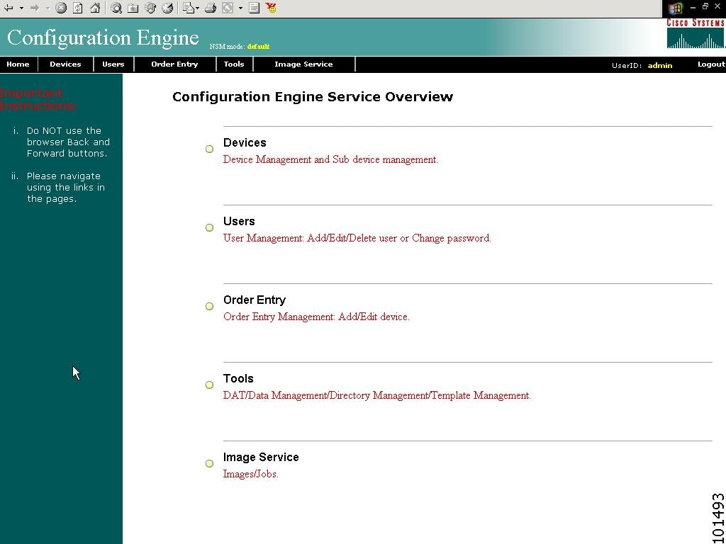
The Home page appears (see Figure 2-2).
If you have reached the Cisco CNS Configuration Engine 1.4 Home page, you have verified the successful installation on the Cisco CNS Configuration Engine 1.4.
Figure 2-1 Login Page
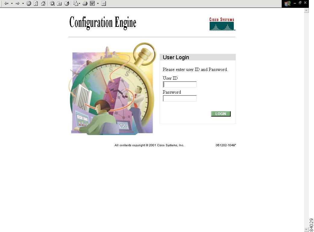
Figure 2-2 Internal Directory Mode Home Page
Reverting to Factory Setting
To revert to factory settings, follow these steps:
Step 1 ![]() Initiate a system backup.
Initiate a system backup.
Step 2 ![]() Log in to the CNS 2100 Series system as root.
Log in to the CNS 2100 Series system as root.
Use your root password.
Step 3 ![]() Type reinitialize.
Type reinitialize.
This program clears your system configuration and returns you to Setup.
Step 4 ![]() Run Setup (see "Running the Setup Program" section).
Run Setup (see "Running the Setup Program" section).
Redefining Hostname, Domain Name, and Country Code
If you want to redefine CNS 2100 Series system network information; such as hostname, domain name, and country/location code without destroying the directory data and templates, use the relocate command.
The relocate command is designed to backup and erase existing directory data so that you can redefine the CNS 2100 Series system network information using the Setup program.
To change CNS 2100 Series system network information, follow these steps:
Step 1 ![]() Log in as root.
Log in as root.
Use your root password.
Step 2 ![]() Type relocate.
Type relocate.
This program performs the same tasks as reinitialize, except that it backs up all data that you can restore when you run Setup. It also saves the configuration templates.
Step 3 ![]() Run Setup to redefine the desired system network information (see "Running the Setup Program" section).
Run Setup to redefine the desired system network information (see "Running the Setup Program" section).
Recovering Your Root Password
To recover and redefine your root password, follow these steps:
Step 1 ![]() Verify that the default account has been redefined:
Verify that the default account has been redefined:
Login: root
Password: blender
If it has, continue to Step 2 to erase the root account password.
Step 2 ![]() Restart the system by pressing the reset button and watch the output at your serial port (or VGA) console.
Restart the system by pressing the reset button and watch the output at your serial port (or VGA) console.
Step 3 ![]() At the LILO boot prompt (boot:), press the TAB key.
At the LILO boot prompt (boot:), press the TAB key.
The the name of the boot image appears.
Step 4 ![]() At the boot prompt, type:
At the boot prompt, type:
linuxserial single (or linuxvga single).
This starts you into single-user mode on your serial port (or VGA console) where you should see the prompt:
sh-2.04#
Step 5 ![]() Redefine the root password using the passwd command as follows:
Redefine the root password using the passwd command as follows:
sh-2.04 # passwd
New UNIX password:
Retype new UNIX password:
passwd: all authentication tokens updated successfully
sh-2.04#
Step 6 ![]() At the prompt sh-2.04# type:
At the prompt sh-2.04# type:
exit
This returns you to the remaining startup sequence.
Step 7 ![]() At the login prompt, login as root with the new password defined in Step 5.
At the login prompt, login as root with the new password defined in Step 5.
Installing Replacement CNS 2100 Series System
This section describes the tasks you should perform when installing a replacement CNS 2100 Series system (a new unit intended to replace an existing unit).
How to Remove the Old System
Before removing the old system:
Step 1 ![]() Initiate a system backup.
Initiate a system backup.
For information about backups, refer to your Cisco CNS Configuration Engine 1.4 Administrator Guide.
Step 2 ![]() Verify the backup data is where you expect it to be.
Verify the backup data is where you expect it to be.
Step 3 ![]() Enter the shutdown command.
Enter the shutdown command.
The system shuts down.
Step 4 ![]() Power down and remove the old system.
Power down and remove the old system.
How to Install a Replacement System
To install a replacement system, complete the following steps:
Step 1 ![]() Install and power on the new system.
Install and power on the new system.
See "Installation on Linux System."
Step 2 ![]() Run the Setup program.
Run the Setup program.
See the "Running the Setup Program" section.
Step 3 ![]() Use the configuration settings that you recorded from the old system to answer the Setup program prompts.
Use the configuration settings that you recorded from the old system to answer the Setup program prompts.
Step 4 ![]() Restore system data.
Restore system data.
For information about restore, refer to your Cisco CNS Configuration Engine 1.4 Administrator Guide.
Restarting the Cron Daemon
The time base for the CNS 2100 Series system should be set to Coordinated Universal Time (UTC). If time is changed, you must restart the cron daemon.
To restart the cron daemon, follow these steps:
Step 1 ![]() Connect to the console if you cannot connect using Telnet.
Connect to the console if you cannot connect using Telnet.
Step 2 ![]() Login to the CNS 2100 Series system as root.
Login to the CNS 2100 Series system as root.
Example:
Kernel 2.2.16-11bipsec.uid32 on an i586
login: admin
Password:
Copyright (c) 2000 Cisco Systems, Inc.
Appliance 1.0 Wed Feb 21 22:20:29 UTC 2001
Build Version (152) Wed Nov 15 12:00:13 PST 2000
bash $su
Password:
Step 3 ![]() Enter the command:
Enter the command:
# /etc/rc.d/init.d/crond restart
Example:
# /etc/rc.d/init.d/crond restart
Stopping cron daemon: [ OK ]
Starting cron daemon: [ OK ]
#
Re-imaging Your System
If the image on your hard disk has become corrupted, but the disk is operational (you can restart from the hard disk), simply reimage your system by installing the Cisco CNS Configuration Engine 1.4 CD-ROM.
Critical System Information
Before you reimage your CNS 2100 Series system, record the following information about your CNS 2100 Series system:
•![]() IP address
IP address
•![]() Gateway address
Gateway address
•![]() Network mask
Network mask
•![]() DNS name server address
DNS name server address
You need this information when you run Setup after the reimage procedure.
Initializing Tivoli Management Agent
This section describes how to:
•![]() Register and de-register the Tivoli Management Agent (TMA) to the system start and stop service
Register and de-register the Tivoli Management Agent (TMA) to the system start and stop service
•![]() Initialize the TMA
Initialize the TMA
•![]() Connect the agent to an Endpoint Gateway
Connect the agent to an Endpoint Gateway
•![]() Enable the TMA to start during system boot
Enable the TMA to start during system boot
This Linux TMA supports Tivoli Framework environment 3.7 and up.
Procedure Overview
•![]() Register Tivoli agent to system start/stop service.
Register Tivoli agent to system start/stop service.
•![]() Install the agent and attach target Endpoint Gateway
Install the agent and attach target Endpoint Gateway
Register and De-register Tivoli Agent to System Start and Stop Service
Step 1 ![]() To register the Tivoli agent start/stop script (/etc/rc.d/init.d/Tivoli_lcfd1) to system start and stop service, use the following command:
To register the Tivoli agent start/stop script (/etc/rc.d/init.d/Tivoli_lcfd1) to system start and stop service, use the following command:
chkconfig --add Tivoli_lcfd1
Once the script is registered, Tivoli agent automatically stops and starts at system restart.
Step 2 ![]() To de-register the agent from system start/stop service, use:
To de-register the agent from system start/stop service, use:
chkconfig --del Tivoli_lcfd1
Initializing the TMA
To install and initialize the agent on the system and connects it to the Endpoint Gateway passed as an argument from the command line, use the following commands:
cd /opt/Tivoli/lcf/dat/1
./lcfd.sh install -g <gateway_name>+<gw_port> -P <lcfd_port> <plus any other lcfd options>
The <lcfd_port> argument must be unique for the Endpoint Gateway environment where you are installing the agent.
Verifying TMA is Running
Step 1 ![]() From the command line, enter:
From the command line, enter:
ps -ef | grep lcf
This should return the pid and information about the running lcf process.
Step 2 ![]() From the Tivoli Desktop, validate that the agent appears in the target Gateways Endpoint list.
From the Tivoli Desktop, validate that the agent appears in the target Gateways Endpoint list.
Step 3 ![]() From the command line, enter:
From the command line, enter:
wep <endpoint_name> status
This should respond with the message:
<endpoint_name> is alive.
Enabling Telnet Following Software Installation
Telnet access is disabled following installation of the Release 1.4 software. To enable Telnet for local access only, complete these steps:
Step 1 ![]() On the CNS 2100 Series system, change directory to /etc/xinetd.d.
On the CNS 2100 Series system, change directory to /etc/xinetd.d.
Step 2 ![]() Use a text editor to operate on the telnet file as follows:
Use a text editor to operate on the telnet file as follows:
Change: disable =yes
to: disable =no
Step 3 ![]() Use the mv command to move /etc/securetty to /etc/securetty.old.
Use the mv command to move /etc/securetty to /etc/securetty.old.
Enabling IBM Director
To enable IBM Director, login as root in a terminal window, then type the following UNIX commands:
ln /etc/rc.d/init.d/init.wbem /etc/rc.d/rc3.d/S85init.wbem
ln /etc/rc.d/init.d/init.wbem /etc/rc.d/rc5.d/S85init.wbem
cp /etc/TWGagent/TWGagent.orig /etc/TWGagent/TWGagent
/etc/rc.d/init.d/init.wbem start
/etc/rc.d/init.d/TWGagent start
Cisco IOS Configuration
In order to fully support the Image Service feature of CNS Configuration Engine 1.4, the status keyword and status-url arguments for the CNS image CLI command must be specified. If they are not specified, status messages from the device are sent as events on the CNS Integration Bus. The Configuration Server does not listen to status events.
The correct syntax for the CNS image CLI command is:
cns image server http://<CNSIE-2115-K9_hostname>/cns/HttpMsgDispatcher
status http://<CNSIE-2115-K9_hostname>/cns/HttpMsgDispatcher
where:
•![]() Server and status URLs are the same
Server and status URLs are the same
•![]() Hostname variable is the hostname (not IP address) of your CNS 2100 Series system (CNSIE-2115-K9)
Hostname variable is the hostname (not IP address) of your CNS 2100 Series system (CNSIE-2115-K9)
 Feedback