Configure Point-to-Point Layer 2 Services

Point-to-point service basically emulates a transport circuit between two end nodes so the end nodes appear to be directly connected over a point-to-point link. This can be used to connect two sites.

This section introduces you to point-to-point Layer 2 services, and also describes the configuration procedures to implement it.

The following point-to-point services are supported:

  • Local Switching—A point-to-point internal circuit on a router, also known as local connect. Local switching allows switching of Layer 2 data between two attachment circuits on the same device.

  • Attachment circuit—An attachment circuit (AC) is a physical or logical port or circuit that connects a CE device to a PE device.

  • Pseudowires—A virtual point-to-point circuit from one PE router to another. Pseudowires are implemented over the MPLS network.


Note


Point-to-point Layer 2 services are also called as MPLS Layer 2 VPNs.


Pseudowire over MPLS

Table 1. Feature History Table

Feature Name

Release Information

Feature Description

Pseudowire over MPLS

Release 7.3.15

This feature allows you to tunnel two L2VPN Provider Edge (PE) devices to transport L2VPN traffic over an MPLS core network. MPLS labels are used to transport data over the pseudowire.

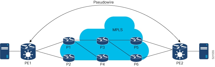
A pseudowire (PW) is a point-to-point connection between two provider edge (PE) devices which connects two attachment circuits (ACs). The two ACs connected at each PE are linked by a PW over the MPLS network, which is the MPLS PW.

PWs provide a common intermediate format to transport multiple types of network services over a Packet Switched Network (PSN) – a network that forwards packets – IPv4, IPv6, MPLS, Ethernet.

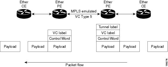
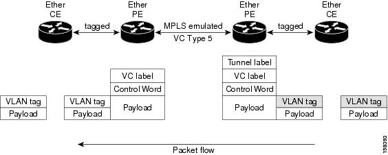
Pseudowire over MPLS or Ethernet-over-MPLS (EoMPLS) provides a tunneling mechanism for Ethernet traffic through an MPLS-enabled Layer 3 core network. PW over MPLS encapsulates Ethernet protocol data units (PDUs) using MPLS labels to forward them across the MPLS network.
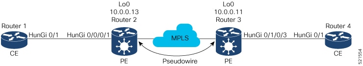
Topology

Here is an example that showcases how the L2VPN traffic is transported using the PW over MPLS network.

  • CEs are connected to PEs using the attachment circuit (AC).

  • PW is configured on the PE devices to connect two PEs over an MPLS core network.

Consider a traffic flow from Router 1 to Router 4. Router 1 sends the traffic to Router 2 through the AC. Router 2 adds the MPLS PW label and sends it to Router 3 through the PW. Each PE needs to have an MPLS label in order to reach the loopback of the remote PE. This label, usually called the Interior Gateway Protocol (IGP) label, can be learned through the MPLS Label Distribution Protocol (LDP) or MPLS Traffic Engineering (TE).

One PE advertises the MPLS label to the other PE for PW identification. Router 3 identifies traffic with MPLS label and sends it to the AC connected to Router 4 after removing the MPLS label.

You can configure static or dynamic point-to-point connections.

Configure Static Point-to-Point Connections Using Cross-Connect Circuits

This section describes how you can configure static point-to-point cross connects in a Layer 2 VPN.

Requirements and Limitations

Before you can configure a cross-connect circuit in a Layer 2 VPN, ensure that the following requirements are met:

  • The CE and PE routers are configured to operate in a network.

  • The name of a cross-connect circuit is configured to identify a pair of PE routers and must be unique within the cross-connect group.

  • A segment (an attachment circuit or pseudowire) is unique and can belong only to a single cross-connect circuit.

  • A static virtual circuit local label is globally unique and can be used in only one pseudowire.


Note


Static pseudowire connections do not use LDP for signaling.
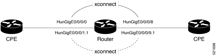

Topology

The following topology is used to configure static cross-connect circuits in a Layer 2 VPN.

Figure 1. Static Cross-Connect Circuits in a Layer 2 VPN

Configuration

/* Configure PE1 */
Router# configure 
Router(config)# l2vpn 
Router(config-l2vpn)# xconnect group XCON1
Router(config-l2vpn-xc)# p2p xc1
Router(config-l2vpn-xc-p2p)# interface HundredGigEt0/1/0/0.1
Router(config-l2vpn-xc-p2p)# neighbor 10.0.0.3 pw-id 100
Router(config-l2vpn-xc-p2p-pw)# mpls static label local 50 remote 40
Router(config-l2vpn-xc-p2p-pw)# commit
/*Configure PE2 */
Router# configure 
Router(config)# l2vpn
Router(config-l2vpn)# xconnect group XCON1
Router(config-l2vpn-xc)# p2p xc1
Router(config-l2vpn-xc-p2p)# interface HundredGigE0/2/0/0.4
Router(config-l2vpn-xc-p2p)# neighbor 10.0.0.4 pw-id 100
Router(config-l2vpn-xc-p2p-pw)# mpls static label local 40 remote 50
Router(config-l2vpn-xc-p2p-pw)# commit

Running Configuration

/* On PE1 */
!
l2vpn
 xconnect group XCON1
  p2p xc1
   interface HundredGigE0/1/0/0.1
   neighbor ipv4 10.0.0.3 pw-id 100
    mpls static label local 50 remote 40
!

/* On PE2 */
!
l2vpn
 xconnect group XCON2
  p2p xc1
   interface HundredGigE0/2/0/0.4
   neighbor ipv4 10.0.0.4 pw-id 100
    mpls static label local 40 remote 50
  !

Verification

/* Verify the static cross connect on PE1 */
Router# show l2vpn xconnect 
Tue Apr 12 20:18:02.971 IST
Legend: ST = State, UP = Up, DN = Down, AD = Admin Down, UR = Unresolved,
        SB = Standby, SR = Standby Ready, (PP) = Partially Programmed

XConnect                   Segment 1                       Segment 2                
Group      Name       ST   Description            ST       Description            ST    
------------------------   -----------------------------   -----------------------------
XCON1      xc1        UP   Hu0/1/0/0.1            UP       10.0.0.3  100    UP    
----------------------------------------------------------------------------------------

/* Verify the static cross connect on PE2 */

Router# show l2vpn xconnect 
Tue Apr 12 20:18:02.971 IST
Legend: ST = State, UP = Up, DN = Down, AD = Admin Down, UR = Unresolved,
        SB = Standby, SR = Standby Ready, (PP) = Partially Programmed

XConnect                   Segment 1                       Segment 2                
Group      Name       ST   Description            ST       Description            ST    
------------------------   -----------------------------   -----------------------------
XCON2      xc1        UP   Hu0/2/0/0.4            UP       10.0.0.4  100    UP    
----------------------------------------------------------------------------------------

Configure Dynamic Point-to-point Cross-Connects

Perform this task to configure dynamic point-to-point cross-connects.


Note


For dynamic cross-connects, LDP must be up and running.


Configuration


Router# configure 
Router(config)# l2vpn 
Router(config-l2vpn)# xconnect group vlan_grp_1
Router(config-l2vpn-xc)# p2p vlan1
Router(config-l2vpn-xc-p2p)# interface HunGigE 0/0/0/0.1
Router(config-l2vpn-xc-p2p)# neighbor 10.0.0.1 pw-id 1
Router(config-l2vpn-xc-p2p-pw)# commit

Running Configuration


configure
  l2vpn
   xconnect group vlan_grp_1
    p2p vlan1
    interface HunGigE 0/0/0/0.1
    neighbor 10.0.0.1 pw-id 1
!

PW over MPLS Supported Modes

The PW over MPLS support these modes:

Ethernet Port Mode

Table 2. Feature History Table

Feature Name

Release Information

Feature Description

Pseudowire VC Type 5

Release 7.3.15

With this feature, Ethernet port mode is supported for pseudowire over MPLS. The virtual connection (VC) type 5 is known as an Ethernet port-based PW. In this mode, both ends of a pseudowire are connected to Ethernet ports and allow a complete ethernet trunk to be transported. The ingress PE transports frames received on a main interface or subinterface. This feature nullifies the need for a dummy tag and reduces overhead. In addition, frame tagging is no longer necessary.

In Ethernet port mode, both ends of a pseudowire are connected to Ethernet ports. In this mode, the port is tunneled over the pseudowire. The ingress PE transports frames received on a main interface or after the subinterface tags are removed when the packet is received on a subinterface. The VLAN manipulation is transported over the type 5 PW, whether tagged or untagged.

This figure shows a sample ethernet port mode packet flow:

Figure 2. Ethernet Port Mode Packet Flow

Ethernet Port Mode Packet Flow

Configure Ethernet Port Mode

Perform this task to configure the Ethernet port mode.


/* PE1 configuration */
Router# configure 
Router(config)# l2vpn 
Router(config-l2vpn)# xconnect group grp1
Router(config-l2vpn-xc)# p2p xc1
Router(config-l2vpn-xc-p2p)# interface HundredGigE0/0/0/1.2
Router(config-l2vpn-xc-p2p)# neighbor 10.0.0.11 pw-id 222
Router(config-l2vpn-xc-p2p-pw)# commit

/* PE2 configuration */
Router# configure 
Router(config)# l2vpn 
Router(config-l2vpn)# xconnect group grp1
Router(config-l2vpn-xc)# p2p xc1
Router(config-l2vpn-xc-p2p)# interface HundredGigE0/1/0/3.2
Router(config-l2vpn-xc-p2p)# neighbor 10.0.0.13 pw-id 222
Router(config-l2vpn-xc-p2p-pw)# commit

Running Configuration

This section shows the Ethernet port mode running configuration.


/* PE1 configuration */
l2vpn
 xconnect group grp1
  p2p xc1
   interface HundredGigE0/0/0/1.2
   neighbor 10.0.0.11 pw-id 222

/* PE2 configuration */
l2vpn
 xconnect group grp1
  p2p xc1
   interface HundredGigE0/1/0/3.2
   neighbor 10.0.0.13 pw-id 222

Verification

Verify the Ethernet port mode configuration.

The PW type Ethernet indicates a VC type 5 PW.


Router# show l2vpn xconnect group grp1 detail
Group grp1, XC xc1, state is up; Interworking none
  AC: HundredGigE0/0/0/1.2, state is up
    Type VLAN; Num Ranges: 1
    VLAN ranges: [2, 2]
    MTU 1504; XC ID 0x840006; interworking none
    Statistics:
      packets: received 186, sent 38448
      bytes: received 12644, sent 2614356
      drops: illegal VLAN 0, illegal length 0
  PW: neighbor 10.0.0.11, PW ID 222, state is up ( established )
    PW class not set, XC ID 0xc0000004
    Encapsulation MPLS, protocol LDP
    Source address 10.0.0.13
    PW type Ethernet, control word disabled, interworking none
    PW backup disable delay 0 sec
    Sequencing not set

    PW Status TLV in use
      MPLS         Local                          Remote
      ------------ ------------------------------ -----------------------------
      Label        16026                          16031
      Group ID     0x4000280                      0x6000180
      Interface    HundredGigE0/0/0/1.2           HundredGigE0/1/0/3.2
      MTU          1504                           1504
      Control word disabled                       disabled
      PW type      Ethernet                       Ethernet
      VCCV CV type 0x2                            0x2
                   (LSP ping verification)        (LSP ping verification)
      VCCV CC type 0x6                            0x6
                   (router alert label)           (router alert label)
                   (TTL expiry)                   (TTL expiry)
      ------------ ------------------------------ -----------------------------
    Incoming Status (PW Status TLV):
      Status code: 0x0 (Up) in Notification message
    Outgoing Status (PW Status TLV):
      Status code: 0x0 (Up) in Notification message
    MIB cpwVcIndex: 3221225476
    Create time: 30/03/2021 16:30:58 (21:31:00 ago)
    Last time status changed: 30/03/2021 16:36:42 (21:25:16 ago)
    Statistics:
      packets: received 38448, sent 186
      bytes: received 2614356, sent 12644

VLAN Mode

Table 3. Feature History Table

Feature Name

Release Information

Feature Description

Pseudowire VC Type 4

Release 7.3.15

With this feature, VLAN mode is supported for pseudowire over MPLS. A virtual connection (VC) type 4 is the VLAN-based PW. The ingress PE does not remove the incoming VLAN tags that are to be transported over the PW. VC type 4 inserts an extra dummy tag with VLAN 0 onto the frame which is removed on the other side. This mode helps the service provider to segregate traffic for each customer based on the VLAN.

In VLAN mode, each VLAN on a customer-end to provider-end link can be configured as a separate L2VPN connection using virtual connection (VC) type 4. In VLAN mode, each VLAN on a customer-end to provider-end link can be configured as a separate L2VPN connection using virtual connection (VC) type 4. VLAN-based (VC Type 4) pseudowires ensure a VLAN tag is transported over the pseudowire by pushing a dummy tag at the attachment circuit ingress. If the rewrite rule pushes two or more tags, a dummy tag is not needed because these VLAN tags are transported over the pseudowire. On the remote router, the dummy tag, if added, is removed before egress.

As illustrated in the following figure, the Ethernet PE associates an internal VLAN tag to the Ethernet port for switching the traffic internally from the ingress port to the pseudowire; however, before moving traffic into the pseudowire, it removes the internal VLAN tag.

Figure 3. VLAN Mode Packet Flow

VLAN Mode Packet Flow

At the egress VLAN PE, the PE associates a VLAN tag to the frames coming out of the pseudowire, and after switching the traffic internally, it sends out the traffic on an Ethernet trunk port.


Note


Because the port is in trunk mode, the VLAN PE doesn't remove the VLAN tag and forwards the frames through the port with the added tag.


Limitation

On PW imposition PE, the pushed dummy VLAN Tag Tag Protocol Identifier (TPID) is copied from the TPID of the innermost VLAN tag popped on the ingress L2 interface where traffic is received from. If there is no VLAN tag popped on the L2 interface, the TPID on the dummy VLAN is 0x8100.

On the disposition PE, if the egress VLAN tag push is configured on the egress L2 interface, the innermost pushed VLAN tag TPID is copied from the TPID of the dummy VLAN tag. If there is no egress VLAN push configured on the egress L2 interface, the dummy VLAN tag is discarded.

Configure VLAN Mode

Perform this task to configure VLAN mode.


Router# configure
Router(config)# l2vpn
Router(config-l2vpn)# pw-class VLAN
Router(config-l2vpn-pwc)# encapsulation mpls
Router(config-l2vpn-pwc-mpls)# transport-mode vlan
Router(config-l2vpn-pwc-mpls)# exit
Router(config-l2vpn-pwc)# exit
Router(config-l2vpn)# xconnect group grp1
Router(config-l2vpn-xc)# p2p xc1
Router(config-l2vpn-xc-p2p)# neighbor 10.0.0.11 pw-id 222
Router(config-l2vpn-xc-p2p-pw)# pw-class VLAN
Router(config-l2vpn-xc-p2p-pw)# commit

Running Configuration

This section shows the VLAN mode running configuration.


l2vpn
 pw-class VLAN
  encapsulation mpls
   transport-mode vlan
  !
 !
 xconnect group grp1
  p2p xc1
   neighbor 10.0.0.11 pw-id 222
    pw-class VLAN
   !
  !
 !
!

Verification

Verify the VLAN mode configuration.

The PW type Ethernet VLAN indicates a type 4 PW.


Router# show l2vpn xconnect group grp1 detail | i " PW type"
PW type Ethernet VLAN, control word disabled, interworking none
      PW type      Ethernet VLAN                  Ethernet VLAN

VLAN Passthrough Mode

Configure the transport mode vlan passthrough command under the pw-class to negotiate a virtual connection (VC)-type 4 (Ethernet VLAN) PW, which transports whatever comes out of the AC after the VLAN tag manipulation specified by the rewrite command.The VLAN tag manipulation on the EFP ensures that there is at least one VLAN tag left on the frame because you need a VLAN tag on the frame if there are VC-type 4 PWs. No dummy tag 0 is added to the frame when you use the transport mode vlan passthrough command.

Pseudowire Redundancy

The Pseudowire Redundancy feature allows you to configure a redundant pseudowire that backs up the primary pseudowire. When the primary pseudowire fails, the PE router switches to the redundant pseudowire. You can elect to have the primary pseudowire resume operation after it becomes functional. The primary pseudowire fails when the PE router fails or when there is a network outage.

Figure 4. Pseudowire Redundancy


Forcing a Manual Switchover to the Backup Pseudowire

To force the router to switch over to the backup or switch back to the primary pseudowire, use the l2vpn switchover command in EXEC mode.

A manual switchover is made only if the peer specified in the command is actually available and the cross-connect moves to the fully active state when the command is entered.

Configure Pseudowire Redundancy

This section describes how you can configure pseudowire redundancy.

You must consider the following restrictions while configuring the Pseudowire Redundancy feature:

  • 2000 active and 2000 backup PWs are supported.

  • Only MPLS LDP is supported.

/* Configure PW on PE1 */
Router# configure 
Router(config)# l2vpn 
Router(config-l2vpn)# xconnect group XCON1
Router(config-l2vpn-xc)# p2p xc1
Router(config-l2vpn-xc-p2p)# interface HundredGigE0/1/0/0.1
Router(config-l2vpn-xc-p2p)# neighbor ipv4 172.16.0.1 pw-id 1
Router(config-l2vpn-xc-p2p-pw)# backup neighbor 192.168.0.1 pw-id 1 
Router(config-l2vpn-xc-p2p-pw-backup)# commit
/* Configure PW on PE2 */
Router# configure 
Router(config)# l2vpn 
Router(config-l2vpn)# xconnect group XCON1
Router(config-l2vpn-xc)# p2p xc1
Router(config-l2vpn-xc-p2p)# interface HundredGigE0/1/0/0.1
Router(config-l2vpn-xc-p2p)# neighbor ipv4 10.0.0.1 pw-id 1
Router(config-l2vpn-xc-p2p-pw)# commit
/* Configure PW on PE3 */
Router# configure 
Router(config)# l2vpn 
Router(config-l2vpn)# xconnect group XCON1
Router(config-l2vpn-xc)# p2p xc1
Router(config-l2vpn-xc-p2p)# interface HundredGigE0/1/0/0.1
Router(config-l2vpn-xc-p2p)# neighbor ipv4 10.0.0.1 pw-id 1
Router(config-l2vpn-xc-p2p-pw)# commit
Running Configuration
/* On PE1 */
!
l2vpn
 xconnect group XCON1
  p2p XCON1_P2P2
   interface HundredGigE 0/1/0/0.1
   neighbor ipv4 172.16.0.1 pw-id 1
    backup neighbor 192.168.0.1 pw-id 1
!

/* On PE2 */
!
l2vpn
 xconnect group XCON1
  p2p XCON1_P2P2
   interface HundredGigE 0/1/0/0.1
   neighbor ipv4 10.0.0.1 pw-id 1
    
!

/* On PE3 */
!
l2vpn
 xconnect group XCON1
  p2p XCON1_P2P2
   interface HundredGigE 0/1/0/0.1
   neighbor ipv4 10.0.0.1 pw-id 1
    
!

Verification

Verify that the configured pseudowire redundancy is up.


/* On PE1 */

Router#show l2vpn xconnect group XCON_1
Legend: ST = State, UP = Up, DN = Down, AD = Admin Down, UR = Unresolved,
        SB = Standby, SR = Standby Ready, (PP) = Partially Programmed

XConnect                   Segment 1                       Segment 2                
Group      Name       ST   Description            ST       Description            ST    
------------------------   -----------------------------   -----------------------------
XCON_1     XCON1_P2P2 UP   Hu0/1/0/0.1            UP       172.16.0.1     1000   UP    
                                                           Backup                       
                                                           192.168.0.1     1000   SB
-----------------------------------------------------------------------------------

/* On PE2 */

Router#show l2vpn xconnect group XCON_1
Tue Jan 17 15:36:12.327 UTC
Legend: ST = State, UP = Up, DN = Down, AD = Admin Down, UR = Unresolved,
        SB = Standby, SR = Standby Ready, (PP) = Partially Programmed

XConnect                   Segment 1                       Segment 2                
Group      Name       ST   Description            ST       Description            ST    
------------------------   -----------------------------   -----------------------------
XCON_1     XCON1_P2P2 UP   BE100.1                UP       10.0.0.1     1000   UP    
----------------------------------------------------------------------------------------

/* On PE3 */

Router#show l2vpn xconnect group XCON_1
Tue Jan 17 15:38:04.785 UTC
Legend: ST = State, UP = Up, DN = Down, AD = Admin Down, UR = Unresolved,
        SB = Standby, SR = Standby Ready, (PP) = Partially Programmed

XConnect                   Segment 1                       Segment 2                
Group      Name       ST   Description            ST       Description            ST    
------------------------   -----------------------------   -----------------------------
XCON_1     XCON1_P2P2 DN   BE100.1                UP       10.0.0.1     1000   SB    
----------------------------------------------------------------------------------------

Router#show l2vpn xconnect summary
Number of groups: 3950
Number of xconnects: 3950
  Up: 3950  Down: 0  Unresolved: 0 Partially-programmed: 0
  AC-PW: 3950  AC-AC: 0  PW-PW: 0 Monitor-Session-PW: 0
Number of Admin Down segments: 0
Number of MP2MP xconnects: 0
  Up 0 Down 0
  Advertised: 0 Non-Advertised: 0
Number of CE Connections: 0
  Advertised: 0 Non-Advertised: 0
Backup PW:
  Configured   : 3950
  UP           : 0
  Down         : 0
  Admin Down   : 0
  Unresolved   : 0
  Standby      : 3950
  Standby Ready: 0
Backup Interface:
  Configured   : 0
  UP           : 0
  Down         : 0
  Admin Down   : 0
  Unresolved   : 0
  Standby      : 0

Inter-AS Mode

Table 4. Feature History Table

Feature Name

Release Information

Feature Description

Inter-AS Mode for L2VPN Pseudowire

Release 7.3.15

Inter-AS is a peer-to-peer type that allows VPNs to operate through multiple providers or multi-domain networks using L2VPN cross-connect. This mode allows VPLS autodiscovery to operate across multiple BGP autonomous systems and enables service providers to offer end-to-end VPN connectivity over different geographical locations.

An autonomous system (AS) is a single network or group of networks that is controlled by a common system administration group and uses a single, clearly defined routing protocol.

As VPNs grow, their requirements expand. In some cases, VPNs need to reside on different autonomous systems in different geographic areas. In addition, some VPNs need to extend across multiple service providers (overlapping VPNs). Regardless of the complexity and location of the VPNs, the connection between autonomous systems must be seamless.

EoMPLS supports a single AS topology where the pseudowire connecting the PE routers at the two ends of the point-to-point EoMPLS cross-connects resides in the same autonomous system; or multiple AS topologies in which PE routers can reside on two different ASs using iBGP and eBGP peering.

The following figure illustrates MPLS over Inter-AS with a basic double AS topology with iBGP/LDP in each AS.

Figure 5. EoMPLS over Inter-AS: Basic Double AS Topology

Configure Inter-AS Mode

Perform this task to configure Inter-AS mode:


/* PE1 Configuration */
Router# configure
Router(config)# mpls ldp
Router(config-ldp)# router-id 10.0.0.1
Router(config-ldp)# interface HundredGigE0/2/0/3
Router(config-ldp-if)# exit
Router(config-ldp)# router bgp 100
Router(config-bgp)# bgp router-id 10.0.0.1
Router(config-bgp)# address-family l2vpn vpls-vpws
Router(config-bgp-af)# neighbor 172.16.0.1
Router(config-bgp-nbr)# remote-as 200
Router(config-bgp-nbr)# update-source Loopback0
Router(config-bgp-nbr)# address-family l2vpn vpls-vpws
Router(config-bgp-nbr-af)# exit
Router(config-bgp-nbr)# exit
Router(config-bgp)# exit
Router(config)# l2vpn
Router(config-l2vpn)# xconnect group gr1
Router(config-l2vpn-xc)# mp2mp mp1
Router(config-l2vpn-xc-mp2mp)# vpn-id 100
Router(config-l2vpn-xc-mp2mp)# l2-encapsulation vlan
Router(config-l2vpn-xc-mp2mp)# autodiscovery bgp
Router(config-l2vpn-xc-mp2mp-ad)# rd auto
Router(config-l2vpn-xc-mp2mp-ad)# route-target 2.2.2.2:100
Router(config-l2vpn-xc-mp2mp-ad)# signaling-protocol bgp
Router(config-l2vpn-xc-mp2mp-ad-sig)# ce-id 1
Router(config-l2vpn-xc-mp2mp-ad-sig-ce)# interface HunGigE0/1/0/1.1 remote-ce-id 2
Router(config-l2vpn-xc-mp2mp-ad-sig-ce)# interface HunGigE0/1/0/1.1 remote-ce-id 3
Router(config-l2vpn-xc-mp2mp-ad-sig-ce)# commit

/* PE2 Configuration */
Router# configure
Router(config)# mpls ldp
Router(config-ldp)# router-id 172.16.0.1
Router(config-ldp)# interface HundredGigE0/3/0/0
Router(config-ldp-if)# exit
Router(config-ldp)# router bgp 100
Router(config-bgp)# bgp router-id 172.16.0.1
Router(config-bgp)# address-family l2vpn vpls-vpws
Router(config-bgp-af)# neighbor 10.0.0.1
Router(config-bgp-nbr)# remote-as 100
Router(config-bgp-nbr)# update-source Loopback0
Router(config-bgp-nbr)# address-family l2vpn vpls-vpws
Router(config-bgp-nbr-af)# exit
Router(config-bgp-nbr)# exit
Router(config-bgp)# exit
Router(config)# l2vpn
Router(config-l2vpn)# xconnect group gr1
Router(config-l2vpn-xc)# mp2mp mp1
Router(config-l2vpn-xc-mp2mp)# vpn-id 100
Router(config-l2vpn-xc-mp2mp)# l2-encapsulation vlan
Router(config-l2vpn-xc-mp2mp)# autodiscovery bgp
Router(config-l2vpn-xc-mp2mp-ad)# rd auto
Router(config-l2vpn-xc-mp2mp-ad)# route-target 2.2.2.2:100
Router(config-l2vpn-xc-mp2mp-ad)# signaling-protocol bgp
Router(config-l2vpn-xc-mp2mp-ad-sig)# ce-id 2
Router(config-l2vpn-xc-mp2mp-ad-sig-ce)# interface HunGigE0/1/0/2.1 remote-ce-id 3
Router(config-l2vpn-xc-mp2mp-ad-sig-ce)# interface HunGigE0/1/0/2.2 remote-ce-id 1
Router(config-l2vpn-xc-mp2mp-ad-sig-ce)# commit
Running Configuration

This section shows the Inter-AS running configuration.


/* PE1 Configuration */
mpls ldp
 router-id 10.0.0.1
 interface HundredGigE0/2/0/3
 !
router bgp 100
 bgp router-id 10.0.0.1
 address-family l2vpn vpls-vpws
 neighbor 172.16.0.1
  remote-as 200
  update-source Loopback0
  address-family l2vpn vpls-vpws
!
l2vpn
 xconnect group gr1
  mp2mp mp1
    vpn-id 100
    l2-encapsulation vlan
    autodiscovery bgp
     rd auto
     route-target 2.2.2.2:100
     signaling-protocol bgp
      ce-id 1
       interface HunGigE0/1/0/1.1 remote-ce-id 2
       interface HunGigE0/1/0/1.2 remote-ce-id 3

/* PE2 Configuration */
mpls ldp
 router-id 172.16.0.1
 interface HundredGigE0/3/0/0
 !
router bgp 100
 bgp router-id 172.16.0.1
 address-family l2vpn vpls-vpws
 neighbor 10.0.0.1
  remote-as 100
  update-source Loopback0
  address-family l2vpn vpls-vpws
!
l2vpn
 xconnect group gr1
  mp2mp mp1
    vpn-id 100
    l2-encapsulation vlan
    autodiscovery bgp
     rd auto
     route-target 2.2.2.2:100
     signaling-protocol bgp
      ce-id 2
       interface HunGigE0/1/0/2.1 remote-ce-id 3
       interface HunGigE0/1/0/2.2 remote-ce-id 1

Preferred Tunnel Path

Table 5. Feature History Table

Feature Name

Release Information

Feature Description

VPLS over Preferred TE and MPLS OAM

Release 7.5.2

Based on your network traffic pattern, you can configure the preferred Traffic Engineering (TE) tunnel path between Provider Edge (PE) routers participating in the same Virtual Private LAN Services (VPLS). You optimize network resource utilization and performance when you set an explicit path on the PE router to direct traffic flow to a specific destination PE router.

With VPLS, you now have MPLS-OAM capabilities for troubleshooting MPLS networks:

This functionality adds the following command:

control-word

Preferred tunnel path functionality lets you map pseudowires to specific traffic-engineering tunnels. Attachment circuits are cross-connected to specific MPLS traffic engineering tunnel interfaces instead of remote PE router IP addresses (reachable using IGP or LDP). Using preferred tunnel path, it is always assumed that the traffic engineering tunnel that transports the L2 traffic runs between the two PE routers (that is, its headend starts at the imposition PE router and its tailend terminates on the disposition PE router).


Note


  • Currently, preferred tunnel path configuration applies only to MPLS encapsulation.


Configure Preferred Tunnel Path

Configuration Example


Router# configure
Router(config)# l2vpn
Router(config-l2vpn)# pw-class PATH1
Router(config-l2vpn-pwc)# encapsulation mpls
Router(config-l2vpn-pwc-mpls)# preferred-path interface tunnel-te 11 fallback disable
Router(config-l2vpn-pwc-mpls)# commit

Tunnel Configuration for VPLS

interface tunnel-te1
 ipv4 unnumbered Loopback0
 signalled-bandwidth 50
 destination 10.12.12.12
 path-option 1 explicit name FC1

L2 Configuration Example—VPLS over Preferred TE Tunnel

To configure VPLS over preferred TE tunnel, run the following commands:
RP/0/RP0/CPU0:r1(config)#interface FourHundredGigE0/0/0/0.1 l2transport
RP/0/RP0/CPU0:r1(config-subif)#encapsulation dot1q 100
RP/0/RP0/CPU0:r1(config-subif)#rewrite ingress tag pop 1 symmetric
RP/0/RP0/CPU0:r1(config-subif)#exit
RP/0/RP0/CPU0:r1(config)#l2vpn
RP/0/RP0/CPU0:r1(config)#pw-class c
RP/0/RP0/CPU0:r1(config-l2vpn-pwc)#encapsulation mpls
RP/0/RP0/CPU0:r1(config-l2vpn-pwc-mpls)#control-word
RP/0/RP0/CPU0:r1(config-l2vpn-pwc-mpls)#load-balancing
RP/0/RP0/CPU0:r1(config-l2vpn-pwc-mpls-load-bal)#flow-label both
RP/0/RP0/CPU0:r1(config-l2vpn-pwc-mpls-load-bal)#exit
RP/0/RP0/CPU0:r1(config-l2vpn-pwc-mpls)#preferred-path interface tunnel-te 1
 
RP/0/RP0/CPU0:r1(config-l2vpn-pwc-mpls)#exit
RP/0/RP0/CPU0:r1(config-l2vpn-pwc)#exit
RP/0/RP0/CPU0:r1(config-l2vpn)#bridge group bg bridge-domain bd
RP/0/RP0/CPU0:r1(config-l2vpn-bg-bd)#interface FourHundredGigE0/0/0/0.1
RP/0/RP0/CPU0:r1(config-l2vpn-bg-bd-ac)#exit
RP/0/RP0/CPU0:r1(config-l2vpn-bg-bd)#neighbor 10.12.12.12 pw-id 100
RP/0/RP0/CPU0:r1(config-l2vpn-bg-bd-pw)#pw-class c

Verification

RP/0/RP0/CPU0:r1#show l2vpn bridge-domain detail 
Wed Apr 20 17:53:26.232 UTC
Legend: pp = Partially Programmed.
Bridge group: bg, bridge-domain: bd, id: 0, state: up, ShgId: 0, MSTi: 0
  Coupled state: disabled
  VINE state: Default
  MAC learning: enabled
  MAC withdraw: enabled
    MAC withdraw for Access PW: enabled
    MAC withdraw sent on: bridge port up
    MAC withdraw relaying (access to access): disabled
  Flooding:
    Broadcast & Multicast: enabled
    Unknown unicast: enabled
  MAC aging time: 300 s, Type: inactivity
  MAC limit: 131072, Action: none, Notification: syslog
  MAC limit reached: no, threshold: 75%
  MAC port down flush: enabled
  MAC Secure: disabled, Logging: disabled
  Split Horizon Group: none
  E-Tree: Root
  Dynamic ARP Inspection: disabled, Logging: disabled
  IP Source Guard: disabled, Logging: disabled
  DHCPv4 Snooping: disabled
  DHCPv4 Snooping profile: none
  IGMP Snooping: disabled
  IGMP Snooping profile: none
  MLD Snooping profile: none
  Storm Control: disabled
  Bridge MTU: 1500
  MIB cvplsConfigIndex: 1
  Filter MAC addresses:
  P2MP PW: disabled
  Multicast Source: Not Set
  Create time: 20/04/2022 17:37:30 (00:15:55 ago)
  No status change since creation
  ACs: 1 (1 up), VFIs: 0, PWs: 1 (1 up), PBBs: 0 (0 up), VNIs: 0 (0 up)
  List of ACs:
    AC: FourHundredGigE0/0/0/0, state is up
      Type Ethernet
      MTU 1500; XC ID 0x1; interworking none
      MAC learning: enabled
      Flooding:
        Broadcast & Multicast: enabled
        Unknown unicast: enabled
      MAC aging time: 300 s, Type: inactivity
      MAC limit: 131072, Action: none, Notification: syslog
      MAC limit reached: no, threshold: 75%
      MAC port down flush: enabled
      MAC Secure: disabled, Logging: disabled
      Split Horizon Group: none
      E-Tree: Root
      Dynamic ARP Inspection: disabled, Logging: disabled
      IP Source Guard: disabled, Logging: disabled
      DHCPv4 Snooping: disabled
      DHCPv4 Snooping profile: none
      IGMP Snooping: disabled
      IGMP Snooping profile: none
      MLD Snooping profile: none
      Storm Control: bridge-domain policer
      Static MAC addresses:
      Statistics:
        packets: received 0 (multicast 0, broadcast 0, unknown unicast 0, unicast 0), sent 0
        bytes: received 0 (multicast 0, broadcast 0, unknown unicast 0, unicast 0), sent 0
        MAC move: 0
      Storm control drop counters: 
        packets: broadcast 0, multicast 0, unknown unicast 0 
        bytes: broadcast 0, multicast 0, unknown unicast 0 
      Dynamic ARP inspection drop counters: 
        packets: 0, bytes: 0
      IP source guard drop counters: 
        packets: 0, bytes: 0
      PD System Data: Learn key: 0
 List of Access PWs:
    PW: neighbor 10.12.12.12, PW ID 100, state is up ( established )
      PW class c, XC ID 0xa0000001
      Encapsulation MPLS, protocol LDP
      Source address 10.10.10.10
      PW type Ethernet, control word enabled, interworking none
      PW backup disable delay 0 sec
      Sequencing not set
      Preferred path Active : tunnel-te1, Statically configured, fallback enabled
      Ignore MTU mismatch: Disabled
      Transmit MTU zero: Disabled
      Tunnel : Up

      PW Status TLV in use
        MPLS         Local                          Remote                        
        ------------ ------------------------------ ---------------------------
        Label        24000                          24000                         
        Group ID     0x0                            0x0                           
        Interface    Access PW                      Access PW                     
        MTU          1500                           1500                          
        Control word enabled                        enabled                       
        PW type      Ethernet                       Ethernet                      
        VCCV CV type 0x2                            0x2                           
                     (LSP ping verification)        (LSP ping verification)       
        VCCV CC type 0x7                            0x7                           
                     (control word)                 (control word)                
                     (router alert label)           (router alert label)          
                     (TTL expiry)                   (TTL expiry)                  
        ------------ ------------------------------ ---------------------------
      Incoming Status (PW Status TLV):
        Status code: 0x0 (Up) in Notification message
      MIB cpwVcIndex: 2684354561
      Create time: 20/04/2022 17:37:30 (00:15:55 ago)
      Last time status changed: 20/04/2022 17:53:22 (00:00:04 ago)
      MAC withdraw messages: sent 0, received 0
      Forward-class: 0
      Static MAC addresses:
      Statistics:
        packets: received 0 (unicast 0), sent 0
        bytes: received 0 (unicast 0), sent 0
        MAC move: 0
      Storm control drop counters: 
        packets: broadcast 0, multicast 0, unknown unicast 0 
        bytes: broadcast 0, multicast 0, unknown unicast 0 
      MAC learning: enabled
      Flooding:
        Broadcast & Multicast: enabled
        Unknown unicast: enabled
      MAC aging time: 300 s, Type: inactivity
      MAC limit: 131072, Action: none, Notification: syslog
      MAC limit reached: no, threshold: 75%
      MAC port down flush: enabled
      MAC Secure: disabled, Logging: disabled
      Split Horizon Group: none
      E-Tree: Root
      DHCPv4 Snooping: disabled
      DHCPv4 Snooping profile: none
      IGMP Snooping: disabled
      IGMP Snooping profile: none
      MLD Snooping profile: none
      Storm Control: bridge-domain policer

Configure Local Switching Between Attachment Circuits

Table 6. Feature History Table

Feature Name

Release Information

Feature Description

Support of Tagged or Untagged VLAN on Physical and Bundle AC with VLAN Rewrite

Release 7.3.15

This feature supports tagged or untagged VLAN on physical and bundle interfaces. The tagged VLAN allows you to send and receive the traffic for multiple VLANs whereas, the untagged VLAN allows you to send and receive the traffic for a single VLAN. The multiple VLANs are used to differentiate traffic streams so that the traffic can be split across different services.

Local switching involves the exchange of L2 data from one attachment circuit (AC) to the other. The two ports configured in a local switching connection form an attachment circuit (AC). A local switching connection works like a bridge domain that has only two bridge ports, where traffic enters from one port of the local connection and leaves through the other.

Figure 6. Local Switching Between Attachment Circuits

These are some of the characteristics of Layer 2 local switching:

  • Because there is no bridging involved in a local connection, there is neither MAC learning nor flooding.

  • ACs in a local connection are not in the UP state if the interface state is DOWN.

  • Local switching ACs utilize a full variety of Layer 2 interfaces, including Layer 2 trunk (main) interfaces, bundle interfaces, and Ethernet Flow Points (EFPs).

  • Same-port local switching allows you to switch Layer 2 data between two circuits on the same interface.

Configuration

To configure an AC-AC point-to-point cross connect, complete the following configuration:

  • Create Layer 2 interfaces.

  • Create a cross-connect group and point-to-point connection.

  • Attach the Layer 2 interfaces to point-to-point connection.


/* Configure L2 transport and encapsulation on the VLAN sub-interfaces */
Router# configure
Router(config)# interface HunGigE 0/0/0/1.1 l2transport
Router(config-subif)# encapsulation dot1q 5 
Router(config-subif)# exit
Router(config)# interface HunGigE 0/0/0/9.1 l2transport
Router(config-subif)# encapsulation dot1q 5 
Router(config-subif)# commit


/* Configure local switching on the VLAN sub-interfaces */
Router(config)# l2vpn
Router(config-l2vpn-xc)# p2p XCON1_P2P1
Router(config-l2vpn-xc-p2p)# interface HunGigE0/0/0/1.1
Router(config-l2vpn-xc-p2p)# interface HunGigE0/0/0/9.1
Router(config-l2vpn-xc-p2p)# commit
Router(config-l2vpn-xc-p2p)# exit


Running Configuration


configure


interface HunGigE 0/0/0/1.1 l2transport
 encapsulation dot1q 5 
!
interface HunGigE 0/0/0/9.1 l2transport
  encapsulation dot1q 5 
 !


l2vpn
   p2p XCON1_P2P1
    interface HunGigE0/0/0/1.1
    interface HunGigE0/0/0/9.1
    !
   !
 !

Verification

  • Verify if the configured cross-connect is UP

    
    router# show l2vpn xconnect brief
    
    Locally Switching
    
      Like-to-Like                        UP       DOWN        UNR
    
        EFP                                1          0          0
    
        Total                              1          0          0
    
    
      Total                                1          0          0
    
    Total: 1 UP, 0 DOWN, 0 UNRESOLVED


MPLS PW Traffic Load Balancing on P Router

When an L2VPN PE needs to send a frame over an MPLS PW, the Ethernet frame is encapsulated into an MPLS frame with one or more MPLS labels; there is at least one PW label and perhaps an IGP label to reach the remote PE.

The MPLS frame is transported by the MPLS network to the remote L2VPN PE. There are typically multiple paths to reach the destination PE:

PE1 can choose between P1 and P2 as the first MPLS P router towards PE2. If P1 is selected, P1 then chooses between P3 and P4, and so on. The available paths are based on the IGP topology and the MPLS TE tunnel path.

MPLS service providers prefer to have all links equally utilized rather than one congested link with other underutilized links. This goal is not always easy to achieve because some PWs carry much more traffic than others and because the path taken by a PW traffic depends upon the hashing algorithm used in the core. Multiple high bandwidth PWs might be hashed to the same links, which creates congestion.

A very important requirement is that all packets from one flow must follow the same path. Otherwise, this leads to out-of-order frames, which might impact the quality or the performance of the applications.

Use the following methods to load balance the MPLS PW traffic:

Load Balance MPLS PW Traffic using Control-Word and Flow-Label

Table 7. Feature History Table

Feature Name

Release Information

Feature Description

Load Balance MPLS PW Traffic using Control-Word

Release 7.3.15

This feature allows the router to correctly identify the Ethernet PW packet over an IP packet, thus preventing the selection of wrong equal-cost multipath (ECMP) path for the packet that leads to the misordering of packets. This feature inserts the control word keyword immediately after the MPLS label to separate the payload from the MPLS label over a PW. The control word carries layer 2 control bits and enables sequencing.

The control-word keyword is added.

Load Balance MPLS PW Traffic using Flow-Label

Release 7.3.15

The flow-label provides the capability to identify individual flows within a pseudowire and provides routers the ability to use these flows to load balance traffic. Individual flows are determined by the hashing algorithm configured under L2VPN. Similar packets with the same source and destination addresses are all said to be in the same flow. A flow-label is created based on indivisible packet flows entering a pseudowire and is inserted as the lowermost label in the packet. Routers can use the flow-label for load balancing which provides a better traffic distribution across ECMP paths or link-bundled paths in the core.

The flow-label keyword is added.

Load balancing using Control-Word

If the MPLS packet contains the MAC address that starts with 0x4 or 0x6, a label switching router (LSR) misidentifies the Ethernet PW packet as an IP packet. The router considers that there is an IPv4 or IPv6 packet inside the MPLS packet and tries to load balance based on a hash of the source and destination IPv4 or IPv6 addresses extracted from the frame. This leads to the selection of the wrong equal-cost multipath (ECMP) path for the packet, leading to the misordering of packets.

This must not apply to an Ethernet frame that is encapsulated and transported over a PW because the destination MAC address considers the bottom label.

To overcome this issue, use the control-word keyword under a pw-class that is attached to a point-to-point PW. The control word is inserted immediately after the MPLS labels. Pseudowire over MPLS also, known as Ethernet over MPLS (EoMPLS), allows you to tunnel two L2VPN Provider Edge (PE) devices to transport L2VPN traffic over an MPLS cloud. This feature uses MPLS labels to transport data over the PW. The two L2VPN PEs are typically connected at two different sites with an MPLS core between them. This feature allows you to migrate legacy ATM and Frame Relay services to MPLS or IP core without interrupting the existing services.

Load balancing using Flow-Label

Routers typically load balance traffic based on the lowermost label in the label stack which is the same label for all flows on a given pseudowire. This can lead to asymmetric load balancing. The flow, in this context, refers to a sequence of packets that have the same source and destination pair. The packets are transported from a source provider edge (PE) to a destination PE.

The flow-label provides the capability to identify individual flows within a pseudowire and provides routers the ability to use these flows to load balance traffic. A flow-label is created based on individual packet flows entering a pseudowire and is inserted as the lowermost label in the packet. Routers can use the flow-label for load balancing which provides a better traffic distribution across ECMP paths or link-bundled paths in the core.

Topology

This example illustrates two flows distributing over ECMPs and bundle links.

Configure Load balancing using Control-Word and Flow-Label

Perform this task to configure load balancing using the control-word and flow-label .


Router# configure
Router(config)# l2vpn
Router(config-l2vpn)# pw-class path1
Router(config-l2vpn-pwc)# encapsulation mpls
Router(config-l2vpn-pwc)# control-word
Router(config-l2vpn-pwc-mpls)# load-balancing flow-label both
Router(config-l2vpn-pwc-mpls)# exit
Router(config-l2vpn-pwc)# exit
Router(config-l2vpn)# xconnect group grp1
Router(config-l2vpn-xc)# p2p vlan1
Router(config-l2vpn-xc-p2p)# interface HundredGigE0/0/0/1.2
Router(config-l2vpn-xc-p2p)# neighbor 10.0.0.2 pw-id 2000
Router(config-l2vpn-xc-p2p-pw)# pw-class path1
Router(config-l2vpn-xc-p2p-pw)# commit

Running Configuration

This section shows the running configuration.


l2vpn     
 pw-class path1
  encapsulation mpls
   control-word
   load-balancing
    flow-label both
  !       
 !        
 xconnect group grp1
  p2p vlan1
   interface HundredGigE0/0/0/1.2
   neighbor ipv4 10.0.0.2 pw-id 2000
    pw-class path1
   !      
 

L2VPN Traffic Load Balancing on PE Router

A Provider Edge (PE) router balances Layer 2 Virtual Private Network (L2VPN) traffic by efficiently distributing it across network paths based on the load balance hash.

Traffic enters the router through an L2 main interface or subinterface without MPLS labels further which the router may encapsulate this traffic with MPLS labels and forward it to L3 main interface or subinterface.

Traffic can enter the router separately through an L3 main interface or subinterface with MPLS labels if it's part of an MPLS VPN such as L2VPN.

The router parses packets to identify the required headers for generating a load balance hash, which determines the path to route the traffic across the network. For more information on the load balance hash generation process, see L2 Interfaces Load Balance Hash Generation Process and L3 Interfaces Load Balance Hash Generation Process.

Supported VLAN Tag Formats for Load Balancing

The Q100, Q200, P100, A100, and K100 hardware models support the following VLAN tag formats.

  • Untagged - The Ethernet frame doesn't carry any VLAN tag.

  • Single VLAN tag - The Ethernet frame has one 802.1Q VLAN tag.

  • Q-in-Q tagging - The Ethernet frame has two 802.1Q VLAN tag where the outer tag is a Service Provider tag (S-Tag), and the inner tag is a Customer VLAN tag (C-Tag).

  • Stacked VLAN tags - The Ethernet frame encapsulates an 802.1Q-tagged frame within another 802.1Q tag, which may include Q-in-Q but also other configurations.

The Stacked VLAN tags is supported only on Q200 based Silicon One ASIC from Release 24.1.1.

Table 8. Q100 Hardware Supported VLAN Tag Configuration

VLAN Tag

Outer Tag EtherType value

Inner Tag EtherType value

Untagged

-

-

Single VLAN tag

0x8100

-

Q-in-Q tagging

0x88A8

0x8100

Table 9. Q200 Hardware Supported VLAN Tag Configuration

VLAN Tag

Outer Tag EtherType value

Inner Tag EtherType value

Untagged

-

-

Single VLAN tag

0x8100

-

Q-in-Q tagging

0x88A8

0x8100

Stacked VLAN tags

0x8100

0x8100

The Stacked VLAN tags is supported only on Q200 based Silicon One ASIC from Release 24.1.1.

Table 10. P100, A100, and K100 Hardware Supported VLAN Tag Configuration

VLAN Tag

Outer Tag EtherType value

Inner Tag EtherType value

Untagged

-

-

Single VLAN tag

0x8100

-

Q-in-Q tagging

0x88A8

0x8100

L2 Interfaces Load Balance Hash Generation Process

L2VPN load balance depends on VLAN format in Ethernet frame.

When traffic enters the router through the L2 main interface or subinterface and

  • if the configured VLAN tag format matches the supported VLAN tag format, the router generates the load balance hash using the designated fields.

    • Source and destination MAC addresses in the Ethernet header

    • Outermost VLAN ID

    • Source and destination IP addresses of the Layer 3 header

    • Source and destination ports of the Layer 4 header

  • if the configured VLAN tag format doesn't match the supported VLAN tag format, the router generates the load balance hash using the designated fields.

    • Source and destination MAC addresses in the Ethernet frame

    • Outermost VLAN ID

If any of the designated fields are missing, the router replaces those field values with zeros.

L3 Interfaces Load Balance Hash Generation Process

The router receives L2VPN traffic with MPLS labels, applied using PW (Pseudowire) or EVPN (Ethernet VPN) labels. The router performs load balancing based on the PW and EVPN EVI (Ethernet Virtual Instance) configuration, using the flow information from the Ethernet frame behind the MPLS label.

When the L2VPN traffic with MPLS labels enters the router through the L3 main interface or subinterface and

  • if you have not enable the control-word feature and

    • if the configured VLAN tag format matches the supported VLAN tag format, the router generates the load balance hash using the designated fields.

      • Source and destination MAC addresses in the Ethernet header

      • Outermost VLAN ID

      • Source and destination IP addresses of the Layer 3 header

      • Source and destination ports of the Layer 4 header

    • if the configured VLAN tag format doesn't match the supported VLAN tag format, the router generates the load balance hash using the designated fields.

      • Source and destination MAC addresses in the Ethernet frame

      • Outermost VLAN ID

  • if you have enable the control-word feature, the router generates the load balance hash using the designated fields.

    • Destination MAC addresses in the Ethernet header

    • The first 2 bytes of the source MAC address

If any of the designated fields are missing, the router replaces those field values with zeros.

Limitations and Restrictions for L2VPN Traffic Load Balancing on PE Router

  • The router can't identify the IP header within the packet

    • if the MPLS label stack of the packet exceeds 10 layers and

    • if the IP header is beyond the tenth layer.

  • If the router can't find the IP header within the packets, it uses the Layer 2 MAC addresses and outermost VLAN ID to perform load balance operation.

  • The Stacked VLAN tags is supported only on Q200 based Silicon One ASIC from Release 24.1.1.

  • For PW to AC disposition traffic, the load balance is based on the source and destination MAC address of L2 frame carried inside PW.

  • If any of the designated fields are missing, the router replaces those field values with zeros.

G.8032 Ethernet Ring Protection Switching

Table 11. Feature History Table

Feature Name

Release Information

Feature Description

G.8032 Ethernet Ring Protection Switching

Release 24.2.11

Ethernet Ring Protection Switching (ERPS) protocol, defined in ITU-T G.8032, provides protection for Ethernet traffic in a ring topology, while ensuring that there are no loops within the ring at the Ethernet layer. The loops are prevented by blocking either a predetermined link or a failed link.

This feature introduces the ethernet ring g8032 and ethernet ring g8032 profile commands.

ERPS ensures that link or node failures recover faster in Ethernet ring topologies. During a link failure, it reroutes traffic to provide continuous connectivity, simplifies network management, and operates independently of the control planes.

Overview

Each Ethernet ring node is connected to adjacent Ethernet ring nodes participating in the Ethernet ring using two independent links. A ring link never allows the formation of loops that affect the network. The Ethernet ring uses a specific link to protect the entire Ethernet ring. This specific link is called the ring protection link (RPL). A ring link is bound by two adjacent Ethernet ring nodes and a port for a ring link (also known as a ring port).


Note


The minimum number of Ethernet ring nodes in an Ethernet ring is two.

The fundamentals of ring protection switching are:

  • The principle of loop avoidance

  • The utilization of learning, forwarding, and Filtering Database (FDB) mechanisms

Loop avoidance in an Ethernet ring is achieved by ensuring that, at any time, traffic flows on all but one of the ring links which is the RPL. Multiple nodes are used to form a ring:

  • RPL owner - It’s responsible for blocking traffic over the RPL so that no loops are formed in the Ethernet traffic. There can be only one RPL owner in a ring.

  • RPL neighbor node - The RPL neighbor node is an Ethernet ring node next to the RPL. It's responsible for blocking its end of the RPL under normal conditions. This node type is optional and prevents RPL usage when protected.

  • RPL next-neighbor node - The RPL next-neighbor node is an Ethernet ring node next to the RPL owner node or RPL neighbor node. It's used for FDB flush optimization on the ring. This node is also optional.

The following figure illustrates the G.8032 Ethernet ring.

Figure 7. G.8032 Ethernet Ring

G.8032 Ethernet Ring

Nodes on the ring use control messages called RAPS to coordinate the activities of switching on or off the RPL link. Any failure along the ring triggers a RAPS signal fail (RAPS SF) message along both directions, from the nodes next to the failed link, after the nodes have blocked the port facing the failed link. On obtaining this message, the RPL owner unblocks the RPL port.


Note


A single link failure in the ring ensures a loop-free topology.

Line status and Connectivity Fault Management protocols are used to detect ring link and node failure. During the recovery phase, when the failed link is restored, the nodes next to the restored link send RAPS no request (RAPS NR) messages. On obtaining this message, the RPL owner blocks the RPL port and sends RAPS no request, root blocked (RAPS NR, RB) messages. This causes all other nodes, other than the RPL owner in the ring, to unblock all blocked ports. The ERPS protocol is robust enough to work for both unidirectional failure and multiple link failure scenarios in a ring topology.

A G.8032 ring supports these basic operator administrative commands:

  • Force switch (FS) - Allows the operator to forcefully block a particular ring-port.

    • Effective even if there’s an existing SF condition.

    • Multiple FS commands for ring supported.

    • May be used to allow immediate maintenance operations.

  • Manual switch (MS) - Allows the operator to manually block a particular ring-port.

    • Ineffective in an existing FS or SF condition.

    • Overridden by new FS or SF conditions.

    • Multiple MS commands cancel all MS commands.

  • Clear - Cancels an existing FS or MS command on the ring-port.

    • Used (at RPL Owner) to clear non-revertive mode.

A G.8032 ring can support multiple instances. An instance is a logical ring running over a physical ring. Such instances are used for various reasons, such as load balancing VLANs over a ring. For example, odd VLANs may go in one direction of the ring, and even VLANs may go in the other direction. Specific VLANs can be configured under only one instance. They cannot overlap multiple instances. Otherwise, data traffic or RAPS packets can cross logical rings, and that isn't desirable.

G.8032 ERPS provides a new technology that relies on line status and Connectivity Fault Management (CFM) to detect link failure. By running CFM Continuity Check Messages (CCM) messages at an interval of 100ms, it's possible to achieve SONET-like switching time performance and loop free traffic.

For more information about Ethernet Connectivity Fault Management (CFM) and Ethernet Fault Detection (EFD) configuration, refer to the Configuring Ethernet OAM on the Cisco 8000 Series Router module in the Cisco 8000 Series Router Component Configuration Guide.

Timers

G.8032 ERPS specifies the use of different timers to avoid race conditions and unnecessary switching operations:

  • Delay Timers - used by the RPL Owner to verify that the network has stabilized before blocking the RPL.

    • After SF condition, a Wait-to-Restore (WTR) timer is used to verify that SF isn’t intermittent. The WTR timer can be configured by the operator, and the default time interval is 5 minutes. The time interval ranges 1–12 minutes.

    • After the FS/MS command, a Wait-to-Block timer is used to verify that no background condition exists.


    Note


    The Wait-to-Block timer may be shorter than the Wait-to-Restore timer.
  • Guard Timer - used by all nodes when changing state; it blocks latent outdated messages from causing unnecessary state changes. The Guard timer can be configured and the default time interval is 500 ms. The time interval ranges 10-2000 ms.

  • Hold-off timers - used by the underlying Ethernet layer to filter out intermittent link faults. The hold-off timer can be configured and the default time interval is 0 seconds. The time interval ranges 0–10 seconds.

    • Faults are reported to the ring protection mechanism, only if this timer expires.

During a link failure, the G8032 EPR performs either of the following operations to provide continuous connectivity:

Protection Switching during Single Link Failure

The following example describes the protection switching process during a single link failure:

For example, consider the Protection Switching during G.8032 Single Link Failure figure with the following configuration:

  • An ethernet ring is composed of seven ethernet ring nodes (A to G) with node ID (81, 26, 89, 62, 71, 31, and 75) and port ID (0 and 1).

  • The ethernet ring node A is the RPL neighbor node.

  • The ethernet ring node G is the RPL owner node.

  • The RPL is the ring link between ethernet ring nodes A and G.

  • Traffic is blocked at both ends of the RPL.

Figure 8. Protection Switching during G.8032 Single Link Failure
G-8032 Single Link Failure

The ERPS performs the following protection switching steps during a single link failure:

  1. The link operates in the normal condition.

  2. A failure occurs between ring nodes C and D.

  3. Ethernet ring nodes C and D detect a local signal failure (SF) condition and after the holdoff time interval, block the failed ring port and perform the forwarding database (FDB) flush.

  4. Ethernet ring nodes C and D start sending ring automatic protection switching (RAPS) (SF) messages periodically along with the node ID and Blocked Port Ring (BPR) pair on both ring ports, while the SF condition persists.

    For example, ring node C sends the SF(89,1) message, which consists of node ID 89 and BPR 1.

  5. All Ethernet ring nodes receiving an RAPS (SF) message perform FDB flush. When the RPL owner node G and RPL neighbor node A receive an RAPS (SF) message, the Ethernet ring node unblocks its end of the RPL and performs the FDB flush.

  6. All Ethernet ring nodes receiving a second RAPS (SF) message perform the FDB flush again; this is because of the Node ID and BPR-based mechanism.

  7. Stable SF condition—RAPS (SF) messages on the Ethernet Ring. Further RAPS (SF) messages trigger no further action.

Recovery from Single Link Failure

The following example describes the single link failure recovery process:

For example, consider the Single link failure Recovery (Revertive operation) figure with the following configuration:

  • An ethernet ring is composed of seven ethernet ring nodes (A to G) with node ID (81, 26, 89, 62, 71, 31, and 75) and port ID (0 and 1).

  • The ethernet ring node A is the RPL neighbor node.

  • The ethernet ring node G is the RPL owner node.

  • The RPL is the ring link between ethernet ring nodes A and G.

  • Traffic is blocked at both ends of the RPL.

Figure 9. Single link failure Recovery (Revertive operation)
Single link failure Recovery (Revertive operation)

The ERPS performs the following reversion steps to revertive the link during a single link failure:

  1. A failure occurs between ring nodes C and D.

  2. Recovery of link failure occurs between ring nodes C and D.

  3. Ethernet ring nodes C and D detect clearing of SF condition, start the guard timer and initiate periodical transmission of RAPS No Request (NR) messages on both ring ports.


    Note


    The guard timer prevents the reception of RAPS messages.


  4. When the Ethernet ring nodes receive an RAPS (NR) message, the node ID and BPR pair of a receiving ring port is deleted and the RPL owner node starts the WTR timer.

  5. When the guard timer expires on ethernet ring nodes C and D, they may accept the new RAPS messages that they receive. Ethernet ring node D receives an RAPS (NR) message with higher Node ID from ethernet ring node C, and unblocks its non-failed ring port.

  6. When the WTR timer expires, the RPL owner node blocks its end of the RPL, sends the RAPS (NR, RB) message with the node ID and BPR pair, and performs the FDB flush.

  7. When Ethernet ring node C receives an RAPS (NR, RB) message, it removes the block on its blocked ring ports, and stops sending RAPS (NR) messages. On the other hand, when the RPL neighbor node A receives an RAPS (NR, RB) message, it blocks its end of the RPL. In addition to this, Ethernet ring nodes A to F perform the FDB flush when receiving an RAPS (NR, RB) message, due to the existence of the Node ID and BPR based mechanism.

  8. Link operates in the stable SF condition.

Restrictions for G.8032 Ethernet Ring Protection Switching

  • You must not configure G.8032 ERPS and CFM down-mep on the same sub-interface. If you enable it, then the router displays a syslog message, as shown in the following example:

    Router# configure
    Router(config)# l2vpn
    Router(config-l2vpn)# ethernet ring g8032 test
    Router(config-l2vpn-erp)# port0 interface FourHundredGigE0/0/0/6
    Router(config-l2vpn-erp)# port1 interface FourHundredGigE0/0/0/10
    Router(config-l2vpn-erp)# instance 1
    Router(config-l2vpn-erp-inst)# profile test
    Router(config-l2vpn-erp-inst)# rpl port0 owner
    Router(config-l2vpn-erp-inst)# inclusion-list vlan-ids 1,100
    Router(config-l2vpn-erp-inst)# aps-channel
    Router(config-l2vpn-erp-inst-aps)# port0 interface FourHundredGigE0/0/0/6.1
    Router(config-l2vpn-erp-inst-aps)# port1 interface FourHundredGigE0/0/0/10.1
    
    Router(config)# interface FourHundredGigE0/0/0/6.1 l2transport
    Router(config-if)# encapsulation dot1q 1
    Router(config-if)# ethernet cfm
    Router(config-if-cfm)# mep domain domain1 service link1 mep-id 2
    
    %PLATFORM-SPITFIRE_CFM-3-G8032_VIOLATION : G8032 has been configured for interface FourHundredGigE0/0/0/6.1
    where CFM configuration exists. G8032 config is disabled.

    Instead configure the CFM down-mep on the main interface and configure the G.8032 ERPS on the sub-interface.

  • Linecards and fixed routers with Q100 and Q200 based Silicon One ASICs don't support G.8032 Ethernet Ring Protection Switching.

Configuring G.8032 Ethernet Ring Protection Switching

To configure the G.8032 operation, you have to configure ERPS and CFM separately as follows:


Note


MEP for each monitor link needs to be configured with different Maintenance Association.
  • The bridge domains to create the Layer 2 topology. The RAPS channel is configured in a dedicated management bridge domain separated from the data bridge domains.

  • Behavior characteristics, that apply to ERPS instance, if different from default values. This is optional.

This section provides information on:

Configuring ERPS Profile

Perform this task to configure the Ethernet Ring Protection Switching (ERPS) profile.

Procedure

Step 1

Configure a new G.8032 ERPS profile using the Ethernet ring g8032 profile command.

Example:
Router# configure
Router(config)# Ethernet ring g8032 profile p1

Enables G.8032 ring mode, and enters G.8032 configuration submode.

Step 2

Sets the hold-off timer using the timer command.

Example:
Router(config-g8032-ring-profile)# timer hold-off 5

Specifies a time interval (in seconds) for the guard, hold-off, and wait-to-restore timers.

The hold-off timer prevents unnecessary switching due to short-lived failures on the ring.

Step 3

Specify a non-revertive ring instance using the non-revertive command.

Example:
Router(config-g8032-ring-profile)# non-revertive
Router(config-g8032-ring-profile)# commit

This feature enables the router to use the current path until an administrator manually reverts to the original path.


Configuring an ERPS Instance

Perform this task to configure an ERPS instance.

Procedure

Step 1

Configure the layer 2 VPN with a bridge group.

Example:
Router# configure
Router(config)# l2vpn
Router(config-l2vpn)# bridge group cisco
Router(config-l2vpn-bg)# bridge-domain bd1

Creates a bridge group that can contain bridge domains, and then assigns network interfaces to the bridge domain.

Step 2

Configure a bridge domain for R-APS channels using the bridge-domain command.

Example:
Router(config-l2vpn-bg)# bridge-domain bd1

Establishes a bridge domain for R-APS channels, and enters L2VPN bridge group bridge domain configuration mode.

Step 3

Configure an interface to a bridge domain on ports 0 and 1 using the interface command.

Example:
Router(config-l2vpn-bg-bd)# interface GigabitEthernet 0/0/0/0.1
Router(config-l2vpn-bg-bd)# interface GigabitEthernet 0/0/0/1.1

Enters interface configuration mode and adds an interface to a bridge domain that allows packets to be forwarded and received from other interfaces that are part of the same bridge domain.

Step 4

Configure a bridge domain for data traffic using the bridge-domain command.

Example:
Router(config-l2vpn-bg)# bridge-domain bd2

Establishes a bridge domain for data traffic, and enters L2VPN bridge group bridge domain configuration mode.

Step 5

Configure an interface to a bridge domain using the interface command.

Example:
Router(config-l2vpn-bg-bd)# interface GigabitEthernet 0/0/0/0.10

Enters interface configuration mode and adds an interface to a bridge domain that allows packets to be forwarded and received from other interfaces that are part of the same bridge domain.

Step 6

Configure an ethernet ring using the ethernet ring g8032 command.

Example:
Router(config-l2vpn)# ethernet ring g8032 r1

Enables G.8032 ring mode, and enters G.8032 configuration submode.

Step 7

Configure an ERPS instance using the instance command.

Example:
Router(config-l2vpn-erp)# instance 1

Enters the Ethernet ring G.8032 instance configuration submode.

Step 8

Add a description for the ERPS instance that you are configuring using the description command.

Example:
Router(config-l2vpn-erp-instance)# description test

Specifies a string that serves as a description for that instance.

Step 9

Configure an ERPS profile using the profile command.

Example:
Router(config-l2vpn-erp-instance)# profile p1

Specifies associated Ethernet ring G.8032 profile.

Step 10

Specify the RPL port and designates it as a neighbor using the rpl command.

Example:
Router(config-l2vpn-erp-instance)# rpl port0 neighbor

Specifies one ring port on the local node as RPL owner, neighbor, or next-neighbor.

Step 11

Configure the VLANs that are included in the ERPS instance using the inclusion-list vlan-ids command.

Example:
Router(config-l2vpn-erp-instance)# inclusion-list vlan-ids e-g

Associates a set of VLAN IDs with the current instance.

Step 12

Enable Automatic Protection Switching (APS) channel configuration mode for the ERPS instance and sets the priority level for the APS protocol.

Example:
Router(config-l2vpn-erp-instance)# aps-channel
Router(config-l2vpn-erp-instance-aps)# level 5

Enters the ethernet ring G.8032 instance aps-channel configuration submode and specifies the APS message level. The range is 0–7.

Step 13

Assign a port to the G.8032 APS channel interface.

Example:
Router(configl2vpn-erp-instance-aps)# port0 interface GigabitEthernet 0/0/0/0.1

Associates G.8032 APS channel interface to port0.

Step 14

Assign a port to the G.8032 APS channel interface.

Example:
Router(config-l2vpn-erp-instance-aps)# port1 interface GigabitEthernet 0/0/0/1.1

Associates G.8032 APS channel interface to port1.


Configuring ERPS Parameters

Perform this task to configure ERPS parameters.

Procedure

Step 1

Configure an ethernet ring in L2VPN configuration mode.

Example:
Router# configure
Router(config)# l2vpn
Router(config-l2vpn)# ethernet ring g8032 r1

Enters L2VPN configuration mode, enables G.8032 ring mode, and enters G.8032 configuration submode.

Step 2

Enable G.8032 ERPS for the specified port (ring port).

Example:
Router(config-l2vpn-erp)# port0 interface GigabitEthernet 0/0/0/0

Step 3

Specify a port to monitor the G.8032 ERPS and detect ring link failure.

Example:
Router(config-l2vpn-erp-port0)# monitor port0 interface 0/0/0/0.5

Specifies the port that is monitored to detect ring link failure per ring port. The monitored interface must be a sub-interface of the main interface.

Step 4

Exit from port configuration submode.

Example:
Router(config-l2vpn-erp-port0)# exit

Exits port0 configuration submode.

Step 5

Enable G.8032 ERPS for the specified port (ring port).

Example:
Router(config-l2vpn-erp)# port1 interface GigabitEthernet 0/0/0/1

Enables G.8032 ERPS for the specified port (ring port).

Step 6

Specify a port to monitor the G.8032 ERPS and detect ring link failure.

Example:
Router(config-l2vpn-erp-port1)# monitor port1 interface 0/0/0/1.5

Specifies the port that is monitored to detect ring link failure per ring port. The monitored interface must be a sub-interface of the main interface.

Step 7

Exit from port configuration submode.

Example:
Router(config-l2vpn-erp-port1)# exit

Exits port1 configuration submode.

Step 8

Configure a set of VLAN IDs that isn’t protected by the Ethernet ring protection mechanism using the exclusion-list vlan-ids command.

Example:
Router(config-l2vpn-erp)# exclusion-list vlan-ids a-d

Step 9

Configure the ethernet ring G.8032 as an open ring.

Example:
Router(config-l2vpn-erp)# open-ring

Configuring TCN Propagation

Perform this task to configure topology change notification (TCN) propagation.

Procedure

Enable TCN propagation in L2VPN configuration mode.

Example:
Router# configure
Router(config)# l2vpn
Router(config-l2vpn)# tcn-propagation
Router(config-l2vpn)# commit

Enters L2VPN configuration mode and allows TCN propagation from minor ring to major ring and from MSTP to G.8032.


Configuring CFM MEP

Configuring the CFM on the main interface and G.8032 ERPS on the sub-interfaces allows you to constantly monitor the Ethernet ring's status. If a link in the ring fails, the Ethernet Fault Detection (EFD) shuts down the affected port and reroutes the traffic through the new path.

Perform the following steps to configure the CFM MEP:

Procedure

Step 1

Configure a CFM domain and service.

Example:
Router# configure
Router(config)# ethernet cfm
Router(config-cfm)# domain dom23to24 level 6
Router(config-cfm-domain)# service ser23to24 down-meps

Step 2

Configure the continuity checks.

Example:
Router(config-cfm-svc)# continuity-check interval 10s

Step 3

Configure a MEP crosscheck on the main interface to detect failures and reroute the traffic.

Example:
Router(config-cfm-svc)# mep crosscheck
Router(config-cfm-svc-xcheck)# mep-id 3
Router(config-cfm-svc-xcheck)# exit

Step 4

Configure Ethernet Fault Detection (EFD) to detect failures and reroute the traffic.

Example:
Router(config-cfm-svc)# efd

Step 5

Configure CFM MEP on the sub-interface.

Example:
Router# configure terminal
Router(config)# interface Gigabiteethernet0/0/0/0.5
Router(config-if)# ethernet cfm
Router(config-if-cfm)# mep domain dom23to24 service ser23to24 mep-id 4

For more information about Ethernet Connectivity Fault Management (CFM), refer to the Configuring Ethernet OAM on the Cisco 8000 Series Router module in the Cisco 8000 Series Router Interface and Hardware Component Configuration Guide.

Configuring G.8032 Ethernet Ring Protection Switching: Example

This sample configuration illustrates the elements that a complete G.8032 configuration includes:

# Configure the ERP profile characteristics if ERPS instance behaviors are non-default.
ethernet ring g8032 profile ERP-profile
  timer wtr 60
  timer guard 100
  timer hold-off 1 
  non-revertive
  

# Configure the ERPS instance under L2VPN
l2vpn
  ethernet ring g8032 RingA
    port0 interface g0/0/0/0
    port1 interface g0/1/0/0
    instance 1
      description BD2-ring
      profile ERP-profile
      rpl port0 owner
      vlan-ids 10-100
      aps channel 
        level 3
        port0 interface g0/0/0/0.1
        port1 interface g1/1/0/0.1 

# Set up the bridge domains
bridge group ABC
    bridge-domain BD2
      interface Gig 0/0/0/0.2
      interface Gig 0/1/0/0.2
      interface Gig 0/2/0/0.2

    bridge-domain BD2-APS
      interface Gig 0/0/0/0.1
      interface Gig 1/1/0/0.1

# EFPs configuration
interface Gig 0/0/0/0.1 l2transport
  encapsulation dot1q 5

interface Gig 1/1/0/0.1 l2transport
  encapsulation dot1q 5

interface g 0/0/0/0.2 l2transport
  encapsulation dot1q 10-100

interface g 0/1/0/0.2 l2transport
  encapsulation dot1q 10-100

interface g 0/2/0/0.2 l2transport
  encapsulation dot1q 10-100 

Configuring Interconnection Node: Example

This example shows you how to configure an interconnection node. The following figure illustrates an open ring scenario.

Figure 10. Open Ring Scenario - interconnection node

Open Ring Scenario - interconnection node

The minimum configuration required for configuring G.8032 at Router C (Open ring – Router C):

interface <ifname1.1> l2transport
	encapsulation dot1q X1
interface <ifname1.10> l2transport
	encapsulation dot1q Y1
interface <ifname2.10> l2transport
	encapsulation dot1q Y1
interface <ifname3.10> l2transport
	encapsulation dot1q Y1
l2vpn
ethernet ring g8032 <ring-name>
      port0 interface <main port ifname1>
      port1 interface none #? This router is connected to an interconnection node
      open-ring #? Mandatory when a router is part of an open-ring
      instance <1-2>
         inclusion-list vlan-ids  X1-Y1
         aps-channel
           Port0 interface <ifname1.1>
           Port1 none #? This router is connected to an interconnection node
	bridge group bg1
	   bridge-domain bd-aps#? APS-channel has its own bridge domain
	      <ifname1.1> #? There is only one APS-channel at the interconnection node
	   bridge-domain bd-traffic #? Data traffic has its own bridge domain
	      <ifname1.10>
	      <ifname2.10>
	      <ifname3.10>

Configuring the Node of an Open Ring: Example

This example shows you how to configure the node part of an open ring. The following figure illustrates an open ring scenario.

Figure 11. Open Ring Scenario

Open Ring Scenario

The minimum configuration required for configuring G.8032 at the node of the open ring (node part of the open ring at router F):

interface <ifname1.1> l2transport
	encapsulation dot1q X1
interface <ifname2.1> l2transport
	encapsulation dot1q X1
interface <ifname1.10> l2transport
	encapsulation dot1q Y1
interface <ifname2.10> l2transport
	encapsulation dot1q Y1
l2vpn
   ethernet ring g8032 <ring-name>
      port0 interface <main port ifname1>
      port1 interface <main port ifname2>
      open-ring #? Mandatory when a router is part of an open-ring
      instance <1-2>
         inclusion-list vlan-ids  X1-Y1
	     rpl port1 owner #? This node is RPL owner and <main port ifname2> is blocked
         aps-channel
           port0 interface <ifname1.1>
           port1 interface <ifname2.1>
	bridge group bg1
	   bridge-domain bd-aps#? APS-channel has its own bridge domain
	      <ifname1.1>
	      <ifname2.1>
	   bridge-domain bd-traffic #? Data traffic has its own bridge domain
	      <ifname1.10>
	      <ifname2.10>