- Cisco Unified Border Element Features Roadmap
- Overview of Cisco Unified Border Element
- Fundamental Cisco Unified Border Element Configuration
- H.323-to-H.323 Connections on a Cisco Unified Border Element
- H.323-to-SIP Connections on a Cisco Unified Border Element
- SIP-to-SIP Connections on a Cisco Unified Border Element
- Configuring Cisco Unified Border Element Videoconferencing
- Cisco Unified Border Element for H.323 Cisco Unified Communications Manager to H.323 Service Provider Connectivity
- Contents
- Prerequisites for Configuring SIP-to-SIP Connections on a Cisco Unified Border Element
- Restrictions for Configuring SIP-to-SIP Connections on a Cisco Unified Border Element
- Information About Configuring SIP-to-SIP Connections on a Cisco Unified Border Element
- How to Configure SIP-to-SIP Gateway Features
- SIP-to-SIP Basic Functionality for Session Border Controller (SBC)
- SIP-to-SIP Extended Feature Functionality for Session Border Controller (SBC)
- SIP-to-SIP Supplementary Feature Interworking for Session Border Controller (SBC)
- SIP-to-SIP Supplementary Services for Session Border Controller (SBC)
- Configuring IP Address-Hiding
- Configuring SIP-to-SIP Connections on a Cisco Unified Border Element
- Configuring Delayed-Offer to Early-Offer for SIP Audio Calls
- Configuring Call Escalation from Voice to Video
- Configuring SIP Error Message Pass Through
- Configuring Cisco UBE for Unsupported Content Pass-through
- Configuring Cisco UBE for STUN and DTLS Pass-through
- Configuring Media Flow-Around
- Prerequisites
- Configuring Media Flow-Around for a Voice Class
- Configuring Media Flow-Around at the Global Level
- Configuring Media Flow-Around for a Dial Peer
- Restrictions
- Configuring Delayed-Offer to Early-Offer Media Flow-Around at the Global Level
- Configuring Delayed-Offer to Early-Offer Media Flow-Around for a Dial-Peer
- Configuring Delayed-Offer to Early-Offer Media Flow-Around for High-Density Transcoding Calls
- Configuring Media Antitrombone
- Configuring DTMF Relay Digit-Drop on a Cisco Unified Border Element
- Configuring Support for Dynamic Payload Type Interworking for DTMF and Codec Packets for SIP-to-SIP Calls Feature
- Symmetric and Asymmetric Calls
- Prerequisites
- Restrictions
- Configuring Dynamic Payload Support at the Global Level
- Configuring Dynamic Payload Support for a Dial Peer
- Troubleshooting the Dynamic Payload Type Interworking for DTMF and Codec Packets for SIP to SIP Calls Feature
- Verifying Support for Dynamic Payload Type Interworking for DTMF and Codec Packets for SIP to SIP Calls Feature
- Enabling In-Dialog OPTIONS to Monitor Active SIP Sessions
- Configuring Cisco UBE Out-of-dialog OPTIONS Ping for Specified SIP Servers or Endpoints
- Configuring an Error Response Code upon an Out-of-Dialog OPTIONS Ping Failure
- Configuring SIP Parameters
- Configurable SIP Parameters via DHCP
- Prerequisites for Configurable SIP Parameters via DHCP
- Restrictions for Configurable SIP Parameters via DHCP
- Information About Configurable SIP Parameters via DHCP
- Cisco Unified Border Element Support for Configurable SIP Parameters via DHCP
- DHCP to Provision SIP Server, Domain Name, and Phone Number
- DHCP-SIP Call Flow
- DHCP Message Details
- How to Configure SIP Parameters via DHCP
- Configuring the DHCP Client
- Prerequisites
- Enabling the SIP Configuration
- Prerequisites
- Troubleshooting Tips
- Configuring a SIP Outbound Proxy Server
- Configuring a SIP Outbound Proxy Server in Voice Service VoIP Configuration Mode
- Configuring a SIP Outbound Proxy Server and Session Target in Dial Peer Configuration Mode
- Restrictions
- Enabling Forced Update of SIP Parameters via DHCP
- Prerequisites
- Restrictions
- SUMMARY STEPS
- Configuration Examples for Configurable SIP Parameters via DHCP
- Configuring the DHCP Client: Example
- Enabling the SIP Configuration: Example
- Configuring a SIP Outbound Proxy Server in Voice Service VoIP Configuration Mode: Example
- Configuring a SIP Outbound Proxy Server in Dial Peer Configuration Mode: Example
- Enabling Forced Update of SIP Parameters via DHCP: Example
- Configuring SIP Listening Port
- Configuring Bandwidth Parameters for SIP Calls
- Configuring Support for Session Refresh with Reinvites
- Sending a SIP Registration Message from a Cisco Unified Border Element
- Configuring Adjustable Timers for Registration Refresh and Retries
- Cisco Unified Border Element Support for SRTP-RTP Internetworking
- Prerequisites for Cisco Unified Border Element Support for SRTP-RTP Internetworking
- Restrictions for Cisco Unified Border Element Support for SRTP-RTP Internetworking
- Information About Cisco Unified Border Element Support for SRTP-RTP Internetworking
- How to Configure Cisco Unified Border Element Support for SRTP-RTP Internetworking
- Configuring Cisco Unified Border Element Support for SRTP-RTP Internetworking
- Configuring the Certificate Authority
- Configuring a Trustpoint for the Secure Universal Transcoder
- Configuring DSP Farm Services
- Associating SCCP to the Secure DSP Farm Profile
- Registering the Secure Universal Transcoder to the Cisco Unified Border Element
- Prerequisites
- Configuring SRTP-RTP Internetworking Support
- Prerequisites
- Restrictions
- Troubleshooting Tips
- Configuring Assisted Real-time Transport Control Protocol (RTCP) Report Generation
- Support for PAID, PPID, Privacy, PCPID, and PAURI Headers on the Cisco UBE
- Configuring P-Header and Random-Contact Support on the Cisco Unified Border Element
- Prerequisites
- Restrictions
- Configuring P-Header Translation on a Cisco Unified Border Element
- SUMMARY STEPS
- Configuring P-Header Translation on an Individual Dial Peer
- SUMMARY STEPS
- Configuring P-Called-Party-Id Support on a Cisco Unified Border Element
- SUMMARY STEPS
- Configuring P-Called-Party-Id Support on an Individual Dial Peer
- SUMMARY STEPS
- Configuring Privacy Support on a Cisco Unified Border Element
- SUMMARY STEPS
- Configuring Privacy Support on an Individual Dial Peer
- SUMMARY STEPS
- Configuring Random-Contact Support on a Cisco Unified Border Element
- SUMMARY STEPS
- Configuring Random-Contact Support for an Individual Dial Peer
- SUMMARY STEPS
- Support for Preloaded Routes in Outgoing INVITE Messages Based on REGISTER Information
- Configuring Support for SIP UPDATE Message per RFC 3311
- Selectively Using sip: URI or tel: URL Formats on Individual SIP Headers
- Prerequisites
- Configuring tel: URL Formats and Phone-Context Parameter
- Configuring tel: URI Formats and Phone-Context Parameter on Individual SIP Headers
- SUMMARY STEPS
- Configuring tel: URI Formats and Phone-Context Parameter on Individual SIP Headers on an Individual Dial Peer
- SUMMARY STEPS
- Configuring tel: URI Formats on the To: Header
- SUMMARY STEPS
- Configuring tel: URI Formats on the To: Header on an Individual Dial Peer
- SUMMARY STEPS
- Configuring Selective Filtering of Outgoing Provisional Response on the Cisco Unified Border Element
- Prerequisites
- Restrictions
- Configuring Selective Filtering of Outgoing Provisional Response on the Cisco Unified Border Element
- Configuring Selective Filtering of Outgoing Provisional Response on the Cisco UBE at the Global Level
- Configuring Selective Filtering of Outgoing Provisional Response on the Cisco UBE at the Dial Peer Level
- Configuring Support for Negotiation of an Audio Codec from a List of Codecs on Each Leg of a SIP-to-SIP Call on the Cisco Unified Border Element
- Benefits
- Prerequisites
- Restrictions
- Disabling Codec Filtering
- Troubleshooting Support for Negotiation of an Audio Codec from a List of Codecs on Each Leg of a SIP-to-SIP Call on the Cisco Unified Border Element
- Verifying Support for Negotiation of an Audio Codec from a List of Codecs on Each Leg of a SIP-to-SIP Call on the Cisco Unified Border Element
- Configuring Support for SIP Registration Proxy on Cisco UBE
- Configuring Support for Conditional Header Manipulation of SIP Headers
- Configuring Support for Reporting End-of-Call Statistics in SIP BYE Message
- Configuring RTP Media Loopback for SIP Calls
- Verifying and Troubleshooting SIP-to-SIP Connections on a Cisco Unified Border Element
SIP-to-SIP Connections on a Cisco Unified Border Element
This chapter describes how to configure and enable features for SIP-to-SIP connections in an Cisco Unified Border Element topology. A Cisco Unified Border Element (Cisco UBE), in this guide also called an IP-to-IP gateway (IPIPGW), border element (BE), or session border controller, facilitates connectivity between independent VoIP networks by enabling VoIP and videoconferencing calls from one IP network to another.

Activation ![]() Cisco Product Authorization Key (PAK)—A Product Authorization Key (PAK) is required to configure some of the features described in this guide. Before you start the configuration process, please register your products and activate your PAK at the following URL http://www.cisco.com/go/license.
Cisco Product Authorization Key (PAK)—A Product Authorization Key (PAK) is required to configure some of the features described in this guide. Before you start the configuration process, please register your products and activate your PAK at the following URL http://www.cisco.com/go/license.
Your software release may not support all the features documented in this module. For the latest feature information and caveats, see the release notes for your platform and software release. To find information about the features documented in this module, and to see a list of the releases in which each feature is supported, see the "Cisco Unified Border Element Features Roadmap" section.
Use Cisco Feature Navigator to find information about platform support and Cisco IOS and Catalyst OS software image support. To access Cisco Feature Navigator, go to http://www.cisco.com/go/cfn. An account on Cisco.com is not required.
For more information about Cisco IOS voice features, see the entire Cisco IOS Voice Configuration Library—including feature documents, and troubleshooting information—at http://www.cisco.com/en/US/docs/ios/12_3/vvf_c/cisco_ios_voice_configuration_library_glossary/vcl.htm.
Contents
This chapter describes how to configure SIP-to-SIP connections in a Cisco Unified Border Element (Cisco UBE). It covers the following features:
•![]() Prerequisites for Configuring SIP-to-SIP Connections on a Cisco Unified Border Element
Prerequisites for Configuring SIP-to-SIP Connections on a Cisco Unified Border Element
•![]() Restrictions for Configuring SIP-to-SIP Connections on a Cisco Unified Border Element
Restrictions for Configuring SIP-to-SIP Connections on a Cisco Unified Border Element
•![]() Information About Configuring SIP-to-SIP Connections on a Cisco Unified Border Element
Information About Configuring SIP-to-SIP Connections on a Cisco Unified Border Element
•![]() How to Configure SIP-to-SIP Gateway Features
How to Configure SIP-to-SIP Gateway Features
•![]() Configuration Examples for SIP-to-SIP Connections in a Cisco Unified Border Element
Configuration Examples for SIP-to-SIP Connections in a Cisco Unified Border Element
•![]() Feature Information for SIP-to-SIP Connections on a Cisco Unified Border Element
Feature Information for SIP-to-SIP Connections on a Cisco Unified Border Element
Prerequisites for Configuring SIP-to-SIP Connections on a Cisco Unified Border Element
•![]() Perform the prerequisites listed in the "Prerequisites for Cisco Unified Border Element Configuration" procedure in this guide.
Perform the prerequisites listed in the "Prerequisites for Cisco Unified Border Element Configuration" procedure in this guide.
•![]() Perform fundamental gateway configuration listed in the "Prerequisites for Fundamental Cisco Unified Border Element Configuration" procedure in this guide.
Perform fundamental gateway configuration listed in the "Prerequisites for Fundamental Cisco Unified Border Element Configuration" procedure in this guide.
•![]() Perform basic H.323 gateway configuration.
Perform basic H.323 gateway configuration.
•![]() Perform basic H.323 gatekeeper configuration.
Perform basic H.323 gatekeeper configuration.

Note ![]() For configuration instructions, see the "Configuring H.323 Gateways" and "Configuring H.323 Gatekeepers" chapters of the Cisco IOS Voice, Video, and Fax Configuration Guide, Release 12.2.
For configuration instructions, see the "Configuring H.323 Gateways" and "Configuring H.323 Gatekeepers" chapters of the Cisco IOS Voice, Video, and Fax Configuration Guide, Release 12.2.
Restrictions for Configuring SIP-to-SIP Connections on a Cisco Unified Border Element
Cisco IOS Release 12.4(15)XY and later releases:
•![]() Registration is not supported.
Registration is not supported.
Cisco IOS Release 12.4(15)T and before:
•![]() Delayed-Offer to Delayed-Offer is not supported.
Delayed-Offer to Delayed-Offer is not supported.
•![]() Codec T is not supported.
Codec T is not supported.
•![]() Registration is not supported.
Registration is not supported.
•![]() Supplementary services are not supported.
Supplementary services are not supported.
•![]() Transcoding is not supported.
Transcoding is not supported.
•![]() Like-to-like error messages are not passed from the incoming SIP leg to the outgoing SIP leg.
Like-to-like error messages are not passed from the incoming SIP leg to the outgoing SIP leg.
Cisco IOS Release 12.4(9)T and before:
•![]() Topology and address hiding is not supported.
Topology and address hiding is not supported.
Cisco IOS Release 12.4(9)T and later releases:
•![]() Media flow-around for Delayed-Offer to Early-Offer audio and video calls is not supported.
Media flow-around for Delayed-Offer to Early-Offer audio and video calls is not supported.
•![]() DTMF Interworking rtp-nte to out of band is not supported when high density transcoder is enabled. Use normal transcoding for rtp-nte to out of band DTMF interworking.
DTMF Interworking rtp-nte to out of band is not supported when high density transcoder is enabled. Use normal transcoding for rtp-nte to out of band DTMF interworking.
ptime attributes
•![]() SIP gateway supports one ptime attribute per media line.
SIP gateway supports one ptime attribute per media line.
•![]() Cisco UBE supports ptime attribute when one codec is offered. The ptime attribute is not sent when multiple codecs are offered by the Cico UBE.
Cisco UBE supports ptime attribute when one codec is offered. The ptime attribute is not sent when multiple codecs are offered by the Cico UBE.
•![]() The default behavior of the Cisco UBE is to select the minimum ptime value from the offer and prefer. Results are unpredictable when dissimilar networks with different packetization time periods are connected.
The default behavior of the Cisco UBE is to select the minimum ptime value from the offer and prefer. Results are unpredictable when dissimilar networks with different packetization time periods are connected.
Information About Configuring SIP-to-SIP Connections on a Cisco Unified Border Element
Note ![]() When you configure SIP on a router, the ports on all its interfaces are open by default. This makes the router vulnerable to malicious attackers who can execute toll fraud across the gateway if the router has a public IP address and a public switched telephone network (PSTN) connection. To eliminate the threat, you should bind an interface to private IP address that is not accessible by untrusted hosts. In addition, you should protect any public or untrusted interface by configuring a firewall or an access control list (ACL) to prevent unwanted traffic from traversing the router.
When you configure SIP on a router, the ports on all its interfaces are open by default. This makes the router vulnerable to malicious attackers who can execute toll fraud across the gateway if the router has a public IP address and a public switched telephone network (PSTN) connection. To eliminate the threat, you should bind an interface to private IP address that is not accessible by untrusted hosts. In addition, you should protect any public or untrusted interface by configuring a firewall or an access control list (ACL) to prevent unwanted traffic from traversing the router.
•![]() Delayed-Offer to Early-Offer audio calls are supported.
Delayed-Offer to Early-Offer audio calls are supported.
•![]() Delayed-Offer to Delayed-Offer calls are supported.
Delayed-Offer to Delayed-Offer calls are supported.
•![]() Delayed-Offer to Delayed-Offer video calls are supported in Cisco IOS Release 12.4(15)XY and later.
Delayed-Offer to Delayed-Offer video calls are supported in Cisco IOS Release 12.4(15)XY and later.
•![]() Delayed-Offer to Delayed-Offer audio calls are supported in Cisco IOS Release 12.4(15)T and later.
Delayed-Offer to Delayed-Offer audio calls are supported in Cisco IOS Release 12.4(15)T and later.
•![]() Early-Offer to Early-Offer for audio calls are supported.
Early-Offer to Early-Offer for audio calls are supported.
•![]() Early-Offer to Early-Offer, Delayed-Offer to Early-Offer video calls are supported in 12.4(15)XZ and later.
Early-Offer to Early-Offer, Delayed-Offer to Early-Offer video calls are supported in 12.4(15)XZ and later.
•![]() Fax relay is enabled by default for all systems. No further configuration is needed.
Fax relay is enabled by default for all systems. No further configuration is needed.
•![]() Like-to-like dtmf, codec and fax are supported.
Like-to-like dtmf, codec and fax are supported.
•![]() Like-to-like error messages are not passed from the incoming SIP leg to the outgoing SIP leg. Error messages are passed through Cisco Unified BE when the header-passing error-passthru command is configured in Cisco IOS Release 12.4(15) T and later.
Like-to-like error messages are not passed from the incoming SIP leg to the outgoing SIP leg. Error messages are passed through Cisco Unified BE when the header-passing error-passthru command is configured in Cisco IOS Release 12.4(15) T and later.
•![]() Media flow-around (except for Delayed-Offer to Early-Offer audio and video calls) in Cisco IOS Release 12.4(9)T and later.
Media flow-around (except for Delayed-Offer to Early-Offer audio and video calls) in Cisco IOS Release 12.4(9)T and later.
•![]() reINVITE pass-through for Session Refresh is supported.
reINVITE pass-through for Session Refresh is supported.
•![]() SIP-to-SIP Video (including Delayed-Offer to Delayed-Offer, Early-Offer to Early-Offer, Delayed-Offer to Early-Offer calls) are supported.
SIP-to-SIP Video (including Delayed-Offer to Delayed-Offer, Early-Offer to Early-Offer, Delayed-Offer to Early-Offer calls) are supported.
•![]() SRTP-to-SRTP support for SIP-to-SIP calls is supported.
SRTP-to-SRTP support for SIP-to-SIP calls is supported.
How to Configure SIP-to-SIP Gateway Features
The following section provides configuration information for the following SIP-to-SIP features.
•![]() SIP-to-SIP Basic Functionality for Session Border Controller (SBC)
SIP-to-SIP Basic Functionality for Session Border Controller (SBC)
•![]() SIP-to-SIP Extended Feature Functionality for Session Border Controller (SBC)
SIP-to-SIP Extended Feature Functionality for Session Border Controller (SBC)
•![]() SIP-to-SIP Supplementary Services for Session Border Controller (SBC)
SIP-to-SIP Supplementary Services for Session Border Controller (SBC)
•![]() SIP-to-SIP Supplementary Feature Interworking for Session Border Controller (SBC)
SIP-to-SIP Supplementary Feature Interworking for Session Border Controller (SBC)
•![]() Configuring IP Address-Hiding
Configuring IP Address-Hiding
•![]() Configuring SIP-to-SIP Connections on a Cisco Unified Border Element
Configuring SIP-to-SIP Connections on a Cisco Unified Border Element
•![]() Configuring Delayed-Offer to Early-Offer for SIP Audio Calls
Configuring Delayed-Offer to Early-Offer for SIP Audio Calls
•![]() Configuring Call Escalation from Voice to Video
Configuring Call Escalation from Voice to Video
•![]() Configuring SIP Error Message Pass Through
Configuring SIP Error Message Pass Through
•![]() Configuring Cisco UBE for Unsupported Content Pass-through
Configuring Cisco UBE for Unsupported Content Pass-through
•![]() Configuring Cisco UBE for STUN and DTLS Pass-through
Configuring Cisco UBE for STUN and DTLS Pass-through
•![]() Configuring Media Flow-Around
Configuring Media Flow-Around
•![]() Configuring Media Antitrombone
Configuring Media Antitrombone
•![]() Enabling In-Dialog OPTIONS to Monitor Active SIP Sessions
Enabling In-Dialog OPTIONS to Monitor Active SIP Sessions
•![]() Configuring Cisco UBE Out-of-dialog OPTIONS Ping for Specified SIP Servers or Endpoints
Configuring Cisco UBE Out-of-dialog OPTIONS Ping for Specified SIP Servers or Endpoints
•![]() Configuring an Error Response Code upon an Out-of-Dialog OPTIONS Ping Failure
Configuring an Error Response Code upon an Out-of-Dialog OPTIONS Ping Failure
•![]() Configurable SIP Parameters via DHCP
Configurable SIP Parameters via DHCP
•![]() Configuring SIP Listening Port
Configuring SIP Listening Port
•![]() Configuring Bandwidth Parameters for SIP Calls
Configuring Bandwidth Parameters for SIP Calls
•![]() Configuring Support for Session Refresh with Reinvites
Configuring Support for Session Refresh with Reinvites
•![]() Sending a SIP Registration Message from a Cisco Unified Border Element
Sending a SIP Registration Message from a Cisco Unified Border Element
•![]() Configuring Adjustable Timers for Registration Refresh and Retries
Configuring Adjustable Timers for Registration Refresh and Retries
•![]() Configuring Cisco Unified Border Element Support for SRTP-RTP Internetworking
Configuring Cisco Unified Border Element Support for SRTP-RTP Internetworking
•![]() Configuring Assisted Real-time Transport Control Protocol (RTCP) Report Generation
Configuring Assisted Real-time Transport Control Protocol (RTCP) Report Generation
•![]() Support for PAID, PPID, Privacy, PCPID, and PAURI Headers on the Cisco UBE
Support for PAID, PPID, Privacy, PCPID, and PAURI Headers on the Cisco UBE
•![]() Support for Preloaded Routes in Outgoing INVITE Messages Based on REGISTER Information
Support for Preloaded Routes in Outgoing INVITE Messages Based on REGISTER Information
•![]() Configuring Support for SIP UPDATE Message per RFC 3311
Configuring Support for SIP UPDATE Message per RFC 3311
•![]() Selectively Using sip: URI or tel: URL Formats on Individual SIP Headers
Selectively Using sip: URI or tel: URL Formats on Individual SIP Headers
•![]() Configuring Selective Filtering of Outgoing Provisional Response on the Cisco Unified Border Element
Configuring Selective Filtering of Outgoing Provisional Response on the Cisco Unified Border Element
•![]() Configuring Support for SIP Registration Proxy on Cisco UBE
Configuring Support for SIP Registration Proxy on Cisco UBE
•![]() Configuring Support for Conditional Header Manipulation of SIP Headers
Configuring Support for Conditional Header Manipulation of SIP Headers
•![]() Configuring Support for Reporting End-of-Call Statistics in SIP BYE Message
Configuring Support for Reporting End-of-Call Statistics in SIP BYE Message
•![]() Configuring RTP Media Loopback for SIP Calls
Configuring RTP Media Loopback for SIP Calls
•![]() Verifying and Troubleshooting SIP-to-SIP Connections on a Cisco Unified Border Element
Verifying and Troubleshooting SIP-to-SIP Connections on a Cisco Unified Border Element
SIP-to-SIP Basic Functionality for Session Border Controller (SBC)
SIP-to-SIP Basic Functionality for SBC for Cisco UBE provides termination and reorigination of both signaling and media between VoIP and video networks using SIP signaling in conformance with RFC3261. The SIP-to-SIP protocol interworking capabilities of the Cisco Unified Border Element (Cisco UBE) support the following:
•![]() Basic voice calls (Supported audio codecs include: G.711, G.729, G.728, G.726, G.723, G.722, AAC_LD, iLBC. Video codecs: H.263, and H.264)
Basic voice calls (Supported audio codecs include: G.711, G.729, G.728, G.726, G.723, G.722, AAC_LD, iLBC. Video codecs: H.263, and H.264)
•![]() Codec transcoding
Codec transcoding
•![]() Calling/called name and number
Calling/called name and number
•![]() DTMF relay interworking
DTMF relay interworking
–![]() SIP RFC 2833 <-> SIP RFC 2833
SIP RFC 2833 <-> SIP RFC 2833
–![]() SIP Notify <-> SIP Notify
SIP Notify <-> SIP Notify
•![]() Interworking between SIP early-media and SIP early-media signaling
Interworking between SIP early-media and SIP early-media signaling
•![]() Interworking between SIP delayed-media and SIP delayed-media signaling
Interworking between SIP delayed-media and SIP delayed-media signaling
•![]() RADIUS call-accounting records
RADIUS call-accounting records
•![]() RSVP synchronized with call signaling
RSVP synchronized with call signaling
•![]() SIP-SIP Video calls
SIP-SIP Video calls
•![]() TCL IVR 2.0 for SIP, including media playout and digit collection (RFC 2833 DTMF relay)
TCL IVR 2.0 for SIP, including media playout and digit collection (RFC 2833 DTMF relay)
•![]() T.38 fax relay and Cisco fax relay
T.38 fax relay and Cisco fax relay
•![]() UDP and TCP transport
UDP and TCP transport
SIP-to-SIP Extended Feature Functionality for Session Border Controller (SBC)
Enables the SIP-to-SIP functionality to conform with RFC 3261 to interoperate with SIP UAs. New SIP-to-SIP features available include:
•![]() Call Admission Control (based on CPU, memory, total calls)
Call Admission Control (based on CPU, memory, total calls)
•![]() Delayed Media Call
Delayed Media Call
•![]() ENUM support
ENUM support
•![]() Configuring SIP Error Message Pass Through
Configuring SIP Error Message Pass Through
•![]() Interoperability with Cisco Unified Communications Manager 5.0 and BroadSoft.
Interoperability with Cisco Unified Communications Manager 5.0 and BroadSoft.
•![]() Lawful Intercept
Lawful Intercept
•![]() Media Inactivity
Media Inactivity
•![]() Modem passthrough
Modem passthrough
•![]() TCP and UDP interworking
TCP and UDP interworking
•![]() Tcl scripts with SIP NOTIFY VoiceXML with SIP-to-SIP
Tcl scripts with SIP NOTIFY VoiceXML with SIP-to-SIP
•![]() Transport Layer Security (TLS)
Transport Layer Security (TLS)
SIP-to-SIP Supplementary Feature Interworking for Session Border Controller (SBC)
Provides enhanced termination and re-origination of signaling and media between VoIP and Video Networks in conformance with RFC3261. New SIP-to-SIP capabilities offered in this release on the Cisco 28xx, 38xx, 5350XM and 5400XM include:
•![]() iLBC Codec
iLBC Codec
Codecs section of the Dial Peer Configuration on Voice Gateway Routers Guide
–![]() http://www.cisco.com/en/US/docs/ios/12_3/vvf_c/dial_peer/dp_ovrvw.html
http://www.cisco.com/en/US/docs/ios/12_3/vvf_c/dial_peer/dp_ovrvw.html
Dial Peer Features and Configuration section of the Dial Peer Configuration on Voice Gateway Routers Guide
–![]() http://www.cisco.com/en/US/docs/ios/12_3/vvf_c/dial_peer/dp_confg.html
http://www.cisco.com/en/US/docs/ios/12_3/vvf_c/dial_peer/dp_confg.html
•![]() G.711 Inband DTMF to RFC 2833
G.711 Inband DTMF to RFC 2833
•![]() Session refresh
Session refresh
•![]() SIP-to-SIP Supplementary Services
SIP-to-SIP Supplementary Services
–![]() Refer/302 Based Supplementary Services Supported from 12.4(9)T onwards
Refer/302 Based Supplementary Services Supported from 12.4(9)T onwards
–![]() ReInvite Based Supplementary Services Supported from 12.4(15)XZ
ReInvite Based Supplementary Services Supported from 12.4(15)XZ
SIP-to-SIP Supplementary Services for Session Border Controller (SBC)
This chapter describes the SIP-to-SIP supplementary service features for SBC. The SIP-to-SIP supplementary services feature enhances terminating and re-originating both signaling and media between VoIP and Video networks by supporting the following features:
•![]() IP Address Hiding in all SIP messages including supplementary services
IP Address Hiding in all SIP messages including supplementary services
•![]() Media
Media
–![]() Media Flow Around
Media Flow Around
•![]() Support on Cisco AS5350XM and Cisco AS5400XM
Support on Cisco AS5350XM and Cisco AS5400XM
•![]() SIP-to-SIP Supplementary services using REFER/3xx method. The following features are enabled by default.
SIP-to-SIP Supplementary services using REFER/3xx method. The following features are enabled by default.
–![]() Message Waiting Indication
Message Waiting Indication
–![]() Call Waiting
Call Waiting
–![]() Call Transfer (Blind, Consult, Alerting)
Call Transfer (Blind, Consult, Alerting)
–![]() Call Forward (All, Busy, No Answer)
Call Forward (All, Busy, No Answer)
–![]() Distinctive Ringing
Distinctive Ringing
–![]() Call Hold/Resume
Call Hold/Resume
–![]() Music on Hold
Music on Hold
•![]() Hosted NAT Traversal for SIP
Hosted NAT Traversal for SIP
Configuring IP Address-Hiding
Configuring address-hiding hides signaling and media peer addresses from the endpoints, especially for supplemental services when the Cisco Unified BE passes REFER/3xx messages from leg to leg. Configuring the address hiding feature ensures that the Cisco Unified BE is the only point of signaling and media entry/exit in all scenarios. To enable address-hiding in all SIP messages, perform the steps in this section.
Prerequisites
To enable this feature, you must have Cisco IOS Release 12.4(9)T or a later release installed and running on your Cisco gateway. For detailed information on platform availability and subsequent releases, see the "Feature Information for SIP-to-SIP Connections on a Cisco Unified Border Element" section.
Restrictions
When supplementary services are configured the endpoint sends messages to the SBC, this is then forwarded to the peer endpoint. Address-hiding is preserved during this message forwarding
1. ![]() enable
enable
2. ![]() configure terminal
configure terminal
3. ![]() voice service voip
voice service voip
4. ![]() address-hiding
address-hiding
5. ![]() exit
exit
Configuring SIP-to-SIP Connections on a Cisco Unified Border Element
To configure SIP-to-SIP connection types, perform the steps in this section.
Prerequisites
To enable this feature, you must have Cisco IOS Release 12.3(1) or a later release installed and running on your Cisco gateway. For detailed information on platform availability and subsequent releases, see the "Feature Information for SIP-to-SIP Connections on a Cisco Unified Border Element" section.
Restrictions
•![]() Connections are disabled by default in Cisco IOS images that support the Cisco UBE.
Connections are disabled by default in Cisco IOS images that support the Cisco UBE.
•![]() This chapter covers only those features that require a unique configuration in order to support the Cisco UBE. For information on those H.323 gateway features not mentioned in this chapter, see the Cisco IOS Voice, Video, and Fax Configuration Guide.
This chapter covers only those features that require a unique configuration in order to support the Cisco UBE. For information on those H.323 gateway features not mentioned in this chapter, see the Cisco IOS Voice, Video, and Fax Configuration Guide.
1. ![]() enable
enable
2. ![]() configure terminal
configure terminal
3. ![]() voice service voip
voice service voip
4. ![]() allow-connections
allow-connections
5. ![]() exit
exit
Configuring Delayed-Offer to Early-Offer for SIP Audio Calls
This feature the alters the default configuration of the Cisco Unified BE from not distinguishing SIP Delayed-Offer to Early-Offer call flows, to forcing the Cisco Unified BE to generate an Early-Offer with the configured codecs for a incoming Delayed-Offer INVITE. To configure a Cisco Unified Border Element to send a SIP invite with Early-Offer (EO) on the Out-Leg (OL) perform the steps in this section.
Prerequisites
•![]() To enable this feature, you must have Cisco IOS Release 12.4(15)XZ or a later release installed and running on your Cisco gateway. For detailed information on platform availability and subsequent releases, see the "Feature Information for SIP-to-SIP Connections on a Cisco Unified Border Element" section.
To enable this feature, you must have Cisco IOS Release 12.4(15)XZ or a later release installed and running on your Cisco gateway. For detailed information on platform availability and subsequent releases, see the "Feature Information for SIP-to-SIP Connections on a Cisco Unified Border Element" section.
•![]() The allow-connections sip to sip command must be configured before you configure media flow-around. For more information and configuration steps see the "Configuring SIP-to-SIP Connections on a Cisco Unified Border Element" section of this chapter.
The allow-connections sip to sip command must be configured before you configure media flow-around. For more information and configuration steps see the "Configuring SIP-to-SIP Connections on a Cisco Unified Border Element" section of this chapter.
Restrictions
•![]() Cisco Unified Communications Manager 5.x supports Early-Offer over SIP trunk for audio calls with MTP
Cisco Unified Communications Manager 5.x supports Early-Offer over SIP trunk for audio calls with MTP
•![]() Support for Cisco Unified Communications Manager Early-Offer for video calls and audio calls without MTP is not supported
Support for Cisco Unified Communications Manager Early-Offer for video calls and audio calls without MTP is not supported
Table 1 shows a list of protocol interworking for SIP.
How to Configure Delayed-Offer to Early-Offer for SIP Audio Calls
To Delayed-Offer to Early-Offer for SIP Audio Calls for all VoIP calls, or individual dial peers, perform the steps in this section. This section contains the following subsections:
•![]() Configuring Delayed-Offer to Early-Offer for SIP Audio Calls at the Global Level
Configuring Delayed-Offer to Early-Offer for SIP Audio Calls at the Global Level
•![]() Configuring Delayed-Offer to Early-Offer for SIP Audio Calls for a Dial-Peer
Configuring Delayed-Offer to Early-Offer for SIP Audio Calls for a Dial-Peer
Configuring Delayed-Offer to Early-Offer for SIP Audio Calls at the Global Level
To configure Delayed-Offer to Early-Offer for SIP Audio Calls at the global level, perform the steps in this section.
SUMMARY STEPS
1. ![]() enable
enable
2. ![]() configure terminal
configure terminal
3. ![]() voice service voip
voice service voip
4. ![]() allow-connections sip
allow-connections sip
5. ![]() early-offer forced
early-offer forced
6. ![]() exit
exit
Configuring Delayed-Offer to Early-Offer for SIP Audio Calls for a Dial-Peer
To configure Delayed-Offer to Early-Offer for SIP Audio Calls for an individual dial-peer, perform the steps in this section.
SUMMARY STEPS
1. ![]() enable
enable
2. ![]() configure terminal
configure terminal
3. ![]() dial-peer voice 1 voip
dial-peer voice 1 voip
4. ![]() voice-class sip early-offer forced
voice-class sip early-offer forced
5. ![]() exit
exit
Configuring Call Escalation from Voice to Video
The Call Escalation from Voice to Video feature supports mid-call escalation of SIP-to-SIP calls via signaling from voice calls to video. The call initially starts as an audio-only call. When the call is in progress, media renegotiation results in a video stream being added to the call, leading to call escalation from an audio-only call to an audio and video call.
To configure call escalation for SIP-to-SIP calls from voice calls to video, perform the following task.
SUMMARY STEPS
1. ![]() enable
enable
2. ![]() configure terminal
configure terminal
3. ![]() voice service voip
voice service voip
4. ![]() allow-connections from-type to to-type
allow-connections from-type to to-type
5. ![]() exit
exit
6. ![]() dial-peer voice tag voip
dial-peer voice tag voip
7. ![]() session protocol sipv2
session protocol sipv2
8. ![]() codec transparent
codec transparent
9. ![]() end
end
Configuring SIP Error Message Pass Through
The SIP error message pass through feature allows a received error response from one SIP leg to pass transparently over to another SIP leg. This functionality will pass SIP error responses that are not yet supported on the Cisco UBE or will preserve the Q.850 cause code across two sip call-legs.
SIP error responses that are not supported on the Cisco UBE include: 300—Multiple choices, 301—Moved permanently, and 485—Ambiguous
Pre-leg SIP error responses that are not transparently passed though include:
Prerequisites
To enable this feature, you must have Cisco IOS Release XXX or a later release installed and running on your Cisco gateway. For detailed information on platform availability and subsequent releases, see the "Feature Information for SIP-to-SIP Connections on a Cisco Unified Border Element" section.
Restrictions
•![]() Configuring SIP error header passing in at the dial-peer level is not supported.
Configuring SIP error header passing in at the dial-peer level is not supported.
SUMMARY STEPS
1. ![]() enable
enable
2. ![]() configure terminal
configure terminal
3. ![]() voice service voice
voice service voice
4. ![]() sip
sip
5. ![]() header-passing error-pass through
header-passing error-pass through
6. ![]() exit
exit
Configuring Cisco UBE for Unsupported Content Pass-through
This feature introduces the ability to configure the Cisco UBE to pass through end to end headers at a global or dial-peer level, that are not processed or understood in a SIP trunk to SIP trunk scenario. The pass through functionality includes all or only a configured list of unsupported or non-mandatory SIP headers, and all unsupported content/MIME types.
The Cisco Unified Border Element does not support end-to-end media negotiation between the two endpoints that establish a call session through the Cisco Unified Border Element. This is a limitation when the endpoints intend to negotiate codec/payload types that the Cisco Unified Border Element does not process, because currently, unsupported payload types will never be negotiated by the Cisco Unified Border Element. Unsupported content types include text/plain, image/jpeg and application/resource-lists+xml. To address this problem, SDP is configured to pass through transparently at the Cisco Unified Border Element, so that both the remote ends can negotiate media independently of the Cisco Unified Border Element.
SDP pass-through is addressed in two modes:
•![]() Flow-through: Cisco Unified Border Element plays no role in the media negotiation, it blindly terminates and re-originates the RTP packets irrespective of the content type negotiated by both the ends. This supports address hiding and NAT traversal.
Flow-through: Cisco Unified Border Element plays no role in the media negotiation, it blindly terminates and re-originates the RTP packets irrespective of the content type negotiated by both the ends. This supports address hiding and NAT traversal.
•![]() Flow-around: Cisco Unified Border Element neither plays a part in media negotiation, nor does it terminate and re-originate media. Media negotiation and media exchange is completely end-to-end.
Flow-around: Cisco Unified Border Element neither plays a part in media negotiation, nor does it terminate and re-originate media. Media negotiation and media exchange is completely end-to-end.
Prerequisites for Cisco UBE for Unsupported Content Pass-through
•![]() To enable this feature, you must have Cisco IOS Release XXX or a later release installed and running on your Cisco gateway. For detailed information on platform availability and subsequent releases, see the "Feature Information for SIP-to-SIP Connections on a Cisco Unified Border Element" section.
To enable this feature, you must have Cisco IOS Release XXX or a later release installed and running on your Cisco gateway. For detailed information on platform availability and subsequent releases, see the "Feature Information for SIP-to-SIP Connections on a Cisco Unified Border Element" section.
•![]() Configuring the media flow-around command is required for SDP pass-through. When flow-around is not configured, the flow-through mode of SDP pass-through will be functional.
Configuring the media flow-around command is required for SDP pass-through. When flow-around is not configured, the flow-through mode of SDP pass-through will be functional.
•![]() When the dial-peer media flow mode is asymmetrically configured, the default behavior is to fallback to SDP pass-through with flow-through.
When the dial-peer media flow mode is asymmetrically configured, the default behavior is to fallback to SDP pass-through with flow-through.
Restrictions for Cisco UBE for Unsupported Content Pass-through
When SDP pass-through is enabled, some of interworking that the Cisco Unified Border Element currently performs cannot be activated. These features include:
•![]() Delayed Offer to Early Offer Interworking
Delayed Offer to Early Offer Interworking
•![]() Supplementary Services with triggered Invites
Supplementary Services with triggered Invites
•![]() DTMF Interworking scenarios
DTMF Interworking scenarios
•![]() Fax Interworking/QoS Negotiation
Fax Interworking/QoS Negotiation
•![]() Transcoding
Transcoding
To enable Cisco UBE Unsupported Content Pass-through perform the steps in this section. This section contains the following subsections:
•![]() Configuring Cisco UBE for Unsupported Content Pass-through at the Global Level
Configuring Cisco UBE for Unsupported Content Pass-through at the Global Level
•![]() Configuring Cisco UBE for Unsupported Content Pass-through at the Dial Peer Level
Configuring Cisco UBE for Unsupported Content Pass-through at the Dial Peer Level
Configuring Cisco UBE for Unsupported Content Pass-through at the Global Level
To configure Unsupported Content Pass-through on an Cisco Unified Border Element at the global level, perform the steps in this section.
SUMMARY STEPS
1. ![]() enable
enable
2. ![]() configure terminal
configure terminal
3. ![]() voice service voip
voice service voip
4. ![]() sip
sip
5. ![]() pass-thru {content {sdp | unsupp} | headers {unsupp | list tag}}
pass-thru {content {sdp | unsupp} | headers {unsupp | list tag}}
6. ![]() exit
exit
Configuring Cisco UBE for Unsupported Content Pass-through at the Dial Peer Level
To configure Unsupported Content Pass-through on an Cisco Unified Border Element at the dial-peer level, perform the steps in this section.
SUMMARY STEPS
1. ![]() enable
enable
2. ![]() configure terminal
configure terminal
3. ![]() dial-peer voice number voip
dial-peer voice number voip
4. ![]() voice-class sip pass-thru{{headers | content} {content {unsupp | sdp}}
voice-class sip pass-thru{{headers | content} {content {unsupp | sdp}}
5. ![]() exit
exit
Configuring Cisco UBE for STUN and DTLS Pass-through
Cisco TelePresence System (CTS) endpoints send and receive Session Traversal Utilities for NAT (STUN) and Datagram Transport Layer Security (DTLS) packets. STUN packets are sent to open and refresh firewall pinholes. DTLS handshakes are performed to establish the Secure Real-Time Transport Protocol (SRTP) security parameters for secure CTS calls.
This feature enables Cisco Unified Border Element (Cisco UBE) to support STUN and DTLS packet pass-through, thereby adding support for secure CTS calls through Cisco UBE. However, the feature is generic and is supported for any endpoint that sends STUN or DTLS packets, including Trusted Relay Point (TRP).
Note ![]() The configuration for STUN and DTLS pass-through on Cisco UBE is enabled by default and requires no specific configuration.
The configuration for STUN and DTLS pass-through on Cisco UBE is enabled by default and requires no specific configuration.
However, to enable STUN and DTLS pass-through for Cisco TelePresence System (CTS) calls, perform the following tasks:
•![]() Configuring RTCP Report Generation on Cisco UBE (optional)
Configuring RTCP Report Generation on Cisco UBE (optional)
•![]() Troubleshooting Tips (optional)
Troubleshooting Tips (optional)
Restrictions
•![]() STUN and DTLS pass-through over IPv6 is not supported.
STUN and DTLS pass-through over IPv6 is not supported.
•![]() DTLS pass-through is not supported for T.38 fax and modem relay calls.
DTLS pass-through is not supported for T.38 fax and modem relay calls.
•![]() STUN and DTLS pass-through is not supported when Cisco UBE inserts a Digital Signal Processor (DSP) for transcoding interworkings such as SRTP-RTP, dual-tone multi-frequency (DTMF), and so on.
STUN and DTLS pass-through is not supported when Cisco UBE inserts a Digital Signal Processor (DSP) for transcoding interworkings such as SRTP-RTP, dual-tone multi-frequency (DTMF), and so on.
Configuring STUN and DTLS Pass-through for CTS Calls at the Global Level
Perform this task to configure STUN and DTLS pass-through for CTS calls at the global level.
SUMMARY STEPS
1. ![]() enable
enable
2. ![]() configure terminal
configure terminal
3. ![]() voice service voip
voice service voip
4. ![]() rtp-ssrc multiplex
rtp-ssrc multiplex
5. ![]() allow-connections from-type to to-type
allow-connections from-type to to-type
6. ![]() sip
sip
7. ![]() rel1xx disable
rel1xx disable
8. ![]() header-passing error-passthru
header-passing error-passthru
9. ![]() end
end
DETAILED STEPS
Configuring STUN and DTLS Pass-through for CTS Calls at the Dial Peer Level
Perform this task to configure STUN and DTLS pass-through for CTS calls at the dial-peer level.
SUMMARY STEPS
1. ![]() enable
enable
2. ![]() configure terminal
configure terminal
3. ![]() dial-peer voice voice-dial-peer-tag voip
dial-peer voice voice-dial-peer-tag voip
4. ![]() destination-pattern E.164-standard-number
destination-pattern E.164-standard-number
5. ![]() rtp payload-type cisco-codec-fax-ind number
rtp payload-type cisco-codec-fax-ind number
6. ![]() rtp payload-type cisco-codec-aacld number
rtp payload-type cisco-codec-aacld number
7. ![]() rtp payload-type cisco-codec-video-h264 number
rtp payload-type cisco-codec-video-h264 number
8. ![]() session protocol sipv2
session protocol sipv2
9. ![]() session target ipv4:destination-address
session target ipv4:destination-address
10. ![]() incoming called-number E.164-standard-number
incoming called-number E.164-standard-number
11. ![]() playout-delay minimum low
playout-delay minimum low
12. ![]() codec transparent
codec transparent
13. ![]() no vad
no vad
14. ![]() end
end
DETAILED STEPS
Troubleshooting Tips
The following debug commands display the details about STUN and DTLS packets sent and received:
•![]() debug ccsip messages—Shows SIP messages.
debug ccsip messages—Shows SIP messages.
Router# debug ccsip messages
SIP Call messages tracing is enabled
•![]() debug ccsip error—Shows SIP Service Provider Interface (SPI) errors.
debug ccsip error—Shows SIP Service Provider Interface (SPI) errors.
Router# debug ccsip error
SIP Call error tracing is enabled
•![]() debug voip rtp session event—Shows debugging related to RTP named event packets.
debug voip rtp session event—Shows debugging related to RTP named event packets.
Router# debug voip rtp session event
*Nov 26 12:10:06.558: voip_rtp_is_media_service_pak: Received DTLS packet
(src ip=192.16.2.2, src port=19312, dst ip=192.16.2.1, dst port=16386
pdu size=111, pdu=0x16, switching ctx=interrupt)
*Nov 26 12:10:06.558: voip_rtp_send_service_pak: Sending DTLS packet
(src ip=192.16.2.1, src port=17958, dst ip=192.16.2.3, dst port=5020
pdu size=111, pdu=0x16, switching ctx=interrupt)
*Nov 26 12:10:07.014: voip_rtp_is_media_service_pak: Received STUN packet
(src ip=192.16.2.2, src port=19210, dst ip=192.16.2.1, dst port=16910
pdu size=20, pdu=0x00, switching ctx=interrupt)
*Nov 26 12:10:07.014: voip_rtp_send_service_pak: Sending STUN packet
(src ip=192.16.2.1, src port=17894, dst ip=192.16.2.3, dst port=5022
pdu size=20, pdu=0x00, switching ctx=interrupt)
Note ![]() The debug voip rtp session event command should be enabled only for troubleshooting purposes.
The debug voip rtp session event command should be enabled only for troubleshooting purposes.
Configuring Media Flow-Around
This feature adds media flow-around capability on the Cisco Unified Border Element by supporting the processing of call setup and teardown requests (VoIP call signaling) and for media streams (flow-through and flow-around). Media flow-around can be configured the global level or it must be configured on both incoming and outgoing dial peers. If configured only on either the incoming or outgoing dialpeer, the call will become a flow-through call.
Media flow-around is a good choice to improve scalability and performance when network-topology hiding and bearer-level interworking features are not required
With the default configuration, the Cisco UBE receives media packets from the inbound call leg, terminates them, and then reoriginates the media stream on an outbound call leg. Media flow-around enables media packets to be passed directly between the endpoints, without the intervention of the Cisco UBE. The Cisco UBE continues to handle routing and billing functions.
To specify media flow-around for voice class, all VoIP calls, or individual dial peers, perform the steps in this section. This section contains the following subsections:
•![]() Configuring Media Flow-Around for a Voice Class
Configuring Media Flow-Around for a Voice Class
•![]() Configuring Media Flow-Around at the Global Level
Configuring Media Flow-Around at the Global Level
•![]() Configuring Media Flow-Around for a Dial Peer
Configuring Media Flow-Around for a Dial Peer
•![]() Configuring Delayed-Offer to Early-Offer Media Flow-Around at the Global Level
Configuring Delayed-Offer to Early-Offer Media Flow-Around at the Global Level
•![]() Configuring Delayed-Offer to Early-Offer Media Flow-Around for a Dial-Peer
Configuring Delayed-Offer to Early-Offer Media Flow-Around for a Dial-Peer
•![]() Configuring Delayed-Offer to Early-Offer Media Flow-Around for High-Density Transcoding Calls
Configuring Delayed-Offer to Early-Offer Media Flow-Around for High-Density Transcoding Calls
Prerequisites
•![]() To enable this feature, you must have Cisco IOS Release XXX or a later release installed and running on your Cisco gateway. For detailed information on platform availability and subsequent releases, see the "Feature Information for SIP-to-SIP Connections on a Cisco Unified Border Element" section.
To enable this feature, you must have Cisco IOS Release XXX or a later release installed and running on your Cisco gateway. For detailed information on platform availability and subsequent releases, see the "Feature Information for SIP-to-SIP Connections on a Cisco Unified Border Element" section.
•![]() The allow-connections sip to sip command must be configured before you configure media flow-around. For more information and configuration steps see the "Configuring SIP-to-SIP Connections on a Cisco Unified Border Element" section of this chapter.
The allow-connections sip to sip command must be configured before you configure media flow-around. For more information and configuration steps see the "Configuring SIP-to-SIP Connections on a Cisco Unified Border Element" section of this chapter.
Configuring Media Flow-Around for a Voice Class
To configure media flow-around for a voice class, perform the steps in this section.
SUMMARY STEPS
1. ![]() enable
enable
2. ![]() configure terminal
configure terminal
3. ![]() voice class media 1
voice class media 1
4. ![]() media flow-around
media flow-around
5. ![]() dial-peer voice 2 voip
dial-peer voice 2 voip
6. ![]() voice-class media 1
voice-class media 1
7. ![]() exit
exit
Configuring Media Flow-Around at the Global Level
To configure media flow-around at the global level, perform the steps in this section.
SUMMARY STEPS
1. ![]() enable
enable
2. ![]() configure terminal
configure terminal
3. ![]() voice service voip
voice service voip
4. ![]() media flow-around
media flow-around
5. ![]() exit
exit
Configuring Media Flow-Around for a Dial Peer
To configure media flow-around for an individual dial peer, perform the steps in this section.
Restrictions
If you plan to configure both incoming and outgoing dial peers, you must specify the transparent codec on the incoming dial peer.
SUMMARY STEPS
1. ![]() enable
enable
2. ![]() configure terminal
configure terminal
3. ![]() dial-peer voice number voip
dial-peer voice number voip
4. ![]() media flow-around
media flow-around
5. ![]() exit
exit
Configuring Delayed-Offer to Early-Offer Media Flow-Around at the Global Level
Perform this task to configure delayed-offer (DO) to early-offer (EO) media flow-around at the voice service configuration mode.
SUMMARY STEPS
1. ![]() enable
enable
2. ![]() configure terminal
configure terminal
3. ![]() voice service voip
voice service voip
4. ![]() media flow-around
media flow-around
5. ![]() sip
sip
6. ![]() early-offer forced
early-offer forced
7. ![]() exit
exit
8. ![]() exit
exit
9. ![]() exit
exit
Configuring Delayed-Offer to Early-Offer Media Flow-Around for a Dial-Peer
Perform this task to configure DO to EO Media Flow-Around for an individual dial peer.
SUMMARY STEPS
1. ![]() enable
enable
2. ![]() configure terminal
configure terminal
3. ![]() dial-peer voice number voip
dial-peer voice number voip
4. ![]() media flow-around
media flow-around
5. ![]() voice class sip early-offer forced
voice class sip early-offer forced
6. ![]() exit
exit
7. ![]() exit
exit
Configuring Delayed-Offer to Early-Offer Media Flow-Around for High-Density Transcoding Calls
Perform this task to configure Delayed-Offer to Early-Offer Media transcoding high-density calls.
SUMMARY STEPS
1. ![]() enable
enable
2. ![]() configure terminal
configure terminal
3. ![]() voice service voip
voice service voip
4. ![]() media transcoder high-density
media transcoder high-density
5. ![]() sip
sip
6. ![]() early offer-forced
early offer-forced
7. ![]() exit
exit
8. ![]() exit
exit
9. ![]() exit
exit
Configuring Media Antitrombone
Media Trombones are media loops in a SIP entity due to call transfer or call forward. Media loops in Cisco UBE are not detected because Cisco UBE looks at both call types as individual calls and not calls related to each other.
Antitromboning is a media signaling service in SIP entity to overcome the media loops. Antitrombone service has to be enabled only when no media interworking is required in both the out-legs.
To specify media antitrombone for voice class, all VoIP calls, or individual dial peers, perform the tasks in the following sections:
•![]() Configuring Media Antitrombone for a Voice Class (Required)
Configuring Media Antitrombone for a Voice Class (Required)
•![]() Configuring Media Antritrombone at the Global Level (Required)
Configuring Media Antritrombone at the Global Level (Required)
•![]() Configuring Media Antitrombone for a Dial Peer (Required)
Configuring Media Antitrombone for a Dial Peer (Required)
Prerequisites
To enable this feature, you must have Cisco IOS Release 15.1(3)T or a later release installed on your Cisco gateway. For detailed information on platform availability and subsequent releases, see the "Feature Information for SIP-to-SIP Connections on a Cisco Unified Border Element" section.
Restrictions
•![]() When media antitrombone service is activated, Cisco UBE does not perform supplementary services such as handling REFER-based call transfers or media services such as SRTP, SNR and call transfers.
When media antitrombone service is activated, Cisco UBE does not perform supplementary services such as handling REFER-based call transfers or media services such as SRTP, SNR and call transfers.
•![]() Video codecs are not supported for the normal media handling because the SIP Cisco IOS gateway infrastructure does not support flow-through and flow-around for video.
Video codecs are not supported for the normal media handling because the SIP Cisco IOS gateway infrastructure does not support flow-through and flow-around for video.
•![]() Antitrombone will not work if one call leg is flow-through and another call leg is flow-around. Similarly, antitrombone will not work if one call leg is SDP pass-through and another call leg is SDP normal.
Antitrombone will not work if one call leg is flow-through and another call leg is flow-around. Similarly, antitrombone will not work if one call leg is SDP pass-through and another call leg is SDP normal.
•![]() H.323 is not supported.
H.323 is not supported.
•![]() Delayed-offer to early-offer (DO-EO) video media flow around is not supported.
Delayed-offer to early-offer (DO-EO) video media flow around is not supported.
Configuring Media Antitrombone for a Voice Class
Perform this task to configure antitrombone service for a voice class.
SUMMARY STEPS
1. ![]() enable
enable
2. ![]() configure terminal
configure terminal
3. ![]() voice class media tag
voice class media tag
4. ![]() media anti-trombone
media anti-trombone
5. ![]() exit
exit
6. ![]() exit
exit
Configuring Media Antritrombone at the Global Level
Perform this task to configure media antitrombone service at the voice service configuration mode.
SUMMARY STEPS
1. ![]() enable
enable
2. ![]() configure terminal
configure terminal
3. ![]() voice service voip
voice service voip
4. ![]() media anti-trombone
media anti-trombone
5. ![]() exit
exit
6. ![]() exit
exit
Configuring Media Antitrombone for a Dial Peer
Perform this task to configure media antitrombone at individual dial peer level.
Restrictions
•![]() If both incoming and outgoing dial peers are configured, you must specify the transparent codec on the incoming dial peer.
If both incoming and outgoing dial peers are configured, you must specify the transparent codec on the incoming dial peer.
•![]() The media anti-trombone command needs to be enabled for all related dial peers.
The media anti-trombone command needs to be enabled for all related dial peers.
SUMMARY STEPS
1. ![]() enable
enable
2. ![]() configure terminal
configure terminal
3. ![]() dial-peer voice number voip
dial-peer voice number voip
4. ![]() media anti-trombone
media anti-trombone
5. ![]() exit
exit
6. ![]() exit
exit
Configuring DTMF Relay Digit-Drop on a Cisco Unified Border Element
To avoid sending both in-band and out-of band tones to the outgoing leg when sending Cisco UBE calls in-band (rtp-nte) to out-of band (h245-alphanumeric), configure the dtmf-relay rtp-nte digit-drop command on the incoming SIP dial-peer. On the H.323 side configure either the dtmf-relay h245-alphanumeric or dtmf-relay h245-signal command. This feature can also be used for H.323-to-SIP, and H.323-to-H.323 calls.
Note ![]() For a SIP (rtp-nte) to H.323 (h245-alphanumeric) via Cisco UBE call, if any RTP-NTE packets are sent before the H.323 Endpoint answers the call, the dual-tone multifrequency (DTMF) signal is not audible on a terminating gateway (TGW).
For a SIP (rtp-nte) to H.323 (h245-alphanumeric) via Cisco UBE call, if any RTP-NTE packets are sent before the H.323 Endpoint answers the call, the dual-tone multifrequency (DTMF) signal is not audible on a terminating gateway (TGW).
To configure DTMF relay digit drop on an Cisco UBE with Cisco Unified Communications Manager, perform the steps in this section.
Prerequisites
To enable this feature, you must have Cisco IOS Release 12.4(4)T or a later release installed and running on your Cisco gateway. For detailed information on platform availability and subsequent releases, see the "Feature Information for SIP-to-SIP Connections on a Cisco Unified Border Element" section.
Restrictions
•![]() You should not configure digit-drop for inband to and from rtp-nte dtmf conversion (this involves transcoder), the digit-drop CLI prevents sending rtp-nte packets from the RTP lib.
You should not configure digit-drop for inband to and from rtp-nte dtmf conversion (this involves transcoder), the digit-drop CLI prevents sending rtp-nte packets from the RTP lib.
•![]() Configuring the digit-drop command is required for interworking between OOB and RTP NTE.
Configuring the digit-drop command is required for interworking between OOB and RTP NTE.
•![]() Digit-drop for in-band rtp-nte DTMF conversion requiring a transcoder is not supported.
Digit-drop for in-band rtp-nte DTMF conversion requiring a transcoder is not supported.
•![]() Cisco IOS MTP should be used when the Cisco UBE does DTMF interworking between inband G.711 voice and RFC 2833 with Cisco Communication Manager (CCM) SIP trunk.
Cisco IOS MTP should be used when the Cisco UBE does DTMF interworking between inband G.711 voice and RFC 2833 with Cisco Communication Manager (CCM) SIP trunk.
SUMMARY STEPS
1. ![]() enable
enable
2. ![]() configure terminal
configure terminal
3. ![]() dial-peer voice tag voip
dial-peer voice tag voip
4. ![]() dtmf-relay [cisco-rtp] [h245-alphanumeric] [h245-signal][rtp-nte [digit-drop]]
dtmf-relay [cisco-rtp] [h245-alphanumeric] [h245-signal][rtp-nte [digit-drop]]
5. ![]() exit
exit
Examples
The following example shows DTMF-Relay digits configured to avoid sending both in-band and out-of-band tones to the outgoing leg in an Cisco Unified BE:
.
.
.
dial-peer voice 1 voip
dtmf-relay h245-alphanumeric rtp-nte digit-drop
.
.
.
Troubleshooting tips
The debug output will show that the H245 out of band messages are sent to the TGW. However, entry of the digits are not audible on the phone.
Configuring Support for Dynamic Payload Type Interworking for DTMF and Codec Packets for SIP-to-SIP Calls Feature
The Support for Dynamic Payload Type Interworking for DTMF and Codec Packets for SIP-to-SIP Calls feature provides dynamic payload type interworking for dual tone multifrequency (DTMF) and codec packets for Session Initiation Protocol (SIP) to SIP calls.
Based on this feature, the Cisco Unified Border Element interworks between different dynamic payload type values across the call legs for the same codec. Also, Cisco UBE supports any payload type value for audio, video, named signaling events (NSEs), and named telephone events (NTEs) in the dynamic payload type range 96 to 127.
Symmetric and Asymmetric Calls
Cisco UBE supports dynamic payload type negotiation and interworking for all symmetric and asymmetric payload type combinations. A call leg on Cisco UBE is considered as symmetric or asymmetric based on the payload type value exchanged during offer answer with the endpoint:
•![]() A symmetric endpoint accepts and sends the same payload type.
A symmetric endpoint accepts and sends the same payload type.
•![]() An asymmetric endpoint can accept and send different payload types.
An asymmetric endpoint can accept and send different payload types.
Default Behavior
The Support for Dynamic Payload Type Interworking for DTMF and Codec Packets for SIP to SIP Calls feature is enabled by default for a symmetric call. An offer is sent with a payload type based on the dial-peer configuration. The answer is sent with the same payload type as was received in the incoming offer. When the payload type values negotiated during the signaling are different, the Cisco UBE changes the Real-Time Transport Protocol (RTP) payload value in the VoIP to RTP media path.
CLI Behavior
The Support for Dynamic Payload Type Interworking for DTMF and Codec Packets for SIP to SIP Calls feature is not enabled by default for an asymmetric call leg. You must use the asymmetric payload command to configure this feature to support asymmetric call legs. The dynamic payload type value is passed across the call legs, and the RTP payload type interworking is not required. The RTP payload type handling is dependent on the endpoint receiving them.
Prerequisites
To enable this feature, you must have Cisco IOS Release 15.0(1)XA or a later release installed and running on your Cisco gateway. For detailed information on platform availability and subsequent releases, see the "Feature Information for SIP-to-SIP Connections on a Cisco Unified Border Element" section.
Restrictions
The Support for Dynamic Payload Type Interworking for DTMF and Codec Packets for SIP to SIP Calls feature is not supported for the following:
•![]() H323-to-H323 and H323-to-SIP calls.
H323-to-H323 and H323-to-SIP calls.
•![]() All transcoded calls.
All transcoded calls.
•![]() Secure Real-Time Protocol (SRTP) pass-through calls.
Secure Real-Time Protocol (SRTP) pass-through calls.
•![]() Flow-around calls.
Flow-around calls.
•![]() Asymmetric payload types are not supported on early-offer (EO) call leg in a delayed-offer to early-offer (DO-EO) scenario.
Asymmetric payload types are not supported on early-offer (EO) call leg in a delayed-offer to early-offer (DO-EO) scenario.
•![]() Multiple m lines with the same dynamic payload types, where m is:
Multiple m lines with the same dynamic payload types, where m is:
m = audio <media-port1> RTP/AVP XXX
m = video <media-port2> RTP/AVP XXX
Configuring Dynamic Payload Support at the Global Level
Perform this task to configure the Support for Dynamic Payload Type Interworking for DTMF and Codec Packets for SIP to SIP Calls feature at the global level.
SUMMARY STEPS
1. ![]() enable
enable
2. ![]() configure terminal
configure terminal
3. ![]() voice service voip
voice service voip
4. ![]() sip
sip
5. ![]() asymmetric payload {dtmf | dynamic-codecs | full | system}
asymmetric payload {dtmf | dynamic-codecs | full | system}
6. ![]() end
end
Configuring Dynamic Payload Support for a Dial Peer
Perform this task to configure Support for Dynamic Payload Type Interworking for DTMF and Codec Packets for SIP to SIP Calls feature for a dial peer.
SUMMARY STEPS
1. ![]() enable
enable
2. ![]() configure terminal
configure terminal
3. ![]() dial-peer voice tag voip
dial-peer voice tag voip
4. ![]() voice-class sip asymmetric payload {dtmf | dynamic-codecs | full | system}
voice-class sip asymmetric payload {dtmf | dynamic-codecs | full | system}
5. ![]() end
end
Troubleshooting the Dynamic Payload Type Interworking for DTMF and Codec Packets for SIP to SIP Calls Feature
Use the following commands to debug any errors that you may encounter when you configure the Support for Dynamic Payload Type Interworking for DTMF and Codec Packets for SIP to SIP Calls feature.
•![]() debug ccsip all
debug ccsip all
•![]() debug voip ccapi inout
debug voip ccapi inout
•![]() debug voip rtp
debug voip rtp
Verifying Support for Dynamic Payload Type Interworking for DTMF and Codec Packets for SIP to SIP Calls Feature
This task shows how to display information to verify Support for Dynamic Payload Type Interworking for DTMF and Codec Packets for SIP to SIP Calls configuration. These show commands need not be entered in any specific order.
SUMMARY STEPS
1. ![]() enable
enable
2. ![]() show call active voice compact
show call active voice compact
3. ![]() show call active voice
show call active voice
Enabling In-Dialog OPTIONS to Monitor Active SIP Sessions
The two common methods to determine whether a SIP session is active; RTP/RTCP media inactivity timer and session timer have limitations when used with the Cisco UBE. The media inactivity (rtp/rtcp) method will not work if flow around mode is configured as the media is sent directly between endpoints without going through the Cisco UBE and session timer cannot be used if the SIP endpoint does not support session timer.
The in-dialog OPTIONS refresh feature introduces a refresh mechanism that addresses these two scenarios, and can be used on SIP-to-SIP and SIP-to-H.323 calls. The refresh with OPTIONS method is meant to only be hop-to-hop, and not end-to-end. Since session timer achieves similar results, the OPTIONs refresh/ping will not take affect when session timer is negotiated. The behavior on the H.323 endpoint is as if it was a TDM-SIP call. The generating in-dialog OPTIONS is enabled at the global level or dialpeer level. The system default setting is disabled. This feature can be use by both a TDM voice gateway and an Cisco UBE.
To enable in-dialog OPTIONS at the global level, or individual dial peers, perform the steps in this section. This section contains the following subsections:
•![]() Methods to Determine Active SIP Sessions
Methods to Determine Active SIP Sessions
•![]() Enabling In-dialog OPTIONS at the Global Level
Enabling In-dialog OPTIONS at the Global Level
•![]() Enabling in-dialog OPTIONS for a Dial-Peer
Enabling in-dialog OPTIONS for a Dial-Peer
•![]() Configuring Library Based RTCP Media Inactivity Timer
Configuring Library Based RTCP Media Inactivity Timer
Methods to Determine Active SIP Sessions
RTP/RTCP
The SIP Media Inactivity Timer enables Cisco gateways to monitor and disconnect VoIP calls if no Real-Time Control Protocol (RTCP) packets are received within a configurable time period.
Session Timer
The SIP Session Timer periodically refresh Session Initiation Protocol (SIP) sessions by sending repeated INVITE requests. The repeated INVITE requests are sent during an active call leg to allow user agents (UA) or proxies to determine the status of a SIP session. The re-INVITES ensure that active sessions stay active and completed sessions are terminated.
Prerequisites
To enable this feature, you must have Cisco IOS Release XXX or a later release installed and running on your Cisco gateway. For detailed information on platform availability and subsequent releases, see the "Feature Information for SIP-to-SIP Connections on a Cisco Unified Border Element" section.
Enabling In-dialog OPTIONS at the Global Level
To enable in-dialog OPTIONS at the global level, perform the steps in this section.
Note ![]() The global system default setting is disable.
The global system default setting is disable.
SUMMARY STEPS
1. ![]() enable
enable
2. ![]() configure terminal
configure terminal
3. ![]() voice service voip
voice service voip
4. ![]() sip
sip
5. ![]() options-ping 90
options-ping 90
6. ![]() exit
exit
7. ![]() end
end
Enabling in-dialog OPTIONS for a Dial-Peer
To enable in-dialog OPTIONS for an individual dial-peer, perform the steps in this section.
Restrictions
When configuring in-dialog OPTIONS at the dial-peer level OPTIONS must be configured on both incoming and outgoing dial peers.
SUMMARY STEPS
1. ![]() enable
enable
2. ![]() configure terminal
configure terminal
3. ![]() dial-peer voice 1 voip
dial-peer voice 1 voip
4. ![]() voice-class sip options-ping
voice-class sip options-ping
5. ![]() exit
exit
6. ![]() end
end
Configuring Library Based RTCP Media Inactivity Timer
Restrictions
•![]() No dsp based media inactivity is supported in CUBE
No dsp based media inactivity is supported in CUBE
SUMMARY STEPS
1. ![]() enable
enable
2. ![]() configure terminal
configure terminal
3. ![]() ip rtcp report interval
ip rtcp report interval
4. ![]() gateway
gateway
5. ![]() media-inactivity-criteria rtcp
media-inactivity-criteria rtcp
6. ![]() timer receive-rtcp 5
timer receive-rtcp 5
7. ![]() exit
exit
8. ![]() end
end
Configuring Cisco UBE Out-of-dialog OPTIONS Ping for Specified SIP Servers or Endpoints
The Out-of-dialog (OOD) Options Ping feature provides a keepalive mechanism at the SIP level between any number of destinations. A generic heartbeat mechanism allows Cisco Unified Border Element to monitor the status of SIP servers or endpoints and provide the option of busying-out a dial-peer upon total heartbeat failure. When a monitored endpoint heartbeat fails, the dial-peer is busied out. If an alternate dial-peer is configured for the same destination pattern, the call is failed over to the next preferred dial peer, or else the on call is rejected with an error cause code.
The response to options ping will be considered unsuccessful and dial-peer will be busied out for following scenarios:
|
|
|
|---|---|
503 |
service unavailable |
505 |
sip version not supported |
no response |
i.e. request timeout |
All other error codes, including 400 are considered a valid response and the dial peer is not busied out.
Note ![]() The purpose of this feature is to determine if the SIP session protocol on the endpoint is UP and available to handle calls. It may not handle OPTIONS message but as long as the SIP protocol is available, it should be able to handle calls.
The purpose of this feature is to determine if the SIP session protocol on the endpoint is UP and available to handle calls. It may not handle OPTIONS message but as long as the SIP protocol is available, it should be able to handle calls.
When a dial-peer is busied out, Cisco Unified Border Element continues the heartbeat mechanism and the dial-peer is set to active upon receipt of a response.
Prerequisites
•![]() To enable this feature, you must have Cisco IOS Release XXX or a later release installed and running on your Cisco gateway. For detailed information on platform availability and subsequent releases, see the "Feature Information for SIP-to-SIP Connections on a Cisco Unified Border Element" section.
To enable this feature, you must have Cisco IOS Release XXX or a later release installed and running on your Cisco gateway. For detailed information on platform availability and subsequent releases, see the "Feature Information for SIP-to-SIP Connections on a Cisco Unified Border Element" section.
•![]() The following are required for OOD Options ping to function. If any are missing, the Out-of-dialog (OOD) Options ping will not be sent and the dial peer is reset to the default active state.
The following are required for OOD Options ping to function. If any are missing, the Out-of-dialog (OOD) Options ping will not be sent and the dial peer is reset to the default active state.
–![]() Dial-peer should be in active state
Dial-peer should be in active state
–![]() Session protocol must be configured for SIP
Session protocol must be configured for SIP
–![]() Configure Session target or outbound proxy must be configured. If both are configured, outbound proxy has preference over session target.
Configure Session target or outbound proxy must be configured. If both are configured, outbound proxy has preference over session target.
Restrictions
•![]() The Cisco Unified Border Element OOD Options ping feature can only be configured at the VoIP Dial-peer level.
The Cisco Unified Border Element OOD Options ping feature can only be configured at the VoIP Dial-peer level.
•![]() All dial peers start in an active (not busied out) state on a router boot or reboot.
All dial peers start in an active (not busied out) state on a router boot or reboot.
•![]() If a dial-peer has both an outbound proxy and a session target configured, the OOD options ping is sent to the outbound proxy address first.
If a dial-peer has both an outbound proxy and a session target configured, the OOD options ping is sent to the outbound proxy address first.
•![]() Though multiple dial-peers may point to the same SIP server IP address, an independent OOD options ping is sent for each dial-peer.
Though multiple dial-peers may point to the same SIP server IP address, an independent OOD options ping is sent for each dial-peer.
•![]() If a SIP server is configured as a DNS hostname, OOD Options pings are sent to all the returned addresses until a response is received.
If a SIP server is configured as a DNS hostname, OOD Options pings are sent to all the returned addresses until a response is received.
•![]() Configuration for Cisco Unified Border Element OOD and TDM Gateway OOD are different, but can co-exist.
Configuration for Cisco Unified Border Element OOD and TDM Gateway OOD are different, but can co-exist.
SUMMARY STEPS
1. ![]() enable
enable
2. ![]() configure terminal
configure terminal
3. ![]() dial-peer voice tag voip
dial-peer voice tag voip
4. ![]() voice-class sip options-keepalive
voice-class sip options-keepalive
5. ![]() exit
exit
Troubleshooting Tips
The following commands can help troubleshoot the OOD Options Ping feature:
•![]() debug ccsip all—shows all Session Initiation Protocol (SIP)-related debugging.
debug ccsip all—shows all Session Initiation Protocol (SIP)-related debugging.
•![]() show dial-peer voice x—shows configuration of keepalive information.
show dial-peer voice x—shows configuration of keepalive information.
Router# show dial-peer voice | in options
voice class sip options-keepalive up-interval 60 down-interval 30 retry 5
voice class sip options-keepalive dial-peer action = active
•![]() show dial-peer voice summary—shows Active or Busyout dial-peer status.
show dial-peer voice summary—shows Active or Busyout dial-peer status.
Router# show dial-peer voice summary
AD PRE PASS
TAG TYPE MIN OPER PREFIX DEST-PATTERN KEEPALIVE
111 voip up up 0 syst active
9 voip up down 0 syst busy-out
Configuring an Error Response Code upon an Out-of-Dialog OPTIONS Ping Failure
Cisco Unified Border Element (Cisco UBE) provides an option to configure the error response code when a dial peer is busied out because of an Out-of-Dialog OPTIONS ping failure.
The OPTIONS ping mechanism monitors the status of a remote Session Initiation Protocol (SIP) server, proxy or endpoints. Cisco UBE monitors these endpoints periodically. When there is no response from these monitored endpoints, the configured dial peer is busied out. If the dial-peer endpoint is busied out due to an OPTIONS ping failure, the call is passed on to the next dial-peer endpoint if an alternate dial peer is configured for the same destination. Otherwise the error response 404 is sent. This feature provides the option of configuring the error response code to reroute the call. Therefore when a dial peer is busied out due to the OPTIONS ping failure, the SIP error code configured in the inbound dial-peer is sent as a response.
To configure the SIP error code response, perform the following tasks:
•![]() "Configuring an Error Response Code upon an Out-of-Dialog OPTIONS Ping Failure at the Global Level" section (required)
"Configuring an Error Response Code upon an Out-of-Dialog OPTIONS Ping Failure at the Global Level" section (required)
•![]() Configuring an Error Response Code upon an Out-of-Dialog OPTIONS Ping Failure at the Dial Peer Level (required)
Configuring an Error Response Code upon an Out-of-Dialog OPTIONS Ping Failure at the Dial Peer Level (required)
Prerequisites
•![]() To enable this feature, you must have Cisco IOS Release 15.0(1)XA or a later release installed and running on your Cisco gateway. For detailed information on platform availability and subsequent releases, see the "Feature Information for SIP-to-SIP Connections on a Cisco Unified Border Element" section.
To enable this feature, you must have Cisco IOS Release 15.0(1)XA or a later release installed and running on your Cisco gateway. For detailed information on platform availability and subsequent releases, see the "Feature Information for SIP-to-SIP Connections on a Cisco Unified Border Element" section.
•![]() The Cisco UBE Out-of-Dialog (OOD) OPTIONS Ping for Specified SIP Servers or Endpoints feature should be configured before configuring this error response code for a ping OPTIONS failure.
The Cisco UBE Out-of-Dialog (OOD) OPTIONS Ping for Specified SIP Servers or Endpoints feature should be configured before configuring this error response code for a ping OPTIONS failure.
Restrictions
The error code configuration will not have any effect if it is configured on the outbound dial peer.
Configuring an Error Response Code upon an Out-of-Dialog OPTIONS Ping Failure at the Global Level
Table 3 describes the SIP error codes.
To configure the error response code for the OPTIONS ping failure to support the Cisco Unified Border Element at the global level, perform the steps in this section.
SUMMARY STEPS
1. ![]() enable
enable
2. ![]() configure terminal
configure terminal
3. ![]() voice service voip
voice service voip
4. ![]() sip
sip
5. ![]() error-code-override options-keepalive failure sip-status-code-number
error-code-override options-keepalive failure sip-status-code-number
6. ![]() end
end
|
|
|
|
|---|---|---|
Step 1 |
enable Router> enable |
Enables privileged EXEC mode. • |
Step 2 |
configure terminal Router# configure terminal |
Enters global configuration mode. |
Step 3 |
voice service voip Router(config)# voice service voip |
Enters voice service configuration mode. |
Step 4 |
sip Router(conf-voi-serv)# sip |
Enters voice service SIP configuration mode. |
Step 5 |
error-code-override options-keepalive failure sip-status-code-number Router(conf-serv-sip)# error-code-override options-keepalive failure 402 |
Configures the specified SIP error code number. • • |
Step 6 |
end Router(conf-serv-sip)# end |
Exits voice service SIP configuration mode and returns to privileged EXEC mode. |
Configuring an Error Response Code upon an Out-of-Dialog OPTIONS Ping Failure at the Dial Peer Level
To configure the error response code for the OPTIONS ping failure to support the Cisco Unified Border Element at the dial-peer level, perform the steps in this section.
SUMMARY STEPS
1. ![]() enable
enable
2. ![]() configure terminal
configure terminal
3. ![]() dial-peer voice voice-dial-peer-tag voip
dial-peer voice voice-dial-peer-tag voip
4. ![]() voice-class sip error-code-override options-keepalive failure {sip-status-code-number | system}
voice-class sip error-code-override options-keepalive failure {sip-status-code-number | system}
5. ![]() end
end
|
|
|
|
|---|---|---|
Step 1 |
enable Router> enable |
Enables privileged EXEC mode. • |
Step 2 |
configure terminal Router# configure terminal |
Enters global configuration mode. |
Step 3 |
dial-peer voice voice-dial-peer-tag voip Router(config)# dial-peer voice 234 voip |
Enters dial peer voice configuration mode. |
Step 4 |
voice-class sip error-code-error-override options-keepalive failure {sip-status-code-number | system} Router(config-dial-peer)# voice-class sip error-code-override options-keepalive failure 500 |
Configures the specified SIP error code number. • •
Note |
Step 5 |
end Router(config-dial-peer)# end |
Exits dial peer voice configuration mode and returns to privileged EXEC mode. |
Troubleshooting Tips
The following debug commands display any error that occurs with the error code response:
•![]() debug ccsip messages—shows SIP messages.
debug ccsip messages—shows SIP messages.
Router# debug ccsip messages
SIP Call messages tracing is enabled
•![]() debug ccsip all—shows all SIP-related debugging.
debug ccsip all—shows all SIP-related debugging.
Router# debug ccsip all
This may severely impact system performance. Continue? [confirm]
All SIP Call tracing is enabled
Configuring SIP Parameters
The SIP Parameters feature allow customers to add, remove, or modify the SIP parameters in the SIP messages going out of a border element. The SIP message is generated from the standard signaling stack, but runs the message through a parser which can add, delete or modify specific parameters. This allows interoperability with additional third party devices that require specific SIP message formats. All SIP methods and responses are supported, profiles can be added either in dial-peer level or global level. Basic Regular Expression support would be provided for modification of header values. SDP parameters can also be added, removed or modified.
This feature is applicable only for outgoing SIP messages. Changes to the messages are applied just before they are sent out, and the SIP SPI code does not remember the changes. Because there are no restrictions on the changes that can be applied, users must be careful when configuring this feature - for example, the call might fail if a regular expression to change the To tag value is configured.
The all keyword is used to apply rules on all requests and responses.
Prerequisites
To enable this feature, you must have Cisco IOS Release XXX or a later release installed and running on your Cisco gateway. For detailed information on platform availability and subsequent releases, see the "Feature Information for SIP-to-SIP Connections on a Cisco Unified Border Element" section.
Restrictions
•![]() This feature applies to outgoing SIP messages.
This feature applies to outgoing SIP messages.
•![]() This feature is disabled by default.
This feature is disabled by default.
•![]() Removal of mandatory headers is not supported.
Removal of mandatory headers is not supported.
•![]() This feature allows removal of entire MIME bodies from SIP messages. Addition of MIME bodies is not supported.
This feature allows removal of entire MIME bodies from SIP messages. Addition of MIME bodies is not supported.
SUMMARY STEPS
1. ![]() enable
enable
2. ![]() configure terminal
configure terminal
3. ![]() dial-peer voice number voip
dial-peer voice number voip
4. ![]() voice-class sip profiles group-number
voice-class sip profiles group-number
5. ![]() response option sip-header option ADD word CR
response option sip-header option ADD word CR
6. ![]() exit
exit
7. ![]() end
end
Example
!
!
!
voice service voip
allow-connections sip to sip
redirect ip2ip
sip
early-offer forced
midcall-signaling passthru
sip-profiles 1
!
!
!
voice class sip-profiles 1
request INVITE sip-header Supported remove
request INVITE sip-header Min-SE remove
request INVITE sip-header Session-Expires remove
request INVITE sip-header Unsupported modify "Unsupported:" "timer"
!
!
!
Configurable SIP Parameters via DHCP
The Configurable SIP Parameters via DHCP feature allows a Dynamic Host Configuration Protocol (DHCP) server to provide Session Initiation Protocol (SIP) parameters via a DHCP client. These parameters are used for user registration and call routing.
The DHCP server returns the SIP Parameters via DHCP options 120 and 125. These options are used to specify the SIP user registration and call routing information. The SIP parameters returned are the SIP server address via Option 120, and vendor-specific information such as the pilot, contract or primary number, an additional range of secondary numbers, and the SIP domain name via Option 125.
In the event of changes to the SIP parameter values, this feature also allows a DHCP message called DHCPFORCERENEW to reset or apply a new set of values.
The SIP parameters provisioned by DHCP are stored, so that on reboot they can be reused.
Prerequisites for Configurable SIP Parameters via DHCP
•![]() To enable this feature, you must have Cisco IOS Release12.4(22)YB or a later release installed and running on your Cisco gateway. For detailed information on platform availability and subsequent releases, see the "Feature Information for SIP-to-SIP Connections on a Cisco Unified Border Element" section.
To enable this feature, you must have Cisco IOS Release12.4(22)YB or a later release installed and running on your Cisco gateway. For detailed information on platform availability and subsequent releases, see the "Feature Information for SIP-to-SIP Connections on a Cisco Unified Border Element" section.
•![]() A DHCP interface has to be associated with SIP before configurable SIP parameters via DHCP can be enabled.
A DHCP interface has to be associated with SIP before configurable SIP parameters via DHCP can be enabled.
Restrictions for Configurable SIP Parameters via DHCP
•![]() DHCP Option 120 is the standard DHCP option (RFC3361) to get a SIP server address, and this can be used by any vendor DHCP server. Only one address is supported, which is in the IPv4 address format. Multiple IPv4 address entries are not supported. Also, there is no support for a DNS name in this or for any port number given behind the IPv4 address.
DHCP Option 120 is the standard DHCP option (RFC3361) to get a SIP server address, and this can be used by any vendor DHCP server. Only one address is supported, which is in the IPv4 address format. Multiple IPv4 address entries are not supported. Also, there is no support for a DNS name in this or for any port number given behind the IPv4 address.
•![]() DHCP Option 125 (RFC 3925) provides vendor-specific information and its interpretation is associated with the enterprise identity. The primary and secondary phone numbers and domain are obtained using Option 125, which is vendor-specific. As long as other customers use the same format as in the Next Generation Network (NGN) DHCP specification, they can use this feature.
DHCP Option 125 (RFC 3925) provides vendor-specific information and its interpretation is associated with the enterprise identity. The primary and secondary phone numbers and domain are obtained using Option 125, which is vendor-specific. As long as other customers use the same format as in the Next Generation Network (NGN) DHCP specification, they can use this feature.
•![]() A primary or contract number is required in suboption 202 of DHCP Option 125. There can be only one instance of the primary number and not multiple instances.
A primary or contract number is required in suboption 202 of DHCP Option 125. There can be only one instance of the primary number and not multiple instances.
•![]() Multiple secondary or numbers in suboption 203 of DHCP Option 125 are supported. Up to five numbers are accepted and the rest ignored. Also, they have to follow the contract number in the DHCP packet data.
Multiple secondary or numbers in suboption 203 of DHCP Option 125 are supported. Up to five numbers are accepted and the rest ignored. Also, they have to follow the contract number in the DHCP packet data.
•![]() Authentication is not supported for REGISTER and INVITE messages sent from a Cisco Unified Border Element that uses DHCP provisioning
Authentication is not supported for REGISTER and INVITE messages sent from a Cisco Unified Border Element that uses DHCP provisioning
•![]() The DHCP provisioning of SIP Parameters is supported only over one DHCP interface.
The DHCP provisioning of SIP Parameters is supported only over one DHCP interface.
•![]() The DHCP option is available only to be configured for the primary registrar. It will not be available for a secondary registrar.
The DHCP option is available only to be configured for the primary registrar. It will not be available for a secondary registrar.
Information About Configurable SIP Parameters via DHCP
To perform basic Configurable SIP Parameters via DHCP configuration tasks, you should understand the following concepts:
•![]() Cisco Unified Border Element Support for Configurable SIP Parameters via DHCP
Cisco Unified Border Element Support for Configurable SIP Parameters via DHCP
•![]() DHCP to Provision SIP Server, Domain Name, and Phone Number
DHCP to Provision SIP Server, Domain Name, and Phone Number
Cisco Unified Border Element Support for Configurable SIP Parameters via DHCP
The Cisco Unified Border Element provides the support for the DHCP provisioning of the SIP parameters.
The NGN is modeled using SIP as a VoIP protocol. In order to connect to NGN, the User to Network Interface (UNI) specification is used. Cisco TelePresence Systems (CTS), consisting of an IP Phone, a codec, and Cisco Unified Communications Manager, are required to internetwork over the NGN for point-to-point and point-to-multipoint video calls. Because Cisco Unified Communications Manager does not provide a UNI interface, there has to be an entity to provide the UNI interface. The Cisco Unified Border Element provides the UNI interface and has several advantages such as demarcation, delayed offer to early offer, and registration.
Figure 1 shows the Cisco Unified Border Element providing the UNI interface for the NGN.
Figure 1 Cisco NGN with Cisco Unified Border Element providing UNI interface
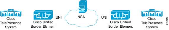
DHCP to Provision SIP Server, Domain Name, and Phone Number
NGN requires Cisco Unified Border Element to support DHCP (RFC 2131 and RFC 2132) to provision the following:
•![]() IP address for Cisco Unified Border Element's UNI interface facing NGN
IP address for Cisco Unified Border Element's UNI interface facing NGN
•![]() SIP server address using option 120
SIP server address using option 120
•![]() Option 125 vendor specific information to get:
Option 125 vendor specific information to get:
–![]() Pilot number (also called primary or contract number), there is only one pilot number in DHCPACK, and REGISTER is done only for the pilot number
Pilot number (also called primary or contract number), there is only one pilot number in DHCPACK, and REGISTER is done only for the pilot number
–![]() Additional numbers, or secondary numbers, are in DHCPACK; there is no REGISTER for additional numbers
Additional numbers, or secondary numbers, are in DHCPACK; there is no REGISTER for additional numbers
–![]() SIP domain name
SIP domain name
•![]() DHCPFORCERENEW to reset or apply a new set of SIP parameters (RFC 3203)
DHCPFORCERENEW to reset or apply a new set of SIP parameters (RFC 3203)
DHCP-SIP Call Flow
The following scenario shows the DHCP messages involved in provisioning information such as the IP address for UNI interface, and SIP parameters including the SIP server address, phone number, and domain name, along with how SIP messages use the provisioned information.
Figure 2 shows the DHCP and SIP messages involved in obtaining the SIP parameters and using them for REGISTER and INVITE.
Figure 2 DHCP-SIP Call Flow
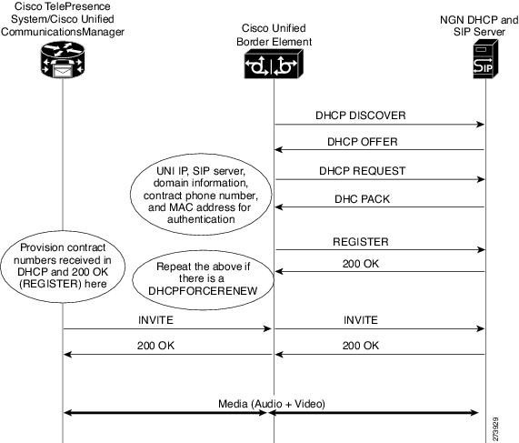
DHCP Message Details
The DHCP call flow involved in obtaining Cisco Unified Border Element provision information, including the IP address for UNI interface and SIP information such as phone number, domain, and SIP server, is shown in Figure 2.
Figure 3 DHCP Message Details
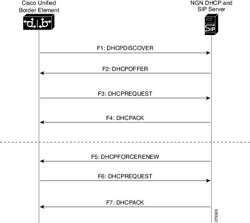
The DHCP messages involved in provisioning the SIP parameters are described in Steps 1 to 6.
1. ![]() F1: The Cisco Unified Border Element DHCP client sends a DHCPDISCOVER message to find the available NGN DHCP servers on the network and obtain a valid IPv4 address. The Cisco Unified Border Element DHCP client identity (computer name) and MAC address are included in this message.
F1: The Cisco Unified Border Element DHCP client sends a DHCPDISCOVER message to find the available NGN DHCP servers on the network and obtain a valid IPv4 address. The Cisco Unified Border Element DHCP client identity (computer name) and MAC address are included in this message.
2. ![]() F2: The Cisco Unified Border Element DHCP client receives a DHCPOFFER message from each available NGN DHCP server. The DHCPOFFER message includes the offered DHCP server's IPv4 address, the DHCP client's MAC address, and other configuration parameters.
F2: The Cisco Unified Border Element DHCP client receives a DHCPOFFER message from each available NGN DHCP server. The DHCPOFFER message includes the offered DHCP server's IPv4 address, the DHCP client's MAC address, and other configuration parameters.
3. ![]() F3: The Cisco Unified Border Element DHCP client selects an NGN DHCP server and its IPv4 address configuration from the DHCPOFFER messages it receives, and sends a DHCPREQUEST message requesting its usage. Note that this is where Cisco Unified Border Element requests SIP server information via DHCP Option 120 and vendor- identifying information via DHCP Option 125.
F3: The Cisco Unified Border Element DHCP client selects an NGN DHCP server and its IPv4 address configuration from the DHCPOFFER messages it receives, and sends a DHCPREQUEST message requesting its usage. Note that this is where Cisco Unified Border Element requests SIP server information via DHCP Option 120 and vendor- identifying information via DHCP Option 125.
4. ![]() F4: The chosen NGN DHCP server assigns its IPv4 address configuration to the Cisco Unified Border Element DHCP client by sending a DHCPACK message to it. The Cisco Unified Border Element DHCP client receives the DHCPACK message. This is where the SIP server address, phone number and domain name information are received via DHCP options 120 and 125. The Cisco Unified Border Element will use the information for registering the phone number and routing INVITE messages to the given SIP server.
F4: The chosen NGN DHCP server assigns its IPv4 address configuration to the Cisco Unified Border Element DHCP client by sending a DHCPACK message to it. The Cisco Unified Border Element DHCP client receives the DHCPACK message. This is where the SIP server address, phone number and domain name information are received via DHCP options 120 and 125. The Cisco Unified Border Element will use the information for registering the phone number and routing INVITE messages to the given SIP server.
5. ![]() F5: When NGN has a change of information or additional information (such as changing SIP server address from 1.1.1.1 to 2.2.2.2) for assigning to Cisco Unified Border Element, the DHCP server initiates DHCPFORCERENEW to the Cisco Unified Border Element. If the authentication is successful, the Cisco Unified Border Element DHCP client accepts the DHCPFORCERENEW and moves to the next stage of sending DHCPREQUEST. Otherwise DHCPFORCERENEW is ignored and the current information is retained and used.
F5: When NGN has a change of information or additional information (such as changing SIP server address from 1.1.1.1 to 2.2.2.2) for assigning to Cisco Unified Border Element, the DHCP server initiates DHCPFORCERENEW to the Cisco Unified Border Element. If the authentication is successful, the Cisco Unified Border Element DHCP client accepts the DHCPFORCERENEW and moves to the next stage of sending DHCPREQUEST. Otherwise DHCPFORCERENEW is ignored and the current information is retained and used.
6. ![]() F6 and F7: In response to DHCPFORCERENEW, similar to steps F3 and F4, the Cisco Unified Border Element requests DHCP Options 120 and 125. Upon getting the response, SIP will apply these parameters if they are different by sending an UN-REGISTER message for the previous phone number and a REGISTER message for the new number. Similarly, a new domain and SIP server address will be used. If the returned information is the same as the current set, it is ignored and hence registration and call routing remains the same.
F6 and F7: In response to DHCPFORCERENEW, similar to steps F3 and F4, the Cisco Unified Border Element requests DHCP Options 120 and 125. Upon getting the response, SIP will apply these parameters if they are different by sending an UN-REGISTER message for the previous phone number and a REGISTER message for the new number. Similarly, a new domain and SIP server address will be used. If the returned information is the same as the current set, it is ignored and hence registration and call routing remains the same.
How to Configure SIP Parameters via DHCP
To configure SIP parameters via DHCP, perform the following tasks:
•![]() Configuring the DHCP Client (Required)
Configuring the DHCP Client (Required)
•![]() Enabling the SIP Configuration (Required)
Enabling the SIP Configuration (Required)
•![]() Configuring a SIP Outbound Proxy Server (Required)
Configuring a SIP Outbound Proxy Server (Required)
•![]() Enabling Forced Update of SIP Parameters via DHCP (Required)
Enabling Forced Update of SIP Parameters via DHCP (Required)
Configuring the DHCP Client
To receive the SIP configuration parameters the Cisco Unified Border Element has to act as a DHCP client. This is because in the NGN network, a DHCP server pushes the configuration to a DHCP client. Thus the Cisco Unified Border Element must be configured as a DHCP client.
Perform this task to configure the DHCP client.
Prerequisites
You must configure the ip dhcp client commands before entering the ip address dhcp command on an interface to ensure that the DHCPDISCOVER messages that are generated contain the correct option values. The ip dhcp client commands are checked only when an IP address is acquired from DHCP. If any of the ip dhcp client commands are entered after an IP address has been acquired from DHCP, the DHCPDISCOVER messages' correct options will not be present or take effect until the next time the router acquires an IP address from DHCP. This means that the new configuration will only take effect after either the ip address dhcp command or the release dhcp and renew dhcp EXEC commands have been configured.
SUMMARY STEPS
1. ![]() enable
enable
2. ![]() configure terminal
configure terminal
3. ![]() interface type number
interface type number
4. ![]() ip address dhcp
ip address dhcp
5. ![]() ip dhcp client request sip-server-address
ip dhcp client request sip-server-address
6. ![]() ip dhcp client request vendor-identifying-specific
ip dhcp client request vendor-identifying-specific
7. ![]() exit
exit
Enabling the SIP Configuration
Enabling the SIP configuration allows the Cisco Unified Border Element to use the SIP parameters received via DHCP for user registration and call routing.
Perform this task to enable the SIP configuration.
Prerequisites
The dhcp interface command has to be entered to declare the interface before the registrar and credential commands are entered.
SUMMARY STEPS
1. ![]() enable
enable
2. ![]() configure terminal
configure terminal
3. ![]() interface type number
interface type number
4. ![]() sip-ua
sip-ua
5. ![]() dhcp interface type number
dhcp interface type number
6. ![]() registrar dhcp expires seconds random-contact refresh-ratio seconds
registrar dhcp expires seconds random-contact refresh-ratio seconds
7. ![]() credentials dhcp password [0 | 7] password realm domain-name
credentials dhcp password [0 | 7] password realm domain-name
8. ![]() exit
exit
Troubleshooting Tips
To display information on DHCP and SIP interaction when SIP parameters are provisioned by DHCP, use the debug ccsip dhcp command in privileged EXEC mode.
Configuring a SIP Outbound Proxy Server
An outbound-proxy configuration sets the Layer 3 address (IP address) for any outbound REGISTER and INVITE SIP messages. The SIP server can be configured as an outbound proxy server in voice service SIP configuration mode or dial peer configuration mode. When enabled in voice service SIP configuration mode, all the REGISTER and INVITE messages are forwarded to the configured outbound proxy server. When enabled in dial-peer configuration mode, only the messages hitting the defined dial-peer will be forwarded to the configured outbound proxy server.
The configuration tasks in each mode are presented in the following sections:
•![]() Configuring a SIP Outbound Proxy Server in Voice Service VoIP Configuration Mode
Configuring a SIP Outbound Proxy Server in Voice Service VoIP Configuration Mode
•![]() Configuring a SIP Outbound Proxy Server and Session Target in Dial Peer Configuration Mode
Configuring a SIP Outbound Proxy Server and Session Target in Dial Peer Configuration Mode
Perform either of these tasks to configure the SIP server as a SIP outbound proxy server.
Configuring a SIP Outbound Proxy Server in Voice Service VoIP Configuration Mode
Perform this task to configure the SIP server as a SIP outbound proxy server in voice service SIP configuration mode.
SUMMARY STEPS
1. ![]() enable
enable
2. ![]() configure terminal
configure terminal
3. ![]() voice service voip
voice service voip
4. ![]() sip
sip
5. ![]() outbound-proxy dhcp
outbound-proxy dhcp
6. ![]() exit
exit
Configuring a SIP Outbound Proxy Server and Session Target in Dial Peer Configuration Mode
Perform this task to configure the SIP server as a SIP outbound proxy server in dial peer configuration mode.
Restrictions
SIP must be configured on the dial pier before DHCP is configured. Therefore the session protocol sipv2 command must be executed before the session target dhcp command. DHCP is supported only with SIP configured on the dial peer.
SUMMARY STEPS
1. ![]() enable
enable
2. ![]() configure terminal
configure terminal
3. ![]() dial-peer voice number voip
dial-peer voice number voip
4. ![]() session protocol sipv2
session protocol sipv2
5. ![]() voice-class sip outbound-proxy dhcp
voice-class sip outbound-proxy dhcp
6. ![]() session target dhcp
session target dhcp
7. ![]() exit
exit
Enabling Forced Update of SIP Parameters via DHCP
In the event of changes to the SIP parameter values, a DHCP message called DHCPFORCERENEW can reset or apply a new set of values. The NGN can add or change phone number, SIP server address and domain name by sending DHCPFORCERENEW. When the SIP server receives the SIP parameter values, it compares the existing values to see if they are the same or if they have changed. If they are the same, the existing SIP parameters continue to be used. If they are different, the current phone number is unregistered and the new one registered, and the new SIP server address and domain name are used.
Prerequisites
To enable this feature, you must have Cisco IOS Release 12.4(22)YB or a later release installed and running on your Cisco gateway. For detailed information on platform availability and subsequent releases, see the "Feature Information for SIP-to-SIP Connections on a Cisco Unified Border Element" section.
The DHCP provisioning of SIP parameters must be enabled.
This feature provides the ability for a DHCP server to add or change SIP signaling configuration and routing information related parameters via DHCP FORCERENEW. The DHCP client in IOS is required to restart REGISTRATION and use updated parameters for subsequent SIP dialogs
•![]() Commands Required to turn on the feature.
Commands Required to turn on the feature.
–![]() dhcp interface <intf>
dhcp interface <intf>
–![]() registrar dhcp
registrar dhcp
–![]() credentials dhcp password <password> realm <realm>
credentials dhcp password <password> realm <realm>
Restrictions
•![]() DHCP Option 120 is the standard DHCP option (RFC3361) to get an SIP server address, and this can be used by any vendor DHCP server. Only one address is supported, which is in the IPv4 address format. Multiple IPv4 address entries are not supported. Additionally, a DNS name and any port number given behind the IPv4 address is not supported.
DHCP Option 120 is the standard DHCP option (RFC3361) to get an SIP server address, and this can be used by any vendor DHCP server. Only one address is supported, which is in the IPv4 address format. Multiple IPv4 address entries are not supported. Additionally, a DNS name and any port number given behind the IPv4 address is not supported.
•![]() DHCP Option 125 (RFC3925) provides vendor specific information. Its interpretation is tied up with the enterprise id. The primary and secondary phone numbers and domain are obtained using option 125 which is vendor specific. As long as other customers use the same format as in the NGN DHCP specification, they can leverage this feature.
DHCP Option 125 (RFC3925) provides vendor specific information. Its interpretation is tied up with the enterprise id. The primary and secondary phone numbers and domain are obtained using option 125 which is vendor specific. As long as other customers use the same format as in the NGN DHCP specification, they can leverage this feature.
•![]() The presence of the primary number in sub-option 202 of DHCP option 125 is mandatory. There can only be one instance of the primary number and not multiple instances.
The presence of the primary number in sub-option 202 of DHCP option 125 is mandatory. There can only be one instance of the primary number and not multiple instances.
•![]() Multiple secondary numbers in sub-option 203 of DHCP option 125 are supported. Up to five numbers are accepted and the rest are ignored. Also, they have to follow behind the primary number in the DHCP packet data.
Multiple secondary numbers in sub-option 203 of DHCP option 125 are supported. Up to five numbers are accepted and the rest are ignored. Also, they have to follow behind the primary number in the DHCP packet data.
•![]() Authentication is not supported for REGISTER and INVITE messages sent from a CUBE that uses DHCP provisioning.
Authentication is not supported for REGISTER and INVITE messages sent from a CUBE that uses DHCP provisioning.
•![]() The DHCP provisioning of SIP Parameters is only supported over one DHCP interface.
The DHCP provisioning of SIP Parameters is only supported over one DHCP interface.
•![]() The DHCP option is only available to be configured for the primary registrar. It will not be available for a secondary registrar.
The DHCP option is only available to be configured for the primary registrar. It will not be available for a secondary registrar.
SUMMARY STEPS
1. ![]() enable
enable
2. ![]() configure terminal
configure terminal
3. ![]() ip dhcp-client forcerenew
ip dhcp-client forcerenew
4. ![]() exit
exit
Configuration Examples for Configurable SIP Parameters via DHCP
This section contains the following configuration examples:
•![]() Configuring the DHCP Client: Example
Configuring the DHCP Client: Example
•![]() Enabling the SIP Configuration: Example
Enabling the SIP Configuration: Example
•![]() Configuring a SIP Outbound Proxy Server in Voice Service VoIP Configuration Mode: Example
Configuring a SIP Outbound Proxy Server in Voice Service VoIP Configuration Mode: Example
•![]() Configuring a SIP Outbound Proxy Server in Dial Peer Configuration Mode: Example
Configuring a SIP Outbound Proxy Server in Dial Peer Configuration Mode: Example
•![]() Enabling Forced Update of SIP Parameters via DHCP: Example
Enabling Forced Update of SIP Parameters via DHCP: Example
Configuring the DHCP Client: Example
The following is an example of how to enable the DHCP client:
Router> enable
Router# configure terminal
Router(config)# interface gigabitethernet 1/1
Router(config-if)# ip dhcp client request sip-server-address
Router(config-if)# ip dhcp client request vendor-identifying-specific
Router(config-if)# ip address dhcp
Router(config-if)# exit
Enabling the SIP Configuration: Example
The following is an example of how to enable the SIP configuration:
Router> enable
Router# configure terminal
Router(config)# interface gigabitethernet 1/0
Router(config-if)# sip-ua
Router(sip-ua)# dhcp interface gigabitethernet 1/0
Router(sip-ua)# registrar dhcp expires 90 random-contact refresh-ratio 90
Router(sip-ua)# credentials dhcp password cisco realm cisco.com
Router(sip-ua)# exit
Configuring a SIP Outbound Proxy Server in Voice Service VoIP Configuration Mode: Example
The following is an example of how to configure a SIP outbound proxy in voice service SIP
configuration mode:
Router> enable
Router# configure terminal
Router(config)# voice service voip
Router(config-voi-srv)# sip
Router(conf-serv-sip)# outbound-proxy dhcp
Router(config-serv-if)# exit
Configuring a SIP Outbound Proxy Server in Dial Peer Configuration Mode: Example
The following is an example of how to configure a SIP outbound proxy in dial peer
configuration mode:
Router> enable
Router# configure terminal
Router(config)# dial-peer voice 11 voip
Router(config-dial-peer)# session protocol sipv2
Router(config-dial-peer)# voice-class sip outbound-proxy dhcp
Router(config-dial-peer)# session target dhcp
Router(config-dial-peer)# exit
Enabling Forced Update of SIP Parameters via DHCP: Example
The following is an example of how to enable forced update of SIP parameters via DHCP:
Router> enable
Router# configure terminal
Router(config)# ip dhcp-client forcerenew
Router(config)# exit
Configuring SIP Listening Port
To manually change the SIP listen port for UDP/TCP/TLS calls, perform the steps in this section:
Prerequisites
•![]() To enable this feature, you must have Cisco IOS Release XXX or a later release installed and running on your Cisco gateway. For detailed information on platform availability and subsequent releases, see the "Feature Information for SIP-to-SIP Connections on a Cisco Unified Border Element" section.
To enable this feature, you must have Cisco IOS Release XXX or a later release installed and running on your Cisco gateway. For detailed information on platform availability and subsequent releases, see the "Feature Information for SIP-to-SIP Connections on a Cisco Unified Border Element" section.
•![]() Configure the shutdown command in sip configuration mode first. This ensures that there are no active calls when the SIP listen port is changed. If SIP service is not shutdown, the listen-port command flashes an error message saying "shutdown SIP service before changing SIP listen port".
Configure the shutdown command in sip configuration mode first. This ensures that there are no active calls when the SIP listen port is changed. If SIP service is not shutdown, the listen-port command flashes an error message saying "shutdown SIP service before changing SIP listen port".
•![]() This feature is applicable for both incoming and outgoing call SIP.
This feature is applicable for both incoming and outgoing call SIP.
•![]() The IP-to-IP gateway port number defined in global configuration will be used for both IN leg and OUT leg.
The IP-to-IP gateway port number defined in global configuration will be used for both IN leg and OUT leg.
Restrictions
•![]() Configuring SIP listening port on a dial-peer basis is not supported.
Configuring SIP listening port on a dial-peer basis is not supported.
•![]() Configuring the same listening port for both UDP/TCP and TLS is not supported.
Configuring the same listening port for both UDP/TCP and TLS is not supported.
•![]() Configuring SIP listen port to a port that is already in use is not supported, and results in an error message.
Configuring SIP listen port to a port that is already in use is not supported, and results in an error message.
•![]() Changing the SIP listening port when Transport Process (TCP/UDP/TLS) services are shutdown, will not close or reopen the port. The only result is that the new port number is updated. The new port is bound when transport services (TCP/UDP/TLS) is enabled.
Changing the SIP listening port when Transport Process (TCP/UDP/TLS) services are shutdown, will not close or reopen the port. The only result is that the new port number is updated. The new port is bound when transport services (TCP/UDP/TLS) is enabled.
•![]() Both secure and non-secure keywords are supported on Crypto images
Both secure and non-secure keywords are supported on Crypto images
•![]() The non-secure keyword is supported on non-Crypto images.
The non-secure keyword is supported on non-Crypto images.
SUMMARY STEPS
1. ![]() enable
enable
2. ![]() configure terminal
configure terminal
3. ![]() voice service voip
voice service voip
4. ![]() sip
sip
5. ![]() listen-port {non-secure | secure} port-number
listen-port {non-secure | secure} port-number
6. ![]() exit
exit
7. ![]() end
end
Configuring Bandwidth Parameters for SIP Calls
This feature provides a CLI command that is configured under each dialpeer that is triggered when an outbound SIP call is made using this dialpeer. The configured value for the Bandwidth command overwrite the default bandwidth that is determined by the codec selected. This command is helpful to allow the bandwidth to be signalled independent of the specific codec used
To manually change the SIP listen port for UDP/TCP/TLS calls, perform the steps in this section:
Prerequisites
•![]() To enable this feature, you must have Cisco IOS Release XXX or a later release installed and running on your Cisco gateway. For detailed information on platform availability and subsequent releases, see the "Feature Information for SIP-to-SIP Connections on a Cisco Unified Border Element" section.
To enable this feature, you must have Cisco IOS Release XXX or a later release installed and running on your Cisco gateway. For detailed information on platform availability and subsequent releases, see the "Feature Information for SIP-to-SIP Connections on a Cisco Unified Border Element" section.
•![]() Configure the shutdown command in sip configuration mode first. This ensures that there are no active calls when the SIP listen port is changed. If SIP service is not shutdown, the listen-port command flashes an error message saying "shutdown SIP service before changing SIP listen port".
Configure the shutdown command in sip configuration mode first. This ensures that there are no active calls when the SIP listen port is changed. If SIP service is not shutdown, the listen-port command flashes an error message saying "shutdown SIP service before changing SIP listen port".
•![]() This feature is applicable for both incoming and outgoing call SIP.
This feature is applicable for both incoming and outgoing call SIP.
•![]() The Cisco Unified BE port number defined in global configuration will be used for both IN leg and OUT leg.
The Cisco Unified BE port number defined in global configuration will be used for both IN leg and OUT leg.
Restrictions
•![]() Configuring SIP listening port on a dial-peer basis is not supported.
Configuring SIP listening port on a dial-peer basis is not supported.
Configuring Support for Session Refresh with Reinvites
Configuring support for session refresh with reinvites expands the ability of the Cisco Unified BE to receive a REINVITE message that contains either a session refresh parameter or a change in media via a new SDP and ensure the session does not time out. The midcall-signaling command distinguishes between the way a Cisco Unified Communications Express and Cisco Unified Border Element releases signaling messages. Most SIP-to-SIP video and SIP-to-SIP ReInvite-based supplementary services features require the Configuring Session Refresh with Reinvites feature to be configured.
Cisco IOS Release 12.4(15)XZ and Earlier Releases
Session refresh support via OPTIONS method. For configuration information, see the "Enabling In-Dialog OPTIONS to Monitor Active SIP Sessions" section.
Cisco IOS Release 12.4(15)XZ and Later Releases
Cisco Unified BE transparently passes other session refresh messages and parameters so that UAs and proxies can establish keepalives on a call.
Prerequisites
•![]() To enable this feature, you must have Cisco IOS Release XXX or a later release installed and running on your Cisco gateway. For detailed information on platform availability and subsequent releases, see the "Feature Information for SIP-to-SIP Connections on a Cisco Unified Border Element" section.
To enable this feature, you must have Cisco IOS Release XXX or a later release installed and running on your Cisco gateway. For detailed information on platform availability and subsequent releases, see the "Feature Information for SIP-to-SIP Connections on a Cisco Unified Border Element" section.
•![]() The allow-connections sip to sip command must be configured before you configure the Session refresh with Reinvites feature. For more information and configuration steps see the "Configuring SIP-to-SIP Connections on a Cisco Unified Border Element" section.
The allow-connections sip to sip command must be configured before you configure the Session refresh with Reinvites feature. For more information and configuration steps see the "Configuring SIP-to-SIP Connections on a Cisco Unified Border Element" section.
Restrictions
•![]() SIP-to-SIP video calls and SIP-to-SIP ReInvite-based supplementary services fail if the midcall-signaling command is not configured.
SIP-to-SIP video calls and SIP-to-SIP ReInvite-based supplementary services fail if the midcall-signaling command is not configured.
Note ![]() The following features function if the midcall-signaling command is not configured: session refresh, fax, and refer-based supplementary services.
The following features function if the midcall-signaling command is not configured: session refresh, fax, and refer-based supplementary services.
•![]() Configuring Session Refresh with Reinvites is for SIP-to-SIP calls only. All other calls (H323-to-SIP, and H323-to-H323) do not require the midcall-signaling command be configured
Configuring Session Refresh with Reinvites is for SIP-to-SIP calls only. All other calls (H323-to-SIP, and H323-to-H323) do not require the midcall-signaling command be configured
•![]() Configuring the Session Refresh with Reinvites feature on a dial-peer basis is not supported.
Configuring the Session Refresh with Reinvites feature on a dial-peer basis is not supported.
SUMMARY STEPS
1. ![]() enable
enable
2. ![]() configure terminal
configure terminal
3. ![]() voice service voip
voice service voip
4. ![]() sip
sip
5. ![]() midcall-signaling passthru
midcall-signaling passthru
6. ![]() exit
exit
7. ![]() end
end
Sending a SIP Registration Message from a Cisco Unified Border Element
The credentials command allows you to send a SIP registration message from a Cisco Unified Border Element in the UP state. Registration can include numbers, number ranges (such as E.164-numbers), or text information.
Before Cisco IOS Release12.4(24)T, a POTS dial peer was required to register numbers from a Cisco Unified Border Element in the UP state. The credentials command is modified in Release 12.4(24s)T to allow for registration of the E.164-numbers, if there is no POTS dial peer.
Prerequisites
•![]() To enable this feature, you must have Cisco IOS Release XXX or a later release installed and running on your Cisco gateway. For detailed information on platform availability and subsequent releases, see the "Feature Information for SIP-to-SIP Connections on a Cisco Unified Border Element" section.
To enable this feature, you must have Cisco IOS Release XXX or a later release installed and running on your Cisco gateway. For detailed information on platform availability and subsequent releases, see the "Feature Information for SIP-to-SIP Connections on a Cisco Unified Border Element" section.
•![]() Configure a registrar in sip user-agent configuration mode.
Configure a registrar in sip user-agent configuration mode.
SUMMARY STEPS
1. ![]() enable
enable
2. ![]() configure terminal
configure terminal
3. ![]() sip-uaF
sip-uaF
4. ![]() credentials username username password password realm domain-name
credentials username username password password realm domain-name
5. ![]() exit
exit
6. ![]() end
end
Configuring Adjustable Timers for Registration Refresh and Retries
Configuring Adjustable Timers for Registration Refresh and Retries provides the ability for IOS software to refresh the REGISTER at a configurable fraction of the expiry timer specified in the 200 OK response of the REGISTER request. The feature also provides the ability to retransmit REGISTER upon receiving failure responses as per the min-expires header value in a "423 interval too brief" response, or retry-after if header value if present or terminal re-registration interval if retry-after header value is absent in 4xx/5xx/6xx responses. Additionally, the ability to retransmit REGISTER per Timer E up to 32 seconds, and at a command line interface controlled random interval thereafter.
This feature addresses the UNI SIP registration specification requirements on Cisco Unified Border Element to interwork CTS over NGN and includes the following are SIP registration enhancements:
423 Interval Too Brief Response Handling
Cisco Unified Border Element retransmits the REGISTER request with the received Min-Expires value in the 423 response. The retransmit interval is the same as the configured REGISTER refresh ratio.
If the registration response from the REGISTRAR server is a "423 Interval Too Brief", the configured registration expires time-value sent in the REGISTER message does not apply. The 423 response contains the acceptable expires time value in the Min-Expires header. The newly received time value is then used in the Expires header when the next registration refresh request is sent.
4xx/5xx/6xx Error Response Handling (Except 423)
If the registration response from the REGISTRAR server is a 4xx/5xx/6xx (except 423) message, an error has occurred. The retransmit interval uses the value in the Retry-After header if present in the 4xx/5xx/6xx response. The only supported Retry-After header format is `Retry-After:1800'. If "Retry-After" header is not present in the error response, the configured refresh ratio and "Expires" time value will be used to calculate the interval between the sending of the next REGISTER message or it will be the default retransmit interval.
Configurable REGISTER Refresh Ratio
The Cisco Unified Border Element sends REGISTER refresh at 40% to 50% of the expiry time as specified in 200 OK response of REGISTER request. Use the refresh-ratio keyword to configure the REGISTER refresh ratio. If the refresh-ratio option is not configured, the default REGISTER refresh ratio is 80% of the expiry timer. The minimum refresh interval is one minute.
No REGISTER Response Handling
The Cisco Unified Border Element handles no response to REGISTER by retransmitting at intervals Timer E for up to a maximum of 32 seconds. If no REGISTER response is received from the REGISTRAR server, the REGISTER message will be retransmitted. By configuring the retry register command to 10, the Cisco Unified Border Element retransmits the REGISTER (starting at 500 ms) and continues to retransmit at double the rate, to a maximum of 4 seconds. The default REGISTER retransmit count is six retries, after which the Cisco Unified Border Element retries REGISTER request at a random interval (5 to 10 minutes).
There is a two minute interval after which the REGISTER retransmits begin again. The retry register exhausted-random-interval command allows the user to set a desired interval after the number of REGISTER retransmits have been exhausted. This also allows the user to set a range in which a number (in minutes) is randomly generated and used as the interval between retransmission exhaustion.
The default REGISTER refresh ratio is eighty percent (80%) of the expiry time. The default REGISTER error retransmit interval is 5% of the configured expiry time or two minutes, whichever is greater.
Random String in REGISTER Contact
Cisco Unified Border Element uses a random string in the Contact header of the REGISTER message. The random string consists of alphanumeric characters. A different random string is generated and used for each number registered.
Prerequisites
To enable this feature, you must have Cisco IOS Release XXX or a later release installed and running on your Cisco gateway. For detailed information on platform availability and subsequent releases, see the "Feature Information for SIP-to-SIP Connections on a Cisco Unified Border Element" section.
To configure Adjustable Timers for Registration Refresh and Retries, perform the steps in this section:
SUMMARY STEPS
1. ![]() enable
enable
2. ![]() configure terminal
configure terminal
3. ![]() sip-ua
sip-ua
4. ![]() registrar expires seconds refresh-ratio seconds random-contact
registrar expires seconds refresh-ratio seconds random-contact
5. ![]() retry register retries exhausted-random-interval minimum minutes maximum minutes
retry register retries exhausted-random-interval minimum minutes maximum minutes
6. ![]() exit
exit
Cisco Unified Border Element Support for SRTP-RTP Internetworking
The Cisco Unified Border Element Support for SRTP-RTP Internetworking feature allows secure enterprise-to-enterprise calls. The feature also provides operational enhancements for Session Initiation Protocol (SIP) trunks from Cisco Unified Call Manager and Cisco Unified Call Manager Express. Support for Secure Real-Time Transport Protocol (SRTP)-RTP internetworking between one or multiple Cisco Unified Border Elements is enabled for SIP-SIP audio calls.
Prerequisites for Cisco Unified Border Element Support for SRTP-RTP Internetworking
•![]() To enable this feature, you must have Cisco IOS Release 12.4(22(YB) or a later release installed and running on your Cisco gateway. For detailed information on platform availability and subsequent releases, see the "Feature Information for SIP-to-SIP Connections on a Cisco Unified Border Element" section.
To enable this feature, you must have Cisco IOS Release 12.4(22(YB) or a later release installed and running on your Cisco gateway. For detailed information on platform availability and subsequent releases, see the "Feature Information for SIP-to-SIP Connections on a Cisco Unified Border Element" section.
•![]() The Cisco Unified Border Element Support for SRTP-RTP Internetworking feature is supported in Cisco Unified CallManager 7.0 and later releases.
The Cisco Unified Border Element Support for SRTP-RTP Internetworking feature is supported in Cisco Unified CallManager 7.0 and later releases.
Restrictions for Cisco Unified Border Element Support for SRTP-RTP Internetworking
The following features are not supported by the Cisco Unified Border Element Support for SRTP-RTP Internetworking feature:
•![]() Voice-class codec
Voice-class codec
•![]() Call admission control (CAC) support
Call admission control (CAC) support
•![]() Rotary SIP-SIP
Rotary SIP-SIP
•![]() T.38 Fax
T.38 Fax
•![]() Early offer to delayed offer calls
Early offer to delayed offer calls
•![]() Delayed offer to early offer calls
Delayed offer to early offer calls
Information About Cisco Unified Border Element Support for SRTP-RTP Internetworking
To configure support for SRTP-RTP internetworking, you should understand the following concepts:
•![]() Cisco Unified Border Element Support for SRTP-RTP Internetworking
Cisco Unified Border Element Support for SRTP-RTP Internetworking
•![]() TLS on the Cisco Unified Border Element
TLS on the Cisco Unified Border Element
Cisco Unified Border Element Support for SRTP-RTP Internetworking
The Cisco Unified Border Element Support for SRTP-RTP Internetworking feature connects SRTP Cisco Unified CallManager domains with the following:
•![]() RTP Cisco Unified CallManager domains. Domains that do not support SRTP, or have not been configured for SRTP, as shown in Figure 4.
RTP Cisco Unified CallManager domains. Domains that do not support SRTP, or have not been configured for SRTP, as shown in Figure 4.
•![]() RTP Cisco applications or servers. For example, Cisco Unified MeetingPlace, Cisco WebEx, or Cisco Unity, which do not support SRTP, or have not been configured for SRTP, or are resident in a secure data center, as shown in Figure 4.
RTP Cisco applications or servers. For example, Cisco Unified MeetingPlace, Cisco WebEx, or Cisco Unity, which do not support SRTP, or have not been configured for SRTP, or are resident in a secure data center, as shown in Figure 4.
•![]() RTP to third-party equipment. For example, IP trunks to PBXs or virtual machines, which do not support SRTP.
RTP to third-party equipment. For example, IP trunks to PBXs or virtual machines, which do not support SRTP.
Figure 4 SRTP Domain Connections
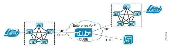
The Cisco Unified Border Element Support for SRTP-RTP Internetworking feature connects SRTP enterprise domains to RTP SIP provider (SP) SIP trunks. SRTP-RTP internetworking connects RTP enterprise networks with SRTP over an external network between businesses. This provides flexible secure business-to-business communications without the need for static IPsec tunnels or the need to deploy SRTP within the enterprise, as shown in Figure 5. SRTP-RTP internetworking also connects SRTP enterprise networks with static IPsec over external networks, as shown in Figure 6.
Figure 5
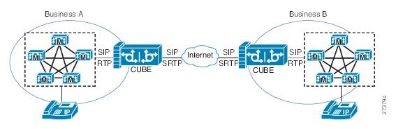
Secure Business-to-Business Communications
Figure 6
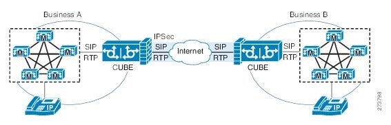
SRTP Enterprise Network Connections
SRTP-RTP internetworking on the Cisco Unified Border Element in a network topology uses single pair key generation. Existing audio and dual-tone multifrequency (DTMF) transcoding is used to support voice calls. SRTP-RTP internetworking support is provided in both flow-through and high-density mode. SRTP-SRTP pass-through is not impacted.
SRTP is configured on one dial peer and RTP is configured on the other dial peer using the srtp and srtp fallback commands. The dial-peer configuration takes precedence over the global configuration on the Cisco Unified Border Element.
Fallback handling occurs if one of the call endpoints does not support SRTP. The call can fall back to RTP-RTP, or the call can fail, depending on the configuration. Fallback takes place only if the srtp fallback command is configured on the respective dial peer. RTP-RTP fall back occurs when no transcoding resources are available for SRTP-RTP internetworking.
TLS on the Cisco Unified Border Element
The Cisco Unified Border Element Support for SRTP-RTP Internetworking feature allows Transport Layer Security (TLS) to be enabled or disabled between the SCCP server and SCCP client. By default TLS is enabled, which provides added protection at transport level and ensures that SRTP keys are not easily accessible. Once TLS is disabled, the SRTP keys are not protected.
SRTP-RTP internetworking is available with normal and universal transcoders. The transcoder on the Cisco Unified Border Element is invoked using SCCP messaging between the SCCP server and the SCCP client. The SCCP messages carry the SRTP keys to the digital signal processor (DSP) farm at the SCCP client. The transcoder can be within the same router or can be located in a separate router. TLS should be disabled only when the transcoder is located in the same router. To disable TLS, configure the no form of the tls command in dsp farm profile configuration mode. Disabling TLS improves CPU performance.
How to Configure Cisco Unified Border Element Support for SRTP-RTP Internetworking
This section contains the following task:
•![]() Configuring Cisco Unified Border Element Support for SRTP-RTP Internetworking (required)
Configuring Cisco Unified Border Element Support for SRTP-RTP Internetworking (required)
Configuring Cisco Unified Border Element Support for SRTP-RTP Internetworking
Configuring the Cisco Unified Border Element Support for SRTP-RTP Internetworking feature consists of the following tasks:
•![]() Configuring the Certificate Authority (required)
Configuring the Certificate Authority (required)
•![]() Configuring a Trustpoint for the Secure Universal Transcoder (required)
Configuring a Trustpoint for the Secure Universal Transcoder (required)
•![]() Configuring DSP Farm Services (required)
Configuring DSP Farm Services (required)
•![]() Associating SCCP to the Secure DSP Farm Profile (required)
Associating SCCP to the Secure DSP Farm Profile (required)
•![]() Registering the Secure Universal Transcoder to the Cisco Unified Border Element (required)
Registering the Secure Universal Transcoder to the Cisco Unified Border Element (required)
•![]() Configuring SRTP-RTP Internetworking Support (required)
Configuring SRTP-RTP Internetworking Support (required)
Configuring the Certificate Authority
Perform the steps described in this section to configure the certificate authority.
SUMMARY STEPS
1. ![]() enable
enable
2. ![]() configure terminal
configure terminal
3. ![]() ip http server
ip http server
4. ![]() crypto pki server cs-label
crypto pki server cs-label
5. ![]() database level complete
database level complete
6. ![]() grant auto
grant auto
7. ![]() no shutdown
no shutdown
8. ![]() exit
exit
Configuring a Trustpoint for the Secure Universal Transcoder
Perform the steps in this section to configure, authenticate, and enroll the trustpoint for the secure universal transcoder.
Prerequisites
Before you configure the trustpoint for the secure universal transcoder, you should configure the certificate authority, as described in the "Configuring the Certificate Authority" section.
SUMMARY STEPS
1. ![]() enable
enable
2. ![]() configure terminal
configure terminal
3. ![]() crypto pki trustpoint name
crypto pki trustpoint name
4. ![]() enrollment url url
enrollment url url
5. ![]() serial-number
serial-number
6. ![]() revocation-check method
revocation-check method
7. ![]() rsakeypair key-label
rsakeypair key-label
8. ![]() end
end
9. ![]() crypto pki authenticate name
crypto pki authenticate name
10. ![]() crypto pki enroll name
crypto pki enroll name
11. ![]() exit
exit
Configuring DSP Farm Services
Perform the steps in this section to configure DSP farm services.
Prerequisites
Before you configure DSP farm services, you should configure the trustpoint for the secure universal transcoder, as described in the "Configuring a Trustpoint for the Secure Universal Transcoder" section.
SUMMARY STEPS
1. ![]() enable
enable
2. ![]() configure terminal
configure terminal
3. ![]() voice-card slot
voice-card slot
4. ![]() dspfarm
dspfarm
5. ![]() dsp services dspfarm
dsp services dspfarm
6. ![]() Repeat Steps 3,4, and 5 to configure a second voice card.
Repeat Steps 3,4, and 5 to configure a second voice card.
7. ![]() exit
exit
Associating SCCP to the Secure DSP Farm Profile
Perform the steps in this section to associate SCCP to the secure DSP farm profile.
Prerequisites
Before you associate SCCP to the secure DSP farm profile, you should configure DSP farm services, as described in the "Configuring DSP Farm Services" section.
SUMMARY STEPS
1. ![]() enable
enable
2. ![]() configure terminal
configure terminal
3. ![]() sccp local interface-type interface-number
sccp local interface-type interface-number
4. ![]() sccp ccm ip-address identifier identifier-number version version-number
sccp ccm ip-address identifier identifier-number version version-number
5. ![]() sccp
sccp
6. ![]() associate ccm identifier-number priority priority-number
associate ccm identifier-number priority priority-number
7. ![]() associate profile profile-identifier register device-name
associate profile profile-identifier register device-name
8. ![]() dspfarm profile profile-identifier transcode universal security
dspfarm profile profile-identifier transcode universal security
9. ![]() trustpoint trustpoint-label
trustpoint trustpoint-label
10. ![]() codec codec-type
codec codec-type
11. ![]() Repeat Step 10 to configure required codecs.
Repeat Step 10 to configure required codecs.
12. ![]() maximum sessions number
maximum sessions number
13. ![]() associate application sccp
associate application sccp
14. ![]() no shutdown
no shutdown
15. ![]() exit
exit
Registering the Secure Universal Transcoder to the Cisco Unified Border Element
Perform the steps in this section to register the secure universal transcoder to the Cisco Unified Border Element. The Cisco Unified Border Element Support for SRTP-RTP Internetworking feature supports both secure transcoders and secure universal transcoders.
Prerequisites
Before you register the secure universal transcoder to the Cisco Unified Border Element, you should associated SCCP to the secure DSP farm profile, as described in the "Associating SCCP to the Secure DSP Farm Profile" section.
SUMMARY STEPS
1. ![]() enable
enable
2. ![]() configure terminal
configure terminal
3. ![]() telephony-service
telephony-service
4. ![]() sdspfarm transcode sessions number
sdspfarm transcode sessions number
5. ![]() sdspfarm tag number device-name
sdspfarm tag number device-name
6. ![]() em logout time1 time2 time3
em logout time1 time2 time3
7. ![]() max-ephones max-phones
max-ephones max-phones
8. ![]() max-dn max-directory-numbers
max-dn max-directory-numbers
9. ![]() ip source-address ip-address
ip source-address ip-address
10. ![]() secure-signaling trustpoint label
secure-signaling trustpoint label
11. ![]() tftp-server-credentials trustpoint label
tftp-server-credentials trustpoint label
12. ![]() create cnf-files
create cnf-files
13. ![]() no sccp
no sccp
14. ![]() sccp
sccp
15. ![]() end
end
Configuring SRTP-RTP Internetworking Support
Perform the steps in this section to enable SRTP-RTP internetworking support between one or multiple Cisco Unified Border Elements for SIP-SIP audio calls. In this task, RTP is configured on the incoming call leg and SRTP is configured on the outgoing call leg.
Prerequisites
Before you configure the Cisco Unified Border Element Support for SRTP-RTP Internetworking feature, you should register the secure universal transcoder to the Cisco Unified Border Element, as described in the "Registering the Secure Universal Transcoder to the Cisco Unified Border Element" section.
Restrictions
The Cisco Unified Border Element Support for SRTP-RTP Internetworking feature is available only on platforms that support transcoding on the Cisco Unified Border Element. The feature is also available only on secure Cisco IOS images on the Cisco Unified Border Element.
SUMMARY STEPS
1. ![]() enable
enable
2. ![]() configure terminal
configure terminal
3. ![]() dial-peer voice tag voip
dial-peer voice tag voip
4. ![]() destination-pattern string
destination-pattern string
5. ![]() session protocol sipv2
session protocol sipv2
6. ![]() session target ipv4:destination-address
session target ipv4:destination-address
7. ![]() incoming called-number string
incoming called-number string
8. ![]() codec codec
codec codec
9. ![]() end
end
10. ![]() dial-peer voice tag voip
dial-peer voice tag voip
11. ![]() Repeat Steps 4, 5, 6, and 7 to configure a second dial peer.
Repeat Steps 4, 5, 6, and 7 to configure a second dial peer.
12. ![]() srtp
srtp
13. ![]() exit
exit
Troubleshooting Tips
The following commands can help troubleshoot Cisco Unified Border Element support for SRTP-RTP internetworking:
•![]() show crypto pki certificates
show crypto pki certificates
•![]() show sccp
show sccp
•![]() show sdspfarm
show sdspfarm
Configuring Assisted Real-time Transport Control Protocol (RTCP) Report Generation
The assisted Real-time Transport Control Protocol (RTCP) feature adds the ability for Cisco Unified Border Element (Cisco UBE) to generate standard RTCP keepalive reports on behalf of endpoints. RTCP reports determine the liveliness of a media session during prolonged periods of silence, such as call hold or mute. Therefore, it is important for the Cisco UBE to generate RTCP reports irrespective of whether the endpoints send or receive media.
Cisco UBE generates RTCP report only when inbound and outbound call legs are SIP, or SIP to H.323, or H.323 to SIP.
Restrictions
•![]() RTCP report generation over IPv6 is not supported.
RTCP report generation over IPv6 is not supported.
•![]() RTCP report generation is not supported for Secure Real-time Transport Protocol (SRTP) or SRT Control Protocol (SRTCP) pass-through as Cisco UBE is not aware of the media encryption or decryption keys.
RTCP report generation is not supported for Secure Real-time Transport Protocol (SRTP) or SRT Control Protocol (SRTCP) pass-through as Cisco UBE is not aware of the media encryption or decryption keys.
•![]() RTCP report generation is not supported for loopback calls, T.38 fax, and modem relay calls.
RTCP report generation is not supported for loopback calls, T.38 fax, and modem relay calls.
•![]() RTCP or SRTCP report generation is not supported when Cisco UBE inserts a Digital Signal Processor (DSP) for RTP-SRTP interworking on RTP and SRTP call legs.
RTCP or SRTCP report generation is not supported when Cisco UBE inserts a Digital Signal Processor (DSP) for RTP-SRTP interworking on RTP and SRTP call legs.
•![]() RTCP report generation is not supported when there is a call hold with an invalid media address such as 0.0.0.0 in Session Description Protocol (SDP) or Open Logical Channel (OLC).
RTCP report generation is not supported when there is a call hold with an invalid media address such as 0.0.0.0 in Session Description Protocol (SDP) or Open Logical Channel (OLC).
•![]() RTCP report generation is not supported for RTCP multiplexed with RTP on the same address and port.
RTCP report generation is not supported for RTCP multiplexed with RTP on the same address and port.
•![]() RTCP report generation is not supported on enterprise aggregation services routers (ASR) Cisco UBE.
RTCP report generation is not supported on enterprise aggregation services routers (ASR) Cisco UBE.
•![]() RTCP packet generation is not supported on the SIP leg when the H.323 leg puts the SIP leg on hold in a Slow Start to Delayed-Offer call.
RTCP packet generation is not supported on the SIP leg when the H.323 leg puts the SIP leg on hold in a Slow Start to Delayed-Offer call.
Configuring RTCP Report Generation on Cisco UBE
RTCP keepalive packets indicate session liveliness. When configured on Cisco UBE, RTCP keepalive packets are sent on both inbound and outbound SIP or H.323 call legs.
Perform this task to configure RTCP report generation on Cisco UBE.
SUMMARY STEPS
1. ![]() enable
enable
2. ![]() configure terminal
configure terminal
3. ![]() voice service voip
voice service voip
4. ![]() allow-connections from-type to to-type
allow-connections from-type to to-type
5. ![]() rtcp keepalive
rtcp keepalive
6. ![]() end
end
DETAILED STEPS
Troubleshooting Tips
Use the following debug commands for debugging related to RTCP keepalive packets:
•![]() debug voip rtcp packet—Shows details related to RTCP keepalive packets such as RTCP sending and receiving paths, Call ID, Globally Unique Identifier (GUID), packet header, and so on.
debug voip rtcp packet—Shows details related to RTCP keepalive packets such as RTCP sending and receiving paths, Call ID, Globally Unique Identifier (GUID), packet header, and so on.
Router# debug voip rtcp packet
01:06:27.450: //6/xxxxxxxxxxxx/RTP//Event/voip_rtp_send_rtcp_keepalive: Generate RTCP
Keepalive
*Mar 17 01:06:27.450: rtcp_send_report: Attributes
(src ip=192.168.30.3, src port=17101, dst ip=192.168.30.4, dst port=18619
bye=0, initial=1, ssrc=0x07111E02, keepalive=1)
*Mar 17 01:06:27.450: rtcp_construct_keepalive_report: Constructed Report
(rtcp=0x2E5AF214, ssrc=0x07111E02, source->ssrc=0x00001E03, total_len=36)
2E5AF210: 80C90001 07111E02 81CA0006 .I.......J..
2E5AF220: 07111E02 010F302E 302E3040 392E3435 ......0.0.0@9.45
2E5AF230: 2E33302E 33000000 00 .30.3....

•![]() debug voip rtp packet—Shows details about VoIP RTP packet debugging trace.
debug voip rtp packet—Shows details about VoIP RTP packet debugging trace.
Router# debug voip rtp packet
VOIP RTP All Packets debugging is on
•![]() debug voip rtp session—Shows all RTP session debug information.
debug voip rtp session—Shows all RTP session debug information.
Router# debug voip rtp session
VOIP RTP All Events debugging is on
•![]() debug voip rtp error—Shows details about debugging trace for RTP packet error cases.
debug voip rtp error—Shows details about debugging trace for RTP packet error cases.
Router# debug voip rtp error
VOIP RTP Errors debugging is on
•![]() debug ip rtp protocol—Shows details about RTP protocol debugging trace.
debug ip rtp protocol—Shows details about RTP protocol debugging trace.
Router# debug ip rtp protocol
RTP protocol debugging is on
•![]() debug voip rtcp session—Shows all RTCP session debug information.
debug voip rtcp session—Shows all RTCP session debug information.
Router# debug voip rtcp session
VOIP RTCP Events debugging is on
•![]() debug voip rtcp error— Shows details about debugging trace for RTCP packet error cases.
debug voip rtcp error— Shows details about debugging trace for RTCP packet error cases.
Router# debug voip rtcp error
VOIP RTCP Errors debugging is on
Support for PAID, PPID, Privacy, PCPID, and PAURI Headers on the Cisco UBE
Figure 7 shows a typical network topology where the Cisco Unified Border Element is configured to route messages between a call manager system (such as the Cisco Unified Call Manager) and a Next Generation Network (NGN).
Figure 7 Cisco Unified Border Element and Next Generation Topology

Devices that connect to an NGN must comply with the User-Network Interface (UNI) specification. The Cisco Unified Border Element supports the NGN UNI specification and can be configured to interconnect NGN with other call manager systems, such us the Cisco Unified Call Manager.
The Cisco Unified Border Element supports the following:
•![]() the use of P-Preferred Identity (PPID), P-Asserted Identity (PAID), Privacy, P-Called Party Identity (PCPID), in INVITE messages
the use of P-Preferred Identity (PPID), P-Asserted Identity (PAID), Privacy, P-Called Party Identity (PCPID), in INVITE messages
•![]() the translation of PAID headers to PPID headers and vice versa
the translation of PAID headers to PPID headers and vice versa
•![]() the translation of From: or RPID headers to PAID or PPID headers and vice versa
the translation of From: or RPID headers to PAID or PPID headers and vice versa
•![]() the configuration and/or pass through of privacy header values
the configuration and/or pass through of privacy header values
•![]() the use of the PCPID header to route INVITE messages
the use of the PCPID header to route INVITE messages
•![]() the use of multiple PAURI headers in the response messages (200 OK) it receives to REGISTER messages
the use of multiple PAURI headers in the response messages (200 OK) it receives to REGISTER messages
P-Preferred Identity and P-Asserted Identity Headers
NGN servers use the PPID header to identify the preferred number that the caller wants to use. The PPID is part of INVITE messages sent to the NGN. When the NGN receives the PPID, it authorizes the value, generates a PAID based on the preferred number, and inserts it into the outgoing INVITE message towards the called party.
However, some call manager systems, such as Cisco Unified Call Manager 5.0, use the Remote-Party Identity (RPID) value to send calling party information. Therefore, the Cisco Unified Border Element must support building the PPID value for an outgoing INVITE message to the NGN, using the RPID value or the From: value received in the incoming INVITE message. Similarly, CUBE supports building the RPID and/or From: header values for an outgoing INVITE message to the call manager, using the PAID value received in the incoming INVITE message from the NGN.
In non-NGN systems, the Cisco Unified Border Element can be configured to translate between PPID and PAID values, and between From: or RPID values and PAID/PPID values, at global and dial-peer levels.
In configurations where all relevant servers support the PPID or PAID headers, the Cisco Unified Border Element can be configured to transparently pass the header.
Note ![]() If the NGN sets the From: value to anonymous, the PAID is the only value that identifies the caller.
If the NGN sets the From: value to anonymous, the PAID is the only value that identifies the caller.
Table 4 describes the types of INVITE message header translations supported by the Cisco Unified Border Element. It also includes information on the configuration commands to use to configure P-header translations.
Note ![]() Table 4 shows the P-header translation configuration settings only. In addition to configuring these settings, you must configure other system settings (such as the session protocol).
Table 4 shows the P-header translation configuration settings only. In addition to configuring these settings, you must configure other system settings (such as the session protocol).
Privacy
If the user is subscribed to a privacy service, the Cisco Unified Border Element can support privacy using one of the following methods:
•![]() Using prefixes
Using prefixes
The NGN dial plan can specify prefixes to enable privacy settings. For example, the dial plan may specify that if the caller dials a prefix of 184, the calling number is not sent to the called party.
The dial plan may also specify that the caller can choose to send the calling number to the called party by dialing a prefix of 186. Here, the Cisco Unified Border Element transparently passes the prefix as part of the called number in the INVITE message.
The actual prefixes for the network are specified in the dial plan for the NGN, and can vary from one NGN to another.
•![]() Using the Privacy header
Using the Privacy header
If the Privacy header is set to None, the calling number is delivered to the called party. If the Privacy header is set to a Privacy:id value, the calling number is not delivered to the called party.
•![]() Using Privacy values from the peer call leg
Using Privacy values from the peer call leg
If the incoming INVITE has a Privacy header or a RPID with privacy on, the outgoing INVITE can be set to Privacy: id. This behavior is enabled by configuring privacy pstn command globally or voice-class sip privacy pstn command on the selected dial-per.
Incoming INVITE can have multiple privacy header values, id, user, session, and so on. Configure the privacy-policy passthru command globally or voice-class sip privacy-policy passthru command to transparently pass across these multiple privacy header values.
Some NGN servers require a Privacy header to be sent even though privacy is not required. In this case the Privacy header must be set to none. The Cisco Unified Border Element can add a privacy header with the value None while forwarding the outgoing INVITE to NGN. Configure the privacy-policy send-always globally or voice-class sip privacy-policy send-always command in dial-peer to enable this behavior.
If the user is not subscribed to a privacy service, the Cisco Unified Border Element can be configured with no Privacy settings.
P-Called Party Identity
The Cisco Unified Border Element can be configured to use the PCPID header in an incoming INVITE message to route the call, and to use the PCPID value to set the To: value of outgoing INVITE messages.
The PCPID header is part of the INVITE messages sent by the NGN, and is used by Third Generation Partnership Project (3GPP) networks. The Cisco Unified Border Element uses the PCPID from incoming INVITE messages (from the NGN) to route calls to the Cisco Unified Call Manager.
Note ![]() The PCPID header supports the use of E.164 numbers only.
The PCPID header supports the use of E.164 numbers only.
P-Associated URI
The Cisco Unified Border Element supports the use of PAURI headers sent as part of the registration process. After the Cisco Unified Border Element sends REGISTER messages using the configured E.164 number, it receives a 200 OK message with one or more PAURIs. The number in the first PAURI (if present) must match the contract number. The Cisco Unified Border Element supports a maximum of six PAURIs for each registration.
Note ![]() The Cisco Unified Border Element performs the validation process only when a PAURI is present in the 200 OK response.
The Cisco Unified Border Element performs the validation process only when a PAURI is present in the 200 OK response.
The registration validation process works as follows:
•![]() The Cisco Unified Border Element receives a REGISTER response message that includes PAURI headers that include the contract number and up to five secondary numbers.
The Cisco Unified Border Element receives a REGISTER response message that includes PAURI headers that include the contract number and up to five secondary numbers.
•![]() The Cisco Unified Border Element validates the contract number against the E.164 number that it is registering:
The Cisco Unified Border Element validates the contract number against the E.164 number that it is registering:
–![]() If the values match, the Cisco Unified Border Element completes the registration process and stores the PAURI value. This allows administration tools to view or retrieve the PAURI if needed.
If the values match, the Cisco Unified Border Element completes the registration process and stores the PAURI value. This allows administration tools to view or retrieve the PAURI if needed.
–![]() If the values do not match, the Cisco Unified Border Element unregisters and then reregisters the contract number. The Cisco Unified Border Element performs this step until the values match.
If the values do not match, the Cisco Unified Border Element unregisters and then reregisters the contract number. The Cisco Unified Border Element performs this step until the values match.
Random Contact Support
The Cisco Unified Border Element can use random-contact information in REGISTER and INVITE messages so that user information is not revealed in the contact header.
To provide random contact support, the Cisco Unified Border Element performs SIP registration based on the random-contact value. The Cisco Unified Border Element then populates outgoing INVITE requests with the random-contact value and validates the association between the called number and the random value in the Request-URI of the incoming INVITE. The Cisco Unified Border Element routes calls based on the PCPID, instead of the Request-URI which contains the random value used in contact header of the REGISTER message.
The default contact header in REGISTER messages is the calling number. The Cisco Unified Border Element can generate a string of 32 random alphanumeric characters to replace the calling number in the REGISTER contact header. A different random character string is generated for each pilot or contract number being registered. All subsequent registration requests will use the same random character string.
The Cisco Unified Border Element uses the random character string in the contact header for INVITE messages that it forwards to the NGN. The NGN sends INVITE messages to the Cisco Unified Border Element with random-contact information in the Request URI. For example: INVITE sip:FefhH3zIHe9i8ImcGjDD1PEc5XfFy51G@10.12.1.46:5060.
The Cisco Unified Border Element will not use the To: value of the incoming INVITE message to route the call because it might not identify the correct user agent if supplementary services are invoked. Therefore, the Cisco Unified Border Element must use the PCPID to route the call to the Cisco Unified Call Manager. You can configure routing based on the PCPID at global and dial-peer levels.
Configuring P-Header and Random-Contact Support on the Cisco Unified Border Element
To enable random contact support you must configure the Cisco Unified Border Element to support Session Initiation Protocol (SIP) registration with random-contact information, as described in this section.
To enable the Cisco Unified Border Element to use the PCPID header in an incoming INVITE message to route the call, and to use the PCPID value to set the To: value of outgoing INVITE messages, you must configure P-Header support as described in this section.
This section contains the following tasks:
•![]() Configuring P-Header Translation on a Cisco Unified Border Element
Configuring P-Header Translation on a Cisco Unified Border Element
•![]() Configuring P-Header Translation on an Individual Dial Peer
Configuring P-Header Translation on an Individual Dial Peer
•![]() Configuring P-Called-Party-Id Support on a Cisco Unified Border Element
Configuring P-Called-Party-Id Support on a Cisco Unified Border Element
•![]() Configuring P-Called-Party-Id Support on an Individual Dial Peer
Configuring P-Called-Party-Id Support on an Individual Dial Peer
•![]() Configuring Privacy Support on a Cisco Unified Border Element
Configuring Privacy Support on a Cisco Unified Border Element
•![]() Configuring Privacy Support on an Individual Dial Peer
Configuring Privacy Support on an Individual Dial Peer
•![]() Configuring Random-Contact Support on a Cisco Unified Border Element
Configuring Random-Contact Support on a Cisco Unified Border Element
•![]() Configuring Random-Contact Support for an Individual Dial Peer
Configuring Random-Contact Support for an Individual Dial Peer
Prerequisites
To enable this feature, you must have Cisco IOS Release 12.4(22)YB or a later release installed and running on your Cisco gateway. For detailed information on platform availability and subsequent releases, see the"Feature Information for SIP-to-SIP Connections on a Cisco Unified Border Element" section
Restrictions
To enable random-contact support, you must configure the Cisco Unified Border Element to support SIP registration with random-contact information. In addition, you must configure random-contact support in VoIP voice-service configuration mode or on the dial peer.
If random-contact support is configured for SIP registration only, the system generates the random-contact information, includes it in the SIP REGISTER message, but does not include it in the SIP INVITE message.
If random-contact support is configured in VoIP voice-service configuration mode or on the dial peer only, no random contact is sent in either the SIP REGISTER or INVITE message.
Configuring P-Header Translation on a Cisco Unified Border Element
To configure P-Header translations on a Cisco Unified Border Element, perform the steps in this section.
SUMMARY STEPS
1. ![]() enable
enable
2. ![]() configure terminal
configure terminal
3. ![]() voice service voip
voice service voip
4. ![]() sip
sip
5. ![]() asserted-id header-type
asserted-id header-type
6. ![]() exit
exit
Configuring P-Header Translation on an Individual Dial Peer
To configure P-Header translation on an individual dial peer, perform the steps in this section.
SUMMARY STEPS
1. ![]() enable
enable
2. ![]() configure terminal
configure terminal
3. ![]() dial-peer voice tag voip
dial-peer voice tag voip
4. ![]() voice-class sip asserted-id header-type
voice-class sip asserted-id header-type
5. ![]() exit
exit
Configuring P-Called-Party-Id Support on a Cisco Unified Border Element
To configure P-Called-Party-Id support on a Cisco Unified Border Element, perform the steps in this section.
SUMMARY STEPS
1. ![]() enable
enable
2. ![]() configure terminal
configure terminal
3. ![]() voice service voip
voice service voip
4. ![]() sip
sip
5. ![]() call-route p-called-party-id
call-route p-called-party-id
6. ![]() random-request-uri validate
random-request-uri validate
7. ![]() exit
exit
Configuring P-Called-Party-Id Support on an Individual Dial Peer
To configure P-Called-Party-Id support on an individual dial peer, perform the steps in this section.
SUMMARY STEPS
1. ![]() enable
enable
2. ![]() configure terminal
configure terminal
3. ![]() dial-peer voice tag voip
dial-peer voice tag voip
4. ![]() voice-class sip call-route p-called-party-id
voice-class sip call-route p-called-party-id
5. ![]() voice-class sip random-request-uri validate
voice-class sip random-request-uri validate
6. ![]() exit
exit
Configuring Privacy Support on a Cisco Unified Border Element
To configure privacy support on a Cisco Unified Border Element, perform the steps in this section.
SUMMARY STEPS
1. ![]() enable
enable
2. ![]() configure terminal
configure terminal
3. ![]() voice service voip
voice service voip
4. ![]() sip
sip
5. ![]() privacy privacy-option
privacy privacy-option
6. ![]() privacy-policy privacy-policy-option
privacy-policy privacy-policy-option
7. ![]() exit
exit
Configuring Privacy Support on an Individual Dial Peer
To configure privacy support on an individual dial peer, perform the steps in this section.
SUMMARY STEPS
1. ![]() enable
enable
2. ![]() configure terminal
configure terminal
3. ![]() dial-peer voice tag voip
dial-peer voice tag voip
4. ![]() voice-class sip privacy privacy-option
voice-class sip privacy privacy-option
5. ![]() voice-class sip privacy-policy privacy-policy-option
voice-class sip privacy-policy privacy-policy-option
6. ![]() exit
exit
Configuring Random-Contact Support on a Cisco Unified Border Element
To configure random-contact support on a Cisco Unified Border Element, perform the steps in this section.
SUMMARY STEPS
1. ![]() enable
enable
2. ![]() configure terminal
configure terminal
3. ![]() sip-ua
sip-ua
4. ![]() credentials username username password password realm domain-name
credentials username username password password realm domain-name
5. ![]() registrar ipv4:destination-address random-contact expires expiry
registrar ipv4:destination-address random-contact expires expiry
6. ![]() exit
exit
7. ![]() voice service voip
voice service voip
8. ![]() sip
sip
9. ![]() random-contact
random-contact
10. ![]() exit
exit
Configuring Random-Contact Support for an Individual Dial Peer
To configure random-contact support for an individual dial peer, perform the steps in this section.
SUMMARY STEPS
1. ![]() enable
enable
2. ![]() configure terminal
configure terminal
3. ![]() sip-ua
sip-ua
4. ![]() credentials username username password password realm domain-name
credentials username username password password realm domain-name
5. ![]() registrar ipv4:destination-address random-contact expires expiry
registrar ipv4:destination-address random-contact expires expiry
6. ![]() exit
exit
7. ![]() dial-peer voice tag voip
dial-peer voice tag voip
8. ![]() voice-class sip random-contact
voice-class sip random-contact
9. ![]() exit
exit
Support for Preloaded Routes in Outgoing INVITE Messages Based on REGISTER Information
Figure 8 shows a typical network topology where the Cisco Unified Border Element is configured to route messages between a call manger system (Cisco Unified Call Manager) and a Next-Generation-Network (NGN).
Figure 8
Cisco Unified Border Element and Next Generation Topology
The Cisco Unified Border Element supports the use of preloaded routes for dialog initiating INVITE requests. The system routes INVITE messages based on the information received in REGISTER response, such as information in the Service-Route header.
The Cisco Unified Border Element sends REGISTER messages containing the Supported: path header to the NGN server. The NGN server may accept the REGISTER request sent by the Cisco Unified Border Element and send a 200 Ok response. Apart from the routine information the 200 Ok response may include the Service-Route header. The value of the Service-Router header can be an IP address or Fully Qualified Domain Name (FQDN).
Depending on the configuration you specify, the Cisco Unified Border Element can send the information of Service-Route header and SIP server values in the Route header of outgoing INVITE messages. The preloaded-route command can be used to configure the content of Route: header in outgoing INVITE messages.
If the Cisco Unified Border Element is configured to include Service-Route information only, then the Route: header in the outgoing INVITE message contains the Service-Route value from the Service-Route header of the 200 OK response for REGISTER request.
If the Cisco Unified Border Element is configured to include Service-Route and SIP server information, then the Route: header in the outgoing INVITE message contains the Service-Route and SIP server values. The Service-Route values are taken from the Service-Route header of the 200 OK Register message. The SIP server information, is taken from the outbound-proxy if present, else it is taken from Session target.
If the Cisco Unified Border Element is configured to include Service-Route and SIP server information, but no Service-Route is received in the 200 OK Register response, then the Route: header in the outgoing INVITE message contains the SIP server value only.
If the Cisco Unified Border Element receives a response message other than 100 that includes the Record-Route header, then it adds the Record-Route value to the Route: header for subsequent requests in the same dialog.
The INVITE message also contains random-contact user information in the Request-Line URI. Therefore, the Cisco Unified Border Element can use the P-Called Party Identify value to route the call to Cisco Unified Call Manager.
Prerequisites
To enable this feature, you must have Cisco IOS Release 12.4(22)YB or a later release installed and running on your Cisco gateway. For detailed information on platform availability and subsequent releases, see the"Feature Information for SIP-to-SIP Connections on a Cisco Unified Border Element" section
Configuring Support for SIP UPDATE Message per RFC 3311
The Support for SIP UPDATE Message per RFC 3311 feature provides Session Description Protocol (SDP) support for Session Initiation Protocol (SIP)-to-SIP calls. The SIP Service Provider Interface (SPI) is modified to support the following media changes using the UPDATE message:
•![]() Early dialog SIP-to-SIP media changes.
Early dialog SIP-to-SIP media changes.
•![]() Mid dialog SIP-to-SIP media changes.
Mid dialog SIP-to-SIP media changes.
The Support for SIP UPDATE Message per RFC 3311 feature is enabled by default on the Cisco Unified Border Element (UBE) and no configuration is required.
Prerequisites
•![]() At least one offer or answer negotiation must be completed for Cisco UBE to handle the UPDATE message with SDP.
At least one offer or answer negotiation must be completed for Cisco UBE to handle the UPDATE message with SDP.
•![]() An early dialog UPDATE message with SDP is processed only when both endpoints support the UPDATE message.
An early dialog UPDATE message with SDP is processed only when both endpoints support the UPDATE message.
Restrictions
•![]() An UPDATE message with SDP is not supported for SIP-to-H323 calls.
An UPDATE message with SDP is not supported for SIP-to-H323 calls.
•![]() An UPDATE message with SDP with a fully qualified domain name (FQDN) is not supported.
An UPDATE message with SDP with a fully qualified domain name (FQDN) is not supported.
•![]() Contact information in the UPDATE message is not supported.
Contact information in the UPDATE message is not supported.
•![]() A retransmitted UPDATE message with SDP is ignored by the SIP stack. No response is sent for retransmitted UPDATE messages.
A retransmitted UPDATE message with SDP is ignored by the SIP stack. No response is sent for retransmitted UPDATE messages.
Configuring Preloaded Route Support on the Cisco Unified Border Element
To configure preloaded route support on the Cisco Unified Border Element by enabling support for the Service-Route values in the Route header of outgoing INVITE message, perform the steps in this section.
SUMMARY STEPS
1. ![]() enable
enable
2. ![]() configure terminal
configure terminal
3. ![]() voice service voip
voice service voip
4. ![]() sip
sip
5. ![]() preloaded-route [sip-server] service-route
preloaded-route [sip-server] service-route
6. ![]() exit
exit
Configuring Preloaded Route Support on the Cisco Unified Border Element on an Individual Dial Peer
To configure preloaded route support for an individual dial peer on the Cisco Unified Border Element, by enabling support for the Service-Route in the Route header of outgoing INVITE message, perform the steps in this section.
SUMMARY STEPS
1. ![]() enable
enable
2. ![]() configure terminal
configure terminal
3. ![]() dial-peer voice tag voip
dial-peer voice tag voip
4. ![]() voice-class sip preloaded-route [sip-server] service-route
voice-class sip preloaded-route [sip-server] service-route
5. ![]() exit
exit
Selectively Using sip: URI or tel: URL Formats on Individual SIP Headers
The Cisco Unified Border Element supports the construction of request URIs in tel: format. The system supports this format for both the To: header and the Request-Line. The system also supports appending the phone-context parameter to the tel: URL.
Phone-context
If the system is configured to use the tel: URL format in the Request-Line or the To: header, then the phone-context is appended to the tel: URL.
The system populates the phone-context parameter with the session target hostname and domain. The system identifies the session target hostname and domain in one of the following ways:
•![]() The session target hostname and domain is manually configured using the session target command at the dial-peer level.
The session target hostname and domain is manually configured using the session target command at the dial-peer level.
•![]() The session target DHCP is configured and the system dynamically retrieves the values from the DHCP server.
The session target DHCP is configured and the system dynamically retrieves the values from the DHCP server.
The system must populate the phone-context parameter with a domain name. Therefore, if the configured session target is an IP address, the system does not append a phone-context parameter to the tel: URL.
Request-Line URIs
The Cisco Unified Call Manager uses the sip: format in the Request-Line URIs when it sends INVITE messages to the Cisco Unified Border Element server. However, some servers require the tel: format in Request-Line URIs. Therefore, the Cisco Unified Border Element must use the tel: format in the Request-Line URI of INVITE messages sent to the these servers. The tel: format must include the phone-context value when applicable.
Some servers use the sip: format in the Request-Line URIs of the INVITE messages that it sends to the Cisco Unified Border Element. The Cisco Unified Call Manager also supports the use of the sip: format.
To: Header
The Cisco Unified Call Manager uses sip: format in the To: header, when it sends INVITE messages to the Cisco Unified Border Element. However, some servers require the tel: format in the To: headers. Therefore, the Cisco Unified Border Element must use the tel: format in the To: header of INVITE messages sent to these servers. The tel: format must include the phone-context value.
Some servers require the tel: format in the To: header in the INVITE messages that it sends to the Cisco Unified Border Element. However, the Cisco Unified Call Manager supports the use of the sip: format. Therefore, the Cisco Unified Border Element must use the sip: format in the To: header of INVITE messages sent to the Cisco Unified Call Manager.
Note ![]() Some servers requires the tel: format in the To: header only for the initial INVITE. The regular dialog processing rules apply for header construction for the subsequent requests.
Some servers requires the tel: format in the To: header only for the initial INVITE. The regular dialog processing rules apply for header construction for the subsequent requests.
Prerequisites
To enable this feature, you must have Cisco IOS Release 12.4(22)YB or a later release installed and running on your Cisco gateway. For detailed information on platform availability and subsequent releases, see the"Feature Information for SIP-to-SIP Connections on a Cisco Unified Border Element" section
Configuring tel: URL Formats and Phone-Context Parameter
The tasks in this section describe how to send URIs in the Request-Line and the To: header as telephone (TEL) URIs and how to include the phone-context parameter in the headers, at both a system level and on an individual dial peer.
This section contains the following tasks:
•![]() Configuring tel: URI Formats and Phone-Context Parameter on Individual SIP Headers
Configuring tel: URI Formats and Phone-Context Parameter on Individual SIP Headers
•![]() Configuring tel: URI Formats on the To: Header
Configuring tel: URI Formats on the To: Header
•![]() Configuring tel: URI Formats on the To: Header on an Individual Dial Peer
Configuring tel: URI Formats on the To: Header on an Individual Dial Peer
Configuring tel: URI Formats and Phone-Context Parameter on Individual SIP Headers
To enable the URIs in the Request-Line and the To: header to be sent as telephone (TEL) URIs and to include the phone-context parameter in the headers, perform the steps in this section.
SUMMARY STEPS
1. ![]() enable
enable
2. ![]() configure terminal
configure terminal
3. ![]() voice service voip
voice service voip
4. ![]() sip
sip
5. ![]() url tel phone-context
url tel phone-context
6. ![]() tel-config to-hdr phone-context
tel-config to-hdr phone-context
7. ![]() exit
exit
Configuring tel: URI Formats and Phone-Context Parameter on Individual SIP Headers on an Individual Dial Peer
To enable the URIs in the Request-Line and the To: header to be sent as telephone (TEL) URIs on an individual dial peer and to include the phone-context parameter in the headers, perform the steps in this section.
SUMMARY STEPS
1. ![]() enable
enable
2. ![]() configure terminal
configure terminal
3. ![]() dial-peer voice tag voip
dial-peer voice tag voip
4. ![]() voice-class sip url tel phone-context
voice-class sip url tel phone-context
5. ![]() voice-class sip tel-config to-hdr phone-context
voice-class sip tel-config to-hdr phone-context
6. ![]() exit
exit
Configuring tel: URI Formats on the To: Header
To enable the URIs in the To: header to be sent as telephone (TEL) URIs, without including the phone-context parameter in the header, perform the steps in this section.
SUMMARY STEPS
1. ![]() enable
enable
2. ![]() configure terminal
configure terminal
3. ![]() voice service voip
voice service voip
4. ![]() sip
sip
5. ![]() tel-config to-hdr
tel-config to-hdr
6. ![]() exit
exit
Configuring tel: URI Formats on the To: Header on an Individual Dial Peer
To enable the URIs in the To: header to be sent as telephone (TEL) URIs, without including the phone-context parameter in the header, on an individual dial peer, perform the steps in this section.
SUMMARY STEPS
1. ![]() enable
enable
2. ![]() configure terminal
configure terminal
3. ![]() dial-peer voice tag voip
dial-peer voice tag voip
4. ![]() voice-class sip tel-config to-hdr
voice-class sip tel-config to-hdr
5. ![]() exit
exit
Configuring Selective Filtering of Outgoing Provisional Response on the Cisco Unified Border Element
This feature adds support on Cisco UBE for selective filtering of outgoing provisional responses, including 180 - Alerting, and 183-Session In Progress responses. Selective filtering can be further based on the availability of media information in the received provisional response.
Next Generation Network (NGN) restricts the UNI from sending 183 response with SDP towards the NGN network. Cisco Unified CM always sends 183 response with SDP responses. It is necessary for the Cisco UBE to block these responses to allow Cisco Unified CM to interwork within the Next Generation network.
Prerequisites
To enable this feature, you must have Cisco IOS Release 12.4(22)YB or a later release installed and running on your Cisco gateway. For detailed information on platform availability and subsequent releases, see the"Feature Information for SIP-to-SIP Connections on a Cisco Unified Border Element" section
Restrictions
Blocking 180 and183 responses with or without SDP requirement is to block 183 with SDP only.
Configuring Selective Filtering of Outgoing Provisional Response on the Cisco Unified Border Element
To enable Selective Filtering of Outgoing Provisional Response on the Cisco UBE perform the steps in this section. This section contains the following subsections:
•![]() Configuring Cisco UBE for Unsupported Content Pass-through at the Global Level
Configuring Cisco UBE for Unsupported Content Pass-through at the Global Level
•![]() Configuring Cisco UBE for Unsupported Content Pass-through at the Dial Peer Level
Configuring Cisco UBE for Unsupported Content Pass-through at the Dial Peer Level
Configuring Selective Filtering of Outgoing Provisional Response on the Cisco UBE at the Global Level
To configure Selective Filtering of Outgoing Provisional Response on the Cisco UBE at the global level, perform the steps in this section:
SUMMARY STEPS
1. ![]() enable
enable
2. ![]() configure terminal
configure terminal
3. ![]() voice service voip
voice service voip
4. ![]() sip
sip
5. ![]() block 183 sdp absent
block 183 sdp absent
6. ![]() exit
exit
Configuring Selective Filtering of Outgoing Provisional Response on the Cisco UBE at the Dial Peer Level
To configure Selective Filtering of Outgoing Provisional Response on the Cisco UBE at the dial-peer level, configure the outgoing dial-peer as follows the steps in this section:
SUMMARY STEPS
1. ![]() enable
enable
2. ![]() configure terminal
configure terminal
3. ![]() dial-peer voice number voip
dial-peer voice number voip
4. ![]() voice-class sip block 183 sdp present
voice-class sip block 183 sdp present
5. ![]() exit
exit
Configuring Support for Negotiation of an Audio Codec from a List of Codecs on Each Leg of a SIP-to-SIP Call on the Cisco Unified Border Element
The Support for Negotiation of an Audio Codec from a List of Codecs on Each Leg of a SIP-to-SIP Call on the Cisco Unified Border Element feature supports negotiation of an audio codec using the Voice Class Codec and Codec Transparent infrastructure on the Cisco Unified Border Element (Cisco UBE).
Benefits
Following are the benefits of the Support for Negotiation of an Audio Codec from a List of Codecs on Each Leg of a SIP-to-SIP Call on the Cisco Unified Border Element feature:
•![]() You can configure dissimilar Voice Class Codec configurations on the incoming and outgoing dial peers.
You can configure dissimilar Voice Class Codec configurations on the incoming and outgoing dial peers.
•![]() Both normal transcoding and high-density transcoding are supported with the Voice Class Codec configuration.
Both normal transcoding and high-density transcoding are supported with the Voice Class Codec configuration.
•![]() Mid-call codec changes for supplementary services are supported with the Voice Class Codec configuration. Transcoder resources are dynamically inserted or deleted when required.
Mid-call codec changes for supplementary services are supported with the Voice Class Codec configuration. Transcoder resources are dynamically inserted or deleted when required.
•![]() Reinvite-based supplementary services invoked from the Cisco Unified Communications Manager (CUCM), like call hold, call resume, music on hold (MOH), call transfer, and call forward are supported with the Voice Class Codec configuration.
Reinvite-based supplementary services invoked from the Cisco Unified Communications Manager (CUCM), like call hold, call resume, music on hold (MOH), call transfer, and call forward are supported with the Voice Class Codec configuration.
•![]() T.38 fax and fax passthru switchover with Voice Class Codec configuration are supported.
T.38 fax and fax passthru switchover with Voice Class Codec configuration are supported.
•![]() Reinvite-based call hold and call resume for Secure Real-Time Transfer protocol (SRTP) and Real-Time Protocol (RTP) interworking on Cisco UBE are supported with the Voice Class Codec configuration.
Reinvite-based call hold and call resume for Secure Real-Time Transfer protocol (SRTP) and Real-Time Protocol (RTP) interworking on Cisco UBE are supported with the Voice Class Codec configuration.
Prerequisites
To the configure Support for Negotiation of an Audio Codec from a List of Codecs on Each Leg of a SIP-to-SIP Call on the Cisco Unified Border Element feature you must know the following:
•![]() Transcoding configuration on the Cisco UBE.
Transcoding configuration on the Cisco UBE.
•![]() The digital signal processor (DSP) requirements to support the transcoding feature on the Cisco UBE.
The digital signal processor (DSP) requirements to support the transcoding feature on the Cisco UBE.
•![]() The existing Voice Class Codec configuration on the dial peers.
The existing Voice Class Codec configuration on the dial peers.
Restrictions
The Support for Negotiation of an Audio Codec from a List of Codecs on Each Leg of a SIP-to-SIP Call on the Cisco Unified Border Element feature has the following limitations:
•![]() Mid-call insertion or deletion of the transcoder with voice class codec for H323-H323 and H323-SIP is not supported.
Mid-call insertion or deletion of the transcoder with voice class codec for H323-H323 and H323-SIP is not supported.
•![]() Voice class codec is not supported for video calls.
Voice class codec is not supported for video calls.
Disabling Codec Filtering
Cisco UBE is configured to filter common codecs for the subsets, by default. The filtered codecs are sent in the outgoing offer. You can configure the Cisco UBE to offer all the codecs configured on an outbound leg instead of offering only the filtered codecs.
Note ![]() This configuration is applicable only for early offer calls from the Cisco UBE. For delayed offer calls, by default all codecs are offered irrespective of this configuration.
This configuration is applicable only for early offer calls from the Cisco UBE. For delayed offer calls, by default all codecs are offered irrespective of this configuration.
Perform this task to disable codec filtering and allow all the codecs configured on an outbound leg.
SUMMARY STEPS
1. ![]() enable
enable
2. ![]() configure terminal
configure terminal
3. ![]() dial-peer voice tag voip
dial-peer voice tag voip
4. ![]() voice-class codec tag [offer-all]
voice-class codec tag [offer-all]
5. ![]() end
end
DETAILED STEPS
Troubleshooting Support for Negotiation of an Audio Codec from a List of Codecs on Each Leg of a SIP-to-SIP Call on the Cisco Unified Border Element
Use the following commands to debug any errors that you may encounter when you configure the Support for Negotiation of an Audio Codec from a List of Codecs on Each Leg of a SIP-to-SIP Call on the Cisco Unified Border Element feature:
•![]() debug ccsip all
debug ccsip all
•![]() debug voip ccapi inout
debug voip ccapi inout
•![]() debug sccp messages
debug sccp messages
•![]() debug voip rtp session
debug voip rtp session
Verifying Support for Negotiation of an Audio Codec from a List of Codecs on Each Leg of a SIP-to-SIP Call on the Cisco Unified Border Element
Perform this task to display information to verify Support for Negotiation of an Audio Codec from a List of Codecs on Each Leg of a SIP-to-SIP Call on the Cisco Unified Border Element configuration. These show commands need not be entered in any specific order.
SUMMARY STEPS
1. ![]() enable
enable
2. ![]() show call active voice brief
show call active voice brief
3. ![]() show voip rtp connections
show voip rtp connections
4. ![]() show sccp connections
show sccp connections
5. ![]() show dspfarm dsp active
show dspfarm dsp active
Step 1 ![]() enable
enable
Enables privileged EXEC mode.
Step 2 ![]() show call active voice brief
show call active voice brief
Displays a truncated version of call information for voice calls in progress.
Router# show call active voice brief
<ID>: <CallID> <start>ms.<index> +<connect> pid:<peer_id> <dir> <addr> <state>
dur hh:mm:ss tx:<packets>/<bytes> rx:<packets>/<bytes>
IP <ip>:<udp> rtt:<time>ms pl:<play>/<gap>ms lost:<lost>/<early>/<late>
delay:<last>/<min>/<max>ms <codec>
media inactive detected:<y/n> media cntrl rcvd:<y/n> timestamp:<time>
long duration call detected:<y/n> long duration call duration :<sec> timestamp:<time>
MODEMPASS <method> buf:<fills>/<drains> loss <overall%> <multipkt>/<corrected>
last <buf event time>s dur:<Min>/<Max>s
FR <protocol> [int dlci cid] vad:<y/n> dtmf:<y/n> seq:<y/n>
<codec> (payload size)
ATM <protocol> [int vpi/vci cid] vad:<y/n> dtmf:<y/n> seq:<y/n>
<codec> (payload size)
 Tele <int> (callID) [channel_id] tx:<tot>/<v>/<fax>ms <codec> noise:<l> acom:<l>
i/o:<l>/<l> dBm
MODEMRELAY info:<rcvd>/<sent>/<resent> xid:<rcvd>/<sent> total:<rcvd>/<sent>/<drops>
speeds(bps): local <rx>/<tx> remote <rx>/<tx>
Proxy <ip>:<audio udp>,<video udp>,<tcp0>,<tcp1>,<tcp2>,<tcp3> endpt: <type>/<manf>
bw: <req>/<act> codec: <audio>/<video>
tx: <audio pkts>/<audio bytes>,<video pkts>/<video bytes>,<t120 pkts>/<t120 bytes>
rx: <audio pkts>/<audio bytes>,<video pkts>/<video bytes>,<t120 pkts>/<t120 bytes>
Telephony call-legs: 0
SIP call-legs: 2
H323 call-legs: 0
Call agent controlled call-legs: 0
SCCP call-legs: 2
Multicast call-legs: 0
Total call-legs: 4
1243 : 11 971490ms.1 +-1 pid:1 Answer 1230000 connecting
dur 00:00:00 tx:415/66400 rx:17/2561
 IP 192.0.2.1:19304 SRTP: off rtt:0ms pl:0/0ms lost:0/0/0 delay:0/0/0ms g711ulaw
TextRelay: off
media inactive detected:n media contrl rcvd:n/a timestamp:n/a
long duration call detected:n long duration call duration:n/a timestamp:n/a
1243 : 12 971500ms.1 +-1 pid:2 Originate 3210000 connected
dur 00:00:00 tx:5/10 rx:4/8
 IP 9.44.26.4:16512 SRTP: off rtt:0ms pl:0/0ms lost:0/0/0 delay:0/0/0ms g729br8 TextRelay:
off
media inactive detected:n media contrl rcvd:n/a timestamp:n/a
long duration call detected:n long duration call duration:n/a timestamp:n/a
0 : 13 971560ms.1 +0 pid:0 Originate connecting
dur 00:00:08 tx:415/66400 rx:17/2561
 IP 192.0.2.2:2000 SRTP: off rtt:0ms pl:0/0ms lost:0/0/0 delay:0/0/0ms g711ulaw TextRelay:
off
media inactive detected:n media contrl rcvd:n/a timestamp:n/a
long duration call detected:n long duration call duration:n/a timestamp:n/a
0 : 15 971570ms.1 +0 pid:0 Originate connecting
dur 00:00:08 tx:5/10 rx:3/6
 IP 192.0.2.3:2000 SRTP: off rtt:0ms pl:0/0ms lost:0/0/0 delay:0/0/0ms g729br8 TextRelay:
off
media inactive detected:n media contrl rcvd:n/a timestamp:n/a
long duration call detected:n long duration call duration:n/a timestamp:n/a
Telephony call-legs: 0
SIP call-legs: 2
H323 call-legs: 0
Call agent controlled call-legs: 0
SCCP call-legs: 2
Multicast call-legs: 0
Total call-legs: 4
Step 3 ![]() show voip rtp connections
show voip rtp connections
Displays Real-Time Transport Protocol (RTP) connections.
Router# show voip rtp connections
VoIP RTP active connections :
No. CallId     dstCallId  LocalRTP RmtRTP     LocalIP
RemoteIP
1 11 12 16662 19304 192.0.2.1
192.0.2.2
2 12 11 17404 16512 192.0.2.2
192.0.2.3
3 13 14 18422 2000 192.0.2.4
9.44.26.3
4 15 14 16576 2000 192.0.2.6
192.0.2.5
Found 4 active RTP connections
Step 4 ![]() show sccp connections
show sccp connections
Displays information about the connections controlled by the Skinny Client Control Protocol (SCCP) transcoding and conferencing applications.
Router# show sccp connections
sess_id conn_id stype mode codec sport rport ripaddr
5 5 xcode sendrecv g729b 16576 2000 192.0.2.3
5 6 xcode sendrecv g711u 18422 2000 192.0.2.4
Total number of active session(s) 1, and connection(s) 2
Step 5 ![]() show dspfarm dsp active
show dspfarm dsp active
Displays active DSP information about the DSP farm service.
Router# show dspfarm dsp active
SLOT DSP VERSION STATUS CHNL USE TYPE RSC_ID BRIDGE_ID PKTS_TXED PKTS_RXED
0 1 27.0.201 UP 1 USED xcode 1 0x9 5 8
0 1 27.0.201 UP 1 USED xcode 1 0x8 2558 17
Total number of DSPFARM DSP channel(s) 1
Configuring Support for SIP Registration Proxy on Cisco UBE
The Support for SIP Registration Proxy on Cisco UBE feature provides support for sending outbound registrations from Cisco Unified Border Element (UBE) based on incoming registrations. This feature enables direct registration of Session Initiation Protocol (SIP) endpoints with the SIP registrar in hosted unified communication (UC) deployments. This feature also provides various benefits for handling Cisco UBE deployments with no IP private branch exchange (PBX) support.
In certain Cisco UBE deployments, managed services are offered without an IPPBX installed locally at the branch office. A PBX located at the service provider (SP) offers managed services to IP phones. A Cisco UBE device located at the branch office provides address translation services. However, the registration back-to-back functionality is required to get the phone registered, so that calls can be routed to the branch or the phones.
In such deployment scenarios, enabling the Support for SIP Registration Proxy on Cisco UBE feature provides the following benefits:
•![]() Support for back-to-back user agent (B2BUA) functionality.
Support for back-to-back user agent (B2BUA) functionality.
•![]() Options to configure rate-limiting values such as expiry time, fail-count value, and a list of registrars to be used for the registration.
Options to configure rate-limiting values such as expiry time, fail-count value, and a list of registrars to be used for the registration.
•![]() Registration overload protection facility.
Registration overload protection facility.
•![]() Option to route calls to the registering endpoint (user or phone).
Option to route calls to the registering endpoint (user or phone).
•![]() Option to send the 401 or 407 message to request for user credentials (this process is known as challenge) from an incoming registration.
Option to send the 401 or 407 message to request for user credentials (this process is known as challenge) from an incoming registration.
Registration Pass-Through Modes
Cisco UBE uses the following two modes for registration pass-through:
End-to-End Mode
In the end-to-end mode, Cisco UBE collects the registrar details from the Uniform Resource Identifier (URI) and passes the registration messages to the registrar. The registration information contains the expiry time for rate-limiting, the challenge information from the registrar, and the challenge response from the user.
Cisco UBE also passes the challenge to the user if the register request is challenged by the registrar. The registrar sends the 401 or 407 message to the user requesting for user credentials. This process is known as challenge.
Cisco UBE ignores the local registrar and authentication configuration in the end-to-end mode. It passes the authorization headers to the registrar without the header configuration.
End-to-End Mode—Call Flows
This section explains the following end-to-end pass-through mode call flows:
•![]() Registrar Challenging the Register Request Scenario
Registrar Challenging the Register Request Scenario
Register Success Scenario
Figure 9 shows an end-to-end registration pass-through scenario where the registration request is successful.
Figure 9 End-to-End Registration Pass-through Mode—Register Success Scenario
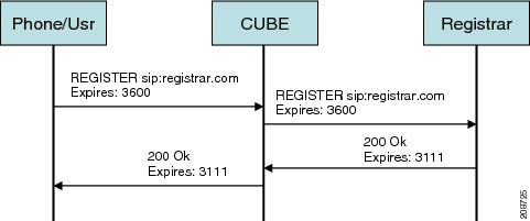
The register success scenario for the end-to end registration pass-through mode is as follows:
1. ![]() The user sends the register request to Cisco UBE.
The user sends the register request to Cisco UBE.
2. ![]() Cisco UBE matches the request with a dial peer and forwards the request to the registrar.
Cisco UBE matches the request with a dial peer and forwards the request to the registrar.
3. ![]() Cisco UBE receives a success response message (200 OK message) from the registrar and forwards the message to the endpoint (user).
Cisco UBE receives a success response message (200 OK message) from the registrar and forwards the message to the endpoint (user).
4. ![]() The registrar details and expiry value are passed to the user.
The registrar details and expiry value are passed to the user.
Registrar Challenging the Register Request Scenario
Figure 10 shows an end-to end registration pass-through scenario where the registrar challenges the register request.
Figure 10 End-to-End Registration Pass-through Mode—Registrar Challenging the Register Request Scenario
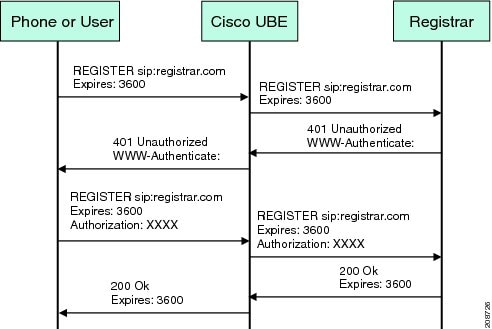
The following scenario explains how the registrar challenges the register request:
1. ![]() The user sends the register request to Cisco UBE.
The user sends the register request to Cisco UBE.
2. ![]() Cisco UBE matches the register request with a dial peer and forwards it to the registrar.
Cisco UBE matches the register request with a dial peer and forwards it to the registrar.
3. ![]() The registrar challenges the register request.
The registrar challenges the register request.
4. ![]() Cisco UBE passes the registrar response and the challenge request, only if the registrar challenges the request to the user.
Cisco UBE passes the registrar response and the challenge request, only if the registrar challenges the request to the user.
5. ![]() The user sends the register request and the challenge response to the Cisco UBE.
The user sends the register request and the challenge response to the Cisco UBE.
6. ![]() Cisco UBE forwards the response to the registrar.
Cisco UBE forwards the response to the registrar.
7. ![]() Cisco UBE receives success message (200 OK message) from the registrar and forwards it to the user.
Cisco UBE receives success message (200 OK message) from the registrar and forwards it to the user.
Peer-to-Peer Mode
In the peer-to-peer registration pass-through mode, the outgoing register request uses the registrar details from the local Cisco UBE configuration. Cisco UBE answers the challenges received from the registrar using the configurable authentication information. Cisco UBE can also challenge the incoming register requests and authenticate the requests before forwarding them to the network.
In this mode, Cisco UBE sends a register request to the registrar and also handles register request challenges. That is, if the registration request is challenged by the registrar (registrar sends 401 or 407 message), Cisco UBE forwards the challenge to the user and then passes the challenge response sent by the user to the registrar. In the peer-to-peer mode, Cisco UBE can use the authentication command to calculate the authorization header and then challenge the user depending on the configuration.
Note ![]() The registrar command must be configured in peer-to-peer mode. Otherwise, the register request is rejected with the 503 response message.
The registrar command must be configured in peer-to-peer mode. Otherwise, the register request is rejected with the 503 response message.
Peer-to-Peer Mode—Call Flows
This section explains the following peer-to-peer pass-through mode call flows:
•![]() Registrar Challenging the Register Request Scenario
Registrar Challenging the Register Request Scenario
Register Success Scenario
Figure 11 shows a peer-to-peer registration pass-through scenario where the registration request is successful.
Figure 11 Peer-to-Peer Registration Pass-through Mode—Register Success Scenario
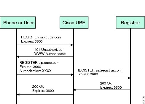
The register success scenario for a peer-to-peer registration pass-through mode is as follows:
1. ![]() The user sends the register request to Cisco UBE.
The user sends the register request to Cisco UBE.
2. ![]() Cisco UBE matches the register request with a dial peer and forwards the register request to the registrar.
Cisco UBE matches the register request with a dial peer and forwards the register request to the registrar.
3. ![]() Cisco UBE receives a success message (200 OK message) from the registrar and forwards it to the endpoint (user). The following functions are performed:
Cisco UBE receives a success message (200 OK message) from the registrar and forwards it to the endpoint (user). The following functions are performed:
–![]() Cisco UBE picks up the details about the registrar from the configuration.
Cisco UBE picks up the details about the registrar from the configuration.
–![]() Cisco UBE passes the registrar details and expiry value to the user.
Cisco UBE passes the registrar details and expiry value to the user.
Registrar Challenging the Register Request Scenario
Figure 12 shows a peer-to-peer registration pass-through scenario where the registration request is challenged by the registrar.
Figure 12 Peer-to-Peer Registration Pass-through Mode—Registrar Challenging the Register Request Scenario
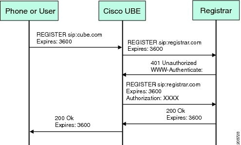
The following scenario explains how the registrar challenges the register request:
1. ![]() The user sends the register request to Cisco UBE.
The user sends the register request to Cisco UBE.
2. ![]() Cisco UBE matches the register request with a dial peer and forwards the register request to the registrar.
Cisco UBE matches the register request with a dial peer and forwards the register request to the registrar.
3. ![]() The user responds to the challenge request.
The user responds to the challenge request.
4. ![]() Cisco UBE validates the challenge response and forwards the register request to the registrar.
Cisco UBE validates the challenge response and forwards the register request to the registrar.
5. ![]() Cisco UBE receives a success message from the registrar and forwards it to the endpoint (user).
Cisco UBE receives a success message from the registrar and forwards it to the endpoint (user).
Note ![]() You can configure Cisco UBE to challenge the register request and validate the challenge response.
You can configure Cisco UBE to challenge the register request and validate the challenge response.
Registration in Different Registrar Modes
This section explains SIP registration pass-through in the following registrar modes:
Primary-Secondary Mode
In the primary-secondary mode the register message is sent to both the primary and the secondary registrar servers simultaneously.
The register message is processed as follows:
•![]() The first successful response is passed to the phone as a SUCCESS message.
The first successful response is passed to the phone as a SUCCESS message.
•![]() All challenges to the request are handled by Cisco UBE.
All challenges to the request are handled by Cisco UBE.
•![]() If the final response received from the primary and the secondary servers is an error response, the error response that arrives later from the primary or the secondary server is passed to the phone.
If the final response received from the primary and the secondary servers is an error response, the error response that arrives later from the primary or the secondary server is passed to the phone.
•![]() If only one registrar is configured, a direct mapping is performed between the primary and the secondary server.
If only one registrar is configured, a direct mapping is performed between the primary and the secondary server.
•![]() If no registrar is configured, or if there is a Domain Name System (DNS) failure, the "503 service not available" message is sent to the phone.
If no registrar is configured, or if there is a Domain Name System (DNS) failure, the "503 service not available" message is sent to the phone.
DHCP Mode
In the DHCP mode the register message is sent to the registrar server using DHCP.
Multiple Register Mode
In the multiple register mode, you can configure a dial peer to select and enable the indexed registrars. Register messages must be sent only to the specified index registrars.
The response from the registrar is mapped the same way as in the primary-secondary mode. See the "Primary-Secondary Mode" section.
Registration Overload Protection
The registration overload protection functionality enables Cisco UBE to reject the registration requests that exceed the configured threshold value.
To support the registration overload protection functionality, Cisco UBE maintains a global counter to count all the pending outgoing registrations and prevents the overload of the registration requests as follows:
•![]() The registration count is decremented if the registration transaction is terminated.
The registration count is decremented if the registration transaction is terminated.
•![]() The outgoing registrations are rejected if the count goes beyond a configured threshold.
The outgoing registrations are rejected if the count goes beyond a configured threshold.
•![]() The incoming register request is rejected with the 503 response if the outgoing registration is activated by the incoming register request.
The incoming register request is rejected with the 503 response if the outgoing registration is activated by the incoming register request.
•![]() A retry timer set for a random value is used for attempting the registration again if the registrations are originated from Cisco UBE or a gateway.
A retry timer set for a random value is used for attempting the registration again if the registrations are originated from Cisco UBE or a gateway.
The registration overload protection functionality protects the network from the following:
•![]() Avalanche Restart—All the devices in the network restart at the same time.
Avalanche Restart—All the devices in the network restart at the same time.
•![]() Component Failures—Sudden burst of load is routed through the device due to a device failure.
Component Failures—Sudden burst of load is routed through the device due to a device failure.
Registration Overload Protection—Call Flow
Figure 13 shows the call flow when the register overload protection functionality is configured on Cisco UBE:
Figure 13 Register Overload Protection
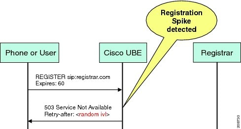
The following steps explain the register overload protection scenario:
1. ![]() The user sends a register request to Cisco UBE.
The user sends a register request to Cisco UBE.
2. ![]() Cisco UBE matches the request with a dial peer and forwards the register request to the registrar.
Cisco UBE matches the request with a dial peer and forwards the register request to the registrar.
3. ![]() The registration is rejected with a random retry value when the registration threshold value is reached.
The registration is rejected with a random retry value when the registration threshold value is reached.
Note ![]() The call flow for the DNS query on the Out Leg is the same for the end-to-end and peer-to-peer mode.
The call flow for the DNS query on the Out Leg is the same for the end-to-end and peer-to-peer mode.
Registration Rate-limiting
The registration rate-limiting functionality enables you to configure different SIP registration pass-through rate-limiting options. The rate-limiting options include setting the expiry time and the fail count value for a Cisco UBE. You can configure the expiry time to reduce the load on the registrar and the network. Cisco UBE limits the reregistration rate by maintaining two different timers—in-registration timer and out-registration timer.
The initial registration is triggered based on the incoming register request. The expiry value for the outgoing register is selected based on the Cisco UBE configuration. On receiving the 200 OK message (response to the BYE message) from the registrar, a timer is started using the expiry value available in the 200 OK message. The timer value in the 200 OK message is called the out-registration timer. The success response is forwarded to the user. The expiry value is taken from the register request and the timer is started accordingly. This timer is called the in-registration timer. There must be a significant difference between the in-registration timer and the out-registration timer values for effective rate-limiting.
Registration Rate-limiting Success—Call Flow
Figure 14 shows the call flow when the rate-limiting functionality is successful:
Figure 14 Rate-limiting Success Scenario

The following steps explain a scenario where the rate-limiting functionality is successful:
1. ![]() The user sends the register request to Cisco UBE.
The user sends the register request to Cisco UBE.
2. ![]() Cisco UBE matches the registration request with a dial peer and forwards it to the registrar. The outgoing register request contains the maximum expiry value if the rate-limiting functionality is configured.
Cisco UBE matches the registration request with a dial peer and forwards it to the registrar. The outgoing register request contains the maximum expiry value if the rate-limiting functionality is configured.
3. ![]() The registrar accepts the registration.
The registrar accepts the registration.
4. ![]() Cisco UBE forwards the success response with the proposed expiry timer value.
Cisco UBE forwards the success response with the proposed expiry timer value.
5. ![]() The user sends the reregistration requests based on the negotiated value. Cisco UBE resends the register requests until the out-leg expiry timer value is sent.
The user sends the reregistration requests based on the negotiated value. Cisco UBE resends the register requests until the out-leg expiry timer value is sent.
6. ![]() Cisco UBE forwards the subsequent register request to the registrar, if the reregister request is received after the out-leg timer is reached.
Cisco UBE forwards the subsequent register request to the registrar, if the reregister request is received after the out-leg timer is reached.
Prerequisites
•![]() You must enable the local SIP registrar. See "Enabling Local SIP Registrar" section.
You must enable the local SIP registrar. See "Enabling Local SIP Registrar" section.
•![]() You must configure dial peers manually for call routing and pattern matching.
You must configure dial peers manually for call routing and pattern matching.
Restrictions
IPv6 support is not provided.
Configuring Support for SIP Registration Proxy on Cisco UBE
•![]() Enabling Local SIP Registrar (required)
Enabling Local SIP Registrar (required)
•![]() Configuring SIP Registration at the Global Level (required)
Configuring SIP Registration at the Global Level (required)
•![]() Configuring SIP Registration at the Dial Peer Level (required)
Configuring SIP Registration at the Dial Peer Level (required)
•![]() Configuring Registration Overload Protection Functionality (optional)
Configuring Registration Overload Protection Functionality (optional)
•![]() Configuring Cisco UBE to Route a Call to the Registrar Endpoint (optional)
Configuring Cisco UBE to Route a Call to the Registrar Endpoint (optional)
•![]() Configuring Cisco UBE to Challenge Incoming Requests (optional)
Configuring Cisco UBE to Challenge Incoming Requests (optional)
•![]() Verifying the SIP Registration on Cisco UBE (optional)
Verifying the SIP Registration on Cisco UBE (optional)
Enabling Local SIP Registrar
Perform this task to enable the local SIP registrar.
SUMMARY STEPS
1. ![]() enable
enable
2. ![]() configure terminal
configure terminal
3. ![]() voice service voip
voice service voip
4. ![]() sip
sip
5. ![]() registrar server [expires [max value] [min value]]
registrar server [expires [max value] [min value]]
6. ![]() end
end
DETAILED STEPS
Configuring SIP Registration at the Global Level
Perform this task to configure the support for the SIP registration proxy on the Cisco UBE at the global level.
SUMMARY STEPS
1. ![]() enable
enable
2. ![]() configure terminal
configure terminal
3. ![]() voice service voip
voice service voip
4. ![]() sip
sip
5. ![]() registration passthrough [static] [rate-limit [expires value] [fail-count value]] [registrar-index [index]]
registration passthrough [static] [rate-limit [expires value] [fail-count value]] [registrar-index [index]]
6. ![]() end
end
DETAILED STEPS
Configuring SIP Registration at the Dial Peer Level
Perform this task to configure SIP registration at the dial peer level.
SUMMARY STEPS
1. ![]() enable
enable
2. ![]() configure terminal
configure terminal
3. ![]() dial-peer voice tag {pots | voatm | vofr | voip}
dial-peer voice tag {pots | voatm | vofr | voip}
4. ![]() voice-class sip registration passthrough static [rate-limit [expires value] [fail-count value] [registrar-index [index]] | registrar-index [index]]
voice-class sip registration passthrough static [rate-limit [expires value] [fail-count value] [registrar-index [index]] | registrar-index [index]]
5. ![]() exit
exit
DETAILED STEPS
Configuring Registration Overload Protection Functionality
Perform this task to configure registration overload protection functionality on Cisco UBE.
SUMMARY STEPS
1. ![]() enable
enable
2. ![]() configure terminal
configure terminal
3. ![]() sip-ua
sip-ua
4. ![]() registration spike max-number
registration spike max-number
5. ![]() end
end
DETAILED STEPS
Configuring Cisco UBE to Route a Call to the Registrar Endpoint
Perform this task to configure Cisco UBE to route a call to the registrar endpoint.
Note ![]() You must perform this configuration on a dial peer that is pointing towards the endpoint.
You must perform this configuration on a dial peer that is pointing towards the endpoint.
SUMMARY STEPS
1. ![]() enable
enable
2. ![]() configure terminal
configure terminal
3. ![]() dial-peer voice tag {pots | voatm | vofr | voip}
dial-peer voice tag {pots | voatm | vofr | voip}
4. ![]() session target registrar
session target registrar
5. ![]() exit
exit
DETAILED STEPS
Configuring Cisco UBE to Challenge Incoming Requests
Perform this task to configure Cisco UBE to challenge incoming requests.
You can configure Cisco UBE to challenge an incoming request. That is, you can configure Cisco UBE to send the 401 or 407 message to the caller requesting for credentials. Based on the information received, Cisco UBE authenticates the request. The configuration also enables Cisco UBE to pass the credentials provided by the user to the registrar if the registrar has challenged the request.
SUMMARY STEPS
1. ![]() enable
enable
2. ![]() configure terminal
configure terminal
3. ![]() dial-peer voice tag {pots | voatm | vofr | voip}
dial-peer voice tag {pots | voatm | vofr | voip}
4. ![]() authentication username username password [0 | 7] password [realm realm [challenge]]
authentication username username password [0 | 7] password [realm realm [challenge]]
5. ![]() exit
exit
DETAILED STEPS
Verifying the SIP Registration on Cisco UBE
Perform this task to verify the configuration for SIP registration on Cisco UBE. The show commands need not be entered in any specific order.
SUMMARY STEPS
1. ![]() enable
enable
2. ![]() show sip-ua registration passthrough status
show sip-ua registration passthrough status
3. ![]() show sip-ua registration passthrough status detail
show sip-ua registration passthrough status detail
DETAILED STEPS
Step 1 ![]() enable
enable
Enables privileged EXEC mode.
Router> enable
Step 2 ![]() show sip-ua registration passthrough status
show sip-ua registration passthrough status
Displays the SIP user agent (UA) registration pass-through status information.
Router# show sip-ua registration passthrough status
CallId Line peer mode In-Exp reg-I Out-Exp
============ ============ ============ ==== ============ ===== ============
771 5500550055 1 p2p 64 1 64
=============================================================================
Step 3 ![]() show sip-ua registration passthrough status detail
show sip-ua registration passthrough status detail
Displays the SIP UA registration pass-through status information in detail.
Router# show sip-ua registration passthrough status detail
============================================================
Configured Reg Spike Value: 0
Number of Pending Registrations: 0
============================================================
Call-Id: 763
Registering Number: 5500550055
Dial-peer tag: 601
Pass-through Mode: p2p
Negotiated In-Expires: 64 Seconds
Next In-Register Due in: 59 Seconds
In-Register Contact: 9.45.36.5
----------------------------------------
Registrar Index: 1
Registrar URL: ipv4:9.45.36.4
Negotiated Out-Expires: 64 Seconds
Next Out-Register After: 0 Seconds
============================================================
Configuring Support for Conditional Header Manipulation of SIP Headers
The Support for Conditional Header Manipulation of SIP Headers feature provides the following enhancements to Cisco Unified Border Element (Cisco UBE):
•![]() The ability to pass unsupported parameters present in a mandatory Session Initiation Protocol (SIP) header from one call leg to another of Cisco UBE.
The ability to pass unsupported parameters present in a mandatory Session Initiation Protocol (SIP) header from one call leg to another of Cisco UBE.
•![]() The ability to copy contents from one header to another in an outgoing SIP message.
The ability to copy contents from one header to another in an outgoing SIP message.
Restrictions
•![]() You cannot configure more than 99 variables for the SIP profiles copy option.
You cannot configure more than 99 variables for the SIP profiles copy option.
•![]() This feature does not support any header other than SIP.
This feature does not support any header other than SIP.
Passing an Unsupported Parameter Present in a Mandatory Header from One Call Leg to Another of Cisco UBE
Perform this task to pass an unsupported parameter present in a mandatory header from one call leg to another of Cisco UBE.
SUMMARY STEPS
1. ![]() enable
enable
2. ![]() configure terminal
configure terminal
3. ![]() voice class sip-copylist tag
voice class sip-copylist tag
4. ![]() sip-header {sip-req-uri | header-name}
sip-header {sip-req-uri | header-name}
5. ![]() exit
exit
DETAILED STEPS
Copying Contents from One Header to Another in an Outgoing SIP Message
Perform the following tasks to copy contents from one header to another in an outgoing SIP message:
•![]() Copying Contents from One SIP Header to Another in an Outgoing Message (required)
Copying Contents from One SIP Header to Another in an Outgoing Message (required)
•![]() Copying Contents from Peer Header to a SIP Header in an Outgoing Message (required)
Copying Contents from Peer Header to a SIP Header in an Outgoing Message (required)
Copying Contents from One SIP Header to Another in an Outgoing Message
Perform this task to copy contents from one SIP to another in an outgoing message.
SUMMARY STEPS
1. ![]() enable
enable
2. ![]() configure terminal
configure terminal
3. ![]() voice class sip-profiles tag
voice class sip-profiles tag
4. ![]() request method sip-header field {add | copy | modify | remove} string
request method sip-header field {add | copy | modify | remove} string
5. ![]() response option sip-header field {add | copy | modify | remove} string
response option sip-header field {add | copy | modify | remove} string
6. ![]() exit
exit
DETAILED STEPS
Copying Contents from Peer Header to a SIP Header in an Outgoing Message
Perform this task to copy contents from peer header to a SIP header in an outgoing message.
SUMMARY STEPS
1. ![]() enable
enable
2. ![]() configure terminal
configure terminal
3. ![]() voice class sip-profiles tag
voice class sip-profiles tag
4. ![]() request method peer-header sip {sip-req-uri | header-name} copy match-pattern variable
request method peer-header sip {sip-req-uri | header-name} copy match-pattern variable
5. ![]() response option peer-header sip {sip-req-uri | header-name} copy match-pattern variable
response option peer-header sip {sip-req-uri | header-name} copy match-pattern variable
6. ![]() exit
exit
DETAILED STEPS
Configuring Support for Reporting End-of-Call Statistics in SIP BYE Message
The Support for Reporting End-of-Call Statistics in Session Initiation Protocol (SIP) BYE Message feature enables you to send call statistics to a remote end when a call terminates. The call statistics are sent as a new header in the BYE message or in the 200 OK message (response to BYE message). The statistics include Real-time Transport Protocol (RTP) packets sent or received, total bytes sent or received, total number of packets that are lost, delay jitter, round-trip delay, and the call duration.
This feature enables Cisco Unified Border Element (Cisco UBE) to use the call statistics to update the call data records in Cisco Unified Communications Manager (Cisco UCM) or Cisco Unified Communications Manager Express (Cisco UCME).
The Support for Reporting End-of-Call Statistics in SIP BYE Message feature is enabled bu default on Cisco UBE.
A new header P-RTP-Stat is added to the BYE and 200 OK messages. The format of P-RTP-Stat is as follows:
P-RTP-Stat: PS=<Packets Sent>, OS=<Octets Sent>, PR=<Packets Recd>, OR=<Octets Recd>, PL=<Packets Lost>, JI=<Jitter>, LA=<Round Trip Delay in ms>, DU=<Call Duration in seconds>
Table 4 describes the P-RTP-Stat header field description.
Figure 15
P-RTP-Stat Header Fields
Restrictions
•![]() If the media flow-around command is configured, the call statistics are not sent for a 200 OK message.
If the media flow-around command is configured, the call statistics are not sent for a 200 OK message.
•![]() If the media flow-around command is configured, the call statistics are passed through the Cisco UBE for a BYE message.
If the media flow-around command is configured, the call statistics are passed through the Cisco UBE for a BYE message.
•![]() The values are not validated when the incoming statistics are passed to the endpoints. Hence, in some cases the values may be invalid.
The values are not validated when the incoming statistics are passed to the endpoints. Hence, in some cases the values may be invalid.
•![]() The value of round-trip delay is valid only if the remote end supports Real-Time Control Protocol (RTCP).
The value of round-trip delay is valid only if the remote end supports Real-Time Control Protocol (RTCP).
Disabling Support for Reporting End-of-Call Statistics in SIP BYE Message feature
The Support for Reporting End-of-Call Statistics in SIP BYE Message feature is enabled by default on the Cisco UBE. That is, the P-RTP-Stat header is added to the list of headers that can be processed through the SIP profiles. You must apply SIP profile rules to remove the header from the mandatory header list.
This section contains the following tasks:
•![]() Defining SIP Profile Rules to Remove a Header (required)
Defining SIP Profile Rules to Remove a Header (required)
•![]() Disabling Support for Reporting End-of-Call Statistics in SIP BYE Message at the Global Level (optional)
Disabling Support for Reporting End-of-Call Statistics in SIP BYE Message at the Global Level (optional)
•![]() Disabling Support for Reporting End-of-Call Statistics in SIP BYE Message at the Dial Peer Level (optional)
Disabling Support for Reporting End-of-Call Statistics in SIP BYE Message at the Dial Peer Level (optional)
Defining SIP Profile Rules to Remove a Header
Perform this task to define SIP profile rules to remove a header.
SUMMARY STEPS
1. ![]() enable
enable
2. ![]() configure terminal
configure terminal
3. ![]() voice class sip-profiles tag
voice class sip-profiles tag
4. ![]() request bye sip-header p-rtp-stat remove
request bye sip-header p-rtp-stat remove
5. ![]() response 200 sip-header p-rtp-stat remove
response 200 sip-header p-rtp-stat remove
6. ![]() exit
exit
DETAILED STEPS
Disabling Support for Reporting End-of-Call Statistics in SIP BYE Message at the Global Level
Perform this task to disable the Support for Reporting End-of-Call Statistics in SIP BYE Message feature at the global level.
The Support for Reporting End-of-Call Statistics in SIP BYE Message feature is enabled by default on Cisco UBE. Hence, to disable the feature, you must modify the SIP profiles to remove the P-RTP-Stat SIP header from the request and the response messages and then configure the modified SIP profile on the Cisco UBE.
SUMMARY STEPS
1. ![]() enable
enable
2. ![]() configure terminal
configure terminal
3. ![]() voice service voip
voice service voip
4. ![]() sip
sip
5. ![]() sip-profiles tag
sip-profiles tag
6. ![]() exit
exit
DETAILED STEPS
|
|
|
|
|---|---|---|
Step 1 |
enable Router> enable |
Enables privileged EXEC mode. • |
Step 2 |
configure terminal Router# configure terminal |
Enters global configuration mode. |
Step 3 |
voice service voip Router(config)# voice service voip |
Specifies VoIP as the voice encapsulation method and enters voice-service configuration mode. |
Step 4 |
sip Router(conf-voi-serv)# sip |
Enters service SIP configuration mode. |
Step 5 |
sip-profiles tag Router(conf-serv-sip)# sip-profiles 100 |
Disables the Support for Reporting End-of-Call Statistics in SIP BYE Message feature at the global level. • |
Step 6 |
exit Router(config-class)# exit |
Exits service SIP configuration mode. |
Disabling Support for Reporting End-of-Call Statistics in SIP BYE Message at the Dial Peer Level
Perform this task to disable the Support for Reporting End-of-Call Statistics in SIP BYE Message feature at the dial peer level.
The Support for Reporting End-of-Call Statistics in SIP BYE Message feature is enabled by default. Hence to disable the feature, you must modify the SIP profiles to remove the P-RTP-Stat SIP header from the request and the response messages and then configure the modified SIP profile on the Cisco UBE.
SUMMARY STEPS
1. ![]() enable
enable
2. ![]() configure terminal
configure terminal
3. ![]() dial-peer voice tag voip
dial-peer voice tag voip
4. ![]() voice-class sip profiles tag
voice-class sip profiles tag
5. ![]() exit
exit
DETAILED STEPS
|
|
|
|
|---|---|---|
Step 1 |
enable Router> enable |
Enables privileged EXEC mode. • |
Step 2 |
configure terminal Router# configure terminal |
Enters global configuration mode. |
Step 3 |
dial-peer voice tag voip Router(config)# dial-peer voice 100 voip |
Defines a dial peer to specify the method of voice encapsulation and enters dial peer configuration mode. |
Step 4 |
voice-class sip profiles tag Router(config-dial-peer)# voice-class sip profiles 100 |
Disables the Support for Reporting End-of-Call Statistics in SIP BYE Message feature at the dial peer level. • |
Step 5 |
exit Router(config-dial-peer)# exit |
Exits dial peer configuration mode. |
Configuring RTP Media Loopback for SIP Calls
RTP packets are looped back toward the source device when the RTP Media Loopback for SIP Calls feature is configured on a dial peer. The SIP RTP media loopback can be used during Cisco UBE deployments to make test calls to verify the media path between the endpoints and Cisco UBE. In a voice loopback call, an echo is heard at the device originating the call. In a video loopback call, the locally captured video and the audio echo must be rendered at the source device.
Prerequisites for Configuring RTP Media Loopback for SIP Calls
Media packets must be enabled to pass through the gateway. Use the media flow-through command in dial peer voice or voice service configuration mode to enable the media packets.
Restrictions for Configuring RTP Media Loopback for SIP Calls
•![]() SRTP, DTLS, and STUN are not supported in loopback mode.
SRTP, DTLS, and STUN are not supported in loopback mode.
•![]() Fax (midcall transmit function change) is not supported.
Fax (midcall transmit function change) is not supported.
•![]() RSVP is not supported.
RSVP is not supported.
•![]() Call transfer is not supported.
Call transfer is not supported.
SUMMARY STEPS
1. ![]() enable
enable
2. ![]() configure terminal
configure terminal
3. ![]() dial-peer voice tag voip
dial-peer voice tag voip
4. ![]() destination-pattern string
destination-pattern string
5. ![]() session protocol sipv2
session protocol sipv2
6. ![]() session target loopback:rtp
session target loopback:rtp
7. ![]() incoming called-number string
incoming called-number string
8. ![]() exit
exit
DETAILED STEPS
Configuration Examples for RTP Media Loopback
This section provides the following examples:
•![]() Example: Configuring Video Loopback with Cisco Telepresence System
Example: Configuring Video Loopback with Cisco Telepresence System
•![]() Example: Configuring Video Loopback with Cisco Unified Video Advantage (CUVA)
Example: Configuring Video Loopback with Cisco Unified Video Advantage (CUVA)
Example: Configuring Video Loopback with Cisco Telepresence System
The following sample output shows Media Loopback for SIP Calls configured on a Cisco Telepresence System (CTS).
!
codec profile 1 aacld
 fmtp "fmtp:96
profile-level-id=16;streamtype=5;mode=AAChbr;config=B98C00;sizeLength=13;indexLength=3;ind
exDeltaLength=3;constantDura
tion=480"
!
codec profile 2 h264
fmtp "fmtp:112 profile-level-id=4D0028;sprop-parametersets=
R00AKAmWUgDwBDyA,SGE7jyA=;packetization-mode=1"
!
voice class codec 4
codec preference 1 aacld profile 1
video codec h264 profile 2
!
dial-peer voice 2000 voip
destination-pattern 2000
rtp payload-type cisco-codec-fax-ind 110
rtp payload-type cisco-codec-aacld 96
rtp payload-type cisco-codec-video-h264 112
session protocol sipv2
session target loopback:rtp
incoming called-number 2000
voice-class codec 4
voice-class sip bandwidth audio tias-modifier 64000
voice-class sip bandwidth video tias-modifier 4500000
!
Example: Configuring Video Loopback with Cisco Unified Video Advantage (CUVA)
The following sample output shows Media Loopback for SIP Calls configured on a Cisco Unified Video Advantage (CUVA).
!
codec profile 3 h264
fmtp "fmtp:98 profile-level-id=420015"
!
voice class codec 6
codec preference 1 g711ulaw
video codec h264 profile 3
!
dial-peer voice 5000 voip
description CUVA
destination-pattern 5000
rtp payload-type cisco-codec-video-h264 98
session protocol sipv2
session target loopback:rtp
incoming called-number 5000
voice-class codec 6
voice-class sip bandwidth video tias-modifier 384000
Verifying and Troubleshooting SIP-to-SIP Connections on a Cisco Unified Border Element
To troubleshoot or verify connections in an Cisco UBE, perform the following task:
•![]() Verifying SIP-to-SIP Connections in an Cisco Unified Border Element
Verifying SIP-to-SIP Connections in an Cisco Unified Border Element
Troubleshooting Tips
•![]() Use the debug voip ipipgw command to debug the Cisco Unified Border Element feature.
Use the debug voip ipipgw command to debug the Cisco Unified Border Element feature.
•![]() Use any of the following additional commands on the gateway as appropriate to troubleshoot SIP-to-SIP call scenarios:
Use any of the following additional commands on the gateway as appropriate to troubleshoot SIP-to-SIP call scenarios:
–![]() debug ccsip all
debug ccsip all
–![]() debug voip ccapi inout
debug voip ccapi inout
Note ![]() For examples of show and debug command output and details on interpreting the output, see the following resources:
For examples of show and debug command output and details on interpreting the output, see the following resources:
•![]() Cisco IOS Debug Command Reference, Release 12.4T
Cisco IOS Debug Command Reference, Release 12.4T
•![]() Cisco IOS Voice Troubleshooting and Monitoring Guide
Cisco IOS Voice Troubleshooting and Monitoring Guide
•![]() Troubleshooting and Debugging VoIP Call Basics
Troubleshooting and Debugging VoIP Call Basics
Verifying SIP-to-SIP Connections in an Cisco Unified Border Element
To verify SIP-to-SIP feature configuration and operation, perform the following steps (listed alphabetically) as appropriate.
SUMMARY STEPS
1. ![]() show call active video
show call active video
2. ![]() show call active voice
show call active voice
3. ![]() show call history fax
show call history fax
4. ![]() show call history video
show call history video
5. ![]() show call history voice
show call history voice
6. ![]() show crm
show crm
7. ![]() show dial-peer voice
show dial-peer voice
8. ![]() show running-config
show running-config
9. ![]() show voip rtp connections
show voip rtp connections
DETAILED STEPS
Step 1 ![]() show call active video
show call active video
Use this command to display the active video H.323 call legs.
Step 2 ![]() show call active voice
show call active voice
Use this command to display call information for voice calls that are in progress.
Step 3 ![]() show call active fax
show call active fax
Use this command to display the fax transmissions that are in progress.
Step 4 ![]() show call history video
show call history video
Use this command to display the history of video H.323 call legs.
Step 5 ![]() show call history voice
show call history voice
Use this command to display the history of voice call legs.
Step 6 ![]() show call history fax
show call history fax
Use this command to display the call history table for fax transmissions that are in progress.
Step 7 ![]() show crm
show crm
Use this command to display the carrier ID list or IP circuit utilization.
Step 8 ![]() show dial-peer voice
show dial-peer voice
Use this command to display information about voice dial peers.
Step 9 ![]() show running-config
show running-config
Use this command to verify which H.323-to-H.323, H.323-to-SIP, or SIP-to-SIP connection types are supported.
Step 10 ![]() show voip rtp connections
show voip rtp connections
Use this command to display active Real-Time Transport Protocol (RTP) connections.
Configuration Examples for SIP-to-SIP Connections in a Cisco Unified Border Element
This section contains the following examples:
•![]() Basic SIP-to-SIP Call Flow: Example
Basic SIP-to-SIP Call Flow: Example
•![]() SRTP-RTP Internetworking: Example
SRTP-RTP Internetworking: Example
•![]() Example: Configuring Support for SIP Registration Proxy on Cisco UBE
Example: Configuring Support for SIP Registration Proxy on Cisco UBE
Basic SIP-to-SIP Call Flow: Example
The following scenario illustrates a basic SIP-to-SIP call flow, using the Cisco Unified Border Element.
Figure 16 shows a simple topology example of the SIP-to-SIP gateway topology.
Figure 16 Cisco Unified Border Element Feature Sample Topology
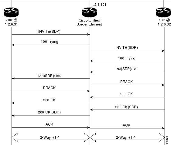
Call Flow
•![]() The Cisco UBE receives INVITE with Session Description Protocol (SDP) from the OGW. The SDP contains information about the capabilities the endpoint supports for this call like the Audio Codec's, DTMF etc.
The Cisco UBE receives INVITE with Session Description Protocol (SDP) from the OGW. The SDP contains information about the capabilities the endpoint supports for this call like the Audio Codec's, DTMF etc.
•![]() The Codec and DTMF type received from OGW is matched with the incoming configured or default dial-peer.
The Codec and DTMF type received from OGW is matched with the incoming configured or default dial-peer.
•![]() The SGW responds to the INVITE message from the OGW by sending a 100 Trying message to OGW.
The SGW responds to the INVITE message from the OGW by sending a 100 Trying message to OGW.
•![]() The Matched Capabilities are sent to the application which forwards the Matched Capabilities to the outbound SPI.
The Matched Capabilities are sent to the application which forwards the Matched Capabilities to the outbound SPI.
•![]() The application receives the Matched Capabilities.
The application receives the Matched Capabilities.
•![]() The Codec Type and DTMF type is selected and SDP is formed based on the outgoing dial-peer configured capabilities, and the capabilities received from the application.
The Codec Type and DTMF type is selected and SDP is formed based on the outgoing dial-peer configured capabilities, and the capabilities received from the application.
•![]() The Cisco UBE sends an Invite with SDP to the TGW.
The Cisco UBE sends an Invite with SDP to the TGW.
•![]() The TGW responds to the Cisco UBE with a 100 Trying message.
The TGW responds to the Cisco UBE with a 100 Trying message.
•![]() The TGW sends 183 (SDP) if the Phone type on TGW is POTS or 180 if the Phone type on TGW is SIP /SCCP Phone to the Cisco UBE.
The TGW sends 183 (SDP) if the Phone type on TGW is POTS or 180 if the Phone type on TGW is SIP /SCCP Phone to the Cisco UBE.
•![]() Cisco UBE sends a PRACK Message to the TGW.
Cisco UBE sends a PRACK Message to the TGW.
•![]() OGW receives 183(SDP)/180 from the Cisco UBE.
OGW receives 183(SDP)/180 from the Cisco UBE.
•![]() TGW sends 200 Ok to the Cisco UBE.
TGW sends 200 Ok to the Cisco UBE.
•![]() Cisco UBE receives a PRACK message from the OGW.
Cisco UBE receives a PRACK message from the OGW.
•![]() OGW receives 200 Ok from the Cisco UBE.
OGW receives 200 Ok from the Cisco UBE.
•![]() The TGW sends 200 Ok with SDP to the Cisco UBE.
The TGW sends 200 Ok with SDP to the Cisco UBE.
•![]() Cisco UBE sends 200 Ok with SDP to the OGW.
Cisco UBE sends 200 Ok with SDP to the OGW.
•![]() OGW sends ACK to the Cisco UBE.
OGW sends ACK to the Cisco UBE.
•![]() Cisco UBE sends ACK towards TGW only after it receives ACK from the OGW.
Cisco UBE sends ACK towards TGW only after it receives ACK from the OGW.
•![]() Two-phase exchange provides negotiation capabilities based on simple offer/answer model of SDP exchange
Two-phase exchange provides negotiation capabilities based on simple offer/answer model of SDP exchange
•![]() The Contact header field should always carry the address of Cisco UBE and in none of the messages the IP address on one service provider should be sent to other.
The Contact header field should always carry the address of Cisco UBE and in none of the messages the IP address on one service provider should be sent to other.
INVITE message received from OGW has Contact: <sip:70005@1.2.6.31:5060>
INVITE message sent from Cisco UBE has Contact: <sip:70005@1.2.6.101:5060>
The same applies to the Contact address when sending response messages towards OGW.
Table 5 shows support for Early Media and their supported Codec and packetization values.
Transparent Codec
Most video endpoints have proprietary codecs for both audio and video. This makes transparent codecs are most important when handling video calls. If Codec T is configured under the dial-peer all the audio capabilities are transparently passed from one leg to another. Codecs that are not supported by the platform are also passed from incoming leg to outgoing leg.
|
|
|
|
|---|---|---|
H.323 |
H.323 |
Yes |
Note ![]() If both g79r8 and g729br8 is configured using voice class Codec then g729br8 is only codec sent in INVITE.
If both g79r8 and g729br8 is configured using voice class Codec then g729br8 is only codec sent in INVITE.
INVITE message contains
m=audio 19078 RTP/AVP 18 101 19
c=IN IP4 1.5.5.2
a=rtpmap:18 G729/8000
a=fmtp:18 annexb=yes
•![]() if TGW sends in session progress G729r8 then G.729r8 is the negotiated codec.
if TGW sends in session progress G729r8 then G.729r8 is the negotiated codec.
•![]() if TGW sends in session progress G729br8 then G.729br8 is the negotiated codec.
if TGW sends in session progress G729br8 then G.729br8 is the negotiated codec.
Packetization
The packetization values with different codecs are sent to Cisco UBE with attribute "ptime". The Cisco UBE should ensure that the packetization value received from OGW is sent to TGW.
For example: ptime = 10 is sent when g711ulaw is configured 80 bytes.
SRTP-RTP Internetworking: Example
The following example shows how to configure Cisco Unified Border Element support for SRTP-RTP internetworking. In this example, the incoming call leg is RTP and the outgoing call leg is SRTP.
enable
configure terminal
ip http server
crypto pki server 3845-cube
database level complete
grant auto
no shutdown
%PKI-6-CS_GRANT_AUTO: All enrollment requests will be automatically granted.
% Some server settings cannot be changed after CA certificate generation.
% Please enter a passphrase to protect the private key or type Return to exit
Password:
Re-enter password:
% Generating 1024 bit RSA keys, keys will be non-exportable...[OK]
% SSH-5-ENABLED: SSH 1.99 has been enabled
% Exporting Certificate Server signing certificate and keys...
% Certificate Server enabled.
%PKI-6-CS_ENABLED: Certificate server now enabled.
!
crypto pki trustpoint secdsp
enrollment url http://10.13.2.52:80
serial-number
revocation-check crl
rsakeypair 3845-cube
exit
!
crypto pki authenticate secdsp
Certificate has the following attributes:
Fingerprint MD5: CCC82E9E 4382CCFE ADA0EB8C 524E2FC1
Fingerprint SHA1: 34B9C4BF 4841AB31 7B0810AD 80084475 3965F140
% Do you accept this certificate? [yes/no]: yes
Trustpoint CA certificate accepted.
crypto pki enroll secdsp
% Start certificate enrollment ..
% Create a challenge password. You will need to verbally provide this password to the CA
Administrator in order to revoke your certificate. For security reasons your password will
not be saved in the configuration. Please make a note of it.
Password:
Re-enter password:
% The subject name in the certificate will include: 3845-CUBE
% The serial number in the certificate will be: FHK1212F4MU
% Include an IP address in the subject name? [no]:
Request certificate from CA? [yes/no]: yes
% Certificate request sent to Certificate Authority
% The 'show crypto pki certificate secdsp verbose' command will show the fingerprint.
CRYPTO_PKI: Certificate Request Fingerprint MD5: 56CE5FC3 B8411CF3 93A343DA 785C2360
CRYPTO_PKI:  Certificate Request Fingerprint SHA1: EE029629 55F5CA10 21E50F08 F56440A2
DDC7469D
%PKI-6-CERTRET: Certificate received from Certificate Authority
!
voice-card 0
dspfarm
dsp services dspfarm
voice-card 1
dspfarm
dsp services dspfarm
exit
!
sccp local GigabitEthernet 0/0
sccp ccm 10.13.2.52 identifier 1 version 5.0.1
sccp
SCCP operational state bring up is successful.sccp ccm group 1
associate ccm 1 priority 1
associate profile 1 register sxcoder
dspfarm profile 1 transcode universal security
trustpoint secdsp
codec g711ulaw
codec g711alaw
codec g729ar8
codec g729abr8
codec g729r8
codec ilbc
codec g729br8
maximum sessions 84
associate application sccp
no shutdown
exit
!
telephony-service
%LINEPROTO-5-UPDOWN: Line protocol on Interface EDSP0, changed state to upsdspfarm units 1
sdspfarm transcode sessions 84
sdspfarm tag 1 sxcoder
em logout 0:0 0:0 0:0
max-ephones 4
max-dn 4
ip source-address 10.13.2.52
Updating CNF files
CNF-FILES: Clock is not set or synchronized, retaining old versionStamps
CNF files updating complete
secure-signaling trustpoint secdsp
tftp-server-credentials trustpoint scme
CNF-FILES: Clock is not set or synchronized, retaining old versionStamps
CNF files update complete (post init)
create cnf-files
CNF-FILES: Clock is not set or synchronized, retaining old versionStamps
no sccp
!
sccp
SCCP operational state bring up is successful.
end
%SDSPFARM-6-REGISTER: mtp-1:sxcoder IP:10.13.2.52 Socket:1 DeviceType:MTP has registered.
%SYS-5-CONFIG_I: Configured from console by console
dial-peer voice 201 voip
destination-pattern 5550111
session protocol sipv2
session target ipv4:10.13.25.102
incoming called-number 5550112
codec g711ulaw
!
dial-peer voice 200 voip
destination-pattern 5550112
session protocol sipv2
session target ipv4:10.13.2.51
incoming called-number 5550111
srtp
codec g711ulaw
Example: Configuring Support for SIP Registration Proxy on Cisco UBE
The following example shows how to configure support for the SIP registration proxy on the Cisco UBE.
!
!
voice service voip
sip
registrar server expires max 121 min 61
  registration passthrough static challenge rate-limit expires 9000 fail-count 5
registrar-index 1 3 5
!
dial-peer voice 1111 voip
destination-pattern 1234
voice-class sip pass-thru content unsupp
session protocol sipv2
session target registrar
!
dial-peer voice 1111 voip
destination-pattern 1234
voice-class sip pass-thru content unsupp
 voice-class sip registration passthrough static rate-limit expires 9000 fail-count 5
registrar-index 1 3 5
authentication username 1234 password 7 075E731F1A realm cisco.com challenge
session protocol sipv2
session target registrar
!
sip-ua
registration spike 1000
!
!
Troubleshooting Tips
The following commands can help troubleshoot SIP-to-SIP calls on the Cisco UBE:
•![]() debug ccsip all
debug ccsip all
•![]() debug voip ccapi
debug voip ccapi
Where to Go Next
•![]() H.323-to-H.323 Connections on a Cisco Unified Border Element
H.323-to-H.323 Connections on a Cisco Unified Border Element
•![]() H.323-to-SIP Connections on a Cisco Unified Border Element
H.323-to-SIP Connections on a Cisco Unified Border Element
•![]() Configuring Cisco Unified Border Element Videoconferencing
Configuring Cisco Unified Border Element Videoconferencing
Additional References
The following sections provide references related to SIP-to-SIP Cisco Unified Border Element Connections
The following sections provide additional references related to the Cisco UBE Configuration Guide.
Note![]() •
•![]() In addition to the references listed below, each chapter provides additional references related to Cisco Unified Border Element.
In addition to the references listed below, each chapter provides additional references related to Cisco Unified Border Element.
•![]() Some of the products and services mentioned in this guide may have reached end of life, end of sale, or both. Details are available at http://www.cisco.com/en/US/products/prod_end_of_life.html.
Some of the products and services mentioned in this guide may have reached end of life, end of sale, or both. Details are available at http://www.cisco.com/en/US/products/prod_end_of_life.html.
•![]() The preface and glossary for the entire voice-configuration library suite of documents is listed below.
The preface and glossary for the entire voice-configuration library suite of documents is listed below.
Related Documents
Standards
|
|
|
|---|---|
H.323 Version 4 and earlier |
H.323 (ITU-T VOIP protocols) |
H.323 - H.245 Version 12, Annex R |
H.323 (ITU-T VOIP protocols) |
MIBs
RFCs
Technical Assistance
Feature Information for SIP-to-SIP Connections on a Cisco Unified Border Element
Table 7 lists the features in this module and provides links to specific configuration information.
For information on a feature in this technology that is not documented here, see the "Cisco Unified Border Element Features Roadmap."
Use Cisco Feature Navigator to find information about platform support and software image support. Cisco Feature Navigator enables you to determine which software images support a specific software release, feature set, or platform. To access Cisco Feature Navigator, go to http://www.cisco.com/go/cfn. An account on Cisco.com is not required.
Note ![]() Table 7 lists only the software release that introduced support for a given feature in a given software release train. Unless noted otherwise, subsequent releases of that software release train also support that feature.
Table 7 lists only the software release that introduced support for a given feature in a given software release train. Unless noted otherwise, subsequent releases of that software release train also support that feature.
|
|
|
|
|---|---|---|
Address Hiding |
12.4(9)T |
Address hiding in all SIP messages. The following section provides information about this feature: • The following command was modified: address-hiding. |
Adjustable Timers for Registration Refresh and Retries |
12.4(22)Y |
This feature provides the ability for Cisco IOS software to: • • • The following section provides information about this feature: • The following commands were introduced or modified: registrar and retry register. |
Allow Connections on a Cisco Unified Border Element |
12.3(1) |
H.323-to-H.323 gateway configuration provides a network-to-network demarcation point between independent VoIP and video networks for billing, security, call-admission control, QoS, and signaling interworking. The following section provides information about this feature: • The following command was modified: allow-connections. |
Assisted Real-time Transport Control Protocol (RTCP) Report Generation |
15.1(2)T |
This feature adds the ability for the Cisco UBE to generate standard RTCP keepalive reports on behalf of endpoints and ensures the liveliness of a media session during prolonged periods of silence, such as call hold. The following section provides information about this feature: • The following commands were introduced or modified: debug ip rtp protocol, debug voip rtcp, debug voip rtp, ip rtcp report interval, and rtcp keepalive. |
Call Admission Control |
12.4(6)T |
This feature enables the SIP-to-SIP functionality to conform with RFC 3261 to interoperate with SIP UAs based on CPU, memory, and total calls. |
Call Escalation from Voice to Video |
15.1(4)M |
This feature supports mid-call escalation of SIP-to-SIP calls via signaling from voice calls to video. The following section provides information about this feature: |
Calls for SIP and H.323 |
12.4(15)XY |
This feature was introduced. |
Cisco UBE MIB Support |
15.0(1)XA |
This feature was introduced. |
Cisco Unified Communications Manager Connections |
12.4(6)T |
Interoperability with Cisco Unified Communications Manager 5.0 and BroadSoft. |
Codec Support |
12.4(4)T |
In Cisco IOS Release 12.4(4)T, support for the SIP-to-SIP basic functionality for SBC for Cisco UBE was introduced. This functionality provides termination and reorigination of both signaling and media between VoIP and video networks using SIP signaling. In Cisco IOS Release 12.4(11)T, support for the iLBC codec was introduced. |
Configurable Bandwidth Parameters for SIP Calls |
12.4(15)XZ |
This feature provides the ability to manually configure the bandwidth that is signaled in the outbound SIP invite. |
Configurable SIP Parameters via DHCP |
12.4(22)YB |
The Configurable SIP Parameters via DHCP feature introduces the configuring of SIP parameters via DHCP. The following commands were introduced or modified: credentials (sip-ua), debug ccsip dhcp, dhcp interface, ip dhcp-client forcerenew, outbound-proxy, registrar, session target (VoIP dial peer), show sip dhcp, voice-class sip outbound-proxy. |
DTMF Relay |
12.4(4)T |
In Cisco IOS Release 12.4(4)T, support for the DTMF Relay Digit-Drop for SIP Calls Using NTE feature was introduced. In Cisco IOS Release 12.4(11)T, support for passing DTMF tones out-of-band and dropping in-band digits to avoid sending both tones to the outgoing leg on an H.323-to-SIP Cisco Unified Border Element was introduced. In Cisco IOS Release 12.4(6)XE, support for G.711 Inband DTMF to RFC 2833 was introduced. |
ENUM Support |
12.4(6)T |
This feature enables the SIP-to-SIP functionality to conform with RFC 3261 to interoperate with SIP UAs. |
Error Response Code upon an Out-of-Dialog OPTIONS Ping Failure |
15.0(1)XA |
This feature provides the option to configure the error response code when a dial peer is busied out because of an Out-of-Dialog OPTIONS ping failure. The following section provides information about this feature: • The following commands were introduced or modified: error-code-override options-keepalive failure, voice-class sip error-code-override options-keepalive failure. |
Fax/Modem |
12.4(6)T |
In Cisco IOS Release 12.4(6)T, support for modem passthrough was introduced. |
Forced Update of SIP Parameters via DHCP |
12.4(22)YB |
The Configurable SIP Parameters via DHCP feature introduces the configuring of SIP parameters via DHCP. The following section provides information about this feature: |
Hosted NAT Traversal for SIP |
12.4(9)T |
This feature was introduced. |
Media Antitrombone |
15.1(3)T |
The Media Antitrombone feature is a media signaling service in SIP entity to overcome media loops. The following section provides information about this feature: |
Media Modes |
12.3(1) |
In Cisco IOS Release 12.3(1), support for media flow-through and flow-around improving scalability and performance when network-topology hiding and bearer-level interworking features are not required was introduced. In Cisco IOS Release 12.4(9)T, support for media flow-around was introduced. In Cisco IOS Release 15.1(3)T, support for the Configured Delayed-Offer to Early-Offer Media Flow-Around feature at the global and dial-peer level was introduced. |
Out-of-dialog OPTIONS Ping to Monitor Dial Peers to Specified SIP Servers and Endpoints |
12.4(22)YB |
This feature provides a keepalive mechanism at the SIP level between any number of destinations. The generic heartbeat mechanism allows the Cisco UBE to monitor the status of SIP servers or endpoints and provide the option of busying-out an associated dial peer upon total heartbeat failure. The following section provides information about this feature: • The following command was introduced: voice-class sip options-keepalive. |
Pass-through of STUN and DTLS Packets |
15.1(2)T |
This feature enables and supports Cisco TelePresence System (CTS) endpoints to send and receive STUN and DTLS packets to open and refresh firewall pinholes and establish the Secure Real-Time Transport Protocol (SRTP) security parameters. The following section provides information about this feature: • |
Preloaded Routes in Outgoing INVITE Messages Based on REGISTER Information |
12.4(22)YB |
This feature supports the use of preloaded routes for outgoing INVITE messages. The system routes INVITE messages based on REGISTER message information, such as the path: and Service-Route values. The following commands were modified: url (SIP) and voice-class sip url. |
RTP Media Loopback for SIP Calls |
15.1(4)M |
RTP packets are looped back toward the source when the RTP Media Loopback for SIP Calls feature is configured on a dial peer. SIP RTP media loopback helps in verifying the media path between the device originating the call and the intermediate device. |
Selective Filtering of Outgoing Provisional Response on the Cisco Unified Border Element |
12.4(22)YB |
This feature supports selective filtering of outgoing provisional responses, including 180-Alerting, and 183-Session In Progress responses. Selective filtering can be further based on the availability of media information in the received provisional response. |
Selectively Using sip: URI or tel: URL Formats on Individual SIP Headers |
12.4(22)YB |
This feature supports the construction of request URIs in tel: format. The system supports this format for both the To: header and the Request-Line and the system supports appending the phone-context parameter to the tel: URL. The following command was introduced: tel-config to-hdr. The following commands were modified: url, voice-class sip url. |
Session Refresh |
12.4(11)T |
In Cisco IOS Release 12.4(11)T, this feature was introduced. In Cisco IOS Release 12.4(15)XZ, support for SIP-to-SIP session refresh call flows using reINVITEs was introduced. |
Session Refresh with Reinvites |
12.5(15)XZ |
This feature expands the ability of the Cisco UBE to control the session refresh parameters and ensure that the session does not time out. |
Signal Interworking |
12.4(6)T |
Delayed Media Call, Media Inactivity. Enables the SIP-to-SIP functionality to conform with RFC 3261 to interoperate with SIP UAs. |
SIP Error Message Pass Through |
12.4(11)XJ2 |
This feature allows a received error response from one SIP leg to pass transparently over to another SIP leg. The following section provides information about this feature: |
SIP Listening Port |
12.4(15)XZ |
This feature allows users to configure the port that SIP messages are listened on. |
SIP Parameter Modification |
12.4(15)XZ |
This feature allows users to change the standard SIP messages sent from the Cisco SIP stack for better interworking with different SIP entities. |
SIP Registration Message |
12.4(24)T |
This feature provides the ability to send a SIP Registration Message from the Cisco Unified Border Element using the credentials command. |
SRTP-RTP Internetworking |
12.4(22)YB |
This feature allows secure enterprise-to-enterprise calls. Support for SRTP-RTP internetworking between one or multiple Cisco Unified Border Elements is enabled for SIP-SIP audio calls. The following sections provide information about this feature: • • The following command was introduced: tls. |
Supplementary Services |
12.4(9)T |
• • • • • • • |
Support for Conditional Header Manipulation of SIP Headers |
15.1(3)T |
The Support for Conditional Header Manipulation of SIP Headers feature provides the following enhancements to Cisco UBE: • • The following section provides information about this feature: • The following commands were introduced or modified: response, response peer-header, request, request peer-header, sip-header, voice-class sip copy-list, voice class sip-copylist. |
Support for Dynamic Payload Type Interworking for DTMF and Codec Packets for SIP to SIP Calls |
15.0(1)XA |
The Support for Dynamic Payload Type Interworking for DTMF and Codec Packets for SIP to SIP Calls feature provides dynamic payload type interworking for DTMF and codec packets for SIP to SIP calls. The following section provides information about this feature: The following commands were introduced or modified: asymmetric payload and voice-class sip asymmetric payload. |
Support for Negotiation of an Audio Codec from a List of Codecs on Each Leg of a SIP-to-SIP Call on the Cisco Unified Border Element |
15.1(2)T |
The Support for Negotiation of an Audio Codec from a List of Codecs on Each Leg of a SIP-to-SIP Call on the Cisco Unified Border Element feature supports negotiation of an audio codec using the Voice Class Codec and Codec Transparent infrastructure on the Cisco UBE. The following section provides information about this feature: The following command was introduced or modified: voice-class codec. |
Support for PAID, PPID, Privacy, PCPID, and PAURI Headers on the Cisco UBE |
12.4(22)YB |
The following commands were introduced: call-route p-called-party-id, privacy-policy, random-contact, random-request-uri validate, voice-class sip call-route p-called-party-id, voice-class sip privacy-policy, voice-class sip random-contact, voice-class sip random-request-uri validate. |
Support for Reporting End-of-Call Statistics in SIP BYE Message |
15.1(3)T |
The Support for Reporting End-of-Call Statistics in SIP BYE Message feature enables you to send call statistics to remote ends when a call terminates. These statistics are sent as a new header in a BYE message or in the 200 OK message. The following section provides information about this feature: • |
Support for Session Refresh with Reinvites |
12.4(15)XZ |
This feature expands the ability of the Cisco Unified Border Element to control the session refresh parameters and ensure that the session does not time out. |
Support for SIP Registration Proxy on Cisco UBE |
15.1(3)T |
The Support for SIP Registration Proxy on Cisco UBE feature provides support for sending outbound registrations from the Cisco UBE based on incoming registrations. This feature enables direct registration of SIP endpoints with the SIP registrar in hosted UC deployments. This feature also provides various benefits for handling Cisco UBE deployments with no IPPBX support. The following section provides information about this feature: • The following commands were introduced or modified: authentication (dial peer), registrar server, registration passthrough, registration spike, show sip-ua registration passthrough status, voice-class sip registration passthrough static rate-limit. |
Support for SIP UPDATE Message per RFC 3311 |
15.1(3)T |
The Support for SIP UPDATE Message per RFC 3311 feature provides SDP support for SIP-to-SIP calls. The SIP SPI is modified to support the following media changes using the UPDATE message: • • The following section provides information about this feature: |
Tcl IVR |
12.4(6)T |
Tcl scripts with SIP NOTIFY VoiceXML with SIP-to-SIP. |
Transport Protocols |
12.4(6)T |
TCP and UDP interworking. |
Unsupported Content Pass-through |
12.4(22)YB |
This feature supports the ability to pass through end to end headers at a global or dial-peer level that are not processed or understood in a SIP-trunk-to-SIP-trunk scenario. The pass-through functionality includes all or only a configured list of unsupported or non-mandatory SIP headers, and all unsupported content/MIME types. The following commands were introduced or modified: pass-thru and voice-class sip pass-thru. |
 Feedback