- Example: How to Configure a Basic IOS SLB Network
- Example: How to Configure a Complete IOS SLB Network
- Examples: How to Configure IOS SLB with Firewall Load Balancing
- Examples: How to Configure IOS SLB with Probes
- Example: How to Configure a Layer 3 Switch with IOS SLB
- Examples: How to Configure IOS SLB with NAT and Static NAT
- Examples: How to Configure IOS SLB with Redundancy
- Example: How to Configure IOS SLB with GPRS Load Balancing Without GTP Cause Code Inspection
- Example: How to Configure IOS SLB with GPRS Load Balancing and NAT
- Example: How to Configure IOS SLB with GPRS Load Balancing, NAT, and GTP Cause Code Inspection
- Example: How to Configure IOS SLB with GPRS Load Balancing Maps
- Example: How to Configure IOS SLB with Dual-Stack Addresses for GTP Load Balancing
- Example: How to Configure IOS SLB with RADIUS Load Balancing for a GPRS Network
- Example: How to Configure IOS SLB with RADIUS Load Balancing for a Simple IP CDMA2000 Network
- Example: How to Configure IOS SLB with RADIUS Load Balancing for a Mobile IP CDMA2000 Network
- Example: How to Configure IOS SLB with RADIUS Load Balancing for Multiple Service Gateway Farms
- Example: How to Configure IOS SLB with RADIUS Load Balancing/Firewall Load Balancing "Sandwich"
- Example: How to Configure IOS SLB with RADIUS Load Balancing Maps
- Example: How to Configure IOS SLB with RADIUS Load Balancing Accelerated Data Plane Forwarding
Configuration Examples for IOS SLB
This section provides real-world examples of IOS SLB configurations. For a complete description of the IOS SLB commands in this section, refer to the Cisco IOS IP Application Services Command Reference. To locate documentation of other commands that appear in this section, search online using Cisco.com.
This section includes the following examples:
•![]() Example: How to Configure a Basic IOS SLB Network
Example: How to Configure a Basic IOS SLB Network
•![]() Example: How to Configure a Complete IOS SLB Network
Example: How to Configure a Complete IOS SLB Network
•![]() Examples: How to Configure IOS SLB with Firewall Load Balancing
Examples: How to Configure IOS SLB with Firewall Load Balancing
•![]() Examples: How to Configure IOS SLB with Probes
Examples: How to Configure IOS SLB with Probes
•![]() Example: How to Configure a Layer 3 Switch with IOS SLB
Example: How to Configure a Layer 3 Switch with IOS SLB
•![]() Examples: How to Configure IOS SLB with NAT and Static NAT
Examples: How to Configure IOS SLB with NAT and Static NAT
•![]() Examples: How to Configure IOS SLB with Redundancy
Examples: How to Configure IOS SLB with Redundancy
•![]() Example: How to Configure IOS SLB with Redistribution of Static Routes
Example: How to Configure IOS SLB with Redistribution of Static Routes
•![]() Example: How to Configure IOS SLB with WAP and UDP Load Balancing
Example: How to Configure IOS SLB with WAP and UDP Load Balancing
•![]() Examples: How to Configure IOS SLB with Route Health Injection
Examples: How to Configure IOS SLB with Route Health Injection
•![]() Examples: How to Configure IOS SLB with GPRS Load Balancing
Examples: How to Configure IOS SLB with GPRS Load Balancing
•![]() Example: How to Configure IOS SLB with VPN Server Load Balancing
Example: How to Configure IOS SLB with VPN Server Load Balancing
•![]() Examples: How to Configure IOS SLB with RADIUS Load Balancing
Examples: How to Configure IOS SLB with RADIUS Load Balancing
•![]() Example: How to Configure IOS SLB with Home Agent Director
Example: How to Configure IOS SLB with Home Agent Director
•![]() Example: How to Configure IOS SLB with Sticky Connections
Example: How to Configure IOS SLB with Sticky Connections
•![]() Example: How to Configure IOS SLB with GTP IMSI Sticky Database
Example: How to Configure IOS SLB with GTP IMSI Sticky Database
•![]() Example: How to Configure IOS SLB with ASN Sticky Database
Example: How to Configure IOS SLB with ASN Sticky Database
•![]() Example: How to Configure IOS SLB with Transparent Web Cache Load Balancing
Example: How to Configure IOS SLB with Transparent Web Cache Load Balancing
•![]() Example: How to Configure IOS SLB with KAL-AP Agent
Example: How to Configure IOS SLB with KAL-AP Agent

Note ![]() The IP and network addresses in these examples are generic; you must replace them with the actual addresses for your network.
The IP and network addresses in these examples are generic; you must replace them with the actual addresses for your network.
Example: How to Configure a Basic IOS SLB Network
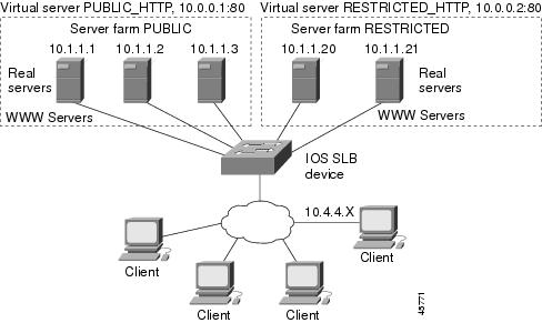
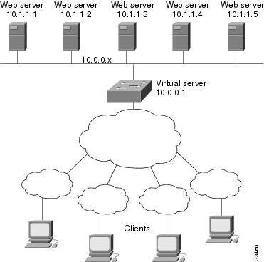
Figure 4-1 shows a sample IOS SLB network with the following components:
•![]() Two server farms—one configured to allow access by the public and named PUBLIC, one configured to allow limited access and named RESTRICTED.
Two server farms—one configured to allow access by the public and named PUBLIC, one configured to allow limited access and named RESTRICTED.
•![]() Five real servers configured as follows:
Five real servers configured as follows:
–![]() Three real servers in the PUBLIC server farm with IP addresses 10.1.1.1, 10.1.1.2, and 10.1.1.3
Three real servers in the PUBLIC server farm with IP addresses 10.1.1.1, 10.1.1.2, and 10.1.1.3
–![]() Two real servers in the restricted server farm with IP addresses 10.1.1.20 and 10.1.1.21
Two real servers in the restricted server farm with IP addresses 10.1.1.20 and 10.1.1.21
•![]() Two virtual servers—one configured to allow access by the public and named PUBLIC_HTTP and one configured to allow limited access and named RESTRICTED_HTTP.
Two virtual servers—one configured to allow access by the public and named PUBLIC_HTTP and one configured to allow limited access and named RESTRICTED_HTTP.
–![]() Virtual server PUBLIC_HTTP is configured with IP address 10.0.0.1 load balancing TCP connections on the WWW port (80).
Virtual server PUBLIC_HTTP is configured with IP address 10.0.0.1 load balancing TCP connections on the WWW port (80).
–![]() Virtual server RESTRICTED_HTTP is configured with IP address 10.0.0.2 load balancing TCP connections on the WWW port (80) and allows access only from clients from network 10.4.4.0 255.255.255.0.
Virtual server RESTRICTED_HTTP is configured with IP address 10.0.0.2 load balancing TCP connections on the WWW port (80) and allows access only from clients from network 10.4.4.0 255.255.255.0.
Figure 4-1 Example IOS SLB Network
The following sections include examples of the configuration commands used to configure and verify the IOS SLB network shown in Figure 4-1:
•![]() Restricted Client Configuration
Restricted Client Configuration
Server Farm Configuration
The following example shows the configuration for the server farm PUBLIC, associated with three real servers:
ip slb serverfarm PUBLIC
real 10.1.1.1
reassign 2
faildetect numconns 4 numclients 2
retry 20
inservice
exit
real 10.1.1.2
reassign 2
faildetect numconns 4
retry 20
inservice
exit
real 10.1.1.3
reassign 2
faildetect numconns 4
retry 20
inservice
end
The following example shows the configuration for the server farm RESTRICTED, associated with two real servers:
ip slb serverfarm RESTRICTED
real 10.1.1.20
reassign 2
faildetect numconns 4
retry 20
inservice
exit
real 10.1.1.21
reassign 2
faildetect numconns 4
retry 20
inservice
end
Virtual Server Configuration
The following example shows the configuration for the virtual servers PUBLIC_HTTP and RESTRICTED_HTTP:
ip slb vserver PUBLIC_HTTP
virtual 10.0.0.1 tcp www
serverfarm PUBLIC
idle 120
delay 5
inservice
exit
ip slb vserver RESTRICTED_HTTP
virtual 10.0.0.2 tcp www
serverfarm RESTRICTED
idle 120
delay 5
inservice
end
Restricted Client Configuration
The following example shows the configuration for the virtual server RESTRICTED_HTTP:
ip slb vserver RESTRICTED_HTTP
no inservice
client 10.4.4.0 255.255.255.0
inservice
end
Example: How to Configure a Complete IOS SLB Network
The following example provides a complete configuration using many of the commands described in this feature document:
ip slb probe PROBE2 http
request method POST url /probe.cgi?all
header HeaderName HeaderValue
!
ip slb serverfarm PUBLIC
nat server
real 10.1.1.1
reassign 4
faildetect numconns 16
retry 120
inservice
real 10.1.1.2
reassign 4
faildetect numconns 16
retry 120
inservice
probe PROBE2
!
ip slb serverfarm RESTRICTED
predictor leastconns
bindid 309
real 10.1.1.1
weight 32
maxconns 1000
reassign 4
faildetect numconns 16
retry 120
inservice
real 10.1.1.20
reassign 4
faildetect numconns 16
retry 120
inservice
real 10.1.1.21
reassign 4
faildetect numconns 16
retry 120
inservice
!
ip slb vserver PUBLIC_HTTP
virtual 10.0.0.1 tcp www
serverfarm PUBLIC
!
ip slb vserver RESTRICTED_HTTP
virtual 10.0.0.2 tcp www
serverfarm RESTRICTED
no advertise
sticky 60 group 1
idle 120
delay 5
client 10.4.4.0 255.255.255.0
synguard 3600000
inservice
Examples: How to Configure IOS SLB with Firewall Load Balancing
This section contains the following examples, illustrating several different IOS SLB firewall load-balancing configurations:
•![]() Example: How to Configure IOS SLB with Basic Firewall Load Balancing
Example: How to Configure IOS SLB with Basic Firewall Load Balancing
•![]() Example: How to Configure IOS SLB with Server Load Balancing and Firewall Load Balancing
Example: How to Configure IOS SLB with Server Load Balancing and Firewall Load Balancing
•![]() Example: How to Configure IOS SLB with Multiple Firewall Farms
Example: How to Configure IOS SLB with Multiple Firewall Farms
•![]() Example: How to Configure IOS SLB with Dual Firewall Load Balancing "Sandwich"
Example: How to Configure IOS SLB with Dual Firewall Load Balancing "Sandwich"
•![]() Example: How to Configure IOS SLB with RADIUS Load Balancing/Firewall Load Balancing "Sandwich"
Example: How to Configure IOS SLB with RADIUS Load Balancing/Firewall Load Balancing "Sandwich"
Example: How to Configure IOS SLB with Basic Firewall Load Balancing
Figure 4-2 shows a sample IOS SLB firewall load-balancing network with the following components:
•![]() Two firewalls with IP addresses as shown
Two firewalls with IP addresses as shown
•![]() An internal firewall load-balancing device on the secure side of the firewalls
An internal firewall load-balancing device on the secure side of the firewalls
•![]() An external firewall load-balancing device on the Internet side of the firewalls
An external firewall load-balancing device on the Internet side of the firewalls
•![]() One firewall farm named FIRE1, containing both firewalls
One firewall farm named FIRE1, containing both firewalls
Figure 4-2 IOS SLB with Layer 3 Firewalls in Different Subnets
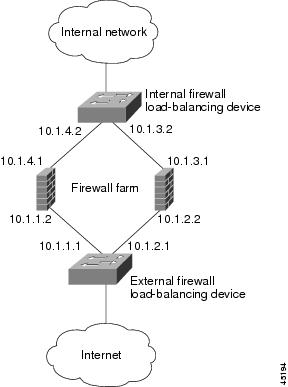
When you configure IOS SLB firewall load balancing, the load-balancing devices use route lookup to recognize flows destined for the firewalls. To enable route lookup, you must configure each device with the IP address of each firewall that will route flows to that device.
In the following firewall farm configuration samples:
•![]() The internal (secure side) firewall load-balancing device is configured with firewall IP addresses 10.1.3.1 and 10.1.4.1.
The internal (secure side) firewall load-balancing device is configured with firewall IP addresses 10.1.3.1 and 10.1.4.1.
•![]() The external (Internet side) firewall load-balancing device is configured with firewall IP addresses 10.1.1.2 and 10.1.2.2.
The external (Internet side) firewall load-balancing device is configured with firewall IP addresses 10.1.1.2 and 10.1.2.2.
Internal Firewall Load-Balancing Device
The following example shows the configuration for ping probe PROBE1, HTTP probe PROBE2, and firewall farm FIRE1, associated with the two real servers for the load-balancing device on the internal (secure) side of the firewall:
!-----Ping probe
ip slb probe PROBE1 ping
!-----IP address of other load-balancing device
address 10.1.1.1
faildetect 4
!-----HTTP probe
ip slb probe PROBE2 http
!-----IP address of other load-balancing device
address 10.1.2.1
expect status 401
!-----Firewall farm FIRE1
ip slb firewallfarm FIRE1
!-----First firewall
real 10.1.4.1
probe PROBE1
!-----Enable first firewall
inservice
!-----Second firewall
real 10.1.3.1
probe PROBE2
!-----Enable second firewall
inservice
External Firewall Load-Balancing Device
The following example shows the configuration for ping probe PROBE1, HTTP probe PROBE2, and firewall farm FIRE1, associated with the two real servers for the load-balancing device on the external (Internet) side of the firewall:
!-----Ping probe
ip slb probe PROBE1 ping
!-----IP address of other load-balancing device
address 10.1.4.2
faildetect 4
!-----HTTP probe
ip slb probe PROBE2 http
!-----IP address of other load-balancing device
address 10.1.3.2
expect status 401
!-----Firewall farm FIRE1
ip slb firewallfarm FIRE1
!-----First firewall
real 10.1.1.2
probe PROBE1
!-----Enable first firewall
inservice
!-----Second firewall
real 10.1.2.2
probe PROBE2
!-----Enable second firewall
inservice
exit
inservice
Example: How to Configure IOS SLB with Server Load Balancing and Firewall Load Balancing
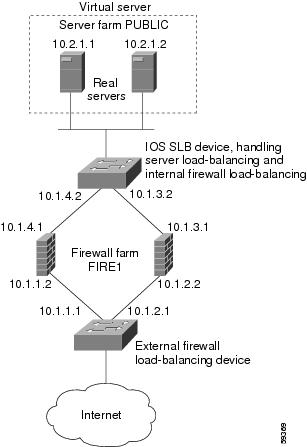
Figure 4-3 shows a sample IOS SLB load-balancing network with server load balancing and firewall load balancing running together, and the following components:
•![]() Two real servers with IP addresses as shown
Two real servers with IP addresses as shown
•![]() One server farm named PUBLIC, containing both real servers
One server farm named PUBLIC, containing both real servers
•![]() Two firewalls with IP addresses as shown
Two firewalls with IP addresses as shown
•![]() One firewall farm named FIRE1, containing both firewalls
One firewall farm named FIRE1, containing both firewalls
•![]() An internal IOS SLB device on the secure side of the firewalls, performing server load balancing and firewall load balancing
An internal IOS SLB device on the secure side of the firewalls, performing server load balancing and firewall load balancing
•![]() An external firewall load-balancing device on the Internet side of the firewalls
An external firewall load-balancing device on the Internet side of the firewalls
Figure 4-3 IOS SLB with Server Load Balancing and Firewall Load Balancing
In the following firewall farm configuration samples:
•![]() The internal (secure side) firewall load-balancing device is configured with firewall IP addresses 10.1.3.1 and 10.1.4.1.
The internal (secure side) firewall load-balancing device is configured with firewall IP addresses 10.1.3.1 and 10.1.4.1.
•![]() The external (Internet side) firewall load-balancing device is configured with firewall IP addresses 10.1.1.2 and 10.1.2.2.
The external (Internet side) firewall load-balancing device is configured with firewall IP addresses 10.1.1.2 and 10.1.2.2.
Internal Server and Firewall Load-Balancing Device
The following example shows the configuration for ping probes ABCPROBE and XYZPROBE, firewall farm FIRE1, and server farm PUBLIC for the load-balancing device on the internal (secure) side of the firewalls:
ip slb probe ABCPROBE ping
address 10.1.1.1
ip slb probe XYZPROBE ping
address 10.1.2.1
!
ip slb firewallfarm FIRE1
real 10.1.4.1
probe ABCPROBE
inservice
real 10.1.3.1
probe XYZPROBE
inservice
inservice
!
ip slb serverfarm PUBLIC
nat server
real 10.2.1.1
inservice
real 10.2.1.2
inservice
!
ip slb vserver HTTP1
virtual 128.1.0.1 tcp www
serverfarm PUBLIC
idle 120
delay 5
inservice
Note ![]() On Cisco Catalyst 6500 series switches, you can also specify that IOS SLB wildcard searches are to be performed by the route processor using the mls ip slb search wildcard rp command in global configuration mode.
On Cisco Catalyst 6500 series switches, you can also specify that IOS SLB wildcard searches are to be performed by the route processor using the mls ip slb search wildcard rp command in global configuration mode.
External Firewall Load-Balancing Device
The following example shows the configuration for ping probes ABCPROBE and XYZPROBE and firewall farm FIRE1 for the load-balancing device on the external (Internet) side of the firewalls:
ip slb probe ABCPROBE ping
address 10.1.4.2
ip slb probe XYZPROBE ping
address 10.1.3.2
ip slb firewallfarm FIRE1
real 10.1.1.2
probe ABCPROBE
inservice
probe XYZPROBE
inservice
Example: How to Configure IOS SLB with Multiple Firewall Farms
Figure 4-4 shows a sample IOS SLB load-balancing network with multiple firewall farms and the following components:
•![]() Four firewalls with IP addresses as shown
Four firewalls with IP addresses as shown
•![]() An internal firewall load-balancing device on the secure side of the firewalls
An internal firewall load-balancing device on the secure side of the firewalls
•![]() An external firewall load-balancing device on the Internet side of the firewalls
An external firewall load-balancing device on the Internet side of the firewalls
•![]() One firewall farm named ABCFARM, containing the two firewalls on the left.
One firewall farm named ABCFARM, containing the two firewalls on the left.
•![]() One firewall farm named XYZFARM, containing the two firewalls on the right.
One firewall farm named XYZFARM, containing the two firewalls on the right.
Figure 4-4 IOS SLB with Multiple Firewall Farms
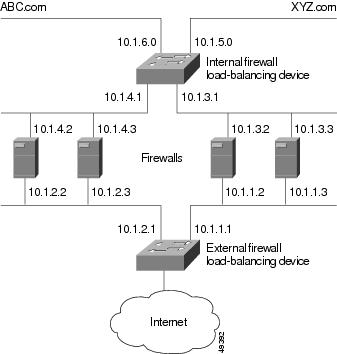
In the following firewall farm configuration samples:
•![]() The internal (secure side) firewall load-balancing device is configured with firewall IP addresses 10.1.3.1 and 10.1.4.1.
The internal (secure side) firewall load-balancing device is configured with firewall IP addresses 10.1.3.1 and 10.1.4.1.
•![]() The external (Internet side) firewall load-balancing device is configured with firewall IP addresses 10.1.1.2 and 10.1.2.2.
The external (Internet side) firewall load-balancing device is configured with firewall IP addresses 10.1.1.2 and 10.1.2.2.
Internal Firewall Load-Balancing Device
The following example shows the configuration for ping probes ABCPROBE and XYZPROBE and firewall farms ABCFARM and XYZFARM for the load-balancing device on the internal (secure) side of the firewalls:
ip slb probe ABCPROBE ping
address 10.1.2.1
ip slb probe XYZPROBE ping
address 10.1.1.1
ip slb firewallfarm ABCFARM
access source 10.1.6.0 255.255.255.0
inservice
real 10.1.4.2
probe ABCPROBE
inservice
real 10.1.4.3
probe ABCPROBE
inservice
ip slb firewallfarm XYZFARM
access source 10.1.5.0 255.255.255.0
inservice
real 10.1.3.2
probe XYZPROBE
inservice
real 10.1.3.3
probe XYZPROBE
inservice
External Firewall Load-Balancing Device
The following example shows the configuration for ping probes ABCPROBE and XYZPROBE and firewall farms ABCFARM and XYZFARM for the load-balancing device on the external (Internet) side of the firewalls:
ip slb probe ABCPROBE ping
address 10.1.4.1
ip slb probe XYZPROBE ping
address 10.1.3.1
ip slb firewallfarm ABCFARM
access destination 10.1.6.0 255.255.255.0
inservice
real 10.1.2.2
probe ABCPROBE
inservice
real 10.1.2.3
probe ABCPROBE
inservice
ip slb firewallfarm XYZFARM
access destination 10.1.5.0 255.255.255.0
inservice
real 10.1.1.2
probe XYZPROBE
inservice
real 10.1.1.3
probe XYZPROBE
inservice
Example: How to Configure IOS SLB with Dual Firewall Load Balancing "Sandwich"
Figure 4-5 illustrates a basic dual firewall load balancing "sandwich" configuration hosted on one IOS SLB device, including Virtual Private Network (VPN) routing and forwarding (VRF) and access interface configuration. VL105, VL106, VL107, and VL108 are VLANs.
Note ![]() The client and server in this configuration are directly connected; in a more typical deployment, additional routes would be needed inside and outside the VRF.
The client and server in this configuration are directly connected; in a more typical deployment, additional routes would be needed inside and outside the VRF.
Figure 4-5 IOS SLB with Dual Firewall Load Balancing "Sandwich"
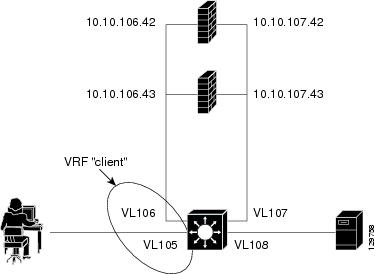
Following are the IOS SLB configuration statements for the configuration shown in Figure 4-5:
ip vrf client
rd 0:1
!
ip slb probe P642 ping
address 10.10.106.42
interval 120
ip slb probe P643 ping
address 10.10.106.43
interval 120
ip slb probe P742 ping
address 10.10.107.42
interval 120
ip slb probe P743 ping
address 10.10.107.43
interval 120
!
ip slb firewallfarm CLIENT
access inbound Vlan105
access outbound Vlan106
no inservice
!
real 10.10.106.42
probe P642
inservice
real 10.10.106.43
probe P643
inservice
protocol tcp
sticky 180 source
protocol datagram
sticky 180 source
predictor hash address port
!
ip slb firewallfarm SERVER
access inbound Vlan108
access outbound Vlan107
inservice
!
real 10.10.107.42
probe P742
inservice
real 10.10.107.43
probe P743
inservice
protocol tcp
sticky 180 destination
protocol datagram
sticky 180 destination
predictor hash address port
!
mls flow ip interface-full
!
!*************************************************
!* Switchports, port channels and trunks *
!* added to vlans 105-108 (left out for brevity) *
!*************************************************
!
interface Vlan105
ip vrf forwarding client
ip address 10.10.105.2 255.255.255.0
!
interface Vlan106
ip vrf forwarding client
ip address 10.10.106.2 255.255.255.0
!
interface Vlan107
ip address 10.10.107.2 255.255.255.0
!
interface Vlan108
ip address 10.10.108.2 255.255.255.0
!
ip route 10.10.105.0 255.255.255.0 10.10.107.42
ip route vrf client 10.10.108.0 255.255.255.0 10.10.106.42
Examples: How to Configure IOS SLB with Probes
This section contains the following examples, illustrating several different IOS SLB probe configurations:
•![]() Example: How to Configure IOS SLB with Ping and HTTP Probes
Example: How to Configure IOS SLB with Ping and HTTP Probes
•![]() Example: How to Configure IOS SLB with Routed Probe
Example: How to Configure IOS SLB with Routed Probe
Example: How to Configure IOS SLB with Ping and HTTP Probes
Figure 4-6 shows a sample configuration with IOS SLB real server connections configured as part of a server farm, focusing on using ping and HTTP probes to monitor applications that are server load-balanced.
Figure 4-6 Sample Ping and HTTP Probe Topology
:
The topology shown in Figure 4-6 is a heterogeneous server farm servicing one virtual server. Following are the configuration statements for this topology, including a ping probe named PROBE1 and an HTTP probe named PROBE2:
! Configure ping probe PROBE1, change CLI to IOS SLB probe configuration mode
ip slb probe PROBE1 ping
! Configure probe to receive responses from IP address 13.13.13.13
address 13.13.13.13
! Configure unacknowledged ping threshold to 16
faildetect 16
! Configure ping probe timer interval to send every 11 seconds
interval 11
! Configure HTTP probe PROBE2
ip slb probe PROBE2 http
! Configure request method as POST, set URL as /probe.cgi?all
request method post url /probe.cgi?all
! Configure header HeaderName
header HeaderName HeaderValue
! Configure basic authentication username and password
credentials Semisweet chips
! Exit to global configuration mode
exit
! Enter server farm configuration mode for server farm PUBLIC
ip slb serverfarm PUBLIC
! Configure NAT server and real servers on the server farm
nat server
real 10.1.1.1
inservice
real 10.1.1.2
inservice
real 10.1.1.3
inservice
real 10.1.1.4
inservice
real 10.1.1.5
inservice
! Configure ping probe on the server farm
probe PROBE1
! Configure HTTP probe on the server farm
probe PROBE2
end
Example: How to Configure IOS SLB with Routed Probe
Figure 4-7 shows a typical datacenter and IOS SLB configuration. Virtual server ACME_VSERVER is configured with two real servers (10.10.10.1 and 10.10.10.2) in server farm ACME_FARM. The user wants the real servers to fail based on the health of the backend server (10.10.10.3). To accomplish this configuration without sending health checks through the real servers, the user defines BACKEND, a routed ping probe to the backend server's IP address.
Figure 4-7 IOS SLB with a Routed Ping Probe
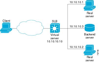
Following are the IOS SLB configuration statements for the configuration shown in Figure 4-7:
ip slb probe BACKEND ping
address 10.10.10.3 routed
ip slb serverfarm ACME_SFARM
nat server
probe BACKEND
real 10.10.10.1
inservice
real 10.10.10.2
inservice
ip slb vserver ACME_VSERVER
virtual 10.10.10.10 tcp 80
serverfarm ACME_SFARM
inservice
Example: How to Configure a Layer 3 Switch with IOS SLB
Figure 4-8 shows a sample configuration with IOS SLB server connections configured as part of a server farm.
Figure 4-8 Network Configuration for IOS SLB
As shown in the following sample configuration, the example topology has three public web servers and two restricted web servers for privileged clients in subnet 10.4.4.0. The public web servers are weighted according to their capacity, with server 10.1.1.2 having the lowest capacity and having a connection limit imposed on it. The restricted web servers are configured as members of the same sticky group, so that HTTP connections and Secure Socket Layer (SSL) connections from the same client use the same real server.
The network configuration to provide the previously described IOS SLB functionality follows:
ip slb probe PROBE2 http
request method POST url /probe.cgi?all
header HeaderName HeaderValue
header Authorization Basic U2VtaXN3ZWV0OmNoaXBz
!
ip slb serverfarm PUBLIC
nat server
predictor leastconns
! First real server
real 10.1.1.1
reassign 4
faildetect numconns 16
retry 120
inservice
! Second real server
real 10.1.1.2
reassign 4
faildetect numconns 16
retry 120
inservice
! Third real server
real 10.1.1.3
reassign 4
faildetect numconns 16
retry 120
inservice
! Probe
probe PROBE2
! Restricted web server farm
ip slb serverfarm RESTRICTED
predictor leastconns
! First real server
real 10.1.1.20
reassign 2
faildetect numconns 4
retry 20
inservice
! Second real server
real 10.1.1.21
reassign 2
faildetect numconns 4
retry 20
inservice
!
! Unrestricted web virtual server
ip slb vserver PUBLIC_HTTP
virtual 10.0.0.1 tcp www
serverfarm PUBLIC
idle 120
delay 5
inservice
!
! Restricted HTTP virtual server
ip slb vserver RESTRICTED_HTTP
virtual 10.0.0.1 tcp www
serverfarm RESTRICTED
client 10.4.4.0 255.255.255.0
sticky 60 group 1
idle 120
delay 5
inservice
!
! Restricted SSL virtual server
ip slb vserver RESTRICTED_SSL
virtual 10.0.0.1 tcp https
serverfarm RESTRICTED
client 10.4.4.0 255.255.255.0
sticky 60 group 1
idle 120
delay 5
inservice
!
interface GigabitEthernet1/1
switchport
switchport access vlan 3
switchport mode access
no ip address
!
interface FastEthernet2/1
switchport
switchport access vlan 2
switchport mode access
no ip address
!
interface FastEthernet2/2
switchport
switchport access vlan 2
switchport mode access
no ip address
!
interface FastEthernet2/3
switchport
switchport access vlan 2
switchport mode access
no ip address
!
interface Vlan2
ip address 10.1.1.100 255.255.255.0
!
interface Vlan3
ip address 40.40.40.1 255.255.255.0
Examples: How to Configure IOS SLB with NAT and Static NAT
This section contains the following examples, illustrating several different IOS SLB NAT configurations:
•![]() Example: How to Configure IOS SLB with NAT
Example: How to Configure IOS SLB with NAT
•![]() Example: How to Configure IOS SLB with Static NAT
Example: How to Configure IOS SLB with Static NAT
•![]() Example: How to Configure IOS SLB with GPRS Load Balancing and NAT
Example: How to Configure IOS SLB with GPRS Load Balancing and NAT
•![]() Example: How to Configure IOS SLB with GPRS Load Balancing, NAT, and GTP Cause Code Inspection
Example: How to Configure IOS SLB with GPRS Load Balancing, NAT, and GTP Cause Code Inspection
Example: How to Configure IOS SLB with NAT
Figure 4-9 shows a sample configuration with IOS SLB real server connections configured as part of a server farm, focusing on the configuration of the NAT server and address pool of clients.
Figure 4-9 Sample IOS SLB NAT Topology
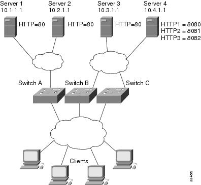
The topology in Figure 4-9 has four web servers, configured as follows:
•![]() Servers 1, 2, and 3 are running single HTTP server applications listening on port 80.
Servers 1, 2, and 3 are running single HTTP server applications listening on port 80.
•![]() Server 4 has multiple HTTP server applications listening on ports 8080, 8081, and 8082.
Server 4 has multiple HTTP server applications listening on ports 8080, 8081, and 8082.
Server 1 and Server 2 are load-balanced using Switch A, which is performing server address translation.
Server 3 and Server 4 are load-balanced using Switch B and Switch C. These two switches are performing both server and client address translation since there are multiple paths between the clients and the servers. These switches also must perform server port translation for HTTP packets to and from Server 4.
Switch A Configuration Statements
ip slb serverfarm FARM1
! Translate server addresses
nat server
! Server 1 port 80
real 10.1.1.1
reassign 2
faildetect numconns 4 numclients 2
retry 20
inservice
! Server 2 port 80
real 10.2.1.1
reassign 2
faildetect numconns 4
retry 20
inservice
!
ip slb vserver HTTP1
! Manage HTTP (port 80) requests
virtual 128.1.0.1 tcp www
serverfarm FARM1
idle 120
delay 5
inservice
Switch B Configuration Statements
ip slb natpool web-clients 128.3.0.1 128.3.0.254
! NAT address pool for clients
ip slb serverfarm FARM2
! Translate server addresses
nat server
! Translate client addresses
nat client web-clients
! Server 3 port 80
real 10.3.1.1
reassign 2
faildetect numconns 4
retry 20
inservice
! Server 4 port 8080
real 10.4.1.1 port 8080
reassign 2
faildetect numconns 4
retry 20
inservice
! Server 4 port 8081
real 10.4.1.1 port 8081
reassign 2
faildetect numconns 4
retry 20
inservice
! Server 4 port 8082
real 10.4.1.1 port 8082
reassign 2
faildetect numconns 4
retry 20
inservice
!
ip slb vserver HTTP2
! Manage HTTP (port 80) requests
virtual 128.2.0.1 tcp www
serverfarm FARM2
idle 120
delay 5
inservice
Switch C Configuration Statements
ip slb natpool web-clients 128.5.0.1 128.5.0.254
! NAT address pool for clients
ip slb serverfarm FARM2
! Translate server addresses
nat server
! Translate client addresses
nat client web-clients
! Server 3 port 80
real 10.3.1.1
reassign 2
faildetect numconns 4
retry 20
inservice
! Server 4 port 8080
real 10.4.1.1 port 8080
reassign 2
faildetect numconns 4
retry 20
inservice
! Server 4 port 8081
real 10.4.1.1 port 8081
reassign 2
faildetect numconns 4
retry 20
inservice
! Server 4 port 8082
real 10.4.1.1 port 8082
reassign 2
faildetect numconns 4
retry 20
inservice
!
ip slb vserver HTTP2
! Manage HTTP (port 80) requests
virtual 128.4.0.1 tcp www
serverfarm FARM2
idle 120
delay 5
inservice
Example: How to Configure IOS SLB with Static NAT
The following example shows configuration statements for the following items:
•![]() A DNS probe, PROBE4, configured to supply real server IP address 13.13.13.13 in response to domain name resolve requests.
A DNS probe, PROBE4, configured to supply real server IP address 13.13.13.13 in response to domain name resolve requests.
•![]() A server farm, DNS, that is configured to use server NAT and PROBE4.
A server farm, DNS, that is configured to use server NAT and PROBE4.
•![]() An all-port virtual server, 10.11.11.11, associated with server farm DNS, that performs per-packet server load balancing for UDP connections.
An all-port virtual server, 10.11.11.11, associated with server farm DNS, that performs per-packet server load balancing for UDP connections.
•![]() A real server, 10.1.1.3, associated with server farm DNS, configured for static NAT and per-packet server load balancing.
A real server, 10.1.1.3, associated with server farm DNS, configured for static NAT and per-packet server load balancing.
ip slb probe PROBE4 dns
lookup 13.13.13.13
!
ip slb serverfarm DNS
nat server
probe PROBE4
real 10.1.1.3
inservice
!
ip slb vserver DNS
virtual 10.11.11.11 UDP 0 service per-packet
serverfarm DNS
!
ip slb static nat 10.11.11.11 per-packet
real 10.1.1.3
Examples: How to Configure IOS SLB with Redundancy
This section contains the following examples, illustrating several different IOS SLB configurations with redundancy:
•![]() Examples: How to Configure IOS SLB with Stateless Backup
Examples: How to Configure IOS SLB with Stateless Backup
•![]() Example: How to Configure IOS SLB with Stateful Backup
Example: How to Configure IOS SLB with Stateful Backup
•![]() Example: How to Configure IOS SLB with Stateful Backup of Redundant Route Processors
Example: How to Configure IOS SLB with Stateful Backup of Redundant Route Processors
•![]() Example: How to Configure IOS SLB with Active Standby
Example: How to Configure IOS SLB with Active Standby
Examples: How to Configure IOS SLB with Stateless Backup
There are several different ways in which you can configure IOS SLB stateless backup. The differences between the configurations depend on the networking capabilities of your load balancing devices, and on the capabilities of the distribution devices that direct client traffic to those load balancing devices.
•![]() If a load balancing device is capable of Layer 2 switching and VLAN trunking (such as the Cisco Catalyst 6500 series switch), you can wire the device directly to its real servers, and it can manage outbound flows from the real servers while acting as a standby for IOS SLB. HSRP is used on the server-side VLANs of the load balancing device, with the real servers routing to the HSRP address.
If a load balancing device is capable of Layer 2 switching and VLAN trunking (such as the Cisco Catalyst 6500 series switch), you can wire the device directly to its real servers, and it can manage outbound flows from the real servers while acting as a standby for IOS SLB. HSRP is used on the server-side VLANs of the load balancing device, with the real servers routing to the HSRP address.
•![]() If a load balancing device is not capable of both Layer 2 switching and VLAN trunking, you must connect it and its real servers to a Layer 2 switch. This configuration is required in order to use HSRP on the server-side VLANs.
If a load balancing device is not capable of both Layer 2 switching and VLAN trunking, you must connect it and its real servers to a Layer 2 switch. This configuration is required in order to use HSRP on the server-side VLANs.
•![]() If a distribution device is capable of Layer 3 switching, it can use route redistribution to direct flows to the active load balancing device.
If a distribution device is capable of Layer 3 switching, it can use route redistribution to direct flows to the active load balancing device.
•![]() If a distribution device is capable of Layer 2 switching, it can use client-side HSRP on the load balancing device to direct flows to the active load balancing device.
If a distribution device is capable of Layer 2 switching, it can use client-side HSRP on the load balancing device to direct flows to the active load balancing device.
•![]() While HSRP offers faster failover times, routing converges quickly enough for most configurations. If you use both client-side and server-side HSRP on the load balancing devices, you must use HSRP interface tracking and priorities to synchronize the client-side and server-side HSRP groups.
While HSRP offers faster failover times, routing converges quickly enough for most configurations. If you use both client-side and server-side HSRP on the load balancing devices, you must use HSRP interface tracking and priorities to synchronize the client-side and server-side HSRP groups.
This section contains the following examples, illustrating several different IOS SLB stateless backup configurations:
•![]() Example: How to Configure Dynamic Routing and Trunking
Example: How to Configure Dynamic Routing and Trunking
•![]() Example: How to Configure Dynamic Routing and No Trunking
Example: How to Configure Dynamic Routing and No Trunking
•![]() Example: How to Configure Static Routing and Trunking
Example: How to Configure Static Routing and Trunking
•![]() Example: How to Configure Static Routing and No Trunking
Example: How to Configure Static Routing and No Trunking
Note ![]() Stateful backup is omitted from these examples in the interest of simplicity. To see an example that uses stateful backup, see the "Example: How to Configure IOS SLB with Stateful Backup" section.
Stateful backup is omitted from these examples in the interest of simplicity. To see an example that uses stateful backup, see the "Example: How to Configure IOS SLB with Stateful Backup" section.
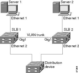
Example: How to Configure Dynamic Routing and Trunking
Figure 4-10 shows a sample IOS SLB stateless backup configuration with the following characteristics:
•![]() The IP address for real server 1 is 10.10.1.3, and for real server 2 is 10.10.1.4, routed to clients through 10.10.1.100.
The IP address for real server 1 is 10.10.1.3, and for real server 2 is 10.10.1.4, routed to clients through 10.10.1.100.
•![]() The IP address for the virtual server is 10.10.14.1.
The IP address for the virtual server is 10.10.14.1.
•![]() The IP address for VLAN 1 is 10.10.1.0, with a subnet mask of 255.255.255.0.
The IP address for VLAN 1 is 10.10.1.0, with a subnet mask of 255.255.255.0.
•![]() The IP address for Subnet 2 is 10.10.2.0, with a subnet mask of 255.255.255.0.
The IP address for Subnet 2 is 10.10.2.0, with a subnet mask of 255.255.255.0.
•![]() The IP address for Subnet 3 is 10.10.3.0, with a subnet mask of 255.255.255.0.
The IP address for Subnet 3 is 10.10.3.0, with a subnet mask of 255.255.255.0.
•![]() The distribution device uses EIGRP to learn the route to 10.10.14.1 through either 10.10.2.1 or 10.10.3.1, depending on which IOS SLB is active.
The distribution device uses EIGRP to learn the route to 10.10.14.1 through either 10.10.2.1 or 10.10.3.1, depending on which IOS SLB is active.
Figure 4-10 Stateless Backup with Layer 3 and Trunking
SLB 1 Configuration Statements
ip slb serverfarm SF1
real 10.10.1.3
reassign 2
faildetect numconns 4 numclients 2
retry 20
inservice
real 10.10.1.4
reassign 2
faildetect numconns 4
retry 20
inservice
ip slb vserver VS1
virtual 10.10.14.1 tcp www
serverfarm SF1
idle 120
delay 5
inservice standby SERVER
!
interface Ethernet1
switchport
switchport vlan 1
interface Ethernet2
ip address 10.10.2.1 255.255.255.0
interface vlan 1
ip address 10.10.1.1 255.255.255.0
standby ip 10.10.1.100
standby priority 10 preempt delay sync 20
standby name SERVER
standby track Ethernet2
standby timers 1 3
router eigrp 666
redistribute static
network 10.0.0.0
SLB 2 Configuration Statements
ip slb serverfarm SF1
real 10.10.1.3
reassign 2
faildetect numconns 4
retry 20
inservice
real 10.10.1.4
reassign 2
faildetect numconns 4
retry 20
inservice
ip slb vserver VS1
virtual 10.10.14.1 tcp www
serverfarm SF1
idle 120
delay 5
inservice standby SERVER
!
interface GigabitEthernet1
no ip address
switchport
switchport trunk encapsulation isl
interface Ethernet1
switchport
switchport vlan 1
interface Ethernet2
ip address 10.10.3.1 255.255.255.0
interface vlan 1
ip address 10.10.1.2 255.255.255.0
standby ip 10.10.1.100
standby priority 5 preempt delay sync 20
standby name SERVER
standby track Ethernet2
standby timers 1 3
router eigrp 666
redistribute static
network 10.0.0.0
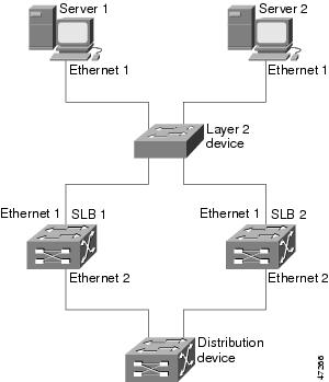
Example: How to Configure Dynamic Routing and No Trunking
Figure 4-11 shows a sample IOS SLB stateless backup configuration with the following characteristics:
•![]() The IP address for real server 1 is 10.10.1.3, and for real server 2 is 10.10.1.4, routed to clients through 10.10.1.100.
The IP address for real server 1 is 10.10.1.3, and for real server 2 is 10.10.1.4, routed to clients through 10.10.1.100.
•![]() The IP address for the virtual server is 10.10.14.1.
The IP address for the virtual server is 10.10.14.1.
•![]() The IP address for Subnet 2 is 10.10.2.0, with a subnet mask of 255.255.255.0.
The IP address for Subnet 2 is 10.10.2.0, with a subnet mask of 255.255.255.0.
•![]() The IP address for Subnet 3 is 10.10.3.0, with a subnet mask of 255.255.255.0.
The IP address for Subnet 3 is 10.10.3.0, with a subnet mask of 255.255.255.0.
•![]() The distribution device uses EIGRP to learn the route to 10.10.14.1 through either 10.10.2.2 or 10.10.3.2, depending on which IOS SLB is active.
The distribution device uses EIGRP to learn the route to 10.10.14.1 through either 10.10.2.2 or 10.10.3.2, depending on which IOS SLB is active.
Figure 4-11 Stateless Backup with Layer 3 and No Trunking
SLB 1 Configuration Statements
ip slb serverfarm SF1
real 10.10.1.3
reassign 2
faildetect numconns 4
retry 20
inservice
real 10.10.1.4
reassign 2
faildetect numconns 4
retry 20
inservice
ip slb vserver VS1
virtual 10.10.14.1 tcp www
serverfarm SF1
idle 120
delay 5
inservice standby SERVER
!
interface Ethernet1
ip address 10.10.1.1 255.255.255.0
standby ip 10.10.1.100
standby priority 10 preempt delay sync 20
standby name SERVER
standby track Ethernet2
standby timers 1 3
interface Ethernet2
ip address 10.10.2.1 255.255.255.0
router eigrp 666
redistribute static
network 10.0.0.0
SLB 2 Configuration Statements
ip slb serverfarm SF1
real 10.10.1.3
reassign 2
faildetect numconns 4
retry 20
inservice
real 10.10.1.4
reassign 2
faildetect numconns 4
retry 20
inservice
ip slb vserver VS1
virtual 10.10.14.1 tcp www
serverfarm SF1
idle 120
delay 5
inservice standby SERVER
!
interface Ethernet1
ip address 10.10.1.2 255.255.255.0
standby ip 10.10.1.100
standby priority 5 preempt delay sync 20
standby name SERVER
standby track Ethernet2
standby timers 1 3
interface Ethernet2
ip address 10.10.3.1 255.255.255.0
router eigrp 666
redistribute static
network 10.0.0.0
Example: How to Configure Static Routing and Trunking
Figure 4-12 shows a sample IOS SLB stateless backup configuration with the following characteristics:
•![]() The IP address for real server 1 is 10.10.1.3, and for real server 2 is 10.10.1.4, routed to clients through 10.10.1.100.
The IP address for real server 1 is 10.10.1.3, and for real server 2 is 10.10.1.4, routed to clients through 10.10.1.100.
•![]() The IP address for the virtual server is 10.10.14.1.
The IP address for the virtual server is 10.10.14.1.
•![]() The IP address for VLAN 1 is 10.10.1.0, with a subnet mask of 255.255.255.0.
The IP address for VLAN 1 is 10.10.1.0, with a subnet mask of 255.255.255.0.
•![]() The IP address for Subnet 2 is 10.10.2.0, with a subnet mask of 255.255.255.0.
The IP address for Subnet 2 is 10.10.2.0, with a subnet mask of 255.255.255.0.
•![]() The IP address for Subnet 3 is 10.10.3.0, with a subnet mask of 255.255.255.0.
The IP address for Subnet 3 is 10.10.3.0, with a subnet mask of 255.255.255.0.
•![]() The configuration uses static routing to the HSRP route on the distribution device.
The configuration uses static routing to the HSRP route on the distribution device.
Figure 4-12 Stateless Backup with Layer 2 and Trunking
SLB 1 Configuration Statements
ip slb serverfarm SF1
real 10.10.1.3
reassign 2
faildetect numconns 4
retry 20
inservice
real 10.10.1.4
reassign 2
faildetect numconns 4
retry 20
inservice
ip slb vserver VS1
virtual 10.10.14.1 tcp www
serverfarm SF1
idle 120
delay 5
inservice standby SERVER
!
interface Ethernet1
switchport
switchport vlan 1
interface Ethernet2
ip address 10.10.2.1 255.255.255.0
standby ip 10.10.2.100
standby priority 10 preempt delay sync 20
standby track vlan1
standby timers 1 3
interface vlan 1
ip address 10.10.1.1 255.255.255.0
standby ip 10.10.1.100
standby priority 10 preempt delay sync 20
standby name SERVER
standby track Ethernet2
standby timers 1 3
SLB 2 Configuration Statements
ip slb serverfarm SF1
real 10.10.1.3
reassign 2
faildetect numconns 4
retry 20
inservice
real 10.10.1.4
reassign 2
faildetect numconns 4
retry 20
inservice
ip slb vserver VS1
virtual 10.10.14.1 tcp www
serverfarm SF1
idle 120
delay 5
inservice standby SERVER
!
interface GigabitEthernet1
no ip address
switchport
switchport trunk encapsulation isl
interface Ethernet1
switchport
switchport vlan 1
interface Ethernet2
ip address 10.10.2.2 255.255.255.0
standby ip 10.10.2.100
standby priority 5 preempt delay sync 20
standby track vlan 1
standby timers 1 3
interface vlan 1
ip address 10.10.1.2 255.255.255.0
standby ip 10.10.1.100
standby priority 5 preempt delay sync 20
standby name SERVER
standby track Ethernet2
standby timers 1 3
Distribution Device Configuration Statements
interface Ethernet1
switchport
switchport distribution vlan 2
interface Ethernet2
switchport
switchport distribution vlan 2
interface vlan2
ip address 10.10.2.3 255.255.255.0
no shut
ip route 10.10.14.1 255.255.255.255 10.10.2.100
Example: How to Configure Static Routing and No Trunking
Figure 4-13 shows a sample IOS SLB stateless backup configuration with the following characteristics:
•![]() The IP address for real server 1 is 10.10.1.3, and for real server 2 is 10.10.1.4, routed to clients through 10.10.1.100.
The IP address for real server 1 is 10.10.1.3, and for real server 2 is 10.10.1.4, routed to clients through 10.10.1.100.
•![]() The IP address for the virtual server is 10.10.14.1.
The IP address for the virtual server is 10.10.14.1.
•![]() The IP address for Subnet 2 is 10.10.2.0, with a subnet mask of 255.255.255.0.
The IP address for Subnet 2 is 10.10.2.0, with a subnet mask of 255.255.255.0.
•![]() The IP address for Subnet 3 is 10.10.3.0, with a subnet mask of 255.255.255.0.
The IP address for Subnet 3 is 10.10.3.0, with a subnet mask of 255.255.255.0.
•![]() The configuration uses static routing to the HSRP route on the distribution device.
The configuration uses static routing to the HSRP route on the distribution device.
Figure 4-13 Stateless Backup with Layer 2 and No Trunking
SLB 1 Configuration Statements
ip slb serverfarm SF1
real 10.10.1.3
reassign 2
faildetect numconns 4
retry 20
inservice
real 10.10.1.4
reassign 2
faildetect numconns 4
retry 20
inservice
ip slb vserver VS1
virtual 10.10.14.1 tcp www
serverfarm SF1
idle 120
delay 5
inservice standby SERVER
!
interface Ethernet1
ip address 10.10.1.1 255.255.255.0
standby ip 10.10.1.100
standby priority 10 preempt delay sync 20
standby name SERVER
standby track Ethernet2
standby timers 1 3
interface Ethernet2
ip address 10.10.2.1 255.255.255.0
standby ip 10.10.2.100
standby priority 10 preempt delay sync 20
standby track Ethernet1
standby timers 1 3
SLB 2 Configuration Statements
ip slb serverfarm SF1
real 10.10.1.3
reassign 2
faildetect numconns 4
retry 20
inservice
real 10.10.1.4
reassign 2
faildetect numconns 4
retry 20
inservice
ip slb vserver VS1
virtual 10.10.14.1 tcp www
serverfarm SF1
idle 120
delay 5
inservice standby SERVER
!
interface Ethernet1
ip address 10.10.1.2 255.255.255.0
standby ip 10.10.1.100
standby priority 5 preempt delay sync 20
standby name SERVER
standby track Ethernet2
standby timers 1 3
!
interface Ethernet2
ip address 10.10.2.2 255.255.255.0
standby ip 10.10.2.100
standby priority 5 preempt delay sync 20
standby track Ethernet1
standby timers 1 3
Distribution Device Configuration Statements
interface Ethernet1
switchport
switchport distribution vlan 2
interface Ethernet2
switchport
switchport distribution vlan 2
interface vlan2
ip address 10.10.2.3 255.255.255.0
no shut
ip route 10.10.14.1 255.255.255.255 10.10.2.100
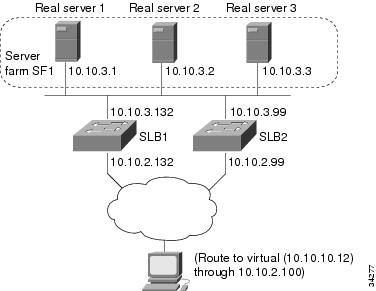
Example: How to Configure IOS SLB with Stateful Backup
This sample configuration focuses on the IOS SLB real server connections configured as part of a server farm, with real and virtual servers over Fast Ethernet interfaces configured with stateful backup standby connections.
Figure 4-14 is an example of a stateful backup configuration, using HSRP on both the client and server sides to manage failover. The real servers route outbound flows to 10.10.3.100, which is the HSRP address on the server side interfaces. The client (or access router), routes to the virtual IP address (10.10.10.12) through 10.10.2.100, HSRP address on the client side.
Notice the loopback interfaces configured on both devices for the exchange of these messages. Each IOS SLB should also be given duplicate routes to the other switch loopback address. This configuration allows replication messages to flow despite an interface failure.
Note ![]() To allow HSRP to function properly, the set spantree portfast command must be configured on any Layer 2 device between the IOS SLB switches.
To allow HSRP to function properly, the set spantree portfast command must be configured on any Layer 2 device between the IOS SLB switches.
Figure 4-14 IOS SLB Stateful Environment
Switch SLB1 Configuration Statements
ip slb serverfarm SF1
nat server
real 10.10.3.1
inservice
real 10.10.3.2
inservice
real 10.10.3.3
inservice
!
ip slb vserver VS1
virtual 10.10.10.12 tcp telnet
serverfarm SF1
replicate casa 10.10.99.132 10.10.99.99 1024 password PASS
inservice standby virt
!
interface loopback 1
ip address 10.10.99.132 255.255.255.255
!
interface FastEthernet1
ip address 10.10.3.132 255.255.255.0
no ip redirects
no ip mroute-cache
standby priority 5 preempt
standby name out
standby ip 10.10.3.100
standby track FastEthernet2
standby timers 1 3
interface FastEthernet2
ip address 10.10.2.132 255.255.255.0
no ip redirects
standby priority 5
standby name virt
standby ip 10.10.2.100
standby timers 1 3
Switch SLB2 Configuration Statements
ip slb serverfarm SF1
nat server
real 10.10.3.1
inservice
real 10.10.3.2
inservice
real 10.10.3.3
inservice
!
ip slb vserver VS1
virtual 10.10.10.12 tcp telnet
serverfarm SF1
replicate casa 10.10.99.99 10.10.99.132 1024 password PASS
inservice standby virt
!
interface loopback 1
ip address 10.10.99.99 255.255.255.255
!
interface FastEthernet2
ip address 10.10.2.99 255.255.255.0
no ip redirects
no ip route-cache
no ip mroute-cache
standby priority 10 preempt delay sync 20
standby name virt
standby ip 10.10.2.100
standby track FastEthernet3
standby timers 1 3
!
interface FastEthernet3
ip address 10.10.3.99 255.255.255.0
no ip redirects
no ip route-cache
no ip mroute-cache
standby priority 10 preempt delay 20
standby name out
standby ip 10.10.3.100
standby track FastEthernet2
standby timers 1 3
Example: How to Configure IOS SLB with Stateful Backup of Redundant Route Processors
In Figure 4-15, the IOS SLB device includes two Supervisor engines configured for stateful backup. If the active Supervisor engine fails, the backup Supervisor engine takes over through RPR+ with IOS SLB synchronization information already populated. IOS SLB replicates state information for virtual server ACME_VSERVER (10.10.10.10) from the active Supervisor engine to the backup every 20 seconds. The real servers (10.10.10.1, 10.10.10.2, and 10.10.10.3) are configured in server farm ACME_SFARM.
Figure 4-15 IOS SLB with Redundant Route Processors
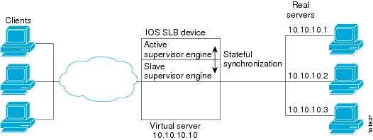
Following are the IOS SLB configuration statements for the configuration shown in Figure 4-15:
ip slb replicate slave rate 300
ip slb serverfarm ACME_SFARM
nat server
real 10.10.10.1
inservice
real 10.10.10.2
inservice
real 10.10.10.3
inservice
ip slb vserver ACME_VSERVER
virtual 10.10.10.10 tcp 80
replicate interval 20
replicate slave
serverfarm ACME_SFARM
inservice
Example: How to Configure IOS SLB with Active Standby
Figure 4-16 shows an IOS SLB network configured for active standby, with two IOS SLB devices load-balancing the same virtual IP address while backing up each other. If either device fails, the other takes over its load through normal HSRP failover and IOS SLB stateless redundancy.
Figure 4-16 IOS SLB Active Standby
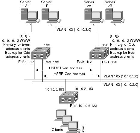
The sample network configuration in Figure 4-16 has the following characteristics:
•![]() SLB 1 balances servers 1A and 1B and SLB 2 balances 2A and 2B.
SLB 1 balances servers 1A and 1B and SLB 2 balances 2A and 2B.
•![]() One virtual IP address (10.10.10.12 for web) is supported across the two IOS SLB devices.
One virtual IP address (10.10.10.12 for web) is supported across the two IOS SLB devices.
•![]() Client traffic is divided in an access router, sending clients with even IP addresses to HSRP1 (10.10.5.100) and clients with odd IP addresses to HSRP2 (10.10.2.100). SLB 1 is configured as primary for clients with odd IP addresses, and SLB 2 is primary for clients with even IP addresses.
Client traffic is divided in an access router, sending clients with even IP addresses to HSRP1 (10.10.5.100) and clients with odd IP addresses to HSRP2 (10.10.2.100). SLB 1 is configured as primary for clients with odd IP addresses, and SLB 2 is primary for clients with even IP addresses.
•![]() The IOS SLB devices balance the traffic to disjoint sets of real servers. (If client NAT was used in this example, this characteristic would not be a requirement).
The IOS SLB devices balance the traffic to disjoint sets of real servers. (If client NAT was used in this example, this characteristic would not be a requirement).
•![]() Each set of real servers has a default gateway configured to its IOS SLB device.
Each set of real servers has a default gateway configured to its IOS SLB device.
•![]() The HSRP address on VLAN 105 is 10.10.5.100. The HSRP address on VLAN 102 is 10.10.2.100.
The HSRP address on VLAN 105 is 10.10.5.100. The HSRP address on VLAN 102 is 10.10.2.100.
SLB 1 Configuration Statements
ip slb serverfarm EVEN
nat server
real 10.10.3.2
reassign 2
faildetect numconns 4 numclients 2
retry 20
inservice
real 10.10.3.3
reassign 2
faildetect numconns 4
retry 20
inservice
!
ip slb serverfarm ODD
nat server
real 10.10.3.2
reassign 2
faildetect numconns 4
retry 20
inservice
real 10.10.3.3
reassign 2
faildetect numconns 4
retry 20
inservice
!-----Same EVEN virtual server as in SLB 2
ip slb vserver EVEN
virtual 10.10.10.12 tcp www
serverfarm EVEN
client 0.0.0.0 0.0.0.1
idle 120
delay 5
!-----See standby name in Ethernet 3/3 below
inservice standby STANDBY_EVEN
!-----Same ODD virtual server as in SLB 2
ip slb vserver ODD
virtual 10.10.10.12 tcp www
serverfarm ODD
client 0.0.0.1 0.0.0.1
idle 120
delay 5
!-----See standby name in Ethernet 3/2 below
inservice standby STANDBY_ODD
!
interface Ethernet3/2
ip address 10.10.5.132 255.255.255.0
standby priority 20 preempt delay sync 20
!-----See standby name in SLB 2, Ethernet 3/5
standby name STANDBY_ODD
standby ip 10.10.5.100
standby track Ethernet3/3
standby timers 1 3
!
interface Ethernet3/3
ip address 10.10.2.132 255.255.255.0
standby priority 10
!-----See standby name in SLB 2, Ethernet 3/1
standby name STANDBY_EVEN
standby ip 10.10.2.100
standby track Ethernet3/2
standby timers 1 3
SLB 2 Configuration Statements
ip slb serverfarm EVEN
nat server
real 10.10.3.4
reassign 2
faildetect numconns 4
retry 20
inservice
real 10.10.3.5
reassign 2
faildetect numconns 4
retry 20
inservice
!
ip slb serverfarm ODD
nat server
real 10.10.3.4
reassign 2
faildetect numconns 4
retry 20
inservice
real 10.10.3.5
reassign 2
faildetect numconns 4
retry 20
inservice
!-----Same EVEN virtual server as in SLB 1
ip slb vserver EVEN
virtual 10.10.10.12 tcp www
serverfarm EVEN
client 0.0.0.0 0.0.0.1
idle 120
delay 5
!-----See standby name in Ethernet 3/1 below
inservice standby STANDBY_EVEN
!-----Same ODD virtual server as in SLB 1
ip slb vserver ODD
virtual 10.10.10.12 tcp www
serverfarm ODD
client 0.0.0.1 0.0.0.1
idle 120
delay 5
!-----See standby name in Ethernet 3/5 below
inservice standby STANDBY_ODD
!
interface Ethernet3/1
ip address 10.10.2.128 255.255.255.0
standby priority 20 preempt delay sync 20
!-----See standby name in SLB 1, Ethernet 3/3
standby name STANDBY_EVEN
standby ip 10.10.2.100
standby track Ethernet3/5
standby timers 1 3
!
interface Ethernet3/5
ip address 10.10.5.128 255.255.255.0
standby priority 10 preempt delay sync 20
!-----See standby name in SLB 1, Ethernet 3/2
standby name STANDBY_ODD
standby ip 10.10.5.100
standby track Ethernet3/1
standby timers 1 3
Access Router Configuration Statements
interface Ethernet0/0
ip address 10.10.5.183 255.255.255.0
no ip directed-broadcast
no ip route-cache
no ip mroute-cache
!
interface Ethernet0/1
ip address 10.10.2.183 255.255.255.0
no ip directed-broadcast
no ip route-cache
no ip mroute-cache
!
interface Ethernet0/2
ip address 10.10.6.183 255.255.255.0
no ip directed-broadcast
no ip route-cache
no ip mroute-cache
ip policy route-map virts
!
access-list 100 permit ip 0.0.0.1 255.255.255.254 host 10.10.10.12
access-list 101 permit ip 0.0.0.0 255.255.255.254 host 10.10.10.12
route-map virts permit 10
match ip address 100
set ip next-hop 10.10.5.100
!
route-map virts permit 15
match ip address 101
set ip next-hop 10.10.2.100
Example: How to Configure IOS SLB with Redistribution of Static Routes
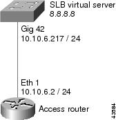
Figure 4-17 shows an IOS SLB network configured to distribute static routes to a virtual server's IP address. The route to the address is added to the routing table as static if you advertise the address when you bring the virtual server into service (using the inservice command). See the description of the advertise command in the Cisco IOS IP Application Services Command Reference for more details about advertising virtual server IP addresses.
Because the routing configuration varies from protocol to protocol, sample configurations for several different routing protocols are given.
Figure 4-17 IOS SLB Redistribution of Static Routes
Routing Information Protocol (RIP)
Following is the RIP static route redistribution configuration for the IOS SLB switch shown in Figure 4-17:
router rip
redistribute static
network 10.0.0.0
network 8.0.0.0
Following is the RIP static route redistribution configuration for the access router that is listening for routing updates shown in Figure 4-17:
router rip
network 10.0.0.0
network 8.0.0.0
Open Shortest Path First (OSPF)
Following is the OSPF static route redistribution configuration for the IOS SLB switch shown in Figure 4-17:
router ospf 1
redistribute static subnets
network 10.10.6.217 0.0.0.0 area 0
network 8.8.8.0 0.0.0.255 area 0
Following is the OSPF static route redistribution configuration for the access router that is listening for routing updates shown in Figure 4-17:
router ospf 1
network 10.10.6.2 0.0.0.0 area 0
network 8.8.8.0 0.0.0.255 area 0
Interior Gateway Routing Protocol (IGRP)
Following is the IGRP static route redistribution configuration for the IOS SLB switch shown in Figure 4-17:
router igrp 1
redistribute connected
redistribute static
network 8.0.0.0
network 10.0.0.0
Following is the IGRP static route redistribution configuration for the access router that is listening for routing updates shown in Figure 4-17:
router igrp 1
network 8.0.0.0
network 10.0.0.0
Enhanced Interior Gateway Routing Protocol (Enhanced IGRP)
Following is the Enhanced IGRP static route redistribution configuration for the IOS SLB switch shown in Figure 4-17:
router eigrp 666
redistribute static
network 10.0.0.0
network 8.0.0.0
Following is the Enhanced IGRP static route redistribution configuration for the access router that is listening for routing updates shown in Figure 4-17:
router eigrp 666
network 10.0.0.0
network 8.0.0.0
Example: How to Configure IOS SLB with WAP and UDP Load Balancing
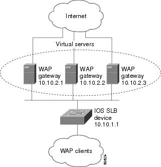
Figure 4-18 shows an IOS SLB network configured to balance WAP flows. In this example:
•![]() WAP flows are balanced between WAP gateways 10.10.2.1, 10.10.2.2, and 10.10.2.3.
WAP flows are balanced between WAP gateways 10.10.2.1, 10.10.2.2, and 10.10.2.3.
•![]() The clients connect to 10.10.1.1, the IOS SLB virtual server address.
The clients connect to 10.10.1.1, the IOS SLB virtual server address.
•![]() For a given session, load-balancing decisions change if the connection idles longer than the virtual server's idle connection timer (3000 seconds in this example).
For a given session, load-balancing decisions change if the connection idles longer than the virtual server's idle connection timer (3000 seconds in this example).
Figure 4-18 IOS SLB with WAP Load Balancing
There are two ways to configure IOS SLB load balancing for WAP:
•![]() To load-balance sessions running in connection-oriented WSP mode, define a WSP probe and use WAP load balancing. WAP load balancing requires a WAP virtual server configured on one of the WAP ports.
To load-balance sessions running in connection-oriented WSP mode, define a WSP probe and use WAP load balancing. WAP load balancing requires a WAP virtual server configured on one of the WAP ports.
•![]() To load-balance sessions running in connectionless WSP, connectionless secure WSP, and connection-oriented secure WSP modes, define a ping or WSP probe and use standard UDP load balancing with a low idle timer.
To load-balance sessions running in connectionless WSP, connectionless secure WSP, and connection-oriented secure WSP modes, define a ping or WSP probe and use standard UDP load balancing with a low idle timer.
Example: How to Balance WAP Flows on UDP Port 9201
The following example shows the configuration for the IOS SLB device shown in Figure 4-18, which balances WAP flows on UDP port 9201 (WSP/WTP/UDP):
ip slb probe PROBE3 wsp
url http://localhost/test.txt
!
ip slb serverfarm WAPFARM
nat server
real 10.10.2.1
inservice
real 10.10.2.2
inservice
real 10.10.2.3
inservice
probe PROBE3
!
ip slb vserver VSERVER
virtual 10.10.1.1 udp 9201
serverfarm WAPFARM
idle 3000
inservice
Example: How to Balance WAP Flows on UDP Port 9203
The following example shows the configuration for the IOS SLB device shown in Figure 4-18, which balances WAP flows on UDP port 9203 (WSP/WTP/WTLS/UDP):
ip slb probe PROBE1 ping
!
ip slb serverfarm WAPFARM
nat server
real 10.10.2.1
inservice
real 10.10.2.2
inservice
real 10.10.2.3
inservice
probe PROBE1
!
ip slb vserver VSERVER
virtual 10.10.1.1 udp 9203
serverfarm WAPFARM
idle 3000
inservice
Examples: How to Configure IOS SLB with Route Health Injection
This section contains the following examples, illustrating several different IOS SLB route health injection configurations:
•![]() Example: How to Configure Two Distributed Sites with One Web Server Each
Example: How to Configure Two Distributed Sites with One Web Server Each
•![]() Example: How to Configure Two Distributed Sites with Two Web Servers Each
Example: How to Configure Two Distributed Sites with Two Web Servers Each
•![]() Example: How to Configure Two Distributed Sites with One Web Server and a Backup IOS SLB Switch Each
Example: How to Configure Two Distributed Sites with One Web Server and a Backup IOS SLB Switch Each
Example: How to Configure Two Distributed Sites with One Web Server Each
Figure 4-19 shows an IOS SLB network configured with route health injection with the following characteristics:
•![]() Both IOS SLB devices are configured with the same virtual IP address.
Both IOS SLB devices are configured with the same virtual IP address.
•![]() Each IOS SLB device has a server farm containing only the locally attached web server as a real server.
Each IOS SLB device has a server farm containing only the locally attached web server as a real server.
•![]() The path to SLB A has the lower weight.
The path to SLB A has the lower weight.
Figure 4-19 Two Distributed Sites with One Web Server Each
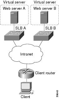
When both web servers in Figure 4-19 are operational, the client router receives the host route from both IOS SLB devices.
If Web Server A fails, the virtual server for the virtual IP address on SLB A enters FAILED state and stops advertising the host route for the virtual IP address. The client router then begins using the route to SLB B.
When Web Server A is again available, the virtual server again advertises the host route for the virtual IP address, and the client router begins using SLB A.
Example: How to Configure Two Distributed Sites with Two Web Servers Each
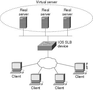
Figure 4-20 shows an IOS SLB network configured with route health injection with the following characteristics:
•![]() Both IOS SLB devices are configured with the same virtual IP address.
Both IOS SLB devices are configured with the same virtual IP address.
•![]() Each IOS SLB device has a server farm containing two locally attached web servers as real servers.
Each IOS SLB device has a server farm containing two locally attached web servers as real servers.
•![]() The path to SLB A has the lower weight.
The path to SLB A has the lower weight.
Figure 4-20 Two Distributed Sites with Two Web Servers Each
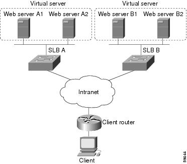
When all web servers in Figure 4-20 are operational, the client router receives the host route from both IOS SLB devices.
If one web server in either server farm fails, the route continues to be advertised by the given IOS SLB device.
If both Web Server A1 and Web Server A2 fail, the virtual server for the virtual IP address on SLB A enters FAILED state and stops advertising the host route for the virtual IP address. The client router then begins using the route to SLB B.
When either Web Server A1 or Web Server A2 is again available, the virtual server again advertises the host route for the virtual IP address, and the client router begins using SLB A.
Example: How to Configure Two Distributed Sites with One Web Server and a Backup IOS SLB Switch Each
Figure 4-21 shows an IOS SLB network configured with route health injection with the following characteristics:
•![]() Both IOS SLB devices are configured with the same virtual IP address.
Both IOS SLB devices are configured with the same virtual IP address.
•![]() Each IOS SLB device has a server farm containing only the locally attached web server as a real server.
Each IOS SLB device has a server farm containing only the locally attached web server as a real server.
•![]() Each site has a primary IOS SLB device and a backup IOS SLB device.
Each site has a primary IOS SLB device and a backup IOS SLB device.
•![]() The path to SLB A has the lower weight.
The path to SLB A has the lower weight.
Figure 4-21 Two Distributed Sites with One Web Server and a Backup IOS SLB Switch Each
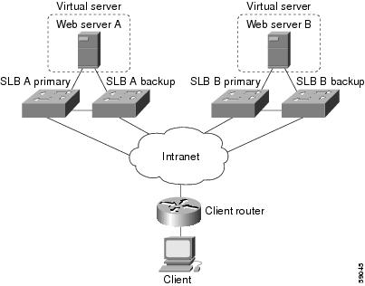
When both web servers in Figure 4-21 are operational, the client router receives the host route from both SLB A Primary and SLB B Primary.
If SLB A Primary fails, SLB A Backup begins advertising the host route to the virtual IP address. If SLB A Backup also fails, the virtual server for the virtual IP address on SLB A Primary and SLB A Backup enters FAILED state and stops advertising the host route for the virtual IP address. The client router then begins using the route to SLB B Primary (or to SLB B Backup, if SLB B Primary is not available).
When either SLB A Primary or SLB A Backup is again available, the virtual server again advertises the host route for the virtual IP address, and the client router begins using SLB A Primary or SLB A Backup.
Examples: How to Configure IOS SLB with GPRS Load Balancing
This section contains the following examples, illustrating several different IOS SLB configurations with redundancy:
•![]() Example: How to Configure IOS SLB with GPRS Load Balancing Without GTP Cause Code Inspection
Example: How to Configure IOS SLB with GPRS Load Balancing Without GTP Cause Code Inspection
•![]() Example: How to Configure IOS SLB with GPRS Load Balancing and NAT
Example: How to Configure IOS SLB with GPRS Load Balancing and NAT
•![]() Example: How to Configure IOS SLB with GPRS Load Balancing, NAT, and GTP Cause Code Inspection
Example: How to Configure IOS SLB with GPRS Load Balancing, NAT, and GTP Cause Code Inspection
•![]() Example: How to Configure IOS SLB with GPRS Load Balancing Maps
Example: How to Configure IOS SLB with GPRS Load Balancing Maps
•![]() Example: How to Configure IOS SLB with Dual-Stack Addresses for GTP Load Balancing
Example: How to Configure IOS SLB with Dual-Stack Addresses for GTP Load Balancing
•![]() Example: How to Configure IOS SLB with RADIUS Load Balancing for a GPRS Network
Example: How to Configure IOS SLB with RADIUS Load Balancing for a GPRS Network
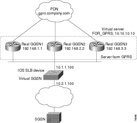
Example: How to Configure IOS SLB with GPRS Load Balancing Without GTP Cause Code Inspection
Figure 4-22 shows a typical GPRS load-balancing configuration without GTP cause code inspection enabled. In this configuration:
•![]() IOS SLB can balance GPRS flows across multiple real GGSNs. The SGSN "sees" the real GGSNs as one virtual GGSN. This configuration increases the flow-handling capability of the real GGSNs and increases the reliability and availability.
IOS SLB can balance GPRS flows across multiple real GGSNs. The SGSN "sees" the real GGSNs as one virtual GGSN. This configuration increases the flow-handling capability of the real GGSNs and increases the reliability and availability.
•![]() The virtual template address of the SGSN is 10.111.111.111.
The virtual template address of the SGSN is 10.111.111.111.
•![]() The virtual template address of GGSN1 is 192.168.1.1.
The virtual template address of GGSN1 is 192.168.1.1.
•![]() The virtual template address of GGSN2 is 192.168.2.2.
The virtual template address of GGSN2 is 192.168.2.2.
•![]() The virtual template address of GGSN3 is 192.168.3.3.
The virtual template address of GGSN3 is 192.168.3.3.
Figure 4-22 IOS SLB with GPRS Load Balancing
Following are the configuration statements for the configuration shown in Figure 4-22:
•![]() IOS SLB Configuration Statements
IOS SLB Configuration Statements
•![]() GGSN1 Configuration Statements
GGSN1 Configuration Statements
•![]() GGSN2 Configuration Statements
GGSN2 Configuration Statements
•![]() GGSN3 Configuration Statements
GGSN3 Configuration Statements
For more detailed GGSN configuration examples, refer to the Cisco IOS Mobile Wireless Configuration Guide.
IOS SLB Configuration Statements
hostname GTP_SLB
!
ip domain-name gprs.com
!
ip slb serverfarm GPRS
real 192.168.1.1
weight 1
faildetect numconns 1 numclients 1
inservice
!
real 192.168.2.2
weight 1
faildetect numconns 1 numclients 1
inservice
!
real 192.168.3.3
weight 1
faildetect numconns 1 numclients 1
inservice
!
ip slb vserver FOR_GPRS
virtual 10.10.10.10 udp 3386 service gtp
serverfarm GPRS
inservice
!
ip slb dfp password Password1 0
agent 10.1.1.201 1111 30 0 10
agent 10.1.1.202 1111 30 0 10
agent 10.1.1.203 1111 30 0 10
!
interface FastEthernet1/0
description TO SERVERFARM GPRS
ip address 10.1.1.100 255.255.255.0
no ip redirects
duplex half
!
interface FastEthernet3/0
description TO SGSN
ip address 10.2.1.100 255.255.255.0
no ip mroute-cache
duplex half
!
ip route 10.111.111.111 255.255.255.255 FastEthernet1/0
ip route 192.168.1.1 255.255.255.255 10.1.1.201
ip route 192.168.2.2 255.255.255.255 10.1.1.202
ip route 192.168.3.3 255.255.255.255 10.1.1.203
GGSN1 Configuration Statements
service gprs ggsn
!
hostname GGSN1
!
ip dfp agent gprs
port 1111
password Password1 0
inservice
!
ip domain-name gprs.com
!
interface loopback 1
description LOOPBACK SAME AS IOS SLB VSERVER ADDRESS
ip address 10.10.10.10 255.255.255.255
no ip route-cache
no ip mroute-cache
!
interface FastEthernet1/0
description TO SLB
ip address 10.1.1.201 255.255.255.0
ip directed-broadcast
no ip mroute-cache
duplex half
!
interface Virtual-Template1
description GTP VIRTUAL TEMPLATE
ip address 192.168.1.1 255.255.255.0
encapsulation gtp
gprs access-point-list gprs1
!
ip route 10.111.111.111 255.255.255.255 FastEthernet1/0
!
gprs access-point-list gprs1
access-point 1
access-point-name gprs.company.com
access-mode non-transparent
ip-address-pool dhcp-proxy-client
dhcp-server 10.100.0.5 10.100.0.6
dhcp-gateway-address 10.27.3.1
exit
!
gprs maximum-pdp-context-allowed 45000
gprs qos map canonical-qos
gprs gtp path-echo-interval 0
gprs dfp max-weight 32
gprs slb cef 10.10.10.10
GGSN2 Configuration Statements
service gprs ggsn
!
hostname GGSN2
!
ip dfp agent gprs
port 1111
password Password1 0
inservice
!
ip domain-name gprs.com
!
interface loopback 1
description LOOPBACK SAME AS IOS SLB VSERVER ADDRESS
ip address 10.10.10.10 255.255.255.255
no ip route-cache
no ip mroute-cache
!
interface FastEthernet1/0
description TO SLB
ip address 10.1.1.202 255.255.255.0
ip directed-broadcast
no ip mroute-cache
duplex half
!
interface Virtual-Template1
description GTP VIRTUAL TEMPLATE
ip address 192.168.2.2 255.255.255.0
encapsulation gtp
gprs access-point-list gprs1
!
ip route 10.111.111.111 255.255.255.255 FastEthernet1/0
!
gprs access-point-list gprs1
access-point 1
access-point-name gprs.company.com
access-mode non-transparent
ip-address-pool dhcp-proxy-client
dhcp-server 10.100.0.5 10.100.0.6
dhcp-gateway-address 10.27.3.1
exit
!
gprs maximum-pdp-context-allowed 45000
gprs qos map canonical-qos
gprs gtp path-echo-interval 0
gprs dfp max-weight 32
gprs slb cef 10.10.10.10
GGSN3 Configuration Statements
service gprs ggsn
!
hostname GGSN3
!
ip dfp agent gprs
port 1111
password Password1 0
inservice
!
ip domain-name gprs.com
!
interface loopback 1
description LOOPBACK SAME AS IOS SLB VSERVER ADDRESS
ip address 10.10.10.10 255.255.255.255
no ip route-cache
no ip mroute-cache
!
interface FastEthernet1/0
description TO SLB
ip address 10.1.1.203 255.255.255.0
ip directed-broadcast
no ip mroute-cache
duplex half
!
interface Virtual-Template1
description GTP VIRTUAL TEMPLATE
ip address 192.168.3.3 255.255.255.0
encapsulation gtp
gprs access-point-list gprs1
!
ip route 10.111.111.111 255.255.255.255 FastEthernet1/0
!
gprs access-point-list gprs1
access-point 1
access-point-name gprs.company.com
access-mode non-transparent
ip-address-pool dhcp-proxy-client
dhcp-server 10.100.0.5 10.100.0.6
dhcp-gateway-address 10.27.3.1
exit
!
gprs maximum-pdp-context-allowed 45000
gprs qos map canonical-qos
gprs gtp path-echo-interval 0
gprs dfp max-weight 32
gprs slb cef 10.10.10.10
Example: How to Configure IOS SLB with GPRS Load Balancing and NAT
The following example uses the same basic configuration as in the "Example: How to Configure IOS SLB with GPRS Load Balancing Without GTP Cause Code Inspection" section, including the network shown in Figure 4-22, but with the addition of NAT:
•![]() IOS SLB Configuration Statements
IOS SLB Configuration Statements
•![]() GGSN1 Configuration Statements
GGSN1 Configuration Statements
•![]() GGSN2 Configuration Statements
GGSN2 Configuration Statements
•![]() GGSN3 Configuration Statements
GGSN3 Configuration Statements
For more detailed GGSN configuration examples, refer to the Cisco IOS Mobile Wireless Configuration Guide.
IOS SLB Configuration Statements
hostname GTP_SLB
!
ip domain-name gprs.com
!
ip slb serverfarm GPRS
nat server
real 192.168.1.1
weight 1
faildetect numconns 1 numclients 1
inservice
!
real 192.168.2.2
weight 1
faildetect numconns 1 numclients 1
inservice
!
real 192.168.3.3
weight 1
faildetect numconns 1 numclients 1
inservice
!
ip slb vserver FOR_GPRS
virtual 10.10.10.10 udp 3386 service gtp
serverfarm GPRS
inservice
!
ip slb dfp password Password1 0
agent 10.1.1.201 1111 30 0 10
agent 10.1.1.202 1111 30 0 10
agent 10.1.1.203 1111 30 0 10
!
interface FastEthernet1/0
description TO SERVERFARM GPRS
ip address 10.1.1.100 255.255.255.0
no ip redirects
duplex half
!
interface FastEthernet3/0
description TO SGSN
ip address 10.2.1.100 255.255.255.0
no ip mroute-cache
duplex half
!
ip route 10.111.111.111 255.255.255.255 FastEthernet1/0
ip route 192.168.1.1 255.255.255.255 10.1.1.201
ip route 192.168.2.2 255.255.255.255 10.1.1.202
ip route 192.168.3.3 255.255.255.255 10.1.1.203
GGSN1 Configuration Statements
service gprs ggsn
!
hostname GGSN1
!
ip dfp agent gprs
port 1111
password Password1 0
inservice
!
ip domain-name gprs.com
!
interface FastEthernet1/0
description TO SLB
ip address 10.1.1.201 255.255.255.0
ip directed-broadcast
no ip mroute-cache
duplex half
!
interface Virtual-Template1
description GTP VIRTUAL TEMPLATE
ip address 192.168.1.1 255.255.255.0
encapsulation gtp
gprs access-point-list gprs1
!
ip route 10.111.111.111 255.255.255.255 FastEthernet1/0
!
gprs access-point-list gprs1
access-point 1
access-point-name gprs.company.com
access-mode non-transparent
ip-address-pool dhcp-proxy-client
dhcp-server 10.100.0.5 10.100.0.6
dhcp-gateway-address 10.27.3.1
exit
!
gprs maximum-pdp-context-allowed 45000
gprs qos map canonical-qos
gprs gtp path-echo-interval 0
gprs dfp max-weight 32
GGSN2 Configuration Statements
service gprs ggsn
!
hostname GGSN2
!
ip dfp agent gprs
port 1111
password Password1 0
inservice
!
ip domain-name gprs.com
!
interface FastEthernet1/0
description TO SLB
ip address 10.1.1.202 255.255.255.0
ip directed-broadcast
no ip mroute-cache
duplex half
interface Virtual-Template1
description GTP VIRTUAL TEMPLATE
ip address 192.168.2.2 255.255.255.0
encapsulation gtp
gprs access-point-list gprs1
!
ip route 10.111.111.111 255.255.255.255 FastEthernet1/0
!
gprs access-point-list gprs1
access-point 1
access-point-name gprs.company.com
access-mode non-transparent
ip-address-pool dhcp-proxy-client
dhcp-server 10.100.0.5 10.100.0.6
dhcp-gateway-address 10.27.3.1
exit
!
gprs maximum-pdp-context-allowed 45000
gprs qos map canonical-qos
gprs gtp path-echo-interval 0
gprs dfp max-weight 32
GGSN3 Configuration Statements
service gprs ggsn
!
hostname GGSN3
!
ip dfp agent gprs
port 1111
password Password1 0
inservice
!
ip domain-name gprs.com
!
interface FastEthernet1/0
description TO SLB
ip address 10.1.1.203 255.255.255.0
ip directed-broadcast
no ip mroute-cache
duplex half
!
interface Virtual-Template1
description GTP VIRTUAL TEMPLATE
ip address 192.168.3.3 255.255.255.0
encapsulation gtp
gprs access-point-list gprs1
!
ip route 10.111.111.111 255.255.255.255 FastEthernet1/0
!
gprs access-point-list gprs1
access-point 1
access-point-name gprs.company.com
access-mode non-transparent
ip-address-pool dhcp-proxy-client
dhcp-server 10.100.0.5 10.100.0.6
dhcp-gateway-address 10.27.3.1
exit
!
gprs maximum-pdp-context-allowed 45000
gprs qos map canonical-qos
gprs gtp path-echo-interval 0
gprs dfp max-weight 32
Example: How to Configure IOS SLB with GPRS Load Balancing, NAT, and GTP Cause Code Inspection
The following example uses the same basic configuration as in the "Example: How to Configure IOS SLB with GPRS Load Balancing and NAT" section, including the network shown in Figure 4-22, but with the GTP cause code inspection enabled. In this configuration:
•![]() The GSN idle timer is set to 20 seconds.
The GSN idle timer is set to 20 seconds.
•![]() The GTP request idle timer is set to 15 seconds.
The GTP request idle timer is set to 15 seconds.
•![]() The virtual server accepts PDP context creates only from International Mobile Subscriber IDs (IMSIs) with carrier code mcc 222 mnc 22.
The virtual server accepts PDP context creates only from International Mobile Subscriber IDs (IMSIs) with carrier code mcc 222 mnc 22.
Following are the configuration statements for the configuration shown in Figure 4-22, with the addition of NAT and GTP cause code inspection support:
•![]() IOS SLB Configuration Statements
IOS SLB Configuration Statements
•![]() GGSN1 Configuration Statements (no change for GTP cause code inspection)
GGSN1 Configuration Statements (no change for GTP cause code inspection)
•![]() GGSN2 Configuration Statements (no change for GTP cause code inspection)
GGSN2 Configuration Statements (no change for GTP cause code inspection)
•![]() GGSN3 Configuration Statements (no change for GTP cause code inspection)
GGSN3 Configuration Statements (no change for GTP cause code inspection)
For more detailed GGSN configuration examples, refer to the Cisco IOS Mobile Wireless Configuration Guide.
IOS SLB Configuration Statements
hostname GTP_SLB
!
ip domain-name gprs.com
!
ip slb timers gtp gsn 20
!
ip slb serverfarm GPRS
nat server
real 192.168.1.1
weight 1
faildetect numconns 1 numclients 1
inservice
!
real 192.168.2.2
weight 1
faildetect numconns 1 numclients 1
inservice
!
real 192.168.3.3
weight 1
faildetect numconns 1 numclients 1
inservice
!
ip slb vserver FOR_GPRS
virtual 10.10.10.10 udp 0 service gtp-inspect
idle gtp request 15
client gtp carrier-code mcc 222 mnc 22
serverfarm GPRS
inservice
!
ip slb dfp password Password1 0
agent 10.1.1.201 1111 30 0 10
agent 10.1.1.202 1111 30 0 10
agent 10.1.1.203 1111 30 0 10
!
interface FastEthernet1/0
description TO SERVERFARM GPRS
ip address 10.1.1.100 255.255.255.0
no ip redirects
duplex half
!
interface FastEthernet3/0
description TO SGSN
ip address 10.2.1.100 255.255.255.0
no ip mroute-cache
duplex half
!
ip route 10.111.111.111 255.255.255.255 FastEthernet1/0
ip route 192.168.1.1 255.255.255.255 10.1.1.201
ip route 192.168.2.2 255.255.255.255 10.1.1.202
ip route 192.168.3.3 255.255.255.255 10.1.1.203
Example: How to Configure IOS SLB with GPRS Load Balancing Maps
The following sample configuration enables IOS SLB to support multiple server farms behind a GPRS load balancing virtual server, using access point names (APNs) to select server farms. Server farm farm6 is configured without an associated map, and therefore acts as a default server farm. If IOS SLB cannot match any of the other server farm maps, and a default server farm is configured, IOS SLB sends the GPRS request to the default serverfarm.
ip slb map 1 gtp
apn cisco*
ip slb map 4 gtp
apn abc.microsoft.com
apn xyz.intel.com
ip slb map 5 gtp
apn yahoo.com
!
ip slb serverfarm farm1
real 10.0.0.1
inservice
real 10.0.0.2
inservice
ip slb serverfarm farm2
real 10.0.0.3
inservice
real 10.0.0.4
inservice
ip slb serverfarm farm3
real 10.0.0.5
inservice
real 10.0.0.6
inservice
ip slb serverfarm farm4
real 10.0.0.7
inservice
real 10.0.0.8
inservice
ip slb serverfarm farm5
real 10.0.0.9
inservice
real 10.0.0.10
inservice
ip slb serverfarm farm6
real 10.0.0.11
inservice
!
ip slb map 1 gtp
apn cisco*
ip slb map 4 gtp
apn abc.microsoft.com
apn xyz.intel.com
ip slb map 5 gtp
apn yahoo.com
!
ip slb vserver GGSN_SERVER
virtual 10.10.10.10 udp 0 service gtp
serverfarm farm1 backup farm2 map 1 priority 3
serverfarm farm4 map 4 priority 1
serverfarm farm5 map 5 priority 4
serverfarm farm6
inservice
Example: How to Configure IOS SLB with Dual-Stack Addresses for GTP Load Balancing
The following sample configuration enables IOS SLB to support dual-stack addresses for GTP load balancing.
ip slb serverfarm SF1
real 172.16.88.5
weight 1
inservice
!
ip slb serverfarm SF2
real 172.16.88.6
weight 1
inservice
!
ip slb serverfarm SF3
real 172.16.88.7 ipv6 2342:2342:2343:FF04:2388:BB03:3329:8612
weight 1
inservice
!
ip slb serverfarm SF4
real 172.16.88.8 ipv6 2342:2342:2343:FF04:2388:BB03:3423:8912
weight 1
inservice
!
ip slb vserver VS2
virtual 4.3.2.1 ipv6 2342:2342:2343:FF04:2341:AA03:2323:8912 udp 0 service gtp
serverfarm sf1 backup sf2 ipv6-primary sf3 ipv6-backup sf4
idle gtp request 90
idle gtp imsi 10000000
sticky gtp imsi group 1
gtp notification cac 3
inservice
Example: How to Configure IOS SLB with VPN Server Load Balancing
Figure 4-23 shows a typical VPN server load-balancing configuration. In this configuration:
•![]() VPN flows are balanced between real servers 20.20.20.10 and 20.20.20.20.
VPN flows are balanced between real servers 20.20.20.10 and 20.20.20.20.
•![]() Clients connect to 10.10.1.1, the IOS SLB virtual server address.
Clients connect to 10.10.1.1, the IOS SLB virtual server address.
•![]() There is a sticky connection between the ESP virtual server and the UDP virtual server.
There is a sticky connection between the ESP virtual server and the UDP virtual server.
•![]() The cryptographic key exchange occurs through IKE (ISAKMP; port 500).
The cryptographic key exchange occurs through IKE (ISAKMP; port 500).
Figure 4-23 IOS SLB with VPN Server Load Balancing
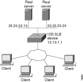
Following are the IOS SLB configuration statements for the configuration shown in Figure 4-23:
ip slb serverfarm VPN
nat server
real 20.20.20.10
inservice
real 20.20.20.20
inservice
failaction purge
!
ip slb vserver ESP
virtual 10.10.1.1 ESP
serverfarm VPN
sticky 3600 group 69
inservice
!
ip slb vserver UDP
virtual 10.10.1.1 UDP isakmp
serverfarm VPN
sticky 3600 group 69
inservice
Examples: How to Configure IOS SLB with RADIUS Load Balancing
This section contains the following examples, illustrating several different IOS SLB RADIUS load-balancing configurations:
•![]() Example: How to Configure IOS SLB with RADIUS Load Balancing for a GPRS Network
Example: How to Configure IOS SLB with RADIUS Load Balancing for a GPRS Network
•![]() Example: How to Configure IOS SLB with RADIUS Load Balancing for a Simple IP CDMA2000 Network
Example: How to Configure IOS SLB with RADIUS Load Balancing for a Simple IP CDMA2000 Network
•![]() Example: How to Configure IOS SLB with RADIUS Load Balancing for a Mobile IP CDMA2000 Network
Example: How to Configure IOS SLB with RADIUS Load Balancing for a Mobile IP CDMA2000 Network
•![]() Example: How to Configure IOS SLB with RADIUS Load Balancing for Multiple Service Gateway Farms
Example: How to Configure IOS SLB with RADIUS Load Balancing for Multiple Service Gateway Farms
•![]() Example: How to Configure IOS SLB with RADIUS Load Balancing/Firewall Load Balancing "Sandwich"
Example: How to Configure IOS SLB with RADIUS Load Balancing/Firewall Load Balancing "Sandwich"
•![]() Example: How to Configure IOS SLB with RADIUS Load Balancing Maps
Example: How to Configure IOS SLB with RADIUS Load Balancing Maps
•![]() Example: How to Configure IOS SLB with RADIUS Load Balancing Accelerated Data Plane Forwarding
Example: How to Configure IOS SLB with RADIUS Load Balancing Accelerated Data Plane Forwarding
Example: How to Configure IOS SLB with RADIUS Load Balancing for a GPRS Network
Figure 4-24 shows a typical IOS SLB RADIUS load-balancing configuration for a GPRS network. In this configuration:
•![]() RADIUS requests are load-balanced between SSG RADIUS proxy servers 10.10.10.1 and 10.10.10.2.
RADIUS requests are load-balanced between SSG RADIUS proxy servers 10.10.10.1 and 10.10.10.2.
•![]() End-user data packets are routed to the IOS SLB device.
End-user data packets are routed to the IOS SLB device.
•![]() End-user data packets from the 1.1.1.0 subnet are directed by IOS SLB to SSG1.
End-user data packets from the 1.1.1.0 subnet are directed by IOS SLB to SSG1.
•![]() End-user data packets from the 1.1.2.0 subnet are directed by IOS SLB to SSG2.
End-user data packets from the 1.1.2.0 subnet are directed by IOS SLB to SSG2.
Figure 4-24 IOS SLB with RADIUS Load Balancing for a GPRS Network
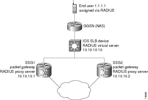
Following are the IOS SLB configuration statements for the configuration shown in Figure 4-24:
ip slb route 1.1.0.0 255.255.0.0 framed-ip
!
ip slb serverfarm SSGFARM
nat server
real 10.10.10.1
inservice
real 10.10.10.2
inservice
!
ip slb vserver RADIUS_ACCT
virtual 10.10.10.10 udp 1813 service radius
serverfarm SSGFARM
idle radius request 20
idle radius framed-ip 7200
sticky radius framed-ip group 1
inservice
!
ip slb vserver RADIUS_AUTH
virtual 10.10.10.10 udp 1812 service radius
serverfarm SSGFARM
idle radius request 20
idle radius framed-ip 7200
sticky radius framed-ip group 1
inservice
Example: How to Configure IOS SLB with RADIUS Load Balancing for a Simple IP CDMA2000 Network
Figure 4-25 shows a typical IOS SLB RADIUS load-balancing configuration for a CDMA2000 network with simple IP service. In this configuration:
•![]() The RADIUS virtual server IP address for the PDSNs is 10.10.10.10.
The RADIUS virtual server IP address for the PDSNs is 10.10.10.10.
•![]() RADIUS requests are load-balanced between SSG RADIUS proxy servers 10.10.10.1 and 10.10.10.2.
RADIUS requests are load-balanced between SSG RADIUS proxy servers 10.10.10.1 and 10.10.10.2.
•![]() End-user data packets are routed to the IOS SLB device.
End-user data packets are routed to the IOS SLB device.
•![]() End-user data packets from the 1.1.0.0 network are routed to the SSGs.
End-user data packets from the 1.1.0.0 network are routed to the SSGs.
Figure 4-25 IOS SLB with RADIUS Load Balancing for a Simple IP CDMA2000 Network
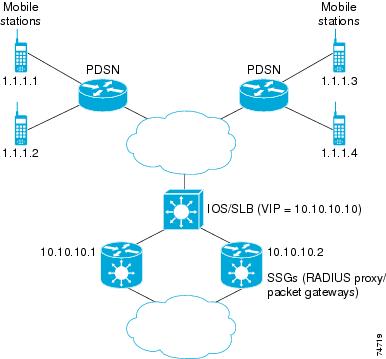
Following are the IOS SLB configuration statements for the configuration shown in Figure 4-25:
ip slb route 1.1.0.0 255.255.0.0 framed-ip
!
ip slb serverfarm SSGFARM
nat server
real 10.10.10.1
inservice
real 10.10.10.2
inservice
!
ip slb vserver RADIUS_SIP
virtual 10.10.10.10 udp 0 service radius
serverfarm SSGFARM
idle radius framed-ip 3600
sticky radius username
sticky radius framed-ip
inservice
Example: How to Configure IOS SLB with RADIUS Load Balancing for a Mobile IP CDMA2000 Network
Figure 4-26 shows a typical IOS SLB RADIUS load-balancing configuration for a CDMA2000 network with Mobile IP service. In this configuration:
•![]() The RADIUS virtual server IP address for the PDSNs and the HA is 10.10.10.10.
The RADIUS virtual server IP address for the PDSNs and the HA is 10.10.10.10.
•![]() RADIUS requests are load-balanced between SSG RADIUS proxy servers 10.10.10.1 and 10.10.10.2.
RADIUS requests are load-balanced between SSG RADIUS proxy servers 10.10.10.1 and 10.10.10.2.
•![]() End-user data packets are routed to the IOS SLB device.
End-user data packets are routed to the IOS SLB device.
•![]() End-user data packets from the 1.1.0.0 network are routed to the SSGs.
End-user data packets from the 1.1.0.0 network are routed to the SSGs.
Figure 4-26 IOS SLB with RADIUS Load Balancing for a Mobile IP CDMA2000 Network
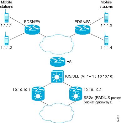
Following are the IOS SLB configuration statements for the configuration shown in Figure 4-26:
ip slb route 1.1.0.0 255.255.0.0 framed-ip
!
ip slb serverfarm SSGFARM
nat server
real 10.10.10.1
inservice
real 10.10.10.2
inservice
!
ip slb vserver RADIUS_SIP
virtual 10.10.10.10 udp 0 service radius
serverfarm SSGFARM
idle radius framed-ip 3600
sticky radius username
sticky radius framed-ip
inservice
Example: How to Configure IOS SLB with RADIUS Load Balancing for Multiple Service Gateway Farms
The following sample configuration enables IOS SLB to balance packet flows for a set of subscribers among multiple service gateway server farms (in this sample, a server farm of SSGs and a server farm of CSGs):
ip slb route 1.1.0.0 255.255.0.0 framed-ip
!
ip slb serverfarm SSGFARM
nat server
real 10.10.10.1
inservice
real 10.10.10.2
inservice
!
ip slb serverfarm CSGFARM
nat server
real 20.20.20.1
inservice
real 20.20.20.2
inservice
!
ip slb vserver SSG_AUTH
virtual 10.10.10.10 udp 1812 service radius
serverfarm SSGFARM
idle radius request 20
idle radius framed-ip 7200
sticky radius framed-ip group 1
access Vlan20 route framed-ip
inservice
!
ip slb vserver SSG_ACCT
virtual 10.10.10.10 udp 1813 service radius
serverfarm SSGFARM
idle radius request 20
idle radius framed-ip 7200
sticky radius framed-ip group 1
access Vlan20 route framed-ip
inservice
!
ip slb vserver CSG_ACCT
virtual 20.20.20.20 udp 1813 service radius
serverfarm CSGFARM
idle radius request 25
idle radius framed-ip 0
sticky radius framed-ip
access Vlan30 route framed-ip
inservice
Example: How to Configure IOS SLB with RADIUS Load Balancing/Firewall Load Balancing "Sandwich"
Figure 4-27 shows a RADIUS load balancing/firewall load balancing "sandwich" on one IOS SLB device. In this sample configuration:
•![]() The RADIUS load balancing virtual IP address is 5.5.5.5.
The RADIUS load balancing virtual IP address is 5.5.5.5.
•![]() The subscriber framed-IP network is 1.0.0.0/255.0.0.0.
The subscriber framed-IP network is 1.0.0.0/255.0.0.0.
•![]() VL105, VL106, VL107, and VL108 are VLANs.
VL105, VL106, VL107, and VL108 are VLANs.
•![]() RADIUS requests arriving on VLAN VL105 are balanced to 10.10.106.42 and 10.10.106.43.
RADIUS requests arriving on VLAN VL105 are balanced to 10.10.106.42 and 10.10.106.43.
•![]() User traffic is stickied based on framed-IP address assignments in the 1.0.0.0 subnet.
User traffic is stickied based on framed-IP address assignments in the 1.0.0.0 subnet.
•![]() Firewall load balancing on the other side (10.10.107.42/43) ensures that return path traffic to the subscriber is delivered to the correct gateway.
Firewall load balancing on the other side (10.10.107.42/43) ensures that return path traffic to the subscriber is delivered to the correct gateway.
Figure 4-27 IOS SLB with RADIUS Load Balancing/Firewall Load Balancing "Sandwich"
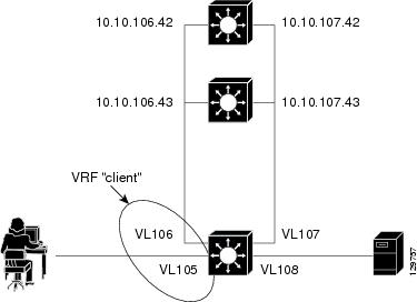
Following are the IOS SLB configuration statements for the configuration shown in Figure 4-27:
ip vrf client
rd 0:1
!
ip slb probe P742 ping
address 10.10.107.42
interval 120
!
ip slb probe P743 ping
address 10.10.107.43
interval 120
!
ip slb route 1.0.0.0 255.0.0.0 framed-ip
ip slb route framed-ip deny
!
ip slb firewallfarm SERVER
access inbound Vlan108
access outbound Vlan107
inservice
real 10.10.107.42
probe P742
inservice
real 10.10.107.43
probe P743
inservice
protocol tcp
sticky 180 destination
protocol datagram
sticky 180 destination
predictor hash address port
!
ip slb serverfarm SF1
nat server
access Vlan106
!
real 10.10.106.42
inservice
real 10.10.106.43
inservice
!
ip slb vserver VS1
virtual 5.5.5.5 udp 0 service radius
serverfarm SF1
sticky radius framed-ip
access Vlan105 route framed-ip
access Vlan105
inservice
!
mls flow ip interface-full
!
!*************************************************
!* Switchports, port channels and trunks *
!* added to vlans 105-108 (left out for brevity) *
!*************************************************
!
interface Vlan105
ip vrf forwarding client
ip address 10.10.105.2 255.255.255.0
!
interface Vlan106
ip vrf forwarding client
ip address 10.10.106.2 255.255.255.0
!
interface Vlan107
ip address 10.10.107.2 255.255.255.0
!
interface Vlan108
ip address 10.10.108.2 255.255.255.0
!
ip route 10.10.105.0 255.255.255.0 10.10.107.42
ip route vrf client 10.10.108.0 255.255.255.0 10.10.106.42
Example: How to Configure IOS SLB with RADIUS Load Balancing Maps
The following sample configuration enables IOS SLB to support multiple server farms behind a RADIUS load balancing virtual server, using RADIUS calling station IDs and usernames to select server farms. Server farm farm3 is configured without an associated map, and therefore acts as a default server farm. If IOS SLB cannot match any of the other server farm maps, and a default server farm is configured, IOS SLB sends the RADIUS request to the default serverfarm.
ip slb serverfarm CSGFARM
predictor route-map rlb-pbr
ip slb serverfarm AAAFARM
nat server
real 10.10.10.1
inservice
real 10.10.10.2
inservice
ip slb vserver RADIUS_ACCT
virtual 10.10.10.10 udp 1813 service radius
serverfarm CSGFARM
radius inject acct 1 key 0 cisco
inservice
ip slb vserver RADIUS_AUTH
virtual 10.10.10.10 udp 1812 service radius
serverfarm AAAFARM
radius inject auth 1 calling-station-id
radius inject auth timer 45
radius inject auth vsa cisco
inservice
!
interface vlan 100
ip policy route-map rlb-pbr
!
access-list 1 permit 0.0.0.1 255.255.255.254
access-list 2 permit 0.0.0.0 255.255.255.254
!
route-map rlb-pbr permit 10
match ip address 1
set ip next-hop 10.10.10.1
!
route-map rlb-pbr permit 20
match ip address 2
set ip next-hop 10.10.10.2
Example: How to Configure IOS SLB with RADIUS Load Balancing Accelerated Data Plane Forwarding
The following IOS SLB configuration has the following characteristics:
•![]() There is a virtual RADIUS server with IP address 10.10.10.10 that manages Network Access Server (NAS) devices.
There is a virtual RADIUS server with IP address 10.10.10.10 that manages Network Access Server (NAS) devices.
•![]() There are two packet gateways with IP addresses 10.10.10.1 and 10.10.10.2.
There are two packet gateways with IP addresses 10.10.10.1 and 10.10.10.2.
•![]() RADIUS traffic destined for the virtual RADIUS server is distributed between the packet gateways, based on mapped framed-IP addresses, according to route map rlb-pbr.
RADIUS traffic destined for the virtual RADIUS server is distributed between the packet gateways, based on mapped framed-IP addresses, according to route map rlb-pbr.
•![]() Server farm CSGFARM is configured with real IP addresses that match the possible results for route map rlb-pbr.
Server farm CSGFARM is configured with real IP addresses that match the possible results for route map rlb-pbr.
•![]() End user traffic arriving on VLAN 100 is routed to the correct Cisco Content Services Gateway (CSG) based on access control lists (ACLs):
End user traffic arriving on VLAN 100 is routed to the correct Cisco Content Services Gateway (CSG) based on access control lists (ACLs):
–![]() ACL 1 sends IP addresses ending in odd numbers to the CSGs behind packet gateway 10.10.10.1.
ACL 1 sends IP addresses ending in odd numbers to the CSGs behind packet gateway 10.10.10.1.
–![]() ACL 2 sends IP addresses ending in even numbers to the CSGs behind packet gateway 10.10.10.2.
ACL 2 sends IP addresses ending in even numbers to the CSGs behind packet gateway 10.10.10.2.
Figure 4-28 IOS SLB with RADIUS Load Balancing Accelerated Data Plane Forwarding
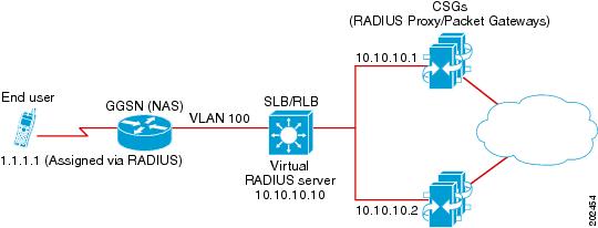
Following are the IOS SLB configuration statements for the configuration shown in Figure 4-28:
ip slb serverfarm CSGFARM
predictor route-map rlb-pbr
ip slb serverfarm AAAFARM
nat server
real 10.10.10.1
inservice
real 10.10.10.2
inservice
!
ip slb vserver RADIUS_ACCT
virtual 10.10.10.10 udp 1813 service radius
serverfarm CSGFARM
radius inject acct 1 key 0 cisco
inservice
!
ip slb vserver RADIUS_AUTH
virtual 10.10.10.10 udp 1812 service radius
serverfarm AAAFARM
radius inject auth 1 calling-station-id
radius inject auth timer 45
radius inject auth vsa cisco
inservice
!
interface vlan 100
ip policy route-map rlb-pbr
!
access-list 1 permit 0.0.0.1 255.255.255.254
access-list 2 permit 0.0.0.0 255.255.255.254
!
route-map rlb-pbr permit 10
match ip address 1
set ip next-hop 10.10.10.1
!
route-map rlb-pbr permit 20
match ip address 2
set ip next-hop 10.10.10.2
Example: How to Configure IOS SLB with Home Agent Director
The following sample configuration enables IOS SLB to balance Mobile IP RRQs among multiple home agents.
Figure 4-29 IOS SLB with Home Agent Director
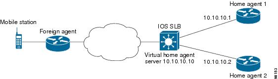
Following are the IOS SLB configuration statements for the configuration shown in Figure 4-29:
ip slb serverfarm HA_FARM
nat server
real 10.10.10.1
inservice
real 10.10.10.2
inservice
ip slb vserver VIRTUAL_HA
virtual 10.10.10.10 udp 434 service ipmobile
serverfarm HA_FARM
inservice
Example: How to Configure IOS SLB with Sticky Connections
The following sample configuration assigns all HTTP connections from a subnet to the same real server in server farm PUBLIC:
ip slb vserver http
serverfarm PUBLIC
sticky 30 group 1 netmask 255.255.255.248
virtual 20.20.20.20 tcp 80
inservice
The following sample configuration adds HTTPS connections to the above configuration, using the same sticky information but with a different virtual server:
ip slb vserver https
serverfarm PUBLIC
sticky 30 group 1 netmask 255.255.255.248
virtual 20.20.20.20 tcp 443
inservice
Now, all HTTP and HTTPS connections from the subnet are assigned to the same real server. For example, if a user connects to HTTP, then a second user connects to HTTPS, both connections are assigned to the same real server.
Example: How to Configure IOS SLB with GTP IMSI Sticky Database
The following sample configuration shows how to enable the IOS SLB GTP IMSI sticky database:
ip slb serverfarm GGSN_FARM
failaction gtp purge
real 10.20.10.1
weight 1
faildetect numconns 255 numclients 8
inservice
!
real 10.20.10.2
weight 1
faildetect numconns 255 numclients 8
inservice
!
real 10.20.10.3
weight 1
faildetect numconns 255 numclients 8
inservice
!
ip slb vserver GGSN_SERVER1
virtual 10.10.10.10 udp 3386 service gtp
serverfarm GGSN_FARM backup GGSN_FARM
idle gtp request 90
idle gtp imsi 10000000
sticky gtp imsi group 1
gtp notification cac 3
inservice
!
ip slb vserver GGSN_SERVER2
virtual 10.10.10.10 udp 2123 service gtp
serverfarm GGSN_FARM backup GGSN_FARM
idle gtp request 90
idle gtp imsi 10000000
sticky gtp imsi group 1
gtp notification cac 3
inservice
Example: How to Configure IOS SLB with ASN Sticky Database
The following sample configuration shows how to enable the IOS SLB ASN sticky database:
ip slb entries sticky 15000 800000
ip slb serverfarm ASNLB_FARM
failaction asn purge
!
real 10.20.10.1
weight 1
faildetect numconns 255 numclients 8
inservice
!
real 10.20.10.2
weight 1
faildetect numconns 255 numclients 8
inservice
!
real 10.20.10.3
weight 1
faildetect numconns 255 numclients 8
inservice
!
ip slb vserver ASNLB_SERVER
virtual 10.10.10.10 udp 0 service asn
serverfarm ASNLB_FARM
idle asn request 90
idle asn msid 100000
sticky asn msid group 1
gw port 63082
replicate casa 100.100.100.102 100.100.100.101 1024 password hello
inservice
Example: How to Configure IOS SLB with Transparent Web Cache Load Balancing
In the following sample configuration, virtual server WEBCACHE examines all web flows passing through the load-balancing device and dispatches them to server farm WEBCACHE-FARM. The client exclude statement ignores flows originating from subnet 80.80.7.0, enabling the real servers 80.80.7.188 and 80.80.7.189 to communicate with the Internet as needed.
ip slb serverfarm WEBCACHE-FARM
real 80.80.7.188
inservice
real 80.80.7.189
inservice
ip slb vserver WEBCACHE
virtual 0.0.0.0 0.0.0.0 tcp www
serverfarm WEBCACHE-FARM
client 80.80.7.0 255.255.255.0 exclude
inservice
Example: How to Configure IOS SLB with KAL-AP Agent
In the following sample configuration, the client is configured to send a Domain Name System (DNS) query abcd.com to the GSS. The Global Site Selector (GSS) in the DUBLIN site receives the requests from the client. The GSS answers the DNS query with the virtual IP address of either CHICAGO (10.0.0.100) or NEWYORK (10.0.0.200), based on the load reported by those virtual servers.
Figure 4-30 IOS SLB with KAL-AP Agent
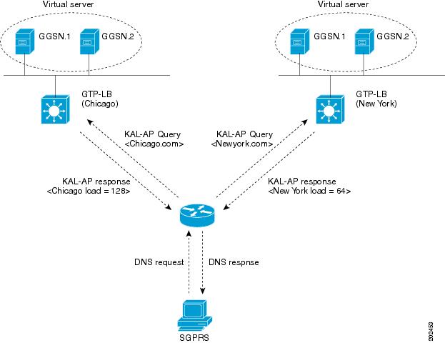
Following are the IOS SLB configuration statements for the configuration shown in Figure 4-30:
GSS
shared-keepalive kalap 192.168.1.1 capp-secure enable key kap
shared-keepalive kalap 192.168.2.1 capp-secure enable key kap
!
answer vip 10.0.0.100 name CHICAGO activate
keepalive type kalap tag 192.168.1.1 chicao.com
answer vip 10.0.0.200 name NEWYORK activate
keepalive type kalap tag 192.168.2.1 newyork.com
!
answer-group ABCD owner System type vip
answer-add 10.0.0.100 name CHICAGO weight 1 order 0 load-threshold 254 activate
answer-add 10.0.0.200 name NEWYORK weight 1 order 0 load-threshold 254 activate
dns rule ABCDGPRS owner System source-address-list Anywhere domain-list abcd.com query a
clause 1 vip-group method least-loaded ttl 20 count 1 sticky disable
Site-1: IOS SLB - CHICAGO
ip slb capp udp
peer port 6000 secret 0 kap
!
ip slb serverfarm SF
kal-ap domain chicago.com
farm-weight 200
real 10.10.10.1
inservice
real 10.10.10.2
inservice
!
ip slb vserver chicago
virtual 10.0.0.100 udp 0
serverfarm SF
inservice
!
ip slb dfp
agent 10.10.10.1 5000 30 0 10
agent 10.10.10.2 5000 30 0 10
!
int vlan100
ip address 192.168.1.1 255.255.255.0
GGSN-1
gprs dfp max-weight 100
gprs maximum-pdp-context-allowed 20000
!
ip dfp agent gprs
port 5000
inservice
GGSN-2
gprs dfp max-weight 100
gprs maximum-pdp-context-allowed 20000
!
ip dfp agent gprs
port 5000
inservice
Site-2: IOS SLB - NEWYORK
ip slb capp udp
peer port 6000
peer 192.1.1.1 secret 0 test
peer 10.100.100.100 port 1234
!
ip slb serverfarm SF
kal-ap domain newyork.com
farm-weight 6200
real 10.20.20.1
inservice
real 10.20.20.2
inservice
real 10.20.20.3
inservice
real 10.20.20.4
inservice
!
ip slb vserver chicago
virtual 10.0.0.200 udp 0
serverfarm SF
inservice
!
ip slb dfp
agent 10.10.10.1 5000 30 0 10
agent 10.10.10.2 5000 30 0 10
!
int vlan200
ip address 192.168.2.1 255.255.255.0
GGSN-1
gprs dfp max-weight 100
gprs maximum-pdp-context-allowed 20000
!
ip dfp agent gprs
port 5000
inservice
GGSN-2
gprs dfp max-weight 100
gprs maximum-pdp-context-allowed 20000
!
ip dfp agent gprs
port 5000
inservice
 Feedback