- Finding Feature Information
- Contents
- Prerequisites for Load Sharing MPLS VPN Traffic
- Restrictions for Load Sharing MPLS VPN Traffic
- Information About Load Sharing MPLS VPN Traffic
- How to Configure Load Sharing
- Configuring BGP Multipath Load Sharing for eBGP and iBGP
- Verifying BGP Multipath Load Sharing for eBGP and iBGP
- Configuring eBGP Multipath Load Sharing with MPLS VPN Inter-AS
- Configuring eBGP Multipath Load Sharing with MPLS VPN Carrier Supporting Carrier on the CSC-PE Routers
- Configuring eBGP Multipath Load Sharing with MPLS VPN Carrier Supporting Carrier on the CSC-CE Routers
- Configuring Directly Connected Loopback Peering for MPLS VPN Inter-AS using ASBRs to Exchange VPN-IPv4 Addresses
- Configuring Directly Connected Loopback Peering for MPLS VPN Inter-AS Using ASBRs to Exchange IPv4 Routes and Labels
- Configuring Directly Connected Loopback Peering on MPLS VPN Carrier Supporting Carrier
- Configuring Loopback Interface Addresses on CSC-PE Routers
- Configuring Loopback Interface Addresses for CSC-CE Routers
- Configuring /32 Static Routes to the eBGP Neighbor Loopback on the CSC-PE Router
- Configuring /32 Static Routes to the eBGP Neighbor Loopback on the CSC-CE Router
- Configuring Forwarding on CSC-PE Interfaces That Connect to the CSC-CE Loopback
- Configuring Forwarding on CSC-CE Interfaces That Connect to the CSC-PE Loopback
- Configuring an eBGP Session Between the CSC-PE Router and the CSC-CE Loopback
- Configuring an eBGP Session Between the CSC-CE Router and the CSC-PE Loopback
- Verifying That Load Sharing Occurs Between Loopbacks
- Configuring a Router to Select eBGP or iBGP Paths as Multipaths: Example
- Configuring a /32 Static Route from an ASBR to the Loopback Address of Another ASBR: Examples
- Configuring BGP/MPLS Forwarding on the Interfaces Connecting ASBRs: Example
- Configuring VPNv4 Sessions on an ASBR: Example
- Verifying VPN NLRI for a Specified Network: Example
Load Sharing MPLS VPN Traffic
Load sharing distributes traffic so that no individual router is overburdened. In a Multiprotocol Label Switching (MPLS) Virtual Private Network (VPN) network, you can achieve load sharing through the following methods:
•![]() BGP multipath options
BGP multipath options
•![]() Directly connected loopback peering
Directly connected loopback peering
Finding Feature Information
Your software release may not support all the features documented in this module. For the latest feature information and caveats, see the release notes for your platform and software release. To find information about the features documented in this module, and to see a list of the releases in which each feature is supported, see the "Feature Information for Load Sharing MPLS VPN Traffic" section.
Use Cisco Feature Navigator to find information about platform support and Cisco IOS and Catalyst OS software image support. To access Cisco Feature Navigator, go to http://www.cisco.com/go/cfn. An account on Cisco.com is not required.
Contents
•![]() Prerequisites for Load Sharing MPLS VPN Traffic
Prerequisites for Load Sharing MPLS VPN Traffic
•![]() Restrictions for Load Sharing MPLS VPN Traffic
Restrictions for Load Sharing MPLS VPN Traffic
•![]() Information About Load Sharing MPLS VPN Traffic
Information About Load Sharing MPLS VPN Traffic
•![]() How to Configure Load Sharing
How to Configure Load Sharing
•![]() Configuration Examples for Load Sharing MPLS VPN Traffic
Configuration Examples for Load Sharing MPLS VPN Traffic
•![]() Feature Information for Load Sharing MPLS VPN Traffic
Feature Information for Load Sharing MPLS VPN Traffic
Prerequisites for Load Sharing MPLS VPN Traffic
Before configuring load sharing, ensure that your MPLS VPN network (including MPLS VPN carrier supporting carrier or interautonomous system) is configured and working properly. See the "Related Documents" section for references related to MPLS VPNs.
Restrictions for Load Sharing MPLS VPN Traffic
•![]() Configuring BGP multipath for eBGP and iBGP is only for basic MPLS Layer 3 VPNs. MPLS VPN Inter-AS and MPLS VPN carrier supporting carrier do not support this multipath configuration.
Configuring BGP multipath for eBGP and iBGP is only for basic MPLS Layer 3 VPNs. MPLS VPN Inter-AS and MPLS VPN carrier supporting carrier do not support this multipath configuration.
•![]() With multiple iBGP paths installed in a routing table, a route reflector advertises only one of the paths (one next hop). If a router is behind a route reflector, all routers that are connected to multihomed sites are not advertised unless separate VRFs with different RDs are configured for each VRF.
With multiple iBGP paths installed in a routing table, a route reflector advertises only one of the paths (one next hop). If a router is behind a route reflector, all routers that are connected to multihomed sites are not advertised unless separate VRFs with different RDs are configured for each VRF.
•![]() Each IP routing table entry for a BGP prefix that has multiple iBGP paths uses additional memory. We recommend not using this feature on a router with a low amount of available memory and especially when the router is carrying a full Internet routing table.
Each IP routing table entry for a BGP prefix that has multiple iBGP paths uses additional memory. We recommend not using this feature on a router with a low amount of available memory and especially when the router is carrying a full Internet routing table.
•![]() eBGP Multipath is not supported on MPLS VPN Inter-AS with ASBRs that exchange VPNv4 routes.
eBGP Multipath is not supported on MPLS VPN Inter-AS with ASBRs that exchange VPNv4 routes.
•![]() Load sharing using directly connected loopback peering does not apply to CSC networks that use LDP and an IGP to distribute routes and MPLS labels.
Load sharing using directly connected loopback peering does not apply to CSC networks that use LDP and an IGP to distribute routes and MPLS labels.
When you configure static routes in an MPLS or MPLS VPN environment, some variations of the ip route and ip route vrf commands are not supported. These variations of the commands are not supported in Cisco IOS releases that support the Tag Forwarding Information Base (TFIB), specifically Cisco IOS Releases 12.nT, 12.nM, and 12.0S. The TFIB cannot resolve prefixes when the recursive route over which the prefixes travel disappears and then reappears. However, the command variations are supported in Cisco IOS releases that support the MPLS Forwarding Infrastructure (MFI), specifically Cisco IOS Release 12.2(25)S and later releases. Use the following guidelines when configuring static routes.
Supported Static Routes in an MPLS Environment
The following ip route command is supported when you configure static routes in an MPLS environment:
ip route destination-prefix mask interface next-hop-address
The following ip route commands are supported when you configure static routes in an MPLS environment and configure load sharing with static nonrecursive routes and a specific outbound interface:
ip route destination-prefix mask interface1 next-hop1
ip route destination-prefix mask interface2 next-hop2
Unsupported Static Routes in an MPLS Environment That Uses the TFIB
The following ip route command is not supported when you configure static routes in an MPLS environment:
ip route destination-prefix mask next-hop-address
The following ip route command is not supported when you configure static routes in an MPLS VPN environment and enable load sharing where the next hop can be reached through two paths:
ip route destination-prefix mask next-hop-address
The following ip route command is not supported when you configure static routes in an MPLS VPN environment and enable load sharing where the destination can be reached through two next hops:
ip route destination-prefix mask next-hop1
ip route destination-prefix mask next-hop2
Use the interface and next-hop arguments when specifying static routes.
Supported Static Routes in an MPLS VPN Environment
The following ip route vrf commands are supported when you configure static routes in an MPLS VPN environment, and the next hop and interface are associated with the same virtual routing and forwarding (VRF) instance:
–![]() ip route vrf vrf-name destination-prefix mask next-hop-address
ip route vrf vrf-name destination-prefix mask next-hop-address
–![]() ip route vrf vrf-name destination-prefix mask interface next-hop-address
ip route vrf vrf-name destination-prefix mask interface next-hop-address
–![]() ip route vrf vrf-name destination-prefix mask interface1 next-hop1
ip route vrf vrf-name destination-prefix mask interface1 next-hop1
ip route vrf vrf-name destination-prefix mask interface2 next-hop2
The following ip route vrf commands are supported when you configure static routes in an MPLS VPN environment, and the next hop is in the global table in the MPLS cloud in the global routing table. For example, these commands are supported when the next hop is pointing to the internet gateway.
–![]() ip route vrf vrf-name destination-prefix mask next-hop-address global
ip route vrf vrf-name destination-prefix mask next-hop-address global
–![]() ip route vrf vrf-name destination-prefix mask interface next-hop-address
ip route vrf vrf-name destination-prefix mask interface next-hop-address
(This command is supported when the next hop and the interface are in the core.)
The following ip route commands are supported when you configure static routes in an MPLS VPN environment and enable load sharing with static nonrecursive routes and a specific outbound interfaces:
ip route destination-prefix mask interface1 next-hop1
ip route destination-prefix mask interface2 next-hop2
Unsupported Static Routes in an MPLS VPN Environment That Uses the TFIB
The following ip route command is not supported when you configure static routes in an MPLS VPN environment, the next hop is in the global table in the MPLS cloud within the core, and you enable load sharing where the next hop can be reached through two paths:
ip route vrf destination-prefix mask next-hop-address global
The following ip route commands are not supported when you configure static routes in an MPLS VPN environment, the next hop is in the global table in the MPLS cloud within the core, and you enable load sharing where the destination can be reached through two next hops:
ip route vrf destination-prefix mask next-hop1 global
ip route vrf destination-prefix mask next-hop2 global
The following ip route vrf commands are not supported when you configure static routes in an MPLS VPN environment, and the next hop and interface are in the same VRF:
ip route vrf vrf-name destination-prefix mask next-hop1
ip route vrf vrf-name destination-prefix mask next-hop2
Supported Static Routes in an MPLS VPN Environment Where the Next Hop Resides in the Global Table on the CE Router
The following ip route vrf command is supported when you configure static routes in an MPLS VPN environment, and the next hop is in the global table on the customer edge (CE) side. For example, the following command is supported when the destination-prefix is the CE router's loopback address, as in EBGP multihop cases.
ip route vrf vrf-name destination-prefix mask interface next-hop-address
The following ip route commands are supported when you configure static routes in an MPLS VPN environment, the next hop is in the global table on the CE side, and you enable load sharing with static nonrecursive routes and a specific outbound interfaces:
ip route destination-prefix mask interface1 nexthop1
ip route destination-prefix mask interface2 nexthop2
Information About Load Sharing MPLS VPN Traffic
Before configuring load sharing features, you should understand the following concepts:
•![]() Overview of Load Sharing Using BGP Multipath Options
Overview of Load Sharing Using BGP Multipath Options
•![]() Load Sharing Using Directly Connected Loopback Peering
Load Sharing Using Directly Connected Loopback Peering
Overview of Load Sharing Using BGP Multipath Options
A variety of Border Gateway Protocol (BGP) multipath options exist that enable you to configure load sharing on your MPLS VPN that uses BGP.
To load share traffic at the iBGP multipath level, it is recommended that you configure BGP labeling using the neighbor send-label command in router configuration mode. When you configure the iBGP multipath feature, the following message is displayed as a reminder to use the neighbor send-label command functionality:
WARNING: Using iBGP multipath feature with LDP or TE based LSPs towards the BGP nexthop,
paths taken by forwarding may not be as expected. Please consider configuring BGP labeling
(RFC 3107) for proper forwarding behavior.
The following sections describe some BGP multipath options:
•![]() Internal BGP Multipath Load Sharing
Internal BGP Multipath Load Sharing
•![]() BGP Multipath for eBGP and iBGP
BGP Multipath for eBGP and iBGP
Internal BGP Multipath Load Sharing
When a BGP-speaking router with no local policy configured receives multiple network layer reachability information (NLRI) from the internal BGP (iBGP) for the same destination, the router chooses one iBGP path as the best path. The best path is then installed in the IP routing table of the router. The iBGP multipath feature enables the BGP-speaking router to select multiple iBGP paths as the best paths to a destination. The best paths are then installed in the IP routing table of the router. To enable iBGP multipath load sharing, you issue the maximum-paths ibgp command in router configuration mode. For more information about iBGP multipath load sharing, see Configuring BGP.
BGP Multipath for eBGP and iBGP
The BGP multipath load sharing for both eBGP and iBGP in an MPLS VPN feature allows multihomed autonomous systems and provider edge (PE) routers to be configured to distribute traffic across both external BGP (eBGP) and iBGP paths.
BGP installs up to the maximum number of paths allowed (configured using the maximum-paths command). BGP uses the best path algorithm to select one multipath as the best path, inserts the best path into the routing information base (RIB), and advertises the best path to BGP peers. Other multipaths can be inserted into the RIB, but only one path is selected as the best path.
Cisco Express Forwarding uses mutlipaths to perform load balancing on a per-packet or per-source or destination pair basis. To enable the load sharing feature, configure the router with MPLS VPNs that contain VPN routing and forwarding instances (VRFs) that import both eBGP and iBGP paths. You can configure the number of multipaths separately for each VRF.

Note ![]() This feature operates within the configuration parameters of the existing outbound routing policy.
This feature operates within the configuration parameters of the existing outbound routing policy.
eBGP and iBGP Multipath Load Sharing in an MPLS Network Using BGP
Figure 1 shows an MPLS service provider network using BGP that connects two remote networks to PE1 and PE2, which are both configured for VPNv4 unicast iBGP peering. Network 2 is a multihomed network that is connected to PE1 and PE2. Network 2 also has extranet VPN services configured with Network 1. Both Network 1 and Network 2 are configured for eBGP peering with the PE routers.
Figure 1

A Service Provider MPLS Network Using BGP
You can configure PE1 so that both iBGP and eBGP paths can be selected as multipaths and imported into the VRF of Network 1. Cisco Express Forwarding uses the mutlipaths to perform load balancing. Traffic is distributed as follows:
•![]() IP traffic that is sent from Network 2 to PE1 and PE2 is sent across the eBGP paths as IP traffic.
IP traffic that is sent from Network 2 to PE1 and PE2 is sent across the eBGP paths as IP traffic.
•![]() IP traffic that is sent from PE1 to PE2 is sent across the iBGP path as MPLS traffic.
IP traffic that is sent from PE1 to PE2 is sent across the iBGP path as MPLS traffic.
•![]() MPLS traffic that is sent across an eBGP path is sent as IP traffic.
MPLS traffic that is sent across an eBGP path is sent as IP traffic.
Any prefix that is advertised from Network 2 will be received by PE1 through route distinguisher (RD) 21 and RD22.
•![]() The advertisement through RD21 is carried in IP packets.
The advertisement through RD21 is carried in IP packets.
•![]() The advertisement through RD22 is carried in MPLS packets.
The advertisement through RD22 is carried in MPLS packets.
Both paths can be selected as multipaths for VRF1 and inserted into the VRF1 RIB.
eBGP and iBGP Multipath Load Sharing with Route Reflectors
Figure 2 shows a topology that contains three PE routers and a route reflector, all configured for iBGP peering. PE2 and PE3 each advertise an equal preference eBGP path to PE1. By default, the route reflector chooses only one path and advertises PE1.
Figure 2
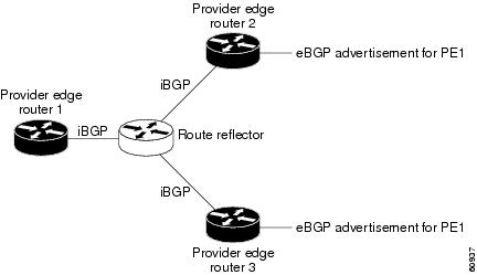
Topology with a Route Reflector
For all equal preference paths to PE1 to be advertised through the route reflector, you must configure each VRF with a different RD. The prefixes received by the route reflector are recognized differently and advertised to PE1.
eBGP Multipath Load Sharing
When a router learns two identical eBGP paths for a prefix from a neighboring autonomous system, it chooses the path with the lower route ID as the best path. This best path is installed in the IP routing table. You can enable eBGP multipath, which installs multiple paths in the IP routing table when the eBGP paths are learned from a neighboring autonomous system, instead of picking one best path.
During packet switching, depending on the switching mode, either per-packet or per-destination load sharing is performed among the multiple paths. The maximum-paths router configuration command controls the number of paths allowed. By default, BGP installs only one path to the IP routing table.
Load Sharing Using Directly Connected Loopback Peering
You use this feature with MPLS VPN Inter-AS and MPLS VPN carrier supporting carrier (CSC) networks to load share traffic between adjacent label switched routers (LSRs) that are connected by multiple links. The LSRs could be a pair of autonomous system boundary routers (ASBRs) or a CSC-PE and a CSC-CE.
Using directly connected loopback peering allows load sharing at the IGP level, so more than one BGP session is not needed between the LSRs. No other label distribution mechanism is needed between the adjacent LSRs than BGP.
Directly connected loopback peering enables load sharing of traffic as follows:
•![]() A BGP session is established, using the loopback addresses of the LSRs.
A BGP session is established, using the loopback addresses of the LSRs.
•![]() MPLS is enabled on the connecting links.
MPLS is enabled on the connecting links.
•![]() Multiple static routes to the loopback address of the adjacent LSR allow IGP load sharing.
Multiple static routes to the loopback address of the adjacent LSR allow IGP load sharing.
•![]() The outgoing label to the loopback address of the adjacent LSR is an implicit null label and is inferred by the LSR.
The outgoing label to the loopback address of the adjacent LSR is an implicit null label and is inferred by the LSR.
•![]() Because IGP load sharing is enabled on the loopback address of the adjacent LSR, any traffic destined to a prefix that is learned over the BGP session (and recurses over the loopback) is load shared.
Because IGP load sharing is enabled on the loopback address of the adjacent LSR, any traffic destined to a prefix that is learned over the BGP session (and recurses over the loopback) is load shared.
How to Configure Load Sharing
This section contains the following procedures:
•![]() Configuring BGP Multipath Load Sharing for eBGP and iBGP (required)
Configuring BGP Multipath Load Sharing for eBGP and iBGP (required)
•![]() Verifying BGP Multipath Load Sharing for eBGP and iBGP (optional)
Verifying BGP Multipath Load Sharing for eBGP and iBGP (optional)
•![]() Configuring eBGP Multipath Load Sharing with MPLS VPN Inter-AS (required)
Configuring eBGP Multipath Load Sharing with MPLS VPN Inter-AS (required)
•![]() Configuring eBGP Multipath Load Sharing with MPLS VPN Carrier Supporting Carrier on the CSC-PE Routers (required)
Configuring eBGP Multipath Load Sharing with MPLS VPN Carrier Supporting Carrier on the CSC-PE Routers (required)
•![]() Configuring Directly Connected Loopback Peering on MPLS VPN Carrier Supporting Carrier (required)
Configuring Directly Connected Loopback Peering on MPLS VPN Carrier Supporting Carrier (required)
Configuring BGP Multipath Load Sharing for eBGP and iBGP
To configure iBGP and eBGP routes for multipath load sharing, perform the following task.
SUMMARY STEPS
1. ![]() enable
enable
2. ![]() configure terminal
configure terminal
3. ![]() router bgp as-number
router bgp as-number
4. ![]() address-family ipv4 [multicast | unicast | vrf vrf-name]
address-family ipv4 [multicast | unicast | vrf vrf-name]
5. ![]() maximum-paths eibgp number-of-paths
maximum-paths eibgp number-of-paths
DETAILED STEPS
Verifying BGP Multipath Load Sharing for eBGP and iBGP
To verify the configuration of iBGP and eBGP routes for multipath load sharing, perform this task.
SUMMARY STEPS
1. ![]() enable
enable
2. ![]() show ip bgp vpnv4 {all | rd route-distinguisher | vrf vrf-name} [rib-failure] [ip-prefix/length [longer-prefixes]] [network-address [mask] [longer-prefixes]] [cidr-only] [community] [community-list] [dampened-paths] [filter-list] [flap-statistics] [inconsistent-as] [neighbors] [paths [line]] [peer-group] [quote-regexp] [regexp] [summary] [labels]
show ip bgp vpnv4 {all | rd route-distinguisher | vrf vrf-name} [rib-failure] [ip-prefix/length [longer-prefixes]] [network-address [mask] [longer-prefixes]] [cidr-only] [community] [community-list] [dampened-paths] [filter-list] [flap-statistics] [inconsistent-as] [neighbors] [paths [line]] [peer-group] [quote-regexp] [regexp] [summary] [labels]
DETAILED STEPS
Configuring eBGP Multipath Load Sharing with MPLS VPN Inter-AS
Perform this task on the ASBRs to configure eBGP Multipath for MPLS VPN interautonomous systems with ASBRs exchanging IPv4 routes and MPLS labels.
SUMMARY STEPS
1. ![]() enable
enable
2. ![]() configure terminal
configure terminal
3. ![]() router bgp as-number
router bgp as-number
4. ![]() neighbor {ip-address | peer-group-name} remote-as as-number
neighbor {ip-address | peer-group-name}
remote-as as-number
5. ![]() address-family ipv4 [multicast | unicast | vrf vrf-name]
address-family ipv4 [multicast | unicast | vrf vrf-name]
6. ![]() maximum paths number-paths
maximum paths number-paths
7. ![]() neighbor {ip-address | peer-group-name} activate
neighbor {ip-address | peer-group-name}
activate
8. ![]() neighbor ip-address send-label
neighbor ip-address send-label
9. ![]() exit-address-family
exit-address-family
10. ![]() end
end
DETAILED STEPS
Configuring eBGP Multipath Load Sharing with MPLS VPN Carrier Supporting Carrier on the CSC-PE Routers
Perform this task to configure eBGP Multipath load sharing on the CSC-PE routers that distribute BGP routes with MPLS labels.
SUMMARY STEPS
1. ![]() enable
enable
2. ![]() configure terminal
configure terminal
3. ![]() router bgp as-number
router bgp as-number
4. ![]() address-family ipv4 [multicast | unicast | vrf vrf-name]
address-family ipv4 [multicast | unicast | vrf vrf-name]
5. ![]() maximum paths number-paths
maximum paths number-paths
6. ![]() neighbor {ip-address | peer-group-name} remote-as as-number
neighbor {ip-address | peer-group-name} remote-as as-number
7. ![]() neighbor {ip-address | peer-group-name} activate
neighbor {ip-address | peer-group-name} activate
8. ![]() neighbor ip-address as-override
neighbor ip-address as-override
9. ![]() neighbor ip-address send-label
neighbor ip-address send-label
10. ![]() exit-address-family
exit-address-family
11. ![]() end
end
DETAILED STEPS
Configuring eBGP Multipath Load Sharing with MPLS VPN Carrier Supporting Carrier on the CSC-CE Routers
Perform this task to configure eBGP Multipath load sharing on the CSC-CE routers.
SUMMARY STEPS
1. ![]() enable
enable
2. ![]() configure terminal
configure terminal
3. ![]() router bgp as-number
router bgp as-number
4. ![]() maximum paths number-paths
maximum paths number-paths
5. ![]() address-family ipv4 [multicast | unicast | vrf vrf-name]
address-family ipv4 [multicast | unicast | vrf vrf-name]
6. ![]() redistribute protocol
redistribute protocol
7. ![]() neighbor {ip-address | peer-group-name} remote-as as-number
neighbor {ip-address | peer-group-name} remote-as as-number
8. ![]() neighbor {ip-address | peer-group-name} activate
neighbor {ip-address | peer-group-name} activate
9. ![]() neighbor
neighbor ip-address send-label
10. ![]() exit-address-family
exit-address-family
11. ![]() end
end
DETAILED STEPS
Configuring Directly Connected Loopback Peering for MPLS VPN Inter-AS using ASBRs to Exchange VPN-IPv4 Addresses
This section describes the following tasks you need to do to configure peering of loopback interfaces of directly connected ASBRs:
•![]() Configuring Loopback Interface Addresses for Directly Connected ASBRs (required)
Configuring Loopback Interface Addresses for Directly Connected ASBRs (required)
•![]() Configuring /32 Static Routes to the eBGP Neighbor Loopback (required)
Configuring /32 Static Routes to the eBGP Neighbor Loopback (required)
•![]() Configuring Forwarding on Connecting Loopback Interfaces (required)
Configuring Forwarding on Connecting Loopback Interfaces (required)
•![]() Configuring an eBGP Session Between the Loopbacks (required)
Configuring an eBGP Session Between the Loopbacks (required)
•![]() Verifying That Load Sharing Occurs Between Loopbacks (optional)
Verifying That Load Sharing Occurs Between Loopbacks (optional)
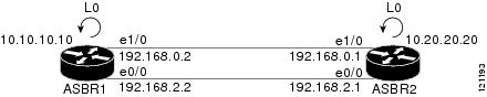
Figure 3 shows the loopback configuration for directly connected ASBR1 and ASBR2. This configuration is used as the example in the tasks that follow.
Figure 3 Loopback Interface Configuration for Directly Connected ASBR1 and ASBR2
Configuring Loopback Interface Addresses for Directly Connected ASBRs
Perform this task to configure loopback interface addresses for directly connected ASBRs.
Note ![]() Loopback addresses need to be configured for each directly connected ASBR. That is, configure a loopback address for ASBR1 and for ASBR2 in the example shown in Figure 3.
Loopback addresses need to be configured for each directly connected ASBR. That is, configure a loopback address for ASBR1 and for ASBR2 in the example shown in Figure 3.
SUMMARY STEPS
1. ![]() enable
enable
2. ![]() configure terminal
configure terminal
3. ![]() interface loopback interface-number
interface loopback interface-number
4. ![]() ip address ip-address mask [secondary]
ip address ip-address mask [secondary]
5. ![]() end
end
DETAILED STEPS
Configuring /32 Static Routes to the eBGP Neighbor Loopback
Perform this task to configure /32 static routes to the eBGP neighbor loopback.
Note ![]() You need to configure /32 static routes on each of the directly connected ASBRs.
You need to configure /32 static routes on each of the directly connected ASBRs.
SUMMARY STEPS
1. ![]() enable
enable
2. ![]() configure terminal
configure terminal
3. ![]() ip route prefix mask {ip-address | interface-type interface-number [ip-address]}
ip route prefix mask {ip-address | interface-type interface-number [ip-address]}
[distance] [name] [permanent] [tag tag]
4. ![]() end
end
DETAILED STEPS
Configuring Forwarding on Connecting Loopback Interfaces
Perform this task to configure forwarding on the connecting loopback interfaces.
This task is required for sessions between loopbacks. In the "Configuring /32 Static Routes to the eBGP Neighbor Loopback" task, Ethernet 1/0 and Ethernet 0/0 are the connecting interfaces.
SUMMARY STEPS
1. ![]() enable
enable
2. ![]() configure terminal
configure terminal
3. ![]() interface type slot/port
interface type slot/port
4. ![]() mpls bgp forwarding
mpls bgp forwarding
5. ![]() exit
exit
6. ![]() Repeat Steps 3 and 4 for another connecting interface (Ethernet 0/0).
Repeat Steps 3 and 4 for another connecting interface (Ethernet 0/0).
7. ![]() end
end
DETAILED STEPS
Configuring an eBGP Session Between the Loopbacks
Perform this task to configure an eBGP session between the loopbacks.
Note ![]() You need to configure an eBGP session between loopbacks on each directly connected ASBR.
You need to configure an eBGP session between loopbacks on each directly connected ASBR.
SUMMARY STEPS
1. ![]() enable
enable
2. ![]() configure terminal
configure terminal
3. ![]() router bgp as-number
router bgp as-number
4. ![]() no bgp default route-target filter
no bgp default route-target filter
5. ![]() neighbor {ip-address | peer-group-name} remote-as as-number
neighbor {ip-address | peer-group-name} remote-as as-number
6. ![]() neighbor {ip-address | peer-group-name} disable-connected-check
neighbor {ip-address | peer-group-name} disable-connected-check
7. ![]() neighbor {ip-address | ipv6-address | peer-group-name} update-source
neighbor {ip-address | ipv6-address | peer-group-name} update-source
interface-type interface-number
8. ![]() address-family vpnv4 [unicast]
address-family vpnv4 [unicast]
9. ![]() neighbor {ip-address | peer-group-name | ipv6-address} activate
neighbor {ip-address | peer-group-name | ipv6-address} activate
10. ![]() neighbor {ip-address | peer-group-name} send-community [both | standard | extended]
neighbor {ip-address | peer-group-name} send-community [both | standard | extended]
11. ![]() end
end
DETAILED STEPS
Verifying That Load Sharing Occurs Between Loopbacks
Perform this task to verify that load sharing occurs between loopbacks. You need to ensure that the MPLS Label Forwarding Information Base (LFIB) entry for the neighbor route lists the available paths and interfaces.
SUMMARY STEPS
1. ![]() enable
enable
2. ![]() show mpls forwarding-table [network {mask | length} | labels label [- label] | interface interface | next-hop address | lsp-tunnel [tunnel-id]] [vrf vrf-name] [detail]
show mpls forwarding-table [network {mask | length} | labels label [- label] | interface interface | next-hop address | lsp-tunnel [tunnel-id]] [vrf vrf-name] [detail]
3. ![]() disable
disable
DETAILED STEPS
Configuring Directly Connected Loopback Peering for MPLS VPN Inter-AS Using ASBRs to Exchange IPv4 Routes and Labels
The following sections describe how to configure peering of loopback interfaces of directly connected ASBRs to achieve load sharing in an interautonomous system network:
•![]() Configuring Loopback Interface Addresses for Directly Connected ASBRs (required)
Configuring Loopback Interface Addresses for Directly Connected ASBRs (required)
•![]() Configuring /32 Static Routes to the eBGP Neighbor Loopback (required)
Configuring /32 Static Routes to the eBGP Neighbor Loopback (required)
•![]() Configuring Forwarding on Connecting Loopback Interfaces (required)
Configuring Forwarding on Connecting Loopback Interfaces (required)
•![]() Configuring an eBGP Session Between the Loopbacks (required)
Configuring an eBGP Session Between the Loopbacks (required)
•![]() Verifying That Load Sharing Occurs Between Loopbacks (optional)
Verifying That Load Sharing Occurs Between Loopbacks (optional)
Figure 4 shows the loopback configuration for directly connected ASBR1 and ASBR2. This configuration is used as the example in the tasks that follow.
Figure 4 Loopback Interface Configuration for Directly Connected ASBR1 and ASBR2
Configuring Loopback Interface Addresses for Directly Connected ASBRs
Perform this task to configure loopback interface addresses.
Note ![]() Loopback addresses need to be configured for each directly connected ASBR. That is, configure a loopback address for ASBR1 and for ASBR2 as in the example shown in Figure 4.
Loopback addresses need to be configured for each directly connected ASBR. That is, configure a loopback address for ASBR1 and for ASBR2 as in the example shown in Figure 4.
SUMMARY STEPS
1. ![]() enable
enable
2. ![]() configure terminal
configure terminal
3. ![]() interface loopback interface-number
interface loopback interface-number
4. ![]() ip address ip-address mask [secondary]
ip address ip-address mask [secondary]
5. ![]() end
end
DETAILED STEPS
Configuring /32 Static Routes to the eBGP Neighbor Loopback
Perform this task to configure /32 static routes to the eBGP neighbor loopback.
Note ![]() You need to configure /32 static routes on each of the directly connected ASBRs.
You need to configure /32 static routes on each of the directly connected ASBRs.
SUMMARY STEPS
1. ![]() enable
enable
2. ![]() configure terminal
configure terminal
3. ![]() ip route prefix mask {ip-address | interface-type interface-number [ip-address]}
ip route prefix mask {ip-address | interface-type interface-number [ip-address]}
[distance] [name] [permanent] [tag tag]
4. ![]() end
end
DETAILED STEPS
Configuring Forwarding on Connecting Loopback Interfaces
Perform this task to configure forwarding on the connecting loopback interfaces.
This task is required for sessions between loopbacks. In the "Configuring /32 Static Routes to the eBGP Neighbor Loopback" task, Ethernet1/0 and Ethernet0/0 are the connecting interfaces.
SUMMARY STEPS
1. ![]() enable
enable
2. ![]() configure terminal
configure terminal
3. ![]() interface type slot/port
interface type slot/port
4. ![]() mpls bgp forwarding
mpls bgp forwarding
5. ![]() exit
exit
6. ![]() Repeat Steps 3 and 4 for another connecting interface (Ethernet 0/0)
Repeat Steps 3 and 4 for another connecting interface (Ethernet 0/0)
7. ![]() end
end
DETAILED STEPS
Configuring an eBGP Session Between the Loopbacks
Perform the following tasks to configure an eBGP session between the loopbacks.
Note ![]() You need to configure an eBGP session between loopbacks on each directly connected ASBR.
You need to configure an eBGP session between loopbacks on each directly connected ASBR.
SUMMARY STEPS
1. ![]() enable
enable
2. ![]() configure terminal
configure terminal
3. ![]() router bgp as-number
router bgp as-number
4. ![]() bgp log-neighbor-changes
bgp log-neighbor-changes
5. ![]() neighbor {ip-address | peer-group-name} remote-as as-number
neighbor {ip-address | peer-group-name} remote-as as-number
6. ![]() neighbor {ip-address | peer-group-name} disable-connected-check
neighbor {ip-address | peer-group-name} disable-connected-check
7. ![]() neighbor {ip-address | ipv6-address | peer-group-name} update-source
neighbor {ip-address | ipv6-address | peer-group-name} update-source
interface-type interface-number
8. ![]() address-family ipv4 [unicast] vrf vrf-name
address-family ipv4 [unicast] vrf vrf-name
9. ![]() neighbor {ip-address | peer-group-name | ipv6-address} activate
neighbor {ip-address | peer-group-name | ipv6-address} activate
10. ![]() neighbor {ip-address | peer-group-name} send-community [both | standard | extended]
neighbor {ip-address | peer-group-name} send-community [both | standard | extended]
11. ![]() end
end
DETAILED STEPS
Verifying That Load Sharing Occurs Between Loopbacks
To verify that load sharing can occur between loopbacks, ensure that the MPLS LFIB entry for the neighbor route lists the available paths and interfaces.
SUMMARY STEPS
1. ![]() enable
enable
2. ![]() show mpls forwarding-table [network {mask | length} | labels label [-label] | interface interface | next-hop address | lsp-tunnel [tunnel-id]] [vrf vrf-name] [detail]
show mpls forwarding-table [network {mask | length} | labels label [-label] | interface interface | next-hop address | lsp-tunnel [tunnel-id]] [vrf vrf-name] [detail]
3. ![]() disable
disable
DETAILED STEPS
Configuring Directly Connected Loopback Peering on MPLS VPN Carrier Supporting Carrier
The following sections explain how to load balance CSC traffic by peering loopback interfaces of directly connected CSC-PE and CSC-CE routers:
•![]() Configuring Loopback Interface Addresses on CSC-PE Routers (required)
Configuring Loopback Interface Addresses on CSC-PE Routers (required)
•![]() Configuring Loopback Interface Addresses for CSC-CE Routers (required)
Configuring Loopback Interface Addresses for CSC-CE Routers (required)
•![]() Configuring /32 Static Routes to the eBGP Neighbor Loopback on the CSC-PE Router (required)
Configuring /32 Static Routes to the eBGP Neighbor Loopback on the CSC-PE Router (required)
•![]() Configuring /32 Static Routes to the eBGP Neighbor Loopback on the CSC-CE Router (required)
Configuring /32 Static Routes to the eBGP Neighbor Loopback on the CSC-CE Router (required)
•![]() Configuring Forwarding on CSC-PE Interfaces That Connect to the CSC-CE Loopback (required)
Configuring Forwarding on CSC-PE Interfaces That Connect to the CSC-CE Loopback (required)
•![]() Configuring Forwarding on CSC-CE Interfaces That Connect to the CSC-PE Loopback (required)
Configuring Forwarding on CSC-CE Interfaces That Connect to the CSC-PE Loopback (required)
•![]() Configuring an eBGP Session Between the CSC-PE Router and the CSC-CE Loopback (required)
Configuring an eBGP Session Between the CSC-PE Router and the CSC-CE Loopback (required)
•![]() Configuring an eBGP Session Between the CSC-CE Router and the CSC-PE Loopback (required)
Configuring an eBGP Session Between the CSC-CE Router and the CSC-PE Loopback (required)
•![]() Verifying That Load Sharing Occurs Between Loopbacks (optional)
Verifying That Load Sharing Occurs Between Loopbacks (optional)
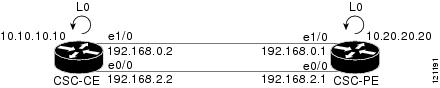
Figure 5 shows the loopback configuration for directly connected CSC-PE and CSC-CE routers. This configuration is used as the example in the tasks that follow.
Figure 5 Loopback Interface Configuration for Directly Connected CSC-PE and CSC-CE Routers
Configuring Loopback Interface Addresses on CSC-PE Routers
Perform this task to configure loopback interface addresses on the CSC-PE router.
Note ![]() Configuration of a loopback interface address on the CSC-PE router requires the enabling of a VRF. The CSC-CE router loopback interface does not require the enabling a of VRF.
Configuration of a loopback interface address on the CSC-PE router requires the enabling of a VRF. The CSC-CE router loopback interface does not require the enabling a of VRF.
SUMMARY STEPS
1. ![]() enable
enable
2. ![]() configure terminal
configure terminal
3. ![]() interface loopback interface-number
interface loopback interface-number
4. ![]() ip vrf forwarding vrf-name
ip vrf forwarding vrf-name
5. ![]() ip address ip-address mask [secondary]
ip address ip-address mask [secondary]
6. ![]() end
end
DETAILED STEPS
Configuring Loopback Interface Addresses for CSC-CE Routers
Perform this task to configure loopback interface addresses for CSC-CE routers.
SUMMARY STEPS
1. ![]() enable
enable
2. ![]() configure terminal
configure terminal
3. ![]() interface loopback interface-number
interface loopback interface-number
4. ![]() ip address ip-address mask [secondary]
ip address ip-address mask [secondary]
5. ![]() end
end
DETAILED STEPS
Configuring /32 Static Routes to the eBGP Neighbor Loopback on the CSC-PE Router
Perform the following task to configure /32 static routes to the eBGP neighbor loopback on the CSC-PE router.
SUMMARY STEPS
1. ![]() enable
enable
2. ![]() configure terminal
configure terminal
3. ![]() ip route vrf vrf-name prefix mask {ip-address | interface-type interface-number [ip-address]}
ip route vrf vrf-name prefix mask {ip-address | interface-type interface-number [ip-address]}
[global] [distance] [name] [permanent] [tag tag]
4. ![]() end
end
DETAILED STEPS
Configuring /32 Static Routes to the eBGP Neighbor Loopback on the CSC-CE Router
Perform the following task to configure /32 static routes to the eBGP neighbor loopback for the CSC-CE router.
SUMMARY STEPS
1. ![]() enable
enable
2. ![]() configure terminal
configure terminal
3. ![]() ip route prefix mask {ip-address | interface-type interface-number [ip-address]}
ip route prefix mask {ip-address | interface-type interface-number [ip-address]}
[distance] [name] [permanent] [tag tag]
4. ![]() end
end
DETAILED STEPS
Configuring Forwarding on CSC-PE Interfaces That Connect to the CSC-CE Loopback
Perform this task to configure forwarding on CSC-PE interfaces that connect to the CSC-CE loopback.
SUMMARY STEPS
1. ![]() enable
enable
2. ![]() configure terminal
configure terminal
3. ![]() interface type slot/port
interface type slot/port
4. ![]() ip vrf forwarding vrf-name
ip vrf forwarding vrf-name
5. ![]() ip address ip-address mask [secondary]
ip address ip-address mask [secondary]
6. ![]() mpls bgp forwarding
mpls bgp forwarding
7. ![]() exit
exit
8. ![]() Repeat Steps 3 through 6 for another connecting interface (Ethernet 0/0).
Repeat Steps 3 through 6 for another connecting interface (Ethernet 0/0).
9. ![]() end
end
DETAILED STEPS—CSC-PE
Configuring Forwarding on CSC-CE Interfaces That Connect to the CSC-PE Loopback
Perform this task to configure forwarding on CSC-CE interfaces that connect to the CSC-PE loopback.
SUMMARY STEPS
1. ![]() enable
enable
2. ![]() configure terminal
configure terminal
3. ![]() interface type slot/port
interface type slot/port
4. ![]() mpls bgp forwarding
mpls bgp forwarding
5. ![]() exit
exit
6. ![]() Repeat Steps 3 and 4 for another connecting interface (Ethernet 0/0).
Repeat Steps 3 and 4 for another connecting interface (Ethernet 0/0).
7. ![]() end
end
DETAILED STEPS
Configuring an eBGP Session Between the CSC-PE Router and the CSC-CE Loopback
Perform this task to configure an eBGP session between the CSC-PE router and the CSC-CE loopback.
SUMMARY STEPS
1. ![]() enable
enable
2. ![]() configure terminal
configure terminal
3. ![]() router bgp as-number
router bgp as-number
4. ![]() bgp log-neighbor-changes
bgp log-neighbor-changes
5. ![]() neighbor {ip-address | peer-group-name} remote-as as-number
neighbor {ip-address | peer-group-name} remote-as as-number
6. ![]() neighbor {ip-address | peer-group-name} disable-connected-check
neighbor {ip-address | peer-group-name} disable-connected-check
7. ![]() neighbor {ip-address | ipv6-address | peer-group-name} update-source
neighbor {ip-address | ipv6-address | peer-group-name} update-source
interface-type interface-number
8. ![]() address-family ipv4 [unicast] vrf vrf-name
address-family ipv4 [unicast] vrf vrf-name
9. ![]() ip vrf forwarding vrf-name
ip vrf forwarding vrf-name
10. ![]() neighbor {ip-address | peer-group-name | ipv6-address} activate
neighbor {ip-address | peer-group-name | ipv6-address} activate
11. ![]() neighbor ip-address send-label
neighbor ip-address send-label
12. ![]() end
end
DETAILED STEPS
Configuring an eBGP Session Between the CSC-CE Router and the CSC-PE Loopback
Perform this task to configure an eBGP session between the CSC-CE router and the CSC-PE loopback.
SUMMARY STEPS
1. ![]() enable
enable
2. ![]() configure terminal
configure terminal
3. ![]() router bgp as-number
router bgp as-number
4. ![]() bgp log-neighbor-changes
bgp log-neighbor-changes
5. ![]() neighbor {ip-address | peer-group-name} remote-as as-number
neighbor {ip-address | peer-group-name} remote-as as-number
6. ![]() neighbor {ip-address | peer-group-name} disable-connected-check
neighbor {ip-address | peer-group-name} disable-connected-check
7. ![]() neighbor {ip-address | ipv6-address | peer-group-name} update-source
neighbor {ip-address | ipv6-address | peer-group-name} update-source
interface-type interface-number
8. ![]() address-family ipv4 [unicast] [vrf vrf-name]
address-family ipv4 [unicast] [vrf vrf-name]
9. ![]() neighbor {ip-address | peer-group-name | ipv6-address} activate
neighbor {ip-address | peer-group-name | ipv6-address} activate
10. ![]() neighbor ip-address send-label
neighbor ip-address send-label
11. ![]() end
end
DETAILED STEPS
Verifying That Load Sharing Occurs Between Loopbacks
To verify that load sharing occurs between loopbacks, ensure that the MPLS LFIB entry for the neighbor route lists the available paths and interfaces.
SUMMARY STEPS
1. ![]() enable
enable
2. ![]() show mpls forwarding-table [vrf vrf-name] [{network {mask | length} | labels label [- label] | interface interface | next-hop address | lsp-tunnel [tunnel-id]}] [detail]
show mpls forwarding-table [vrf vrf-name] [{network {mask | length} | labels label [- label] | interface interface | next-hop address | lsp-tunnel [tunnel-id]}] [detail]
3. ![]() disable
disable
DETAILED STEPS
Configuration Examples for Load Sharing MPLS VPN Traffic
This section contains the following configuration examples for Load Sharing MPLS VPN Traffic:
•![]() Configuring a Router to Select eBGP or iBGP Paths as Multipaths: Example
Configuring a Router to Select eBGP or iBGP Paths as Multipaths: Example
•![]() Configuring a /32 Static Route from an ASBR to the Loopback Address of Another ASBR: Examples
Configuring a /32 Static Route from an ASBR to the Loopback Address of Another ASBR: Examples
•![]() Configuring BGP/MPLS Forwarding on the Interfaces Connecting ASBRs: Example
Configuring BGP/MPLS Forwarding on the Interfaces Connecting ASBRs: Example
•![]() Configuring VPNv4 Sessions on an ASBR: Example
Configuring VPNv4 Sessions on an ASBR: Example
•![]() Verifying VPN NLRI for a Specified Network: Example
Verifying VPN NLRI for a Specified Network: Example
Configuring a Router to Select eBGP or iBGP Paths as Multipaths: Example
The following example configures a router in address family configuration mode to select six eBGP or iBGP paths as multipaths:
Router(config)# router bgp 100
Router(config-router)# address-family ipv4 vrf try
Router(config-router-af)# maximum-paths eibgp 6
Router(config-router-af)# end
Configuring a /32 Static Route from an ASBR to the Loopback Address of Another ASBR: Examples
The following example configures a /32 static route from ASBR1 to the loopback address of ASBR2:
Router# configure terminal
Router(config)# ip route 10.20.20.20 255.255.255 e1/0 168.192.0.1
Router(config)# ip route 10.20.20.20 255.255.255 e0/0 168.192.2.1
The following example configures a /32 static route from ASBR2 to the loopback address of ASBR1:
Router# configure terminal
Router(config)# ip route vrf vpn1 10.10.10.10 255.255.255 e1/0 168.192.0.2
Router(config)# ip route vrf vpn1 10.10.10.10 255.255.255 e0/0 168.192.2.2
Configuring BGP/MPLS Forwarding on the Interfaces Connecting ASBRs: Example
The following example configures BGP/MPLS forwarding on the interfaces connecting ASBR2 with ASBR1:
Router# configure terminal
Router(config)# interface ethernet 1/0
Router(config-if)# ip vrf forwarding vpn1
Router(config-if)# ip address 168.192.0.1 255.255.255.255
Router(config-if)# mpls bgp forwarding
Router(config-if)# exit
Router(config)# interface ethernet 0/0
Router(config-if)# ip vrf forwarding vpn1
Router(config-if)# ip address 168.192.2.1 255.255.255.255
Router(config-if)# mpls bgp forwarding
Router(config-if)# exit
Configuring VPNv4 Sessions on an ASBR: Example
The following example configures VPNv4 sessions on ASBR2:
Router# configure terminal
Router(config)# router bgp 200
Router(config-router)# bgp log-neighbor-changes
Router(config-router)# neighbor 10.10.10.10 remote-as 100
Router(config-router)# neighbor 10.10.10.10 disable-connected-check
Router(config-router)# neighbor 10.10.10.10 update-source Loopback0
!
Router(config-router)# address-family vpnv4
Router(config-router-af)# neighbor 10.10.10.10 activate
Router(config-router-af)# neighbor 10.10.10.10 send-community extended
Router(config-router-af)# end
Verifying VPN NLRI for a Specified Network: Example
If you enter the all keyword with the show ip bgp vpnv4 command, the output displays information about all VPN network layer reachability information (NLRI) for a specified network:
Router# show ip bgp vpnv4 all 10.22.22.0
BGP routing table entry for 10:1:22.22.22.0/24, version 19
Paths:(5 available, best #5)
Multipath: eiBGP
Advertised to non peer-group peers:
10.0.0.2 10.0.0.3 10.0.0.4 10.0.0.5
22
10.0.0.2 (metric 20) from 10.0.0.4 (10.0.0.4)
Origin IGP, metric 0, localpref 100, valid, internal, multipath
Extended Community:0x0:0:0 RT:100:1 0x0:0:0
Originator:10.0.0.2, Cluster list:10.0.0.4
22
10.0.0.2 (metric 20) from 10.0.0.5 (10.0.0.5)
Origin IGP, metric 0, localpref 100, valid, internal, multipath
Extended Community:0x0:0:0 RT:100:1 0x0:0:0
Originator:10.0.0.2, Cluster list:10.0.0.5
22
10.0.0.2 (metric 20) from 10.0.0.2 (10.0.0.2)
Origin IGP, metric 0, localpref 100, valid, internal, multipath
Extended Community:RT:100:1 0x0:0:0
22
10.0.0.2 (metric 20) from 10.0.0.3 (10.0.0.3)
Origin IGP, metric 0, localpref 100, valid, internal, multipath
Extended Community:0x0:0:0 RT:100:1 0x0:0:0
Originator:10.0.0.2, Cluster list:10.0.0.3
22
10.1.1.12 from 10.1.1.12 (10.22.22.12)
Origin IGP, metric 0, localpref 100, valid, external, multipath, best
Extended Community:RT:100:1
Additional References
The following sections provide references related to MPLS VPNs.
Related Documents
|
|
|
|---|---|
MPLS |
|
BGP |
Cisco IOS IP Routing: BGP Configuration Guide, Release 15.0, Configuring BGP |
Standards
|
|
|
|---|---|
No new or modified standards are supported by this feature, and support for existing standards has not been modified by this feature. |
— |
MIBs
RFCs
Technical Assistance
Feature Information for Load Sharing MPLS VPN Traffic
Table 1 lists the release history for this feature.
Not all commands may be available in your Cisco IOS software release. For release information about a specific command, see the command reference documentation.
Use Cisco Feature Navigator to find information about platform support and software image support. Cisco Feature Navigator enables you to determine which Cisco IOS and Catalyst OS software images support a specific software release, feature set, or platform. To access Cisco Feature Navigator, go to http://www.cisco.com/go/cfn. An account on Cisco.com is not required.
Note ![]() Table 1 lists only the Cisco IOS software release that introduced support for a given feature in a given Cisco IOS software release train. Unless noted otherwise, subsequent releases of that Cisco IOS software release train also support that feature.
Table 1 lists only the Cisco IOS software release that introduced support for a given feature in a given Cisco IOS software release train. Unless noted otherwise, subsequent releases of that Cisco IOS software release train also support that feature.
|
|
|
|
|---|---|---|
MPLS VPN—Load Balancing Support for Inter-AS and CSC VPNs |
12.0(29)S |
This feature allows MPLS VPN Inter-AS and MPLS VPN CSC networks to load share traffic between adjacent LSRs that are connected by multiple links. The LSRs can be a pair of ASBRs or a CSC-PE and a CSC-CE. Using directly connected loopback peering allows load sharing at the IGP level, so more than one BGP session is not needed between the LSRs. No other label distribution mechanism is needed between the adjacent LSRs than BGP. The following sections provide information about this feature: • |
BGP Multipath Load Sharing for Both eBGP and iBGP in an MPLS VPN |
12.2(4)T |
This feature allows multihomed autonomous systems and PE routers to be configured to distribute traffic across both external BGP (eBGP) and internal BGP (iBGP) paths. The following sections provide information about this feature: • |
iBGP Multipath Load Sharing |
12.2(2)T |
This feature enables the BGP speaking router to select multiple iBGP paths as the best paths to a destination. The following section provides information about this feature: |
eBGP Multipath |
12.0(27)S |
This feature installs multiple paths in the IP routing table when the eBGP paths are learned from a neighboring Autonomous System (AS), instead of picking one best path. The following sections provide information about this feature: • • |
 Feedback