- MPLS Traffic Engineering and Enhancements
- MPLS Traffic Engineering�Configurable Path Calculation Metric for Tunnels
- MPLS Traffic Engineering�Scalability Enhancements
- MPLS Traffic Engineering�LSP Attributes
- MPLS Traffic Engineering�Verbatim Path Support
- MPLS Traffic Engineering�RSVP Hello State Timer
- MPLS Traffic Engineering Forwarding Adjacency
- MPLS Traffic Engineering�Automatic Bandwidth Adjustment for TE Tunnels
- RSVP Refresh Reduction and Reliable Messaging
MPLS: Traffic Engineering: Path Calculation and Setup Configuration Guide, Cisco IOS XE Release 3S
Bias-Free Language
The documentation set for this product strives to use bias-free language. For the purposes of this documentation set, bias-free is defined as language that does not imply discrimination based on age, disability, gender, racial identity, ethnic identity, sexual orientation, socioeconomic status, and intersectionality. Exceptions may be present in the documentation due to language that is hardcoded in the user interfaces of the product software, language used based on RFP documentation, or language that is used by a referenced third-party product. Learn more about how Cisco is using Inclusive Language.
- Updated:
- February 3, 2009
Chapter: MPLS Traffic Engineering—Configurable Path Calculation Metric for Tunnels
- Finding Feature Information
- Contents
- Prerequisites for MPLS Traffic Engineering—Configurable Path Calculation Metrics for Tunnels
- Restrictions for MPLS Traffic Engineering—Configurable Path Calculation Metrics for Tunnels
- Information About MPLS Traffic Engineering—Configurable Path Calculation Metrics for Tunnels
- How to Configure MPLS Traffic Engineering—Configurable Path Calculation Metrics for Tunnels
- Configuring a Platform to Support Traffic Engineering Tunnels
- Configuring IS-IS for MPLS Traffic Engineering
- Configuring Traffic Engineering Link Metrics
- Configuring an MPLS Traffic Engineering Tunnel
- Configuring the Metric Type for Tunnel Path Calculation
- Verifying the Tunnel Path Metric Configuration
- Configuration Examples for Configuring a Path Calculation Metric for Tunnels
- Additional References
- Feature Information for MPLS Traffic Engineering—Configurable Path Calculation Metrics for Tunnels
MPLS Traffic Engineering—Configurable Path Calculation Metric for Tunnels
The MPLS Traffic Engineering—Configurable Path Calculation Metric for Tunnels feature enables the user to control the metric used in path calculation for traffic engineering (TE) tunnels on a per-tunnel basis. Certain tunnels are used to carry voice traffic, which requires low delay, and other tunnels are used to carry data. A TE link metric can be used to represent link delay and configure tunnels that carry voice traffic for path calculation and configure tunnels that carry data to use the Interior Gateway Protocol (IGP) metric for path calculation.
Finding Feature Information
For the latest feature information and caveats, see the release notes for your platform and software release. To find information about the features documented in this module, and to see a list of the releases in which each feature is supported, see the "Feature Information for MPLS Traffic Engineering—Configurable Path Calculation Metrics for Tunnels" section.
Use Cisco Feature Navigator to find information about platform support and Cisco IOS XE software image support. To access Cisco Feature Navigator, go to http://www.cisco.com/go/cfn. An account on Cisco.com is not required.
Contents
•![]() Prerequisites for MPLS Traffic Engineering—Configurable Path Calculation Metrics for Tunnels
Prerequisites for MPLS Traffic Engineering—Configurable Path Calculation Metrics for Tunnels
•![]() Restrictions for MPLS Traffic Engineering—Configurable Path Calculation Metrics for Tunnels
Restrictions for MPLS Traffic Engineering—Configurable Path Calculation Metrics for Tunnels
•![]() Information About MPLS Traffic Engineering—Configurable Path Calculation Metrics for Tunnels
Information About MPLS Traffic Engineering—Configurable Path Calculation Metrics for Tunnels
•![]() How to Configure MPLS Traffic Engineering—Configurable Path Calculation Metrics for Tunnels
How to Configure MPLS Traffic Engineering—Configurable Path Calculation Metrics for Tunnels
•![]() Configuration Examples for Configuring a Path Calculation Metric for Tunnels
Configuration Examples for Configuring a Path Calculation Metric for Tunnels
•![]() Feature Information for MPLS Traffic Engineering—Configurable Path Calculation Metrics for Tunnels
Feature Information for MPLS Traffic Engineering—Configurable Path Calculation Metrics for Tunnels
Prerequisites for MPLS Traffic Engineering—Configurable Path Calculation Metrics for Tunnels
Before you configure tunnel path calculation metrics, your network must support the following Cisco IOS XE features:
•![]() Multiprotocol Label Switching (MPLS) traffic engineering tunnels
Multiprotocol Label Switching (MPLS) traffic engineering tunnels
•![]() IP Cisco Express Forwarding
IP Cisco Express Forwarding
•![]() Open Shortest Path First (OSPF) or Intermediate System-to-Intermediate System (IS-IS)
Open Shortest Path First (OSPF) or Intermediate System-to-Intermediate System (IS-IS)
Restrictions for MPLS Traffic Engineering—Configurable Path Calculation Metrics for Tunnels
•![]() Unless explicitly configured, the TE link metric for a given link is the IGP link metric. When the TE link metric is used to represent a link property that is different from cost/distance, you must configure every network link that can be used for TE tunnels with a TE link metric that represents that property by using the mpls traffic-eng administrative-weight command. Failure to do so might cause tunnels to use unexpected paths.
Unless explicitly configured, the TE link metric for a given link is the IGP link metric. When the TE link metric is used to represent a link property that is different from cost/distance, you must configure every network link that can be used for TE tunnels with a TE link metric that represents that property by using the mpls traffic-eng administrative-weight command. Failure to do so might cause tunnels to use unexpected paths.
•![]() MPLS traffic engineering supports only a single IGP process/instance. Multiple IGP processes/instances are not supported and MPLS traffic engineering should not be configured in more than one IGP process/instance.
MPLS traffic engineering supports only a single IGP process/instance. Multiple IGP processes/instances are not supported and MPLS traffic engineering should not be configured in more than one IGP process/instance.
Information About MPLS Traffic Engineering—Configurable Path Calculation Metrics for Tunnels
•![]() MPLS Traffic Engineering—Configurable Path Calculation Metrics for Tunnels Overview
MPLS Traffic Engineering—Configurable Path Calculation Metrics for Tunnels Overview
•![]() MPLS Traffic Engineering—Configurable Path Calculation Metrics for Tunnels Benefits
MPLS Traffic Engineering—Configurable Path Calculation Metrics for Tunnels Benefits
MPLS Traffic Engineering—Configurable Path Calculation Metrics for Tunnels Overview
When MPLS TE is configured in a network, the IGP floods two metrics for every link: the normal IGP (OSPF or IS-IS) link metric and a TE link metric. The IGP uses the IGP link metric in the normal way to compute routes for destination networks.
You can specify that the path calculation for a given tunnel be based on either of the following:
•![]() IGP link metrics.
IGP link metrics.
•![]() TE link metrics, which you can configure so that they represent the needs of a particular application. For example, the TE link metrics can be configured to represent link transmission delay.
TE link metrics, which you can configure so that they represent the needs of a particular application. For example, the TE link metrics can be configured to represent link transmission delay.
MPLS Traffic Engineering—Configurable Path Calculation Metrics for Tunnels Benefits
When TE tunnels are used to carry two types of traffic, the Configurable Path Calculation Metric for Tunnels feature allows you to tailor tunnel path selection to the requirements of each type of traffic.
For example, suppose certain tunnels are to carry voice traffic (which requires low delay) and other tunnels are to carry data. In this situation, you can use the TE link metric to represent link delay and do the following:
•![]() Configure tunnels that carry voice to use the TE link metric set to represent link delay for path calculation.
Configure tunnels that carry voice to use the TE link metric set to represent link delay for path calculation.
•![]() Configure tunnels that carry data to use the IGP metric for path calculation.
Configure tunnels that carry data to use the IGP metric for path calculation.
How to Configure MPLS Traffic Engineering—Configurable Path Calculation Metrics for Tunnels
•![]() Configuring a Platform to Support Traffic Engineering Tunnels (required)
Configuring a Platform to Support Traffic Engineering Tunnels (required)
•![]() Configuring the IGP (IS-IS or OSPF) for MPLS Traffic Engineering, page 4 (required)
Configuring the IGP (IS-IS or OSPF) for MPLS Traffic Engineering, page 4 (required)
•![]() Configuring Traffic Engineering Link Metrics (required)
Configuring Traffic Engineering Link Metrics (required)
•![]() Configuring an MPLS Traffic Engineering Tunnel (required)
Configuring an MPLS Traffic Engineering Tunnel (required)
•![]() Configuring the Metric Type for Tunnel Path Calculation (required)
Configuring the Metric Type for Tunnel Path Calculation (required)
•![]() Verifying the Tunnel Path Metric Configuration (optional)
Verifying the Tunnel Path Metric Configuration (optional)
Configuring a Platform to Support Traffic Engineering Tunnels
SUMMARY STEPS
1. ![]() enable
enable
2. ![]() configure terminal
configure terminal
3. ![]() ip cef distributed
ip cef distributed
4. ![]() mpls traffic-eng tunnels
mpls traffic-eng tunnels
5. ![]() exit
exit
DETAILED STEPS
Configuring IS-IS for MPLS Traffic Engineering

Note ![]() MPLS traffic engineering supports only a single IGP process/instance. Multiple IGP processes/instances are not supported and MPLS traffic engineering should not be configured in more than one IGP process/instance.
MPLS traffic engineering supports only a single IGP process/instance. Multiple IGP processes/instances are not supported and MPLS traffic engineering should not be configured in more than one IGP process/instance.
SUMMARY STEPS
1. ![]() enable
enable
2. ![]() configure terminal
configure terminal
3. ![]() router isis
router isis
4. ![]() mpls traffic-eng {level-1 | level-2}
mpls traffic-eng {level-1 | level-2}
5. ![]() mpls traffic-eng {level-1 | level-2}
mpls traffic-eng {level-1 | level-2}
6. ![]() mpls traffic-eng router-id interface-name
mpls traffic-eng router-id interface-name
7. ![]() metric-style wide
metric-style wide
8. ![]() exit
exit
9. ![]() exit
exit
DETAILED STEPS
Configuring OSPF for MPLS Traffic Engineering
Note ![]() MPLS traffic engineering supports only a single IGP process/instance. Multiple IGP processes/instances are not supported and MPLS traffic engineering should not be configured in more than one IGP process/instance.
MPLS traffic engineering supports only a single IGP process/instance. Multiple IGP processes/instances are not supported and MPLS traffic engineering should not be configured in more than one IGP process/instance.
SUMMARY STEPS
1. ![]() enable
enable
2. ![]() configure terminal
configure terminal
3. ![]() router ospf process-id]
router ospf process-id]
4. ![]() mpls traffic-eng area number
mpls traffic-eng area number
5. ![]() mpls traffic-eng router-id interface-name
mpls traffic-eng router-id interface-name
6. ![]() exit
exit
7. ![]() exit
exit
DETAILED STEPS
Configuring Traffic Engineering Link Metrics
Unless explicitly configured, the TE link metric is the IGP link metric.
SUMMARY STEPS
1. ![]() enable
enable
2. ![]() configure terminal
configure terminal
3. ![]() interface type slot/subslot/port[.subinterface-number]
interface type slot/subslot/port[.subinterface-number]
4. ![]() mpls traffic-eng administrative-weight weight
mpls traffic-eng administrative-weight weight
5. ![]() exit
exit
6. ![]() exit
exit
DETAILED STEPS
Configuring an MPLS Traffic Engineering Tunnel
This tunnel has two path setup options: a preferred explicit path and a backup dynamic path.
SUMMARY STEPS
1. ![]() enable
enable
2. ![]() configure terminal
configure terminal
3. ![]() interface tunnel number
interface tunnel number
4. ![]() ip unnumbered type number
ip unnumbered type number
5. ![]() tunnel destination ip-address
tunnel destination ip-address
6. ![]() tunnel mode mpls traffic-eng
tunnel mode mpls traffic-eng
7. ![]() tunnel mpls traffic-eng bandwidth bandwidth
tunnel mpls traffic-eng bandwidth bandwidth
8. ![]() tunnel mpls traffic-eng path-option number {dynamic | explicit {name path-name
tunnel mpls traffic-eng path-option number {dynamic | explicit {name path-name
| id path-number}} [lockdown]
9. ![]() exit
exit
10. ![]() exit
exit
DETAILED STEPS
Configuring the Metric Type for Tunnel Path Calculation
Unless explicitly configured, the TE link metric type is used for tunnel path calculation. Two commands are provided for controlling the metric type to be used: an interface configuration command that specifies the metric type to be used for a particular TE tunnel and a global configuration command that specifies the metric type to be used for TE tunnels for which a metric type has not been specified by the interface configuration command.
Note ![]() If you do not enter either of the path selection metrics commands, the traffic engineering (TE) metric is used.
If you do not enter either of the path selection metrics commands, the traffic engineering (TE) metric is used.
SUMMARY STEPS
1. ![]() enable
enable
2. ![]() configure terminal
configure terminal
3. ![]() interface tunnel number
interface tunnel number
4. ![]() tunnel mpls traffic-eng path-selection metric {igp | te}
tunnel mpls traffic-eng path-selection metric {igp | te}
5. ![]() exit
exit
6. ![]() mpls traffic-eng path-selection metric {igp | te}
mpls traffic-eng path-selection metric {igp | te}
7. ![]() exit
exit
DETAILED STEPS
Verifying the Tunnel Path Metric Configuration
SUMMARY STEPS
1. ![]() enable
enable
2. ![]() show mpls traffic-eng topology
show mpls traffic-eng topology
3. ![]() show mpls traffic-eng tunnels
show mpls traffic-eng tunnels
4. ![]() exit
exit
DETAILED STEPS
Step 1 ![]() enable
enable
Use this command to enable privileged EXEC mode. Enter your password if prompted. For example:
Router> enable
Router#
Step 2 ![]() show mpls traffic-eng topology
show mpls traffic-eng topology
Use the show mpls traffic-eng topology command, which displays TE and IGP metrics for each link, to verify that link metrics have been correctly configured for a network. For example:
Router# show mpls traffic-eng topology
My_System_id: 1440.0000.0044.00 (isis level-1)
IGP Id: 0090.0000.0009.00, MPLS TE Id:192.168.9.9 Router Node (isis level-1)
link[0 ]:Nbr IGP Id: 0090.0000.0009.03, gen:7
frag_id 0, Intf Address:10.0.0.99
TE metric:100, IGP metric:48, attribute_flags:0x0 !!Note TE and IGP metrics
physical_bw: 10000 (kbps), max_reservable_bw_global: 0 (kbps)
max_reservable_bw_sub: 0 (kbps)
.
.
.
link[1 ]:Nbr IGP Id: 0055.0000.0055.00, gen:7
frag_id 0, Intf Address:10.205.0.9, Nbr Intf Address:10.205.0.55
TE metric:120, IGP metric:10, attribute_flags:0x0 !!Note TE and IGP metrics
physical_bw: 155000 (kbps), max_reservable_bw_global: 500000 (kbps)
max_reservable_bw_sub: 0 (kbps)
.
.
.
Step 3 ![]() show mpls traffic-eng tunnels
show mpls traffic-eng tunnels
Use the show mpls traffic-eng tunnels command, which displays the link metric used for tunnel path calculation, to verify that the desired link metrics are being used for each tunnel. For example:
Router# show mpls traffic-eng tunnels
Name: te3640-17-c_t221 (Tunnel22) Destination: 192.168.100.22
Status:
Admin: up Oper: up Path: valid Signalling: connected
path option 1, type dynamic (Basis for Setup, path weight 10)
Config Parameters:
Bandwidth: 400 kps (Global) Priority: 1 1 Affinity: 0x0/0xFFFF
Metric Type: IGP !!Note metric type
AutoRoute: enabled LockDown: disabled Loadshare: 0 bw-based
auto-bw: disabled(0/115) 0 Bandwidth Requested: 0
.
.
.
Name: te3640-17-c_t222 (Tunnel33) Destination: 192.168.100.22
Status:
Admin: up Oper: up Path: valid Signalling: connected
path option 1, type dynamic (Basis for Setup, path weight 10)
Config Parameters:
Bandwidth: 200 kbps (Global) Priority: 1 1 Affinity: 0x0/0xFFFF
Metric Type: TE !!Note metric type
AutoRoute: enabled LockDown: disabled Loadshare: 0 bw-based
auto-bw: disabled(0/115) 0 Bandwidth Requested: 0
.
.
.
Step 4 ![]() exit
exit
Use this command to return to user EXEC mode. For example:
Router# exit
Router>
Configuration Examples for Configuring a Path Calculation Metric for Tunnels
•![]() Example: Configuring Link Type and Metrics for Tunnel Path Selection
Example: Configuring Link Type and Metrics for Tunnel Path Selection
Example: Configuring Link Type and Metrics for Tunnel Path Selection
The section illustrates how to configure the link metric type to be used for tunnel path selection, and how to configure the link metrics themselves. The configuration commands included focus on specifying the metric type for path calculation and assigning metrics to links. Additional commands are required to fully configure the example scenario: for example, the IGP commands for traffic engineering and the link interface commands for enabling traffic engineering and specifying available bandwidth.
The examples in this section support the simple network technology shown in Figure 1.
Figure 1 Network Topology
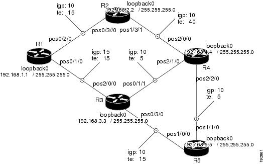
In Figure 1:
•![]() Tunnel1 and Tunnel2 run from R1 (headend) to R4 (tailend).
Tunnel1 and Tunnel2 run from R1 (headend) to R4 (tailend).
•![]() Tunnel3 runs from R1 to R5.
Tunnel3 runs from R1 to R5.
•![]() Path calculation for Tunnel1 and Tunnel3 should use a metric that represents link delay because these tunnels carry voice traffic.
Path calculation for Tunnel1 and Tunnel3 should use a metric that represents link delay because these tunnels carry voice traffic.
•![]() Path calculation for Tunnel2 should use IGP metrics because MPLS TE carries data traffic with no delay requirement.
Path calculation for Tunnel2 should use IGP metrics because MPLS TE carries data traffic with no delay requirement.
Configuration fragments follow for each of the routers that illustrate the configuration relating to link metrics and their use in tunnel path calculation. TE metrics that represent link delay must be configured for the network links on each of the routers, and the three tunnels must be configured on R1.
These configuration fragments force Tunnel1 to take path R1-R3-R4, Tunnel2 to take path R1-R2-R4, and Tunnel3 to take path R1-R3-R4-R5 (assuming the links have sufficient bandwidth to accommodate the tunnels).
R1 Configuration
The following example shows how to configure the tunnel headend (R1) for Tunnel1, Tunnel2, and Tunnel3 in Figure 1:
interface pos0/1/0
mpls traffic-eng administrative-weight 15 !TE metric different from IGP metric
interface pos0/2/0
mpls traffic-eng administrative-weight 15 !TE metric different from IGP metric
interface Tunnel1 !Tunnel1 uses TE metric (default)
!for path selection
ip unnumbered loopback0
tunnel destination 192.168.4.4 255.255.255.0
tunnel mode mpls traffic-eng
tunnel mpls traffic-eng bandwidth 1000
tunnel mpls traffic-eng path-option 1 dynamic
interface Tunnel2 !Tunnel2 uses IGP metric
!for path selection
ip unnumbered loopback0
tunnel destination 192.168.4.4 255.255.255.0
tunnel mode mpls traffic-eng
tunnel mpls traffic-eng bandwidth 1000
tunnel mpls traffic-eng path-option 1 dynamic
tunnel mpls traffic-eng path-selection-metric igp !Use IGP cost for path selection.
interface Tunnel3 !Tunnel3 uses TE metric (default)
!for path selection
ip unnumbered loopback0
tunnel destination 192.168.5.5 255.255.255.0
tunnel mode mpls traffic-eng
tunnel mpls traffic-eng bandwidth 1000
tunnel mpls traffic-eng path-option 1 dynamic
R2 Configuration
The following example shows how to configure R2 in Figure 1:
interface pos0/3/0
mpls traffic-eng administrative-weight 15 !TE metric different from IGP metric
interface pos1/3/1
mpls traffic-eng administrative-weight 40 !TE metric different from IGP metric
R3 Configuration
The following example shows how to configure R3 in Figure 1:
interface pos2/0/0
mpls traffic-eng administrative-weight 15 !TE metric different from IGP metric
interface pos0/3/0
mpls traffic-eng administrative-weight 15 !TE metric different from IGP metric
interface pos0/1/1
mpls traffic-eng administrative-weight 5 !TE metric different from IGP metric
R4 Configuration
The following example shows how to configure R4 in Figure 1:
interface pos2/0/0
mpls traffic-eng administrative-weight 15 !TE metric different from IGP metric
interface pos2/1/0
mpls traffic-eng administrative-weight 15 !TE metric different from IGP metric
interface pos2/2/0
mpls traffic-eng administrative-weight 5 !TE metric different from IGP metric
R5 Configuration
The following example shows how to configure R5 in Figure 1:
interface pos1/0/0
mpls traffic-eng administrative-weight 15 !TE metric different from IGP metric
interface pos1/1/0
mpls traffic-eng administrative-weight 5 !TE metric different from IGP metric
Additional References
Related Documents
|
|
|
|---|---|
Cisco IOS commands |
|
Configuration tasks for IS-IS and OSPF |
|
IS-IS and OSPF commands |
|
Configuration tasks for MPLS and MPLS TE |
Cisco IOS XE Multiprotocol Label Switching Configuration Guide |
MPLS TE commands |
|
Configuration tasks for tunnels |
• • |
Tunnel configuration commands |
• • |
Standards
|
|
|
|---|---|
No new or modified standards are supported by this feature, and support for existing standards has not been modified by this feature. |
- |
MIBs
RFCs
|
|
|
|---|---|
No new or modified RFCs are supported by this feature, and support for existing RFCs has not been modified. |
- |
Technical Assistance
Feature Information for MPLS Traffic Engineering—Configurable Path Calculation Metrics for Tunnels
Table 1 lists the features in this module and provides links to specific configuration information
Use Cisco Feature Navigator to find information about platform support and software image support. Cisco Feature Navigator enables you to determine which software images support a specific software release, feature set, or platform. To access Cisco Feature Navigator, go to http://www.cisco.com/go/cfn. An account on Cisco.com is not required.
Note ![]() Table 1 lists only the software release that introduced support for a given feature in a given software release train. Unless noted otherwise, subsequent releases of that software release train also support that feature.
Table 1 lists only the software release that introduced support for a given feature in a given software release train. Unless noted otherwise, subsequent releases of that software release train also support that feature.
|
|
|
|
|---|---|---|
MPLS Traffic Engineering—Configurable Path Calculation Metric for Tunnels |
Cisco IOS XE Release 2.3 |
The MPLS Traffic Engineering—Configurable Path Calculation Metric for Tunnels feature enables the user to control the metric used in path calculation for traffic engineering (TE) tunnels on a per-tunnel basis. Certain tunnels are used to carry voice traffic, which requires low delay, and other tunnels are used to carry data. A TE link metric can be used to represent link delay and configure tunnels that carry voice traffic for path calculation and configure tunnels that carry data to use the Interior Gateway Protocol (IGP) metric for path calculation. In Cisco IOS XE Release 12.3, this feature was introduced on the Cisco ASR 1000 Series Aggregation Services Routers. The following sections provide information about this feature: • • • • |
• • • • The following commands were introduced or modified: mpls traffic-eng path-selection metric, tunnel mpls traffic-eng path-selection metric. |
 Feedback