- SSO Overview
- Redundancy Modes
- Route Processor Synchronization
- Switchover Operation
- SSO-Aware Protocols and Applications
- Enhanced SNMP Support for High Availability
- SNMP for Stateful Switchover Overview
- SNMP network management with SSO functionality ensures an uninterrupted management interface to the end user. The network administrator can differentiate a switchover from a system restart based on the notification type (for example, ciscoRFSwactNotif for switchover and coldStart or warmStart for system restarts). Uninterrupted service also includes synchronizing the SNMP configuration and data from core MIBs such as IF-MIB and ENTITY-MIB to the standby RP.Network Management for SSO
- Uninterrupted Service Using SSO
- Communication with the NMS
- SSO MIB Support
- CISCO-RF-MIB Modifications for SSO Support
Configuring Stateful Switchover
The Stateful Switchover (SSO) feature works with Nonstop Forwarding (NSF) in Cisco software to minimize the amount of time a network is unavailable to its users following a switchover. The primary objective of SSO is to improve the availability of networks constructed with Cisco routers. SSO performs the following functions:
•![]() Maintains stateful protocol and application information to retain user session information during a switchover.
Maintains stateful protocol and application information to retain user session information during a switchover.
•![]() Enables line cards to continue to forward network traffic with no loss of sessions, providing improved network availability.
Enables line cards to continue to forward network traffic with no loss of sessions, providing improved network availability.
•![]() Provides a faster switchover relative to high system availability.
Provides a faster switchover relative to high system availability.
Finding Feature Information
Your software release may not support all the features documented in this module. For the latest feature information and caveats, see the release notes for your platform and software release. To find information about the features documented in this module, and to see a list of the releases in which each feature is supported, see the "Feature Information for Stateful Switchover" section.
Use Cisco Feature Navigator to find information about platform support and Cisco software image support. To access Cisco Feature Navigator, go to http://www.cisco.com/go/cfn. An account on Cisco.com is not required.
Contents
•![]() Prerequisites for Stateful Switchover
Prerequisites for Stateful Switchover
•![]() Restrictions for Stateful Switchover
Restrictions for Stateful Switchover
•![]() Information About Stateful Switchover
Information About Stateful Switchover
•![]() How to Configure Stateful Switchover
How to Configure Stateful Switchover
•![]() Configuration Examples for Configuring Stateful Switchover, page 28
Configuration Examples for Configuring Stateful Switchover, page 28
•![]() Feature Information for Stateful Switchover
Feature Information for Stateful Switchover
Prerequisites for Stateful Switchover
•![]() SNMP for Stateful Switchover Prerequisites
SNMP for Stateful Switchover Prerequisites
General Prerequisites
•![]() For hardware-redundant platforms, two Route Processors (RPs) must be installed in the chassis, each running the same version or a compatible version of the Cisco software.
For hardware-redundant platforms, two Route Processors (RPs) must be installed in the chassis, each running the same version or a compatible version of the Cisco software.
•![]() Before copying a file to flash memory, be sure that ample space is available in flash memory. Compare the size of the file you are copying to the amount of available flash memory shown. If the space available is less than the space required by the file you will copy, the copy process will not continue and an error message similar to the following will be displayed:
Before copying a file to flash memory, be sure that ample space is available in flash memory. Compare the size of the file you are copying to the amount of available flash memory shown. If the space available is less than the space required by the file you will copy, the copy process will not continue and an error message similar to the following will be displayed:
%Error copying tftp://image@server/tftpboot/filelocation/imagename (Not enough space
on device).
•![]() Distributed Cisco Express Forwarding must be enabled on any networking device configured to run SSO.
Distributed Cisco Express Forwarding must be enabled on any networking device configured to run SSO.
•![]() For Nonstop Forwarding (NSF) support, neighbor routers must be running NSF-enabled images, though SSO need not be configured on the neighbor device.
For Nonstop Forwarding (NSF) support, neighbor routers must be running NSF-enabled images, though SSO need not be configured on the neighbor device.
SNMP for Stateful Switchover Prerequisites
•![]() The router must be in SSO mode.
The router must be in SSO mode.
•![]() SNMP must be configured. See the "Configuring SNMP Support" module of Cisco IOS XE Network Management Configuration Guide for configuration information. There are no configuration tasks for SNMP for SSO.
SNMP must be configured. See the "Configuring SNMP Support" module of Cisco IOS XE Network Management Configuration Guide for configuration information. There are no configuration tasks for SNMP for SSO.
Restrictions for Stateful Switchover
•![]() Configuration Mode Restrictions
Configuration Mode Restrictions
•![]() Switchover Process Restrictions
Switchover Process Restrictions
•![]() Cisco IOS XE Release 2.2 Restrictions
Cisco IOS XE Release 2.2 Restrictions
•![]() Cisco ASR 1000 Series Aggregation Services Routers Restrictions
Cisco ASR 1000 Series Aggregation Services Routers Restrictions
•![]() SNMP for Stateful Switchover Restrictions
SNMP for Stateful Switchover Restrictions
General Restrictions
•![]() Both RPs must run the same Cisco software image. If the RPs are operating different Cisco software images, the system reverts to RPR mode even if SSO is configured.
Both RPs must run the same Cisco software image. If the RPs are operating different Cisco software images, the system reverts to RPR mode even if SSO is configured.
•![]() Configuration changes made through SNMP may not be automatically configured on the standby RP after a switchover occurs.
Configuration changes made through SNMP may not be automatically configured on the standby RP after a switchover occurs.
•![]() Load sharing between dual processors is not supported.
Load sharing between dual processors is not supported.
•![]() The Hot Standby Routing Protocol (HSRP) is not supported with Cisco Nonstop Forwarding with Stateful Switchover. Do not use HSRP with Cisco Nonstop Forwarding with Stateful Switchover.
The Hot Standby Routing Protocol (HSRP) is not supported with Cisco Nonstop Forwarding with Stateful Switchover. Do not use HSRP with Cisco Nonstop Forwarding with Stateful Switchover.
•![]() Enhanced Object Tracking (EOT) is not stateful switchover-aware and cannot be used with HSRP, Virtual Router Redundancy Protocol (VRRP), or Gateway Load Balancing Protocol (GLBP) in SSO mode.
Enhanced Object Tracking (EOT) is not stateful switchover-aware and cannot be used with HSRP, Virtual Router Redundancy Protocol (VRRP), or Gateway Load Balancing Protocol (GLBP) in SSO mode.
•![]() Multicast is not SSO-aware and restarts after switchover; therefore, multicast tables and data structures are cleared upon switchover.
Multicast is not SSO-aware and restarts after switchover; therefore, multicast tables and data structures are cleared upon switchover.
Configuration Mode Restrictions
•![]() The configuration registers on both RPs must be set the same for the networking device to behave the same when either RP is rebooted.
The configuration registers on both RPs must be set the same for the networking device to behave the same when either RP is rebooted.
•![]() During the startup (bulk) synchronization, configuration changes are not allowed. Before making any configuration changes, wait for a message similar to the following:
During the startup (bulk) synchronization, configuration changes are not allowed. Before making any configuration changes, wait for a message similar to the following:
Dec 3 04:05:55.350: %HA_CONFIG_SYNC-6-BULK_CFGSYNC_SUCCEED: Bulk Sync succeeded
Dec 3 04:05:55.418: %RF-5-RF_TERMINAL_STATE: Terminal state reached for (SSO)
Switchover Process Restrictions
•![]() If the router is configured for SSO mode, and the active RP fails before the standby is ready to switch over, the router will recover through a full system reset.
If the router is configured for SSO mode, and the active RP fails before the standby is ready to switch over, the router will recover through a full system reset.
ATM Restrictions
•![]() Label-controlled ATM (LC-ATM) functionality does not co-exist with SSO in this release.
Label-controlled ATM (LC-ATM) functionality does not co-exist with SSO in this release.
•![]() The ATM line protocol does not support stateful switchover capability for the following features:
The ATM line protocol does not support stateful switchover capability for the following features:
–![]() SVCs
SVCs
–![]() Switched virtual paths (SVPs)
Switched virtual paths (SVPs)
–![]() Tagged virtual circuits (TVCs)
Tagged virtual circuits (TVCs)
–![]() Point-to-multipoint SVC
Point-to-multipoint SVC
–![]() Integrated Local Management Interface (ILMI)
Integrated Local Management Interface (ILMI)
–![]() Signaling and Service Specific Connection Oriented Protocol (SSCOP)
Signaling and Service Specific Connection Oriented Protocol (SSCOP)
–![]() ATM Connection Manager, PVC discovery, ATM applications
ATM Connection Manager, PVC discovery, ATM applications
–![]() Backward or version compatibility
Backward or version compatibility
–![]() Statistics and accounting
Statistics and accounting
–![]() Zero ATM cell loss
Zero ATM cell loss
Cisco IOS XE Release 2.2 Restrictions
•![]() SSO is not supported for IP sessions or traffic class sessions.
SSO is not supported for IP sessions or traffic class sessions.
•![]() SSO is not supported for any features on IP sessions or traffic class sessions.
SSO is not supported for any features on IP sessions or traffic class sessions.
•![]() SSO is not supported for the following features for PPP sessions: PBHK; L4RD; and Traffic class.
SSO is not supported for the following features for PPP sessions: PBHK; L4RD; and Traffic class.
•![]() IP sessions are only present on the active router and are not checkpointed to the standby router. Therefore, upon switchover, sessions have to be reestablished and the subscriber must reselect services.
IP sessions are only present on the active router and are not checkpointed to the standby router. Therefore, upon switchover, sessions have to be reestablished and the subscriber must reselect services.
Cisco ASR 1000 Series Aggregation Services Routers Restrictions
•![]() Only RPR and SSO are supported on the Cisco ASR 1000 Series Routers.
Only RPR and SSO are supported on the Cisco ASR 1000 Series Routers.
•![]() RPR and SSO can be used on the Cisco ASR 1000 Series Router to enable a second Cisco software process on a single RP. This configuration option is only available on a Cisco ASR 1002 Router and Cisco ASR 1004 Router. On all other Cisco ASR 1000 Series Routers, the second Cisco software process can run on the standby RP only.
RPR and SSO can be used on the Cisco ASR 1000 Series Router to enable a second Cisco software process on a single RP. This configuration option is only available on a Cisco ASR 1002 Router and Cisco ASR 1004 Router. On all other Cisco ASR 1000 Series Routers, the second Cisco software process can run on the standby RP only.
•![]() A second software process can only be enabled using RPR or SSO if the RP is using 4 GB of DRAM. Use the show version command output to display the amount of DRAM configured on the router.
A second software process can only be enabled using RPR or SSO if the RP is using 4 GB of DRAM. Use the show version command output to display the amount of DRAM configured on the router.
SNMP for Stateful Switchover Restrictions
•![]() Statistics and counter values will not be synchronized from the active to the standby RP.
Statistics and counter values will not be synchronized from the active to the standby RP.
•![]() Only the MIBs listed in the "SSO MIB Support" section are synchronized between the active and the standby RPs.
Only the MIBs listed in the "SSO MIB Support" section are synchronized between the active and the standby RPs.
•![]() SNMP requests can fail during the switchover process, that is, while the standby RP is taking over as the active RP. Data in the unsynchronized MIBs may be out of synchronization, and the information in these MIBs can be lost on a switchover.
SNMP requests can fail during the switchover process, that is, while the standby RP is taking over as the active RP. Data in the unsynchronized MIBs may be out of synchronization, and the information in these MIBs can be lost on a switchover.
•![]() Synchronization of SNMP data between RPs is available only when the networking device is operating in SSO mode.
Synchronization of SNMP data between RPs is available only when the networking device is operating in SSO mode.
Information About Stateful Switchover
•![]() Route Processor Synchronization
Route Processor Synchronization
•![]() SSO-Aware Protocols and Applications
SSO-Aware Protocols and Applications
•![]() Enhanced SNMP Support for High Availability
Enhanced SNMP Support for High Availability
SSO Overview
SSO provides protection for network edge devices with dual RPs that represent a single point of failure in the network design, and where an outage might result in loss of service for customers.
In Cisco networking devices that support dual RPs, SSO takes advantage of RP redundancy to increase network availability. The feature establishes one of the RPs as the active processor while the other RP is designated as the standby processor, and then synchronizing critical state information between them. Following an initial synchronization between the two processors, SSO dynamically maintains RP state information between them.
On Cisco ASR 1000 series routers, SSO can also be used to enable a second Cisco software process on the same RP. This second Cisco IOS process acts as a standby process for the active Cisco software process, and also allows certain subpackages to be upgraded without experiencing any router downtime.
A switchover from the active to the standby processor occurs when the active RP fails, is removed from the networking device, or is manually taken down for maintenance.
SSO is used with the Cisco Nonstop Forwarding (NSF) feature. Cisco NSF allows for the forwarding of data packets to continue along known routes while the routing protocol information is being restored following a switchover. With Cisco NSF, peer networking devices do not experience routing flaps, thereby reducing loss of service outages for customers.
Figure 1 illustrates how SSO is typically deployed in service provider networks. In this example, Cisco NSF with SSO is primarily at the access layer (edge) of the service provider network. A fault at this point could result in loss of service for enterprise customers requiring access to the service provider network.
Figure 1 Cisco NSF with SSO Network Deployment: Service Provider Networks
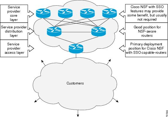
For Cisco NSF protocols that require neighboring devices to participate in Cisco NSF, Cisco NSF-aware software images must be installed on those neighboring distribution layer devices. Additional network availability benefits might be achieved by applying Cisco NSF and SSO features at the core layer of your network; however, consult your network design engineers to evaluate your specific site requirements.
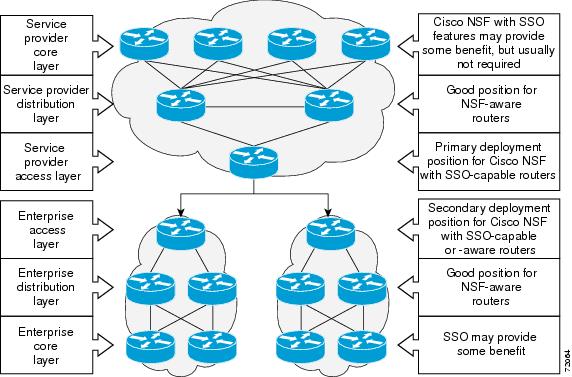
Additional levels of availability may be gained by deploying Cisco NSF with SSO at other points in the network where a single point of failure exists. Figure 2 illustrates an optional deployment strategy that applies Cisco NSF with SSO at the enterprise network access layer. In this example, each access point in the enterprise network represents another single point of failure in the network design. In the event of a switchover or a planned software upgrade, enterprise customer sessions would continue uninterrupted through the network.
Figure 2 Cisco NSF with SSO Network Deployment: Enterprise Networks
Redundancy Modes
•![]() Route Processor Redundancy Mode
Route Processor Redundancy Mode
•![]() Route Processor Redundancy Plus
Route Processor Redundancy Plus
Route Processor Redundancy Mode
Router Processor Redundancy (RPR) allows Cisco software to be booted on the standby processor prior to switchover (a cold boot). In RPR, the standby RP loads a Cisco software image at boot time and initializes itself in standby mode; however, although the startup configuration is synchronized to the standby RP, system changes are not. In the event of a fatal error on the active RP, the system switches to the standby processor, which reinitializes itself as the active processor, reads and parses the startup configuration, reloads all of the line cards, and restarts the system.
Route Processor Redundancy Plus
In RPR+ mode, the standby RP is fully initialized. For RPR+ both the active RP and the standby RP must be running the same software image. The active RP dynamically synchronizes startup and the running configuration changes to the standby RP, meaning that the standby RP need not be reloaded and reinitialized (a hot boot ).
Stateful Switchover Mode
SSO mode provides all the functionality of RPR+ in that the software is fully initialized on the standby RP. In addition, SSO supports synchronization of line card, protocol, and application state information between RPs for supported features and protocols (a hot standby ).
Route Processor Synchronization
In networking devices running SSO, both RPs must be running the same configuration so that the standby RP is always ready to assume control if the active RP fails.
To achieve the benefits of SSO, synchronize the configuration information from the active RP to the standby RP at startup and whenever changes to the active RP configuration occur. This synchronization occurs in two separate phases:
•![]() While the standby RP is booting, the configuration information is synchronized in bulk from the active RP to the standby RP.
While the standby RP is booting, the configuration information is synchronized in bulk from the active RP to the standby RP.
•![]() When configuration or state changes occur, an incremental synchronization is conducted from the active RP to the standby RP.
When configuration or state changes occur, an incremental synchronization is conducted from the active RP to the standby RP.
Bulk Synchronization During Initialization
When a system with SSO is initialized, the active RP performs a chassis discovery (discovery of the number and type of line cards and fabric cards, if available, in the system) and parses the startup configuration file.
The active RP then synchronizes this data to the standby RP and instructs the standby RP to complete its initialization. This method ensures that both RPs contain the same configuration information.
Even though the standby RP is fully initialized, it interacts only with the active RP to receive incremental changes to the configuration files as they occur. Executing CLI commands on the standby RP is not supported.
During system startup, the startup configuration file is copied from the active RP to the standby RP. Any existing startup configuration file on the standby RP is overwritten. The startup configuration is a text file stored in the NVRAM of the RP. It is synchronized whenever you perform the following operations:
•![]() The command copy system:running-config nvram:startup-config is used.
The command copy system:running-config nvram:startup-config is used.
•![]() The command copy running-config startup-config is used.
The command copy running-config startup-config is used.
•![]() The command write memory is used.
The command write memory is used.
•![]() The command copy filename nvram:startup-config is used.
The command copy filename nvram:startup-config is used.
•![]() SNMP SET of MIB variable ccCopyEntry in CISCO_CONFIG_COPY MIB is used.
SNMP SET of MIB variable ccCopyEntry in CISCO_CONFIG_COPY MIB is used.
•![]() System configuration is saved using the reload command.
System configuration is saved using the reload command.
•![]() System configuration is saved following entry of a forced switchover command.
System configuration is saved following entry of a forced switchover command.
Incremental Synchronization
After both RPs are fully initialized, any further changes to the running configuration or active RP states are synchronized to the standby RP as they occur. Active RP states are updated as a result of processing protocol information, external events (such as the interface becoming up or down), or user configuration commands (using Cisco IOS commands or Simple Network Management Protocol [SNMP]) or other internal events.
Changes to the running configuration are synchronized from the active RP to the standby RP. In effect, the command is run on both the active and the standby RP.
Configuration changes caused by an SNMP set operation are synchronized on a case-by-case basis. Only two SNMP configuration set operations are supported:
•![]() shut and no-shut (of an interface)
shut and no-shut (of an interface)
•![]() link up/down trap enable/disable
link up/down trap enable/disable
Routing and forwarding information is synchronized to the standby RP:
•![]() State changes for SSO-aware protocols (ATM, Frame Relay, PPP, High-Level Data Link Control [HDLC]) or applications (SNMP) are synchronized to the standby RP.
State changes for SSO-aware protocols (ATM, Frame Relay, PPP, High-Level Data Link Control [HDLC]) or applications (SNMP) are synchronized to the standby RP.
•![]() Cisco Express Forwarding (CEF) updates to the Forwarding Information Base (FIB) are synchronized to the standby RP.
Cisco Express Forwarding (CEF) updates to the Forwarding Information Base (FIB) are synchronized to the standby RP.
Chassis state changes are synchronized to the standby RP. Changes to the chassis state due to line card insertion or removal are synchronized to the standby RP.
Changes to the line card states are synchronized to the standby RP. Line card state information is initially obtained during bulk synchronization of the standby RP. Following bulk synchronization, line card events, such as whether the interface is up or down, received at the active processor are synchronized to the standby RP.
The various counters and statistics maintained in the active RP are not synchronized because they may change often and because the degree of synchronization they require is substantial. The volume of information associated with statistics makes synchronizing them impractical.
Not synchronizing counters and statistics between RPs may create problems for external network management systems that monitor this information.
Switchover Operation
•![]() Online Removal of the Active RP
Online Removal of the Active RP
Switchover Conditions
An automatic or manual switchover may occur under the following conditions:
•![]() A fault condition that causes the active RP to crash or reboot—automatic switchover
A fault condition that causes the active RP to crash or reboot—automatic switchover
•![]() The active RP is declared dead (not responding)—automatic switchover
The active RP is declared dead (not responding)—automatic switchover
•![]() The command is invoked—manual switchover
The command is invoked—manual switchover
The user can force the switchover from the active RP to the standby RP by using a CLI command. This manual procedure allows for a "graceful" or controlled shutdown of the active RP and switchover to the standby RP. This graceful shutdown allows critical cleanup to occur.

Note ![]() This procedure should not be confused with the graceful shutdown procedure for routing protocols in core routers—they are separate mechanisms.
This procedure should not be confused with the graceful shutdown procedure for routing protocols in core routers—they are separate mechanisms.

Switchover Time
Switchover time is only a few seconds on the Cisco ASR 1000 Series Router. Packets that are switched or routed by the Cisco QuantumFlow Processor (QFP) on the switching fabric card are not impacted by the RP switchover. However, if packets are punted to the RP for further processing, switching and routing will be impacted. The length of time can be due to a number of factors including the time needed for the previously active processor to obtain crash information, load code and microcode, and synchronize configurations between processors and line protocols and Cisco NSF-supported protocols.
The Cisco ASR 1000 Series Router has separate RPs and Forwarding Processor (FP). All transit packets are handles by the FP. Therefore, no transit packet loss occurs during RP switchover (dual RPs) or during IOSD process switchover (single RP).
Online Removal of the Active RP
For Cisco ASR 1000 Series Routers that are configured to use SSO, online removal of the active RP automatically forces a stateful switchover to the standby RP.
Core Dump Operation
In networking devices that support SSO, the newly active primary processor runs the core dump operation after the switchover has taken place. Not having to wait for dump operations effectively decreases the switchover time between processors.
Following the switchover, the newly active RP will wait for a period of time for the core dump to complete before attempting to reload the formerly active RP. The time period is configurable. For example, on some platforms an hour or more may be required for the formerly active RP to perform a coredump, and it might not be site policy to wait that much time before resetting and reloading the formerly active RP. In the event that the core dump does not complete within the time period provided, the standby is reset and reloaded regardless of whether it is still performing a core dump.
The core dump process adds the slot number to the core dump file to identify which processor generated the file content.
Note ![]() Core dumps are generally useful only to your technical support representative. The core dump file, which is a very large binary file, must be transferred using the TFTP, FTP, or remote copy protocol (rcp) server and subsequently interpreted by a Cisco Technical Assistance Center (TAC) representative that has access to source code and detailed memory maps.
Core dumps are generally useful only to your technical support representative. The core dump file, which is a very large binary file, must be transferred using the TFTP, FTP, or remote copy protocol (rcp) server and subsequently interpreted by a Cisco Technical Assistance Center (TAC) representative that has access to source code and detailed memory maps.
SSO-Aware Protocols and Applications
SSO-supported line protocols and applications must be SSO-aware. A feature or protocol is SSO-aware if it maintains, either partially or completely, undisturbed operation through an RP switchover. State information for SSO-aware protocols and applications is synchronized from active to standby to achieve stateful switchover for those protocols and applications.
The dynamically created state of SSO-unaware protocols and applications is lost on switchover and must be reinitialized and restarted on switchover.
SSO-aware applications are either platform-independent, such as in the case of line protocols or platform-dependent (such as line card drivers). Enhancements to the routing protocols (Cisco Express Forwarding, Open Shortest Path First, and Border Gateway Protocol [BGP]) have been made in the SSO feature to prevent loss of peer adjacency through a switchover; these enhancements are platform-independent.
The following protocols and applications are SSO-aware:
•![]() IPv6 Support for Stateful Switchover
IPv6 Support for Stateful Switchover
Line Protocols
SSO-aware line protocols synchronize session state information between the active and standby RPs to keep session information current for a particular interface. In the event of a switchover, session information need not be renegotiated with the peer. During a switchover, SSO-aware protocols also check the line card state to learn if it matches the session state information. SSO-aware protocols use the line card interface to exchange messages with network peers in an effort to maintain network connectivity.
•![]() Frame Relay Stateful Switchover
Frame Relay Stateful Switchover
•![]() PPP and Multilink PPP Stateful Switchover
PPP and Multilink PPP Stateful Switchover
ATM Stateful Switchover
With stateful switchover, ATM dynamic state information is synchronized between the active RP and standby RP. Thus when the active RP fails, the standby RP can take over without spending excessive time relearning the dynamic state information, and forwarding devices can continue to forward packets with only a few seconds of interruption.
Note ![]() ATM SSO is not configurable and runs by default on networking devices configured with ATM and Redundancy Mode SSO.
ATM SSO is not configurable and runs by default on networking devices configured with ATM and Redundancy Mode SSO.
Permanent Virtual Circuits
For ATM to support forwarding during and after switchover, ATM permanent virtual circuits (PVCs) must remain up not only within the networking device, but also within the ATM network.
In an ATM network, all traffic to or from an ATM interface is prefaced with a virtual path identifier (VPI) and virtual channel identifier (VCI). A VPI-VCI pair is considered a single virtual circuit. Each virtual circuit is a private connection to another node on the ATM network. In ATM SSO, the VPI-VCI pair is associated with a virtual circuit descriptor (VCD). ATM SSO uses VCD information in synchronizing VPI-VCI information to the standby RP.
Each virtual circuit is treated as a point-to-point or point-to-multipoint mechanism to another networking device or host and can support bidirectional traffic. On point-to-point subinterfaces, or when static mappings are configured, Inverse Address Resolution Protocol (ARP) need not run. In cases where dynamic address mapping is used, an Inverse ARP protocol exchange determines the protocol address to VPI-VCI mapping for the PVC. This process occurs as soon as the PVC on a multipoint subinterface makes the transition to active. If that process fails for some reason, the remote networking device may drop the Inverse ARP request if it has not yet seen the PVC transition to active. Inverse ARP runs every 60 seconds to relearn the dynamic address mapping information for the active RP.
ATM OAM Managed PVC or SVC Timeout
Operation, Administration, and Maintenance (OAM) F5 loopback cells must be echoed back on receipt by the remote host, thus demonstrating connectivity on the PVC between the router and the remote host. With ATM SSO, OAM loopback cells received on an interface must be echoed within 15 seconds before a PVC or switched virtual circuit (SVC) is declared down. By default, the OAM timeout is set to 10 seconds, followed by at most five retries sent at 1-second intervals. In the worst case, a switchover will begin just before expiration of the 10-second period, meaning that the PVC will go down within 5 seconds on the remote networking device if switchover has not completed within 5 seconds.
Note ![]() Timers at remote ATM networking devices may be configurable, depending on the remote device owner.
Timers at remote ATM networking devices may be configurable, depending on the remote device owner.
Frame Relay Stateful Switchover
With stateful switchover, Frame Relay dynamic state information is synchronized between the active RP and standby RP. Thus when the active RP fails, the standby RP can take over without spending excessive time relearning the dynamic state information, and forwarding devices can continue to forward packets with only a few seconds of interruption (less on some platforms).
Permanent Virtual Circuits
For Frame Relay to support forwarding during and after switchover, Frame Relay PVCs must remain up not only within the networking device, but also within the Frame Relay network.
In many cases the networking devices are connected to a switch, rather than back-to-back to another networking device, and that switch is not running Cisco software. The virtual circuit state is dependent on line state. PVCs are down when the line protocol is down. PVCs are up when the line protocol is up and the PVC status reported by the adjacent switch is active.
On point-to-point subinterfaces, or when static mappings are configured, Inverse ARP need not run. In cases where dynamic address mapping is used, an Inverse ARP protocol exchange determines the protocol address to data-link connection identifier (DLCI) mapping for the PVC. This exchange occurs as soon as the multipoint PVC makes the transition to active. If the exchange fails for some reason, for example, the remote networking device may drop the Inverse ARP request if it has not yet seen the PVC transition to active—any outstanding requests are run off a timer, with a default of 60 seconds.
Keepalive Messages
A crucial factor in maintaining PVCs is the delivery of Local Management Interface (LMI) protocol messages (keepalives) during switchover. This keepalive mechanism provides an exchange of information between the network server and the switch to verify that data is flowing.
If a number of consecutive LMI keepalives messages are lost or in error, the adjacent Frame Relay device declares the line protocol down and all PVCs on that interface are declared down within the Frame Relay network and reported as such to the remote networking device. The speed with which a switchover occurs is crucial to avoid the loss of keepalive messages.
The line protocol state depends on the Frame Relay keepalive configuration. With keepalives disabled, the line protocol is always up as long as the hardware interface is up. With keepalives enabled, LMI protocol messages are exchanged between the networking device and the adjacent Frame Relay switch. The line protocol is declared up after a number of consecutive successful LMI message exchanges.
The line protocol must be up according to both the networking device and the switch. The default number of exchanges to bring up the line protocol is implementation-dependent: Three is suggested by the standards; four is used on a Cisco Frame Relay switch, taking 40 seconds at the default interval of 10 seconds; and two is used on a Cisco networking device acting as a switch or when connected back-to-back. This default number could be extended if the LMI "autosense" feature is being used while the LMI type expected on the switch is determined. The number of exchanges is configurable, although the switch and router may not have the same owner.
The default number of lost messages or errors needed to bring down the line is three (two on a Cisco IOS XE router). By default, if a loss of two messages is detected in 15 to 30 seconds, then a sequence number or LMI type error in the first message from the newly active RP takes the line down.
If a line goes down, consecutive successful LMI protocol exchanges (default of four over 40 seconds on a Cisco Frame Relay switch; default of two over 20 seconds on a Cisco device) will bring the line back up again.
PPP and Multilink PPP Stateful Switchover
With stateful switchover, specific PPP state information is synchronized between the active RP and standby RP. Thus when the active RP fails, the standby RP can take over without spending excessive time renegotiating the setup of a given link. As long as the physical link remains up, forwarding devices can continue to forward packets with only a few seconds of interruption (less on some platforms). Single-link PPP and Multilink PPP (MLP) sessions are maintained during RP switchover for IP connections only.
PPP and MLP support many Layer 3 protocols such as IPX and IP. Only IP links are supported in SSO. Links supporting non IP traffic will momentarily renegotiate and resume forwarding following a switchover. IP links will forward IP traffic without renegotiation.
A key factor in maintaining PPP session integrity during a switchover is the use of keepalive messages. This keepalive mechanism provides an exchange of information between peer interfaces to verify data and link integrity. Depending on the platform and configuration, the time required for switchover to the standby RP might exceed the keepalive timeout period. PPP keepalive messages are started when the physical link is first brought up. By default, keepalive messages are sent at 10-second intervals from one PPP interface to the other PPP peer.
If five consecutive keepalive replies are not received, the PPP link would be taken down on the newly active RP. Caution should be used when changing the keepalive interval duration to any value less than the default setting.
Only in extremely rare circumstances could the RP switchover time exceed the default 50-second keepalive duration. In the unlikely event this time is exceeded, the PPP links would renegotiate with the peers and resume IP traffic forwarding.
Note ![]() PPP and MLP are not configurable and run by default on networking devices configured with SSO.
PPP and MLP are not configurable and run by default on networking devices configured with SSO.
HDLC Stateful Switchover
With stateful switchover, High-Level Data Link Control (HDLC) synchronizes the line protocol state information. Additionally, the periodic timer is restarted for interfaces that use keepalive messages to verify link integrity. Link state information is synchronized between the active RP and standby RP. The line protocols that were up before the switchover remain up afterward as long as the physical interface remains up. Line protocols that were down remain down.
A key factor in maintaining HDLC link integrity during a switchover is the use of keepalive messages. This keepalive mechanism provides an exchange of information between peer interfaces to verify data is flowing. HDLC keepalive messages are started when the physical link is first brought up. By default, keepalive messages are sent at 10-second intervals from one HDLC interface to the other.
HDLC waits at least three keepalive intervals without receiving keepalive messages, sequence number errors, or a combination of both before it declares a line protocol down. If the line protocol is down, SSO cannot support continuous forwarding of user session information in the event of a switchover.
Note ![]() HDLC is not configurable and runs by default on networking devices configured with SSO.
HDLC is not configurable and runs by default on networking devices configured with SSO.
Quality of Service
The modular QoS CLI (MQS)-based QoS feature maintains a database of various objects created by the user, such as those used to specify traffic classes, actions for those classes in traffic policies, and attachments of those policies to different traffic points such as interfaces. With SSO, QoS synchronizes that database between the primary and secondary RP.
IPv6 Support for Stateful Switchover
IPv6 neighbor discovery supports SSO using Cisco Express Forwarding. When switchover occurs, the Cisco Express Forwarding adjacency state, which is checkpointed, is used to reconstruct the neighbor discovery cache.
Line Card Drivers
Platform-specific line card device drivers are bundled with the Cisco software image for SSO and are correct for a specific image, meaning they are designed to be SSO-aware.
Line cards used with the SSO feature periodically generate status events that are forwarded to the active RP. Information includes the line up or down status, and the alarm status. This information helps SSO support bulk synchronization after standby RP initialization and support state reconciliation and verification after a switchover.
Line cards used with the SSO feature also have the following requirements:
•![]() Line cards must not reset during switchover.
Line cards must not reset during switchover.
•![]() Line cards must not be reconfigured.
Line cards must not be reconfigured.
•![]() Subscriber sessions may not be lost.
Subscriber sessions may not be lost.
Note ![]() The standby RP communicates only with the active RP, never with the line cards. This function helps to ensure that the active and standby RP always have the same information.
The standby RP communicates only with the active RP, never with the line cards. This function helps to ensure that the active and standby RP always have the same information.
Routing Protocols and Nonstop Forwarding
Cisco nonstop forwarding (NSF) works with SSO to minimize the amount of time a network is unavailable to its users following a switchover. When a networking device restarts, all routing peers of that device usually detect that the device went down and then came back up. This down-to-up transition results in what is called a "routing flap," which could spread across multiple routing domains. Routing flaps caused by routing restarts create routing instabilities, which are detrimental to the overall network performance. Cisco NSF helps to suppress routing flaps, thus improving network stability.
Cisco NSF allows for the forwarding of data packets to continue along known routes while the routing protocol information is being restored following a switchover. With Cisco NSF, peer networking devices do not experience routing flaps. Data traffic is forwarded through intelligent line cards while the standby RP assumes control from the failed active RP during a switchover. The ability of line cards to remain up through a switchover and to be kept current with the FIB on the active RP is key to Cisco NSF operation.
A key element of Cisco NSF is packet forwarding. In Cisco networking devices, packet forwarding is provided by Cisco Express Forwarding. Cisco Express Forwarding maintains the FIB, and uses the FIB information that was current at the time of the switchover to continue forwarding packets during a switchover. This feature eliminates downtime during the switchover.
Cisco NSF supports the BGP, IS-IS, and OSPF routing protocols. In general, these routing protocols must be SSO-aware to detect a switchover and recover state information (converge) from peer devices. Each protocol depends on Cisco Express Forwarding to continue forwarding packets during switchover while the routing protocols rebuild the Routing Information Base (RIB) tables.
Note ![]() Distributed Cisco Express Forwarding must be enabled in order to run NSF.
Distributed Cisco Express Forwarding must be enabled in order to run NSF.
Network Management
Network management support for SSO is provided through the synchronization of specific SNMP data between the active and standby RPs. From a network management perspective, this functionality helps to provide an uninterrupted management interface to the network administrator.
Note ![]() Synchronization of SNMP data between RPs is available only when the networking device is operating in SSO mode.
Synchronization of SNMP data between RPs is available only when the networking device is operating in SSO mode.
Enhanced SNMP Support for High Availability
•![]() SNMP for Stateful Switchover Overview
SNMP for Stateful Switchover Overview
•![]() Uninterrupted Service Using SSO
Uninterrupted Service Using SSO
•![]() CISCO-RF-MIB Modifications for SSO Support
CISCO-RF-MIB Modifications for SSO Support
SNMP for Stateful Switchover Overview
The SNMP and stateful switchover feature helps to improve the availability of networks made up of Cisco networking devices. Using SSO, a networking device with redundant RPs will continue forwarding traffic, continue operating as a routing protocol peer, and remain manageable under a set of circumstances that ordinarily would cause an interruption in service.
The SSO feature allows one of the processors on the networking device to operate as the active RP, which passes the necessary system, routing, and application state information to the standby RP. Upon switchover, the standby RP quickly assumes the role of active RP. The goal of SNMP network management with SSO functionality is to provide an uninterrupted management interface to the end user during and after a switchover.
SNMP network management with SSO functionality ensures an uninterrupted management interface to the end user. The network administrator can differentiate a switchover from a system restart based on the notification type (for example, ciscoRFSwactNotif for switchover and coldStart or warmStart for system restarts). Uninterrupted service also includes synchronizing the SNMP configuration and data from core MIBs such as IF-MIB and ENTITY-MIB to the standby RP.Network Management for SSO
Network management support for SSO is provided through the synchronization of specific SNMP data between the active and standby RPs. From a network management perspective, this synchronization helps to provide an uninterrupted management interface to the network administrator.
Synchronization of SNMP data between RPs is available only when the networking device is operating in SSO mode.
Uninterrupted Service Using SSO
When a networking device uses SSO, the network management engine of the standby RP should be indistinguishable from the network management engine of the active RP. A network management system (NMS) should not interpret a switchover to mean that a new device has come up.
The sysUpTime MIB object reports the system uptime. To prevent a switchover from being flagged as a restart, this object is synchronized between the active and the standby RPs. As a result, no coldStart or warmStart traps will be generated as a result of the switchover—the ciscoRFSwactNotif notification is used to signal a switchover.
Communication with the NMS
Counters and Statistics
The various counters and statistics maintained in the RP are not synchronized because they may change often and the degree of synchronization they require is substantial. They also are not critical to the system operation. Because of this lack of synchronization, counter objects experience a discontinuity after a switchover. The cRFStatusFailoverTime will be the value of sysUpTime when any one or more of the counters experiences a discontinuity.
Switchover Notification
The ciscoRFSwactNotif notification informs the NMS about a switchover. This notification provides information regarding the unit ID of the originator of the notification, the newly active redundant unit, the sysUptime data, and reason codes for why a switchover has occurred. The NMS can then use the ciscoRFSwactNotif notification to resynchronize the counter statistics values, if necessary. For more information, see the "CISCO-RF-MIB Modifications for SSO Support" section.
Traps
Only notifications generated on the active RP are sent to the notification destination. None of the notifications generated on the standby RP are sent to the notification destination. Furthermore, notifications can be lost if they were generated on the active RP before a switchover. The NMS should be aware of these constraints.
SSO MIB Support
The CISCO-RF-MIB provides configuration control and status for the redundancy facility (RF) subsystem.
MIBs that are not listed in this section do not synchronize data between the redundant units. MIB synchronization for SSO only occurs when the system is in SSO mode.
All the objects in the following MIBs that contain SNMP configuration data are synchronized between the active and standby RPs:
•![]() SNMP-FRAMEWORK-MIB
SNMP-FRAMEWORK-MIB
•![]() SNMP-TARGET-MIB
SNMP-TARGET-MIB
•![]() SNMP-USM-MIB
SNMP-USM-MIB
•![]() SNMP-VACM-MIB
SNMP-VACM-MIB
•![]() SNMPv2-MIB
SNMPv2-MIB
The following core MIBs support SSO:
•![]() ENTITY-MIB—After a switchover, there will be no change in the data reported by the ENTITY-MIB object. This lack of change is result of the entPhysicalIndex and its associated objects being synchronized between the active and the standby RPs. The associated objects of the entPhysicalIndex are as follows:
ENTITY-MIB—After a switchover, there will be no change in the data reported by the ENTITY-MIB object. This lack of change is result of the entPhysicalIndex and its associated objects being synchronized between the active and the standby RPs. The associated objects of the entPhysicalIndex are as follows:
–![]() entPhysicalAlias
entPhysicalAlias
–![]() entPhysicalSerialNum
entPhysicalSerialNum
–![]() entPhysicalAssetID
entPhysicalAssetID
–![]() entLastChangeTime
entLastChangeTime
•![]() IF-MIB—The ifIndex is synchronized between the active and standby RPs, along with the ifNumber, ifTableLastChange, ifAdminStatus, ifLinkUpDownTrapEnable, ifAlias, ifLastChange, and ifStackLastChange objects.
IF-MIB—The ifIndex is synchronized between the active and standby RPs, along with the ifNumber, ifTableLastChange, ifAdminStatus, ifLinkUpDownTrapEnable, ifAlias, ifLastChange, and ifStackLastChange objects.
The following infrastructure MIBs support SSO:
•![]() Community MIB
Community MIB
•![]() Notification MIB
Notification MIB
•![]() Notification log MIB
Notification log MIB
•![]() Field-replaceable unit (FRU) control MIB
Field-replaceable unit (FRU) control MIB
•![]() CISCO-ENHANCED-MEMPOOL-MIB
CISCO-ENHANCED-MEMPOOL-MIB
CISCO-RF-MIB Modifications for SSO Support
•![]() New cRFHistorySwitchOverTable Table in CISCO-RF-MIB for SSO Support
New cRFHistorySwitchOverTable Table in CISCO-RF-MIB for SSO Support
•![]() New Objects in CISCO-RF-MIB for SSO Support
New Objects in CISCO-RF-MIB for SSO Support
New cRFHistorySwitchOverTable Table in CISCO-RF-MIB for SSO Support
The cRFHistorySwitchOverTable tracks the history of switchovers that have occurred since system initialization. New objects that have been added as part of this table are as follows:
•![]() cRFHistoryPrevActiveUnitId—A read-only object that indicates the active RP that went down. The value of this object is the unique ID of the active RP that has gone down. The ID can be the slot ID, the physical or logical entity ID, or a unique ID assigned by the RF.
cRFHistoryPrevActiveUnitId—A read-only object that indicates the active RP that went down. The value of this object is the unique ID of the active RP that has gone down. The ID can be the slot ID, the physical or logical entity ID, or a unique ID assigned by the RF.
•![]() cRFHistoryCurrActiveUnitId—A read-only object that indicates the standby RP that took over as the active RP. The value of this object is the unique ID of the active RP. The ID can be the slot ID, the physical or logical entity ID, or a unique ID assigned by the RF.
cRFHistoryCurrActiveUnitId—A read-only object that indicates the standby RP that took over as the active RP. The value of this object is the unique ID of the active RP. The ID can be the slot ID, the physical or logical entity ID, or a unique ID assigned by the RF.
•![]() cRFHistorySwitchOverReason—A read-only object that indicates the reason for the switchover. The reasons for the switchover from the active RP to the standby RP can be any of the following:
cRFHistorySwitchOverReason—A read-only object that indicates the reason for the switchover. The reasons for the switchover from the active RP to the standby RP can be any of the following:
–![]() unsupported—This feature is unsupported.
unsupported—This feature is unsupported.
–![]() none—No switchover has occurred.
none—No switchover has occurred.
–![]() notKnown—The reason is unknown.
notKnown—The reason is unknown.
–![]() userInitiated—A safe, manual switchover was initiated by the user.
userInitiated—A safe, manual switchover was initiated by the user.
–![]() userForced—A manual switchover was forced by the user. Preconditions, warnings, and safety checks were ignored.
userForced—A manual switchover was forced by the user. Preconditions, warnings, and safety checks were ignored.
–![]() activeUnitFailed—An active RP fault caused an automatic switchover.
activeUnitFailed—An active RP fault caused an automatic switchover.
–![]() activeUnitRemoved—The active RP was removed, which caused an automatic switchover.
activeUnitRemoved—The active RP was removed, which caused an automatic switchover.
•![]() cRFHistorySwactTime—A read-only object that indicates the date and time the switchover occurred. The value of this object is a time stamp with the date and time the switchover occurred.
cRFHistorySwactTime—A read-only object that indicates the date and time the switchover occurred. The value of this object is a time stamp with the date and time the switchover occurred.
New Objects in CISCO-RF-MIB for SSO Support
The object added to the new cRFHistory subgroup are as follows:
•![]() cRFHistoryTableMaxLength—A read-write object that indicates the maximum number of entries permissible in the history table. The value of this object is an integer that is more than 0. A value of 0 results in no history being maintained.
cRFHistoryTableMaxLength—A read-write object that indicates the maximum number of entries permissible in the history table. The value of this object is an integer that is more than 0. A value of 0 results in no history being maintained.
•![]() cRFHistoryColdStarts—A read-only object that indicates the number of system cold starts including the number of system cold starts due to switchover fault and the number of manual restarts.
cRFHistoryColdStarts—A read-only object that indicates the number of system cold starts including the number of system cold starts due to switchover fault and the number of manual restarts.
•![]() cRFHistoryStandByAvailTime—A read-only object that indicates the cumulative time that a standby redundant unit has been available since the last system initialization.
cRFHistoryStandByAvailTime—A read-only object that indicates the cumulative time that a standby redundant unit has been available since the last system initialization.
Two objects related to switchover status have also been added:
•![]() cRFStatusFailoverTime—A read-only object that indicates the sysUpTime value when the primary redundant unit took over as active. The value of this object is 0 until the first switchover.
cRFStatusFailoverTime—A read-only object that indicates the sysUpTime value when the primary redundant unit took over as active. The value of this object is 0 until the first switchover.
cRFStatusPeerStandByEntryTime—A read-only object that indicates the sysUpTime value when the peer redundant unit entered the standbyHot state. The value of this object is 0 on system initialization.
How to Configure Stateful Switchover
•![]() Copying an Image onto an RP(required)
Copying an Image onto an RP(required)
•![]() Setting the Configuration Register and Boot Variable (required)
Setting the Configuration Register and Boot Variable (required)
•![]() Configuring SSO (required)
Configuring SSO (required)
•![]() Configuring Frame Relay SSO for LMI Sequence Numbers Synchronization (optional)
Configuring Frame Relay SSO for LMI Sequence Numbers Synchronization (optional)
•![]() Verifying SSO Configuration (optional)
Verifying SSO Configuration (optional)
•![]() Troubleshooting Stateful Switchover (optional)
Troubleshooting Stateful Switchover (optional)
Copying an Image onto an RP
Note ![]() To copy a consolidated package or subpackages onto active and standby RPs on the Cisco ASR 1000 Series Router, see the Cisco ASR 1000 Series Aggregation Services Routers Software Configuration Guide.
To copy a consolidated package or subpackages onto active and standby RPs on the Cisco ASR 1000 Series Router, see the Cisco ASR 1000 Series Aggregation Services Routers Software Configuration Guide.
SUMMARY STEPS
1. ![]() enable
enable
2. ![]() copy tftp bootflash:image
copy tftp bootflash:image
or
copy tftp harddisk:image
3. ![]() copy tftp stby-bootflash:image
copy tftp stby-bootflash:image
or
copy tftp stby-harddisk:image
4. ![]() exit
exit
DETAILED STEPS
Setting the Configuration Register and Boot Variable
Note ![]() Following the reload, each RP is in its default mode. SSO is the default mode for the Cisco ASR 1000 Series Routers. The default configuration register value is 0x102. However, on a reload, the system is booted with the last saved value.
Following the reload, each RP is in its default mode. SSO is the default mode for the Cisco ASR 1000 Series Routers. The default configuration register value is 0x102. However, on a reload, the system is booted with the last saved value.
SUMMARY STEPS
1. ![]() enable
enable
2. ![]() show version
show version
3. ![]() configure terminal
configure terminal
4. ![]() no boot system flash [flash-fs:][partition-number:][filename]
no boot system flash [flash-fs:][partition-number:][filename]
or
no boot system tftp filename [ip-address]
5. ![]() boot system flash [flash-fs:][partition-number:][filename]
boot system flash [flash-fs:][partition-number:][filename]
or
boot system tftp filename [ip-address]
6. ![]() config-register value
config-register value
7. ![]() exit
exit
8. ![]() copy running-config startup-config
copy running-config startup-config
9. ![]() reload
reload
DETAILED STEPS
Configuring SSO
SUMMARY STEPS
1. ![]() enable
enable
2. ![]() configure terminal
configure terminal
3. ![]() redundancy
redundancy
4. ![]() mode {rpr | sso}
mode {rpr | sso}
5. ![]() end
end
6. ![]() copy running-config startup-config
copy running-config startup-config
DETAILED STEPS
Configuring Frame Relay SSO for LMI Sequence Numbers Synchronization
SUMMARY STEPS
1. ![]() enable
enable
2. ![]() configure terminal
configure terminal
3. ![]() frame-relay redundancy auto-sync lmi-sequence-numbers
frame-relay redundancy auto-sync lmi-sequence-numbers
DETAILED STEPS
Verifying SSO Configuration
SUMMARY STEPS
1. ![]() enable
enable
2. ![]() show redundancy [clients | counters | history | switchover history | states]
show redundancy [clients | counters | history | switchover history | states]
3. ![]() show redundancy states
show redundancy states
DETAILED STEPS
Troubleshooting Stateful Switchover
•![]() Resolving Possible SSO Problem Situations
Resolving Possible SSO Problem Situations
•![]() Troubleshooting SNMP for Stateful Switchover
Troubleshooting SNMP for Stateful Switchover
Resolving Possible SSO Problem Situations
Step 1 ![]() The standby RP was reset, but there are no messages describing what happened—To display a log of SSO events and clues as to why a switchover or other event occurred, enter the show redundancy history command on the newly active RP:
The standby RP was reset, but there are no messages describing what happened—To display a log of SSO events and clues as to why a switchover or other event occurred, enter the show redundancy history command on the newly active RP:
Router# show redundancy history
Step 2 ![]() The show redundancy states command shows an operating mode that is different than what is configured on the networking device—On certain platforms the output of the show redundancy states command displays the actual operating redundancy mode running on the device, and not the configured mode as set by the platform. The operating mode of the system can change depending on system events. For example, SSO requires that both RPs on the networking device be running the same software image; if the images are different, the device will not operate in SSO mode, regardless of its configuration.
The show redundancy states command shows an operating mode that is different than what is configured on the networking device—On certain platforms the output of the show redundancy states command displays the actual operating redundancy mode running on the device, and not the configured mode as set by the platform. The operating mode of the system can change depending on system events. For example, SSO requires that both RPs on the networking device be running the same software image; if the images are different, the device will not operate in SSO mode, regardless of its configuration.
During the upgrade process, different images will be loaded on the RPs for a short period of time. If a switchover occurs during this time, the device will recover in RPR mode.
Step 3 ![]() Reloading the device disrupts SSO operation—The SSO feature introduces a number of commands, including commands to manually cause a switchover. The reload command is not an SSO command. This command causes a full reload of the box, removing all table entries, resetting all line cards, and thereby interrupting network traffic forwarding. To avoid reloading the box unintentionally, use the redundancy force-switchover command.
Reloading the device disrupts SSO operation—The SSO feature introduces a number of commands, including commands to manually cause a switchover. The reload command is not an SSO command. This command causes a full reload of the box, removing all table entries, resetting all line cards, and thereby interrupting network traffic forwarding. To avoid reloading the box unintentionally, use the redundancy force-switchover command.
Step 4 ![]() During a software upgrade, the networking device appears to be in a mode other than SSO—During the software upgrade process, the show redundancy command indicates that the device is running in a mode other than SSO.
During a software upgrade, the networking device appears to be in a mode other than SSO—During the software upgrade process, the show redundancy command indicates that the device is running in a mode other than SSO.
This is normal behavior. Until the ISSU procedure is complete, each RP will be running a different software version. While the RPs are running different software versions, the mode will change to RPR. The device will change to SSO mode once the upgrade has completed.
Step 5 ![]() You can enter ROM monitor mode by restarting the router and then pressing the Break key or issuing a send break command from a telnet session during the first 60 seconds of startup.The send break function can be useful for experienced users or for users under the direction of a Cisco Technical Assistance Center (TAC) representative to recover from certain system problems or to evaluate the cause of system problems.
You can enter ROM monitor mode by restarting the router and then pressing the Break key or issuing a send break command from a telnet session during the first 60 seconds of startup.The send break function can be useful for experienced users or for users under the direction of a Cisco Technical Assistance Center (TAC) representative to recover from certain system problems or to evaluate the cause of system problems.
Troubleshooting SSO
SUMMARY STEPS
1. ![]() enable
enable
2. ![]() configure terminal
configure terminal
3. ![]() redundancy
redundancy
4. ![]() crashdump-timeout [mm | hh:mm]
crashdump-timeout [mm | hh:mm]
5. ![]() end
end
6. ![]() debug atm ha-error
debug atm ha-error
7. ![]() debug atm ha-events
debug atm ha-events
8. ![]() debug atm ha-state
debug atm ha-state
9. ![]() debug frame-relay redundancy
debug frame-relay redundancy
10. ![]() debug ppp redundancy [detailed | event]
debug ppp redundancy [detailed | event]
11. ![]() debug redundancy {config-sync | ehsa | errors | fsm | ldb-sync-history | kpa | msg |
debug redundancy {config-sync | ehsa | errors | fsm | ldb-sync-history | kpa | msg |
progression | status | timer}
12. ![]() show diag [slot-number | chassis | subslot slot/subslot] [details | summary]
show diag [slot-number | chassis | subslot slot/subslot] [details | summary]
13. ![]() show redundancy [clients | counters | history | switchover history | states]
show redundancy [clients | counters | history | switchover history | states]
14. ![]() show version
show version
DETAILED STEPS
Troubleshooting SNMP for Stateful Switchover
SUMMARY STEPS
1. ![]() enable
enable
2. ![]() show redundancy history
show redundancy history
3. ![]() show redundancy switchover history
show redundancy switchover history
4. ![]() debug snmp sync
debug snmp sync
5. ![]() exit
exit
DETAILED STEPS
Configuration Examples for Configuring Stateful Switchover
•![]() Example: SSO on the Cisco ASR 1000 Series Router
Example: SSO on the Cisco ASR 1000 Series Router
•![]() Example: SSO Protocols and Applications Registered on the Cisco ASR Series Router
Example: SSO Protocols and Applications Registered on the Cisco ASR Series Router
Example: SSO on the Cisco ASR 1000 Series Router
The following sample output shows that SSO is configured on the Cisco ASR 1000 Series Router:
Router# show redundancy states
my state = 13 -ACTIVE
peer state = 8 -STANDBY HOT
Mode = Duplex
Unit ID = 49
Redundancy Mode (Operational) = sso
Redundancy Mode (Configured) = sso
Redundancy State = sso
Maintenance Mode = Disabled
Manual Swact = enabled
Communications = Up
client count = 67
client_notification_TMR = 30000 milliseconds
RF debug mask = 0x0
Example: SSO Protocols and Applications Registered on the Cisco ASR Series Router
The following sample output shows a list of applications and protocols that have registered as SSO protocols or applications on the Cisco ASR 1000 Series Router:
Router# show redundancy clients
clientID = 0 clientSeq = 0 RF_INTERNAL_MSG
clientID = 29 clientSeq = 60 Redundancy Mode RF
clientID = 139 clientSeq = 62 IfIndex
clientID = 25 clientSeq = 69 CHKPT RF
clientID = 1340 clientSeq = 90 ASR1000-RP Platform
clientID = 1501 clientSeq = 91 Cat6k CWAN HA
clientID = 78 clientSeq = 95 TSPTUN HA
clientID = 305 clientSeq = 96 Multicast ISSU Conso
clientID = 304 clientSeq = 97 IP multicast RF Clie
clientID = 22 clientSeq = 98 Network RF Client
clientID = 88 clientSeq = 99 HSRP
clientID = 114 clientSeq = 100 GLBP
clientID = 1341 clientSeq = 102 ASR1000 DPIDX
clientID = 1505 clientSeq = 103 Cat6k SPA TSM
clientID = 1344 clientSeq = 110 ASR1000-RP SBC RF
clientID = 227 clientSeq = 111 SBC RF
clientID = 71 clientSeq = 112 XDR RRP RF Client
clientID = 24 clientSeq = 113 CEF RRP RF Client
clientID = 146 clientSeq = 114 BFD RF Client
clientID = 306 clientSeq = 120 MFIB RRP RF Client
clientID = 1504 clientSeq = 128 Cat6k CWAN Interface
clientID = 75 clientSeq = 130 Tableid HA
clientID = 401 clientSeq = 131 NAT HA
clientID = 402 clientSeq = 132 TPM RF client
clientID = 5 clientSeq = 135 Config Sync RF clien
clientID = 68 clientSeq = 149 Virtual Template RF
clientID = 23 clientSeq = 152 Frame Relay
clientID = 49 clientSeq = 153 HDLC
clientID = 72 clientSeq = 154 LSD HA Proc
clientID = 113 clientSeq = 155 MFI STATIC HA Proc
clientID = 20 clientSeq = 171 IPROUTING NSF RF cli
clientID = 100 clientSeq = 173 DHCPC
clientID = 101 clientSeq = 174 DHCPD
clientID = 74 clientSeq = 183 MPLS VPN HA Client
clientID = 34 clientSeq = 185 SNMP RF Client
clientID = 52 clientSeq = 186 ATM
clientID = 69 clientSeq = 189 AAA
clientID = 118 clientSeq = 190 L2TP
clientID = 82 clientSeq = 191 CCM RF
clientID = 35 clientSeq = 192 History RF Client
clientID = 90 clientSeq = 204 RSVP HA Services
clientID = 70 clientSeq = 215 FH COMMON RF CLIENT
clientID = 54 clientSeq = 220 SNMP HA RF Client
clientID = 73 clientSeq = 221 LDP HA
clientID = 76 clientSeq = 222 IPRM
clientID = 57 clientSeq = 223 ARP
clientID = 50 clientSeq = 230 FH_RF_Event_Detector
clientID = 1342 clientSeq = 240 ASR1000 SpaFlow
clientID = 1343 clientSeq = 241 ASR1000 IF Flow
clientID = 83 clientSeq = 255 AC RF Client
clientID = 84 clientSeq = 257 AToM manager
clientID = 85 clientSeq = 258 SSM
clientID = 102 clientSeq = 273 MQC QoS
clientID = 94 clientSeq = 280 Config Verify RF cli
clientID = 135 clientSeq = 289 IKE RF Client
clientID = 136 clientSeq = 290 IPSEC RF Client
clientID = 130 clientSeq = 291 CRYPTO RSA
clientID = 148 clientSeq = 296 DHCPv6 Relay
clientID = 4000 clientSeq = 303 RF_TS_CLIENT
clientID = 4005 clientSeq = 305 ISSU Test Client
clientID = 93 clientSeq = 309 Network RF 2 Client
clientID = 205 clientSeq = 311 FEC Client
clientID = 141 clientSeq = 319 DATA DESCRIPTOR RF C
clientID = 4006 clientSeq = 322 Network Clock
clientID = 225 clientSeq = 326 VRRP
clientID = 65000 clientSeq = 336 RF_LAST_CLIENT
Additional References
Related Documents
|
|
|
|---|---|
Cisco IOS commands |
|
Cisco IOS High Availability commands |
|
Cisco IOS debug commnds |
|
DHCP proxy client |
"ISSU and SSO--DHCP High Availability Features," module of the Cisco IOS XE IP Addressing Services Configuration Guide. |
SSO - BFD |
"Bidirectional Forwarding Detection" chapter in the Cisco IOS XE IP Routing Protocols |
SSO HSRP |
"Configuring HSRP" chapter in the Cisco IOS XE IP Application Services Configuration Guide |
SSO - MPLS VPN 6VPE and 6PE SSO support |
|
SSO and RPR on the Cisco ASR 1000 Series Routers |
Cisco ASR 1000 Series Aggregation Services Routers Software Configuration Guide |
SSO VRRP |
"Configuring VRRP" chapter in the Cisco IOS IP XE Application Services Configuration Guide |
Basic IPv6 configuration |
"Implementing IPv6 Addressing and Basic Connectivity" chapter in the Cisco IOS XE IPv6 Configuration Guide |
SNMP configuration tasks |
"Configuring SNMP Support" module of Cisco IOS XE Network Management Configuration Guide |
SNMP commands |
Standards
|
|
|
|---|---|
No new or modified standards are supported by this feature, and support for existing standards has not been modified by this feature. |
— |
MIBs
RFCs
Technical Assistance
Feature Information for Stateful Switchover
Table 1 lists the features in this module and provides links to specific configuration information.
Use Cisco Feature Navigator to find information about platform support and software image support. Cisco Feature Navigator enables you to determine which software images support a specific software release, feature set, or platform. To access Cisco Feature Navigator, go to http://www.cisco.com/go/cfn. An account on Cisco.com is not required.
Note ![]() Table 1 lists only the software release that introduced support for a given feature in a given software release train. Unless noted otherwise, subsequent releases of that software release train also support that feature.
Table 1 lists only the software release that introduced support for a given feature in a given software release train. Unless noted otherwise, subsequent releases of that software release train also support that feature.
 Feedback