Voice over ATM Switched Virtual Circuits on the Cisco MC3810
Available Languages
Table Of Contents
Voice over ATM Switched Virtual Circuits on the Cisco MC3810
Related Features and Technologies
Supported Standards, MIBs, and RFCs
Configuring Network Clocks and Controller Settings
Verifying Network Clocks and Controller Settings
Verifying ATM Interface Configuration
Configuring Voice Ports and Voice Dial Peers
Verifying Voice Ports and Voice Dial Peers
Troubleshooting Voice over ATM SVCs
Monitoring and Maintaining Voice over ATM SVCs
Voice over ATM Switched Virtual Circuits on the Cisco MC3810
This document describes voice over Asynchronous Transfer Mode (VoATM) switched virtual circuits (SVCs) for the Cisco MC3810 multiservice access concentrator.
This document includes the following sections:
•
Supported Standards, MIBs, and RFCs
•
•
Feature Overview
VoATM SVCs allow the Cisco MC3810 to transfer voice data dynamically and as needed—without tying up the resources required for static, manually provisioned permanent virtual circuits (PVCs). An SVC connection is initiated for each call, and each request includes bandwidth and quality-of-service (QoS) information required for the connection. SVCs are ideal for networks that are highly interconnected, where scalability is essential, and in situations where traffic is sporadic. In addition, service providers often offer more advantageous, usage-based pricing options for SVCs.
VoATM using SVCs on the Cisco MC3810 includes all of the voice features that the Cisco MC3810 supports for PVCs and for Frame Relay transport. Like other Cisco voice implementations, VoATM using SVCs is based on dial peers and uses ATM Adaptation Layer 5 (AAL5).
ATM SVC service operates much like X.25 SVC service, although ATM allows much higher throughput. It requires a signaling protocol between a router or a multiservice access concentrator and an ATM switch. The ATM signaling software provides a method of dynamically establishing, maintaining, and clearing ATM connections at the User-Network Interface (UNI). In UNI, the router serves as the user and the ATM switch is considered the network. The router does not perform call-level routing. Instead, the ATM switch does the ATM call routing, and the router directs packets through the resulting circuit.
VoATM SVCs include the following features:
•
•
•
•
•
•
•
•
•

Note
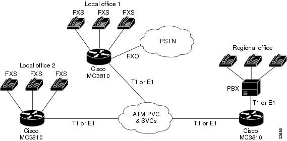
Figure 1 Application for Voice over ATM Using SVCs
Benefits
The Cisco MC3810 multiservice access concentrator formerly supported only non-dial permanent virtual circuits (PVCs) for ATM traffic.
SVCs offer the following benefits:
•
•
•
•
•
•
•
Restrictions
The following features are not supported.
•
•
•
•
•
•
•
Related Features and Technologies
The Cisco MC3810 also supports data over ATM SVCs. Wide-Area Networking Configuration Guide and Wide-Area Networking Command Reference provide more information about the commands and configuration steps required for this capability.
Related Documents
For information about Cisco IOS configuration for voice applications, consult the following Cisco IOS Release 12.0 documents:
•
•
For information about Cisco IOS configuration for ATM, consult the following Cisco IOS Release 12.0 documents:
•
•
For information about IOS configuration that is unique to the Cisco MC3810, consult the following Cisco documents:
•
•
Supported Platforms
This feature is supported on the Cisco MC3810 multiservice access concentrator.
Supported Standards, MIBs, and RFCs
No MIBs are supported by this feature.
Other Standards
•
•
•
•
•
•
•
•
Prerequisites
•
•
Configuration Tasks
Perform the following tasks to configure VoATM SVCs service:
•
•
•
These tasks do not represent all of the configuration tasks required to set up your ATM network. For more information, refer to the Cisco MC3810 Multiservice Access Concentrator Software Configuration Guide and to the examples shown in the "Configuration Examples" section.
Configuring Network Clocks and Controller Settings
Because voice communications require a continuous and tightly meshed data stream to avoid loss of information, and PSTNs provide a variety of clocks, you must synchronize source and destination devices to a single master clock. In the example that follows, the clock source is derived from a device attached to T1 controller 0; then the clock source is distributed to the devices attached to the local Cisco MC3810 serial ports and to T1 controller 1. Base clock source decisions on the network configuration, and set up a hierarchy of clock sources, so that backup clock sources are available. For details, see Chapter 4, "Configuring Synchronized Clocking," in Cisco MC3810 Multiservice Access Concentrator Software Configuration Guide.
This configuration task also includes the basic steps required for ATM support over T1/E1 controller 0.
Verifying Network Clocks and Controller Settings
To verify the configuration of network clock sources and controller settings, follow the steps below.
Step 1
Router# show network-clocksPriority 1 clock source(inactive config): T1 0Priority 1 clock source(active config) : T1 0Step 2
router# show controller t1 1T1 1 is up.Applique type is Channelized T1Cablelength is long gain36 0dbNo alarms detected.Slot 4 CSU Serial #07789650 Model TEB HWVersion 4.70 RX level = 0DBFraming is ESF, Line Code is B8ZS, Clock Source is Internal.Data in current interval (819 seconds elapsed):0 Line Code Violations, 0 Path Code Violations0 Slip Secs, 0 Fr Loss Secs, 0 Line Err Secs, 0 Degraded Mins0 Errored Secs, 0 Bursty Err Secs, 0 Severely Err Secs, 0 Unavail SecsData in Interval 1:0 Line Code Violations, 0 Path Code Violations0 Slip Secs, 0 Fr Loss Secs, 0 Line Err Secs, 0 Degraded Mins0 Errored Secs, 0 Bursty Err Secs, 0 Severely Err Secs, 0 Unavail SecsData in Interval 2:0 Line Code Violations, 0 Path Code Violations0 Slip Secs, 0 Fr Loss Secs, 0 Line Err Secs, 0 Degraded Mins0 Errored Secs, 0 Bursty Err Secs, 0 Severely Err Secs, 0 Unavail Secs...Data in Interval 96:0 Line Code Violations, 0 Path Code Violations0 Slip Secs, 0 Fr Loss Secs, 0 Line Err Secs, 0 Degraded Mins0 Errored Secs, 0 Bursty Err Secs, 0 Severely Err Secs, 0 Unavail SecsTotal Data (last 24 hours)0 Line Code Violations, 0 Path Code Violations,0 Slip Secs, 0 Fr Loss Secs, 0 Line Err Secs, 0 Degraded Mins,0 Errored Secs, 0 Bursty Err Secs, 0 Severely Err Secs, 0 Unavail Secs!Router# show controllers E1 1E1 1 is up.Applique type is Channelized E1 - balancedNo alarms detected.Slot 4 Serial #06868949 Model TEB HWVersion 3.80Framing is CRC4, Line Code is HDB3, Clock Source is Internal.Data in current interval (292 seconds elapsed):0 Line Code Violations, 0 Path Code Violations0 Slip Secs, 0 Fr Loss Secs, 0 Line Err Secs, 0 Degraded Mins0 Errored Secs, 0 Bursty Err Secs, 0 Severely Err Secs, 0 Unavail Secs...Total Data (last 66 15 minute intervals):9 Line Code Violations, 0 Path Code Violations,1 Slip Secs, 0 Fr Loss Secs, 4 Line Err Secs, 0 Degraded Mins,5 Errored Secs, 0 Bursty Err Secs, 0 Severely Err Secs, 0 Unavail SeConfiguring ATM Interfaces
In this section, the ATM interface is set up, including PVCs to carry signaling for SVCs. In addition, an NSAP address for an ATM SVC is specified. For additional information, see Cisco MC3810 Multiservice Access Concentrator Software Configuration Guide and Cisco MC3810 Multiservice Access Concentrator Software Command Reference.
You can also configure PVCs for voice communications. Wide-Area Networking Configuration Guide and Wide-Area Networking Command Reference provide additional information about this and other aspects of ATM configuration.
1
Router# configure terminalEnter global configuration mode.
2
Router(config)# interface atm0Enter interface configuration mode for ATM 0—the only ATM interface that supports voice over SVCs.
3
Assign the IP address and subnet mask to the interface.
4
#atm voice aesa {default |
esi-address}This command sets the unique ATM end-station address (AESA) for an ATM interface that is using SVC mode for voice.
The default keyword automatically creates an NSAP address for the interface, based on a prefix from the ATM switch (26 hexadecimal characters), the MAC address (12 hexadecimal characters) as the ESI (end station identifier), and a selector byte (two hexadecimal characters).
The esi-address option requires that you enter 12 hexadecimal characters as the ESI. The ATM switch provides the prefix and the voice selector byte provides the remaining characters.
You can view the assigned address using the show atm video-voice address command.
5
(config-if)#pvc [name] vpi/vci ilmiCreate an ATM permanent virtual circuit (PVC) for ILMI management purposes and enter PVC configuration mode.
The optional name is a unique label that can be up to 16 characters long. name identifies to the processor the virtual path identifier-virtual channel identifier (VPI-VCI) pair to use for a particular packet.
The ATM network VPI of this PVC is an 8-bit field in the header of the ATM cell. The vpi value is unique only on a single link, not throughout the ATM network, because it has local significance only. The vpi value must match that of the switch. Valid values are from 0 to 255, but the value is usually 0 for ILMI communications. If not specified, the vpi value is set to 0.
You cannot set both vpi and vci to 0; if one is 0, the other cannot be 0.
For ILMI communications this value is typically 16. The VCI is a 16-bit field in the header of the ATM cell. The VCI value is unique only on a single link—not throughout the ATM network—because it has local significance only.
To set up communication with the ILMI, enter a value of ilmi for ATM adaptation layer encapsulation; the associated vpi and vci values are ordinarily 0 and 16, respectively.
Note
6
(config-if-atm-pvc)#pvc [name] vpi/vci qsaalSee the explanations in Step 5 for the name, vpi, and vci values.
To enable the signaling for setup and tear-down of SVCs, specify the Q.SAAL (Signaling ATM Adaptation Layer) encapsulation; the associated vpi and vci values are ordinarily 0 and 5, respectively. You cannot create this PVC on a subinterface.
7
(config-if-atm-pvc)#exitExit PVC interface configuration mode.
8
interface atm 0 [.subinterface-number
{multipoint | point-to-point}]Optionally, you can create and configure a subinterface. This is useful when you wish to configure an extra parameter on the ATM interface. For example, you can specify one IP address on the main interface, as shown in Step 3; then you can configure a second IP address on a subinterface.
subinterface-number is a value in the range from 1 to 4294967293.
Enter the multipoint keyword when your network is fully meshed and you want to communicate with multiple routers. The point-to-point keyword configures the subinterface for communication with one router, as in a hard-wired connection. There is no default for this parameter.
Verifying ATM Interface Configuration
To verify ATM interface configuration, follow the steps below:
Step 1
Router# show atm vcVCD / Peak Avg/Min BurstInterface Name VPI VCI Type Encaps SC Kbps Kbps Cells Sts0 1 0 5 PVC SAAL UBR 0 UP0 2 0 16 PVC ILMI UBR 0 UP0 379 0 60 SVC SNAP UBR 0 UP0 986 0 84 SVC SNAP UBR 0 UP0 14 0 133 SVC VOICE VBR 64 16 10 UP0 15 0 134 SVC VOICE VBR 64 16 10 UP0 16 0 135 SVC VOICE VBR 64 16 10 UP0 17 0 136 SVC VOICE VBR 64 16 10 UP0 18 0 137 SVC VOICE VBR 64 16 10 UP0 19 0 138 SVC VOICE VBR 64 16 10 UP0 20 0 139 SVC VOICE VBR 64 16 10 UP0 21 0 140 SVC VOICE VBR 64 16 10 UP0 22 0 141 SVC VOICE VBR 64 16 10 UP0 23 0 142 SVC VOICE VBR 64 16 10 UP0 24 0 143 SVC VOICE VBR 64 16 10 UP0 25 0 144 SVC VOICE VBR 64 16 10 UP0 26 0 145 SVC VOICE VBR 64 16 10 UP0 27 0 146 SVC VOICE VBR 64 16 10 UP0 28 0 147 SVC VOICE VBR 64 16 10 UPStep 2
Router# show atm svc 0/134ATM0: VCD: 5, VPI: 0, VCI: 134VBR, PeakRate: 64000AAL5, etype: 0x0, Flags 0x440, VCmode: 0xE000OAM frequency: 0 second(s), OAM retry frequency: 1 second(s)OAM up retry count: 3, OAM down retry count: 5OAM Loopback status: OAM DisabledOAM VC state: Not ManagedILMI VC state: Not ManagedInARP DISABLEDInPkts: 4, OutPkts: 4, InBytes: 432, OutBytes: 432InPRoc: 4, OutPRoc: 4, Broadcasts: 0InFast: 0, OutFast: 0, InAS: 0, OutAS: 0OAM cells received: 0F5 InEndloop: 0, F5 InSegloop: 0, F5 InAIS: 0, F5 InRDI:0F4 InEndloop: 0, F4 InSegloop: 0, F4 InAIS: 0, F4 InRDI:0OAM cells sent: 0F5 OutEndloop: 0, F5 OutSegloop: 0, F5 OutRDI: 0OAM cell drops: 0Status: UPTTL: 3interface = ATM0, call locally initiated, call reference = 5558610vcnum = 5, vpi = 0, vci = 134, state = Active(U10), point-to-point callRetry count: Current = 0timer currently inactive, timer value = 00:00:00Remote Atm Nsap address:47.00918100000000400B0A2501.0060837B4743.00, VCowner:Static MapStep 3
Router# show atm pvc 0/5ATM0: VCD: 2, VPI: 0, VCI: 5, Connection Name: SAALUBR, PeakRate: 56AAL5-SAAL, etype:0x4, Flags: 0x26, VCmode: 0x0OAM frequency: 0 second(s), OAM retry frequency: 1 second(s), OAM retry frequency: 1 second(s)OAM up retry count: 3, OAM down retry count: 5OAM Loopback status: OAM DisabledOAM VC state: Not ManagedILMI VC state: Not ManagedInARP DISABLEDInPkts: 2044, OutPkts: 2064, InBytes: 20412, OutBytes: 20580InPRoc: 2044, OutPRoc: 2064, Broadcasts: 0InFast: 0, OutFast: 0, InAS: 0, OutAS: 0OAM cells received: 0F5 InEndloop: 0, F5 InSegloop: 0, F5 InAIS: 0, F5 InRDI: 0F4 InEndloop: 0, F4 InSegloop: 0, F4 InAIS: 0, F4 InRDI: 0OAM cells sent: 0F5 OutEndloop: 0, F5 OutSegloop: 0, F5 OutRDI: 0F4 OutEndloop: 0, F4 OutSegloop: 0, F4 OutRDI: 0OAM cell drops: 0Compress: DisabledStatus: INACTIVE, State: NOT_IN_SERVICE!Router# show atm pvc 0/16ATM0: VCD: 1, VPI: 0, VCI: 16, Connection Name: ILMIUBR, PeakRate: 56AAL5-ILMI, etype:0x0, Flags: 0x27, VCmode: 0x0OAM frequency: 0 second(s), OAM retry frequency: 1 second(s), OAM retry frequency: 1 second(s)OAM up retry count: 3, OAM down retry count: 5OAM Loopback status: OAM DisabledOAM VC state: Not ManagedILMI VC state: Not ManagedInARP DISABLEDInPkts: 398, OutPkts: 421, InBytes: 30493, OutBytes: 27227InPRoc: 398, OutPRoc: 421, Broadcasts: 0InFast: 0, OutFast: 0, InAS: 0, OutAS: 0OAM cells received: 0F5 InEndloop: 0, F5 InSegloop: 0, F5 InAIS: 0, F5 InRDI: 0F4 InEndloop: 0, F4 InSegloop: 0, F4 InAIS: 0, F4 InRDI: 0OAM cells sent: 0F5 OutEndloop: 0, F5 OutSegloop: 0, F5 OutRDI: 0F4 OutEndloop: 0, F4 OutSegloop: 0, F4 OutRDI: 0OAM cell drops: 0Compress: DisabledStatus: INACTIVE, State: NOT_IN_SERVICEStep 4
Router# show interface atm 0ATM0 is up, line protocol is upHardware is PQUICC Atom1Internet address is 9.1.1.6/8MTU 1500 bytes, sub MTU 1500, BW 1536 Kbit, DLY 20000 usec,reliability 255/255, txload 22/255, rxload 11/255NSAP address: 47.0091810000000002F26D4901.000011116666.06Encapsulation ATM292553397 packets input, -386762809 bytes164906758 packets output, 1937663833 bytes0 OAM cells input, 0 OAM cells output, loopback not setKeepalive not supportedEncapsulation(s):, PVC mode1024 maximum active VCs, 28 current VCCsVC idle disconnect time: 300 secondsSignalling vc = 1, vpi = 0, vci = 5UNI Version = 4.0, Link Side = userLast input 00:00:00, output 2d05h, output hang neverLast clearing of "show interface" counters neverInput queue: -1902/75/0 (size/max/drops); Total output drops: 205Queueing strategy: weighted fairOutput queue: 0/1000/64/0 (size/max total/threshold/drops)Conversations 0/0/256 (active/max active/max total)Reserved Conversations 0/0 (allocated/max allocated)5 minute input rate 67000 bits/sec, 273 packets/sec5 minute output rate 136000 bits/sec, 548 packets/sec76766014 packets input, 936995443 bytes, 0 no bufferReceived 0 broadcasts, 0 runts, 0 giants, 0 throttles0 input errors, 0 CRC, 0 frame, 0 overrun, 0 ignored, 0 abort367264676 packets output, 3261882795 bytes, 0 underruns0 output errors, 0 collisions, 2 interface resets0 output buffer failures, 0 output buffers swapped outStep 5
Router# show atm video-voice addressnsap address type ilmi status47.0091810000000002F26D4901.00107B4832E1.FE VOICE_AAL5 Confirmed47.0091810000000002F26D4901.00107B4832E1.C8 VIDEO_AAL1 ConfirmedConfiguring Voice Ports and Voice Dial Peers
In this section, the voice ports and voice dial peers are set up to support the local and the remote parties.
1
Router# configure terminalEnter global configuration mode.
2
Specify a voice port and enter voice-port configuration mode.
port specifies the slot number on the Cisco MC3810. If the analog voice module (AVM) or the digital voice module (DVM) is installed, the slot number is 1. If the multiflex trunk (MFT) is installed, the slot number is 0.
slot specifies the voice port number. The valid entries depend on the hardware configuration, as follows:
•
•
•
3
Router(config-voiceport) codec g726r32or see Step 6.
(Fax only, Optional) If you are configuring a dial peer for faxes over ATM SVCs, the default codec setting for the voice port does not function properly with the typical fax rate of 9.600 bps. Therefore, you can either change the codec or change the fax rate. The codec must support a minimum of 22 kbps.
To change the codec from the default g729ar8 codec (8 kbps), enter the voice-port codec command to specify one of the following compression modes:
•
•
•
4
Router(config-voiceport) exitExit voice-port configuration mode.
5
(config)# dial-peer voice tag voatmDefine a voice ATM dial peer for the remote system and enter dial-peer configuration mode. Voice dial peers are persistent and exist until they are specifically removed with the no form of the dial-peer voice command.
The tag value identifies the dial peer and must be unique on the Cisco MC3810. Do not duplicate a specific tag number. Valid values are from 1 to 10000.
6
(config-dialpeer)#fax rate 4800(Fax only, Optional) If you are configuring a dial peer for faxes over ATM SVCs, the default codec setting for the voice port does not function properly unless the fax rate is slowed from the typical speed of 9.600 bps. Therefore, you can either change the codec (see Step 3) or change the fax rate to 4,800 bps or 2,400 bps.
7
(config-dialpeer)#destination-pattern string [T]Configure the dial peer's destination pattern to allow the system to reconcile dialed digits with the peer's NSAP address. The string is a series of digits that specify the E.164 or private dialing plan telephone number. Valid entries are the digits 0 through 9 and the letters A through D. The plus symbol (+) is not valid. You can enter the following special characters:
•
•
•
•
8
(config-dialpeer)#session target ATM0 {svc nsap
address |pvc [vpi/vci | name]}Configure the ATM session target for the dial peer. Specify ATM 0 as the interface.
When you use SVCs, the system reconciles dialed digits with the remote ATM interface's voice NSAP address.
Note
9
(config-dialpeer)# exitExit dial-peer configuration mode for this particular dial peer.
10
(config)# dial-peer voice tag potsDefine a local voice ATM dial peer.
The tag value identifies the dial peer and must be unique on the Cisco MC3810. Do not duplicate a specific tag number. Valid values are from 1 to 10000.
11
(config-dialpeer)#destination-pattern stringConfigure the dial peer's destination pattern. See Step 7 for more information.
12
(config-dialpeer)#port slot/portSpecify the voice port where the voice equipment is connected.
Verifying Voice Ports and Voice Dial Peers
Step 1
Router# show voice port 1/1Voice-port1/1 Slot is 1, Port is 1Type of VoicePort is E&MOperation State is UPAdministrative State is UPNo Interface Down FailureDescription is not setNoise Regeneration is enabledNon Linear Processing is enabledMusic On Hold Threshold is Set to -38 dBmIn Gain is Set to 0 dBOut Attenuation is Set to 0 dBEcho Cancellation is enabledEcho Cancel Coverage is set to 8 msConnection Mode is normalConnection Number is not setInitial Time Out is set to 10 sInterdigit Time Out is set to 10 sCall-Disconnect Time Out is set to 0 sCoder Type is g729ar8Companding Type is u-lawVoice Activity Detection is disabledRinging Time Out is 180 sWait Release Time Out is 30 sNominal Playout Delay is 80 millisecondsMaximum Playout Delay is 160 millisecondsRx A bit no conditioning setRx B bit no conditioning setRx C bit no conditioning setRx D bit no conditioning setTx A bit no conditioning setTx B bit no conditioning setTx C bit no conditioning setTx D bit no conditioning setTx Busyout ABCD bits = 1010 Default patternRx Seize ABCD bits = 1111 Default patternRx Idle ABCD bits = 0000 Default patternTx Seize ABCD bits = 1111 Default patternTx Idle ABCD bits = 0000 Default patternIgnored Rx ABCD bits = BCDRegion Tone is set for USAnalog Info Follows:Currently processing VoiceMaintenance Mode Set to None (not in mtc mode)Number of signaling protocol errors are 0Impedance is set to 600r OhmVoice card specific Info Follows:Signal Type is immediateOperation Type is 2-wireE&M Type is 1Dial Type is dtmfIn Seizure is activeOut Seizure is activeDigit Duration Timing is set to 100 msInterDigit Duration Timing is set to 100 msPulse Rate Timing is set to 10 pulses/secondInterDigit Pulse Duration Timing is set to 500 msClear Wait Duration Timing is set to 400 msWink Wait Duration Timing is set to 200 msWink Duration Timing is set to 200 msDelay Start Timing is set to 150 msDelay Duration Timing is set to 140 msDial Pulse Min. Delay is set to 140 msAuto Cut-through is disabledPercent Break of Pulse is 61 percentDialout Delay for immediate start is 300 msStep 2
Router# show dial-peer voiceVoiceEncapPeer1tag = 1, destination-pattern = `4002',preference = 0,Admin state is up, Operation state is uptype = pots, prefix = `', fwd-digits = 0,session-target = `', voice-port = 1/1VoiceOverATMPeer2tag = 2, destination-pattern = `4001',preference = 0,Admin state is up, Operation state is uptype = voatm, session-target = 'ATM0'nsap '47.0091810000000050E201B101.00107B09C6ED.FE',VoiceEncapPeer3tag = 3, destination-pattern = `4003',preference = 0,Admin state is up, Operation state is uptype = pots, prefix = `', fwd-digits = 0,session-target = `', voice-port = 1/1Step 3
router# show dialplan number 5558809Macro Exp.: 3388809VoiceEncapPeer9information type = voice,tag = 9, destination-pattern = `5558809',answer-address = `', preference=0,group = 9, Admin state is up, Operation state is up,incoming called-number = `', connections/maximum = 0/unlimited,application associated:type = pots, prefix = `',session-target = `', voice-port = `1/9',direct-inward-dial = disabled,register E.164 number with GK = TRUEConnect Time = 0, Charged Units = 0,Successful Calls = 0, Failed Calls = 0,Accepted Calls = 0, Refused Calls = 0,Last Disconnect Cause is "",Last Disconnect Text is "",Last Setup Time = 0.Matched: 5558809 Digits: 7Target:Troubleshooting Voice over ATM SVCs
When problems occur with voice over ATM SVCs, follow the steps below to look first for simpler problems before progressing to more complex possible issues. For general information about troubleshooting and voice QoS, see Cisco IOS Release 12.0 Voice, Video, and Home Applications Configuration Guide. Please see if any additional steps should be mentioned here.
Step 1
Step 2
Router# show atm pvcVCD / Peak Avg/Min BurstInterface Name VPI VCI Type Encaps SC Kbps Kbps Cells Sts0 1 0 5 PVC SAAL UBR 56 UP0 2 0 16 PVC ILMI UBR 56 UPStep 3
router# show atm video-voice addressnsap address type ilmi status47.0091810000000002F26D4901.00107B4832E1.FE VOICE_AAL5 Confirmedrouter# show atm ilmi-statusInterface : ATM0 Interface Type : Private UNI (User-side)ILMI VCC : (0, 16) ILMI Keepalive : Enabled (5 Sec 4 Retries)ILMI State: UpAndNormalPeer IP Addr: 10.1.1.11 Peer IF Name: ATM1/0/0Peer MaxVPIbits: 8 Peer MaxVCIbits: 14Active Prefix(s) :47.0091.8100.0000.0002.f26d.4901End-System Registered Address(s) :47.0091.8100.0000.0002.f26d.4901.0000.1111.5555.05(Confirmed)47.0091.8100.0000.0002.f26d.4901.0010.7b48.32e1.fe(Confirmed)47.0091.8100.0000.0002.f26d.4901.0010.7b48.32e1.c8(Confirmed)Step 4
router# show voice busyoutIf following network interfaces are down, voice port will be put into busyout state Serial0The following voice ports are in busyout state 1/10Enter show interfaces serial to check the specified serial interface, or enter show voice port to check the voice-port status. The no form of the busyout forced command restores the voice port.
Step 5
...Data in current interval (819 seconds elapsed):0 Line Code Violations, 0 Path Code Violations0 Slip Secs, 0 Fr Loss Secs, 0 Line Err Secs, 0 Degraded Mins0 Errored Secs, 0 Bursty Err Secs, 0 Severely Err Secs, 0 Unavail SecsData in Interval 1:0 Line Code Violations, 0 Path Code Violations0 Slip Secs, 0 Fr Loss Secs, 0 Line Err Secs, 0 Degraded Mins0 Errored Secs, 0 Bursty Err Secs, 0 Severely Err Secs, 0 Unavail SecsData in Interval 2:0 Line Code Violations, 0 Path Code Violations0 Slip Secs, 0 Fr Loss Secs, 0 Line Err Secs, 0 Degraded Mins0 Errored Secs, 0 Bursty Err Secs, 0 Severely Err Secs, 0 Unavail SecsData in Interval 3:0 Line Code Violations, 0 Path Code Violations0 Slip Secs, 0 Fr Loss Secs, 0 Line Err Secs, 0 Degraded Mins0 Errored Secs, 0 Bursty Err Secs, 0 Severely Err Secs, 0 Unavail Secs...A few slip errors may not indicate a problem with clocking. However, if there are numerous errors, especially incrementing numbers of errors, you should check the following possibilities:
–
–
Step 6
router# show sscopSSCOP details for interface ATM0Current State = Data Transfer ReadyInterpretation of the command output requires familiarity with SSCOP, so unless you understand the protocol, just use the command to ensure that the protocol is in a state of readiness, as shown above. If you need to make changes, see the Cisco IOS Release 12.0 documents, Wide-Area Networking Configuration Guide and Wide-Area Networking Command Reference.
Note
Step 7
Router1# show dial-peer voiceVoiceEncapPeer33tag = 1, destination-pattern = `5558810',preference = 0,Admin state is up, Operation state is uptype = pots, prefix = `', fwd-digits = 0,session-target = `', voice-port = 1/1VoiceOverATMPeer333tag = 2, destination-pattern = `559...',preference = 0,Admin state is up, Operation state is uptype = voatm, session-target = 'ATM0'nsap '47.0091810000000002F26D4901.567856785678.56',Router2# show dial-peer voiceVoiceEncapPeer44tag = 20, destination-pattern = `5559810',preference = 0,Admin state is up, Operation state is uptype = pots, prefix = `', fwd-digits = 0,session-target = `', voice-port = 1/1VoiceOverATMPeer444tag = 10, destination-pattern = `5558...',preference = 0,Admin state is up, Operation state is uptype = voatm, session-target = 'ATM0'nsap '47.0091810000000002F26D4901.100110011001.01',Step 8
router# show call history voice recordConnectionId=[0x9CE20881 0x224855C1 0x0 0x1C9B84C7]Media=TELE, TxDuration= 301962 msCallingNumber=6668808SetupTime=47995411 x 10msConnectTime=47995671 x 10msDisconectTime=48025867 x 10msDisconnectText=local onhookConnectionId=[0x9CE20881 0x224855C1 0x0 0x1C9B84C7]Media=ATM, LowerIfName=ATM0, VPI=0, VCI=299CalledNumber=5559808SetupTime=47995483 x 10msConnectTime=47995671 x 10msDisconectTime=48025867 x 10msDisconnectText=remote onhookConnectionId=[0x9CE20881 0x224855C2 0x0 0x1C9B84CB]Media=TELE, TxDuration= 301950 msCallingNumber=5558803SetupTime=47995412 x 10msConnectTime=47995682 x 10msDisconectTime=48025877 x 10msDisconnectText=local onhookMonitoring and Maintaining Voice over ATM SVCs
Configuration Examples
This example shows the configurations of two Cisco MC3810 multiservice access concentrators that each have voice dial peers connecting over ATM SVCs. For additional information, see the Cisco MC3810 Multiservice Access Concentrator Software Configuration Guide and the Cisco MC3810 Multiservice Access Concentrator Software Command Reference.
Figure 2 Sample Configuration: Two Cisco MC3810s using ATM SVCs for Voice

Initially, the network clocks are set up on MC3810A and MC3810B.
The following configuration sets the T1 0 controllers, which are for ATM service. ESF framing and B8ZS are required for ATM. The default clock source is line, and the default for the T1 1 controller automatically becomes internal.
The following configuration shows how the T1 1 controllers are set up for channel-associated signaling (CAS) through the mode cas command. A voice group is created on each controller to specify all of the DS0s for CAS and to set up E&M immediate-start signaling for the voice ports.
The following commands show how to configure the ATM interface and set up PVCs to supply Q.SAAL signaling and ILMI management for SVC communications. Note that you can also specify the voice NSAP address by using the atm voice aesa command with an ESI value.
The following commands specify the voice ports corresponding to the DS0s. Not all are shown.
The following commands specify the local voice dial peers (all 24 are not shown) and the ATM dial peers.
Command Reference
This section documents new or modified commands. All other commands used with this feature are documented in the Cisco IOS Release 12.0 command reference publications.
In Cisco IOS Release 12.0(1)T or later, you can search and filter the output for show and more commands. This functionality is useful when you need to sort through large amounts of output, or if you want to exclude output that you do not need to see.
To use this functionality, enter a show or more command followed by the "pipe" character (|), one of the keywords begin, include, or exclude, and an expression that you want to search or filter on:
command | {begin | include | exclude} regular-expression
Following is an example of the show atm vc command in which you want the command output to begin with the first line where the expression "PeakRate" appears:
show atm vc | begin PeakRate
For more information on the search and filter functionality, refer to the Cisco IOS Release 12.0(1)T feature module titled CLI String Search.
atm scramble-enable
Scrambling improves data reliability on E1links by randomizing the ATM cell payload frames to avoid continuous non-variable bit patterns and improve the efficiency of ATM's cell delineation algorithms. The no form disables scrambling.
atm scramble-enable
no atm scramble-enable
Syntax Description
This command has no arguments or keywords.
Defaults
By default, payload scrambling is off.
Command Mode
Interface configuration
Command History
12.0(5)XK and 12.0(7)T
This command was introduced for ATM interface configuration on the Cisco MC3810.
Usage Guidelines
Enable scrambling on E1 links only. On T1 links, the default B8ZS line encoding normally ensures sufficient reliability.
The scrambling setting must match that of the far end.
Example
On a Cisco MC3810, the following example shows how to set the ATM0 E1 link to scramble payload:
interface atm0atm scramble-enableatm voice aesa
Enter the atm voice aesa ATM interface configuration command to set the unique ATM end-station address (AESA) for an ATM voice interface using SVC mode. The no form of this command removes any configured address for the interface.
atm voice aesa [default | esi-address]
no atm voice aesa
Syntax Description
Defaults
The default keyword is the default.
Command Mode
Interface configuration
Command History
12.0(5)XK and 12.0(7)T
This command was introduced for ATM interface configuration on the Cisco MC3810.
Usage Guidelines
You cannot specify the ATM interface NSAP address in its entirety. The system creates either all of it or part of it, depending upon how you use this command.
Examples
On a Cisco MC3810, the following example shows the ATM interface NSAP address set automatically:
interface atm0atm video aesa defaultOn a Cisco MC3810, the following example shows the ATM interface NSAP address set to a specific ESI value:
interface atm0/1atm video aesa 444444444444Related Command
show atm video-voice address
Allows you to review the address assigned to an ATM interface.
serial restart-delay
To set the amount of time that the router waits before trying to bring up a serial interface when it goes down, enter the serial restart-delay interface configuration command. The no form of the command set the delay to the default.
serial restart-delay count
no serial restart-delay
Syntax Description
count
count is a value from 0 to 900 in seconds. This is the frequency at which the hardware is reset.
Default
The default value is 0.
Command Mode
Interface configuration
Command History
12.0(5)XK and 12.0(7)T
This command was introduced for serial interface configuration on the Cisco MC3810.
Usage Guidelines
The router resets the hardware each time the serial restart timer expires. This command is often used with the dial backup feature and with the pulse-time command, which sets the amount of time to wait before redialing when a DTR dialed device fails to connect.
When the count value is set to 0, the hardware is not reset when it goes down. In this way, if the interface is used to answer a call, it does not cause DTR to drop, which might cause communications device to disconnect.
Example
On Cisco MC3810 interface Serial 0, this example shows the restart delay set to 1 second:
interface Serial0serial restart-delay 1Related Commands
pulse-time seconds
Enables pulsing DTR signal intervals on the serial interfaces.
show interface serial
Displays details serial interface configuration.
session target
To configure an ATM network-specific address for a permanent virtual connection (PVC) or switch virtual connection (SVC) dial peer, enter the ATM form of the session target dial-peer configuration command. The no form of the command disables the feature.
session target atm interface {svc nsap nsap-address | pvc {name | vpi/vci | vci}
no session target
Syntax Description
Default
Enabled with no IP address or domain name defined.
Command Mode
Dial-peer configuration
Command History
Usage Guidelines
Enter the ATM-specific version of this command to specify an ATM PVC or SVC for voice or video communications.
With SVCs and a dial map, dialed digits are reconciled with the remote ATM interface's voice NSAP address,
Example
The following example shows how an ATM voice dial peer is configured for SVC communications:
dial-peer voice 10 voatmdestination-pattern 555session target ATM0 svc nsap 47.0091810000000002F26D4901.444444444444.01Related Commands
dial-peer voice
Sets up a voice dial peer for a local or remote dial peer.
show dial-peer voice
Displays details about configured voice dial peers.
show atm video-voice address
To display the network service access point (NSAP) address for the ATM interface, enter the show atm video-voice address privileged EXEC command.
show atm video-voice address
Syntax Description
There are no keywords or arguments.
Default
No default behavior or values
Command History
Usage Guidelines
Enter this command to review ATM interface NSAP addresses that have been assigned using the atm video aesa or atm voice aesa command and to insure that ATM management is confirmed for those addresses.
Example
On a Cisco MC3810, the following example shows how to see information about ATM interface NSAP addresses:
router# show atm video-voice addressnsap address type ilmi status47.0091810000000002F26D4901.00107B4832E1.FE VOICE_AAL5 Confirmed47.0091810000000002F26D4901.00107B4832E1.C8 VIDEO_AAL1 ConfirmedTable 1 describes the fields in the command output.
Table 1
ilmi status
Indicates whether an ILMI PVC is set up and operational to manage SVC communications.
nsap address
ATM interface NSAP address.
type
Interface ATM encapsulation type.
show atm video-voice address Fields
Related Command
Glossary
AAL—ATM Adaptation Layer. Service-dependent sublayer of the data link layer. The AAL accepts data from different applications and presents it to the ATM layer in the form of 48-byte ATM payload segments. AALs consist of two sublayers: convergence sublayer (CS) and segmentation and reassembly (SAR). AALs differ on the basis of the source-destination timing used, whether they use constant bit rate (CBR) or variable bit rate (VBR), and whether they are used for connection-oriented or connectionless mode data transfer. At present, the four types of AAL recommended by the ITU-T are AAL1, AAL2, AAL3/4, and AAL5.
AAL1—ATM adaptation layer 1. One of four AALs recommended by the ITU-T. AAL1 is used for connection-oriented, delay-sensitive services requiring constant bit rates, such as uncompressed video and other isochronous traffic.
AAL5—ATM adaptation layer 5. One of four AALs recommended by the ITU-T. AAL5 supports connection-oriented VBR services and is used predominantly for the transfer of classical IP over ATM and LANE traffic. AAL5 uses simple and efficient AAL (SEAL) and is the least complex of the current AAL recommendations. It offers low bandwidth overhead and simpler processing requirements in exchange for reduced bandwidth capacity and error-recovery capability.
ABR—available bit rate. QoS class defined by the ATM Forum for ATM networks. ABR is used for connections that do not require timing relationships between source and destination. ABR provides no guarantees in terms of cell loss or delay, providing only best-effort service. Traffic sources adjust their transmission rate in response to information they receive describing the status of the network and its capability to successfully deliver data.
AESA—ATM End System Address
ATM—Asynchronous Transfer Mode. International standard for cell relay in which multiple service types (such as voice, video, or data) are conveyed in fixed-length (53-byte) cells. Fixed-length cells allow cell processing to occur in hardware, thereby reducing transit delays. ATM is designed to take advantage of high-speed transmission media such as E3, SONET, and T3.
CAS—channel-associated signaling
CBR—constant bit rate. QoS class defined by the ATM Forum for ATM networks. CBR is used for connections that depend on precise clocking to ensure undistorted delivery.
CCS—common-channel signaling
CES—circuit emulation service. Enables users to multiplex or concentrate multiple circuit emulation streams for voice and video with packet data on a single high-speed ATM link without a separate ATM access multiplexer.
E1—European digital carrier facility used for transmitting data through the telephone hierarchy. The transmission rate for E1 is 2.048 megabits per second (Mbps).
E3—Wide-area digital transmission scheme used predominantly in Europe that carries data at a rate of 34.368 Mbps. E3 lines can be leased for private use from common carriers.
ESI—end station identifier
ILMI—Interim Local Management Interface. Specification developed by the ATM Forum for incorporating network-management capabilities into the ATM User-Network Interface (UNI).
ISDN—Integrated Services Digital Network. Communication protocol, offered by telephone companies, that permits telephone networks to carry data, voice, and other source traffic.
NM—Network module
POTS—Plain Old Telephone Service. Basic telephone service supplying standard single-line telephones, telephone lines, and access to the public switched telephone network.
PVC—permanent virtual circuit. Virtual circuit that is permanently established. PVCs save bandwidth associated with circuit establishment and tear down in situations where certain virtual circuits must exist all the time. In ATM terminology, called a permanent virtual connection.
QoS—quality of service. Measure of performance for a transmission system that reflects its transmission quality and service availability.
SAR—segmentation and reassembly. One of the two sublayers of the AAL CPCS, responsible for dividing (at the source) and reassembling (at the destination) the PDUs passed from the CS. The SAR sublayer takes the PDUs processed by the CS and, after dividing them into 48-byte pieces of payload data, passes them to the ATM layer for further processing.
SONET—Synchronous Optical Network. High-speed (up to 2.5 Gbps) synchronous network specification developed by Bellcore and designed to run on optical fiber. STS-1 is the basic building block of SONET.
SSCS—service specific convergence sublayer. One of the two sublayers of any AAL. SSCS, which is service dependent, offers assured data transmission. The SSCS can be null as well, in classical IP over ATM or LAN emulation implementations.
SVC—switched virtual circuit. Virtual circuit that is dynamically established on demand and is torn down when transmission is complete. SVCs are used in situations where data transmission is sporadic. Called a switched virtual connection in ATM terminology.
T3—Digital WAN carrier facility. T3 transmits DS-3-formatted data at 44.736 Mbps through the telephone switching network.
UBR—unspecified bit rate. Quality of Service (QoS) class defined by the ATM Forum for ATM networks. UBR allows any amount of data up to a specified maximum to be sent across the network, but there are no guarantees in terms of cell loss rate and delay.
UNI—User-Network Interface. ATM Forum specification that defines an interoperability standard for the interface between ATM-based products (a router or an ATM switch) located in a private network and the ATM switches located within the public carrier networks. Also used to describe similar connections in Frame Relay networks.
VBR—variable bit rate. QoS class defined by the ATM Forum for ATM networks. VBR is subdivided into a real time (RT) class and non-real time (NRT) class. VBR (RT) is used for connections in which there is a fixed timing relationship between samples. VBR (NRT) is used for connections in which there is no fixed timing relationship between samples, but that still need a guaranteed QoS.
VC—virtual circuit. Logical circuit created to ensure reliable communication between two network devices. A virtual circuit is defined by a VPI/VCI pair, and can be either permanent (PVC) or switched (SVC). Virtual circuits are used in Frame Relay and X.25. In ATM, a virtual circuit is called a virtual channel.
VCI—virtual channel identifier. 16-bit field in the header of an ATM cell. The VCI, together with the virtual path identifier (VPI), is used to identify the next destination of a cell as it passes through a series of ATM switches on its way to its destination. ATM switches use the VPI/VCI fields to identify the next network virtual channel link (VCL) that a cell needs to transit on its way to its final destination.
VCL—virtual channel link. Connection between two ATM devices. A VCC is made up of one or more VCLs.
VPI—virtual path identifier. 8-bit field in the header of an ATM cell. The VPI, together with the VCI, is used to identify the next destination of a cell as it passes through a series of ATM switches on its way to its destination. ATM switches use the VPI/VCI fields to identify the next VCL that a cell needs to transit on its way to its final destination.

Any Internet Protocol (IP) addresses used in this document are not intended to be actual addresses. Any examples, command display output, and figures included in the document are shown for illustrative purposes only. Any use of actual IP addresses in illustrative content is unintentional and coincidental.
© 2007 Cisco Systems, Inc. All rights reserved.
 Feedback