Configuring Multihop VPDN
Available Languages
Table Of Contents
Prerequisites for Multihop VPDN
Information About Multihop VPDN
Multihop VPDN with an MMP Stack Group
L2TP Redirect for MMP Multihop Deployments
Tunnel Switching Using Multihop VPDN
How to Configure Multihop VPDN
Configuring an MMP Stack Group for Multihop VPDN
Configuring L2TP Redirect for MMP VPDNs
Number of Redirect Attempts on the NAS
Load Balancing Calls Using L2TP Redirect
Prerequisites for Configuring L2TP Redirect
Restrictions for Configuring L2TP Redirect
Enabling Multihop VPDN on the NAS
Configuring the Redirect Identifier on the NAS
Configuring the Redirect Identifier on the RADIUS Server
Configuring the Redirect Identifier on the Stack Group Tunnel Servers
Configuring the Redirect Source on the Stack Group Tunnel Servers
Monitoring L2TP Redirect Configurations
Configuring a Multihop Tunnel Switch
Prerequisites for Configuring a Multihop Tunnel Switch
Restrictions for Configuring a Multihop Tunnel Switch
Enabling Multihop VPDN on the Tunnel Switch
Configuring the Multihop Tunnel Switch to Terminate Incoming VPDN Tunnels
Configuring the Multihop Tunnel Switch to Initiate Outgoing VPDN Tunnels
Configuration Examples for Multihop VPDN
Configuring Multihop VPDN on an MMP Stack Group: Example
Configuring L2TP Redirect: Example
Configuring L2TP Redirect with a Redirect Identifier: Example
Configuring Redirect Identifiers on the RADIUS Server: Example
Configuring the Redirect Source on a Stack Group Tunnel Server: Example
Configuring Multihop VPDN Tunnel Switching: Example
Feature Information for Multihop VPDN
Configuring Multihop VPDN
Multihop virtual private dialup networking (VPDN) is a specialized VPDN configuration that allows packets to pass through multiple tunnels. Ordinarily, packets are not allowed to pass through more than one tunnel. In a multihop deployment, the VPDN tunnel is terminated after each hop and a new tunnel is initiated to the next hop destination.
Multihop VPDN deployments are required when the remote private network uses Multichassis Multilink PPP (MMP) with multiple tunnel servers in a stack group.
Multihop VPDN deployments can also be used to configure a device as a tunnel switch. A tunnel switch acts as both a network access server (NAS) and a tunnel server, able to receive packets from an incoming VPDN tunnel and send them out over an outgoing VPDN tunnel. Tunnel switch configurations can be used between Internet service providers (ISPs) to provide wholesale VPDN services.
All of the tasks documented in this module require that tasks documented elsewhere in the Cisco IOS VPDN Configuration Guide have first been completed.
Module History
This module was first published on October 31, 2005, and last updated on February 28, 2006.
Finding Feature Information in This Module
Your Cisco IOS software release may not support all features. To find information about feature support and configuration, use the "Feature Information for Multihop VPDN" section.
Contents
•
Prerequisites for Multihop VPDN
•
•
•
•
Prerequisites for Multihop VPDN
Before you configure multihop VPDN, a VPDN deployment must be configured. For more information about VPDN deployments that are compatible with multihop VPDN scenarios, see the sections "Configuring an MMP Stack Group for Multihop VPDN" or "Configuring a Multihop Tunnel Switch."
Information About Multihop VPDN
Multihop VPDN allows packets to pass through multiple tunnels. Ordinarily, packets are not allowed to pass through more than one tunnel. In a multihop deployment, the VPDN tunnel is terminated after each hop and a new tunnel is initiated to the next hop destination. A maximum of four hops is supported.
The following sections contain information about multihop VPDN deployments:
•
•
•
Multihop VPDN with an MMP Stack Group
Multihop VPDN is required when a VPDN tunnel delivers Multilink PPP (MLP) data to a private network that uses an MMP stack group.
MLP provides the capability of splitting and recombining packets to a single end system across a logical pipe (also called a bundle) formed by multiple links.
MMP deployments link multiple tunnel servers in a stack group. Different members of a stack group may terminate MLP links from the same source. Stack group tunnel servers must establish Layer 2 tunnels between each other so that MLP packets from a single host can be properly recombined. If the incoming MLP data is delivered to the stack group over a VPDN tunnel, multihop VPDN is required for the stack group to function.
MMP using multihop VPDN can use only the Layer 2 Tunnel Protocol (L2TP) or Layer 2 Forwarding (L2F) protocol on the NAS and the stack group members.
Figure 20 shows a network scenario using a multihop VPDN with a MMP deployment.
Figure 20 MMP Using Multihop VPDN
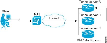
Data from the client is tunneled from the NAS to a stack group member using either L2TP or L2F. If the client is using MLP, multiple data links may terminate on different stack members. Stack group bidding protocol (SGBP) is used to determine which stack member is the MLP bundle owner. Tunnel servers that receive calls belonging to a bundle owned by a different stack group member will forward those calls to the owner using an L2TP or L2F tunnel. Because the data must traverse two VPDN tunnels in this scenario, multihop VPDN must be enabled.
For more information on stack group configuration, refer to the "Implementing Multichassis Multilink PPP" module in the Cisco IOS Dial Technologies Configuration Guide, Release 12.4.
L2TP Redirect for MMP Multihop Deployments
In a traditional MMP deployment, the stack group tunnel servers use L2TP or L2F tunnels to deliver MLP links to the bundle owner. This architecture does not easily scale beyond a few routers per tunnel server stack, and inherently adds hops and latency variations between links in a bundle.
Enabling L2TP redirect allows a stack group member to send a redirect message to the NAS if it receives a link that is owned by another stack group member. L2TP redirect increases the scalability of MMP deployments, load balances sessions across the stack group tunnel servers, and smooths traffic as all links in a multilink bundle experience the same delay and latency.
Figure 21 shows a network scenario using L2TP redirect for an MMP deployment.
Figure 21
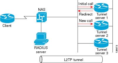
L2TP Redirect Scenario
When tunnel server 1 answers the initial call, SGBP bidding is performed by all stack group members to determine which device owns the call. If the call is owned by a different tunnel server, such as tunnel server 2, the call must be passed from tunnel server 1 to the owner.
In a traditional multihop SGBP deployment, tunnel server 1 would establish an L2F or L2TP tunnel to to tunnel server 2 and forward the call over that tunnel.
With L2TP redirect enabled, instead of establishing a new tunnel to tunnel server 2, tunnel server 1 sends a redirect message to the NAS informing it that tunnel server 2 actually owns the call. The NAS then tears down the initial connection to tunnel server 1 and establishes a new L2TP tunnel directly to tunnel server 2.
Tunnel Switching Using Multihop VPDN
Multihop VPDN can be used to configure a device as a tunnel switch. A tunnel switch acts as both a NAS and a tunnel server, receiving packets from an incoming VPDN tunnel and sending them out over an outgoing VPDN tunnel. Tunnel switch configurations can be used between ISPs to provide wholesale VPDN services. A VPDN tunnel switch can forward L2TP, L2F, or Point-to-Point Tunneling Protocol (PPTP) sessions.
In an L2TP or L2F tunnel switching deployment, the tunnel endpoints are considered the originating NAS and the terminating tunnel server. The tunnel switch is not considered a tunnel endpoint.
In a PPTP tunnel switching deployment, the tunnel endpoints are considered the originating client device and the terminating tunnel server. The tunnel switch is not considered a tunnel endpoint.
Figure 22 shows a network scenario using a basic L2TP tunnel switching deployment.
Figure 22 Tunnel Switching Using Multihop VPDN
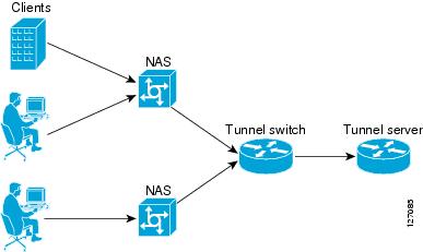
The tunnel switch can be configured to terminate incoming VPDN tunnels from multiple devices, and to initiate outgoing VPDN tunnels to one or more tunnel servers.
Beginning in Cisco IOS Release 12.2(13)T, the Subscriber Service Switch (SSS) framework is supported for VPDN tunnel switching. SSS supports additional Layer 2 protocols, including PPP over Ethernet (PPPoE), PPP over ATM (PPPoA), and generic routing encapsulation (GRE). Configuring SSS for VPDN tunnel switching is optional. SSS profiles increase the scalability of tunnel switching configurations, particularly in multiprotocol environments. For more information on configuring SSS profiles and options, refer to the "Configuring a Cisco Subscriber Service Switch Policy" part of the Cisco IOS Broadband and DSL Configuration Guide, Release 12.4.
How to Configure Multihop VPDN
Perform one of the following procedures to configure Multihop VPDN:
•
•
•
Configuring an MMP Stack Group for Multihop VPDN
Multihop VPDN is required when a VPDN tunnel delivers MLP data to a private network that uses a MMP stack group.
Perform this task on each of the stack group tunnel servers to enable multihop VPDN.
Prerequisites
•
•
•
SUMMARY STEPS
1.
2.
3.
DETAILED STEPS
What to Do Next
•
•
Configuring L2TP Redirect for MMP VPDNs
Enabling L2TP redirect allows a tunnel server in a stack group to send a redirect message to the NAS if it receives a link that belongs to another tunnel server in the stack group. L2TP redirect increases the scalability of MMP deployments. Because all links in a multilink bundle will travel directly to the bundle master after redirection they will experience the same delays and latency, resulting in smoother traffic.
L2TP redirect can be used to load balance both MLP and PPP calls across a stack group.
The following sections contain information on L2TP redirect features:
•
•
•
•
Perform the following tasks to configure L2TP redirect:
•
•
•
•
•
•
•
How L2TP Redirect Works
In a traditional SGBP multihop VPDN deployment, if a stack group member receives a call that belongs to a different stack group member, it forwards the call to the bundle owner over an L2TP or L2F tunnel. When L2TP redirect is configured, instead of forwarding the call to the bundle owner the stack group member will send a redirect message to the NAS. The redirect message includes the IP address or redirect identifier of the bundle owner. The NAS will terminate the initial connection, and initiate a new connection directly to the bundle owner.
For L2TP redirect to function, it must be enabled on both the NAS and the stack group tunnel servers. If the NAS is not configured for L2TP redirect, the tunnel server will forward the call to the bundle owner using traditional multihop technology. This maintains interoperability with non-Cisco devices and Cisco devices running older versions of Cisco IOS software.
In order to redirect the call, the NAS must perform redirect authorization for the bundle owner. If a redirect identifier has been configured on the bundle owner, the NAS uses that identifier to get redirect authorization information. Otherwise, the IP address of the bundle owner must be configured on the NAS.
Number of Redirect Attempts on the NAS
In some cases, a stack group member other than the device that answers the first call from a particular MLP bundle might win the SGBP bid for that call. The call will be redirected to the winning device, but because the call is again the first call from that MLP bundle, another SGBP bid will be triggered. In some rare instances this behavior may result in the initial call being passed from one stack group member to another as different devices win the bid each time.
By default, the NAS will redirect a particular call only three times, preventing excessive redirects. The number of redirect attempts the NAS will make can be configured to meet the needs of a particular network deployment. Once the NAS has redirected a call the configured number of times it will refuse further redirection requests, and traditional multihop forwarding will occur on the stack group.
Load Balancing Calls Using L2TP Redirect
Enabling L2TP redirect allows load balancing of calls to be performed by the stack group rather than the NAS. The stack group tunnel servers bid for each link that comes in, and those tunnel servers with the lightest load will win the bid and become the bundle owner. The managing of bids in this manner results in an even load distribution of sessions among a stack of tunnel servers.
L2TP redirect can also be used to load balance all L2TP PPP calls (not just MLP calls) across a stack group. All the NASs for a particular domain can point to a primary contact tunnel server. This primary tunnel server must have SGBP and the sgbp ppp-forward command configured to force it to issue a mastership query to the stack group for every PPP link. As when performing MLP load balancing, the stack group tunnel servers bid for each link that comes in, and those tunnel servers with the lightest load will win the bids. The primary tunnel server may not actually terminate any sessions; it may simply issue the mastership query, collects the bids, choose the highest one, and redirect the originating NAS to that tunnel server. For more information on PPP configurations, see the "PPP Configuration" part of the Cisco IOS Dial Technologies Configuration Guide, Release 12.4.
Redirect Identifier
The redirect identifier is an optional configuration that simplifies the task of configuring NASs to perform L2TP redirects. If the redirect identifier is not configured, the IP address of every tunnel server in the stack group must be configured with the initiate-to command on each NAS.
The redirect identifier allows new stack group members to be added without the need to update the NAS configuration with their IP addresses. With the redirect identifier configured, a new stack group member can be added and given the same redirect identifier as the rest of the stack group. If stack group members have different authorization information, unique redirect identifiers must be configured.
The redirect identifier can also be configured on a remote RADIUS server, rather than directly on the NAS. The RADIUS server can update multiple NASs with the redirect identifier information, avoiding the requirement to configure the redirect identifier on each NAS.
Redirect Source
The redirect source is an optional configuration that allows a stack group member to advertise a public IP address for L2TP redirection, rather than the IP address used for SGBP bidding. Often a stack group will use private IP addresses for stack group bidding, and these IP addresses will not be reachable by the NAS. Configuring a public IP address as the redirect source allows a stack group member to inform the NAS of the reachable IP address of another stack group member in the redirect request.
Prerequisites for Configuring L2TP Redirect
•
•
•
•
•
Restrictions for Configuring L2TP Redirect
•
•
Enabling L2TP Redirect
For the redirection of calls to occur, L2TP redirect must be enabled on the NAS and on each participating tunnel server.
Perform this task to enable L2TP redirect on all participating devices and to optionally set the number of allowed redirect attempts on the NAS.
SUMMARY STEPS
1.
2.
3.
4.
DETAILED STEPS
What to Do Next
You must perform the task in the "Enabling Multihop VPDN on the NAS" section.
Enabling Multihop VPDN on the NAS
Because redirected packets will pass through multiple VPDN tunnels, multihop must be enabled on the NAS for L2TP redirect to function.
Perform this task on the NAS to enable multihop VPDN.
SUMMARY STEPS
1.
2.
3.
DETAILED STEPS
What to Do Next
•
–
–
•
•
Configuring the Redirect Identifier on the NAS
The L2TP redirect identifier is an optional configuration that simplifies the task of configuring the NAS for L2TP redirect. The redirect identifier can be configured directly on the NAS, or on the remote RADIUS server. Configuring the redirect identifier on the remote RADIUS server allows it to be propagated to multiple NASs without having to configure each NAS directly.
Perform this task to configure the redirect identifier directly on the NAS.
To configure the redirect identifier on the RADIUS server, perform the task in the "Configuring the Redirect Identifier on the RADIUS Server" section instead.
SUMMARY STEPS
1.
2.
3.
4.
DETAILED STEPS
What to Do Next
You must perform the task in the "Configuring the Redirect Identifier on the Stack Group Tunnel Servers" section.
Configuring the Redirect Identifier on the RADIUS Server
The L2TP redirect identifier is an optional configuration that simplifies the task of configuring the NAS for L2TP redirect. The redirect identifier can be configured directly on the NAS, or on the remote RADIUS server. Configuring the redirect identifier on the remote RADIUS server allows it to be propagated to multiple NASs without having to configure each one.
Perform this task to configure the redirect identifier in the RADIUS server profile.
To configure the redirect identifier directly on a NAS, perform the task in the "Configuring the Redirect Identifier on the NAS" section instead.
SUMMARY STEPS
1.
DETAILED STEPS
What to Do Next
You must perform the task in the "Configuring the Redirect Identifier on the Stack Group Tunnel Servers" section.
Configuring the Redirect Identifier on the Stack Group Tunnel Servers
The redirect identifier is an optional configuration that simplifies the task of configuring the NAS for L2TP redirect. The redirect identifier must be configured on each member of the stack group.
Perform this task on each stack group tunnel server to configure the redirect identifier.
SUMMARY STEPS
1.
2.
3.
DETAILED STEPS
What to Do Next
•
•
Configuring the Redirect Source on the Stack Group Tunnel Servers
The redirect source is an optional configuration that allows a stack group member to advertise a public IP address for L2TP redirect, rather than the default IP address. The default IP address is that used for SGBP bidding. If your stack group uses private IP addresses for SGBP bidding, you must configure the redirect source for each tunnel server in the stack. Otherwise the NAS will be redirected to the default IP address, which will be unreachable.
Perform this task on each stack group tunnel server to configure the redirect source.
SUMMARY STEPS
1.
2.
3.
DETAILED STEPS
What to Do Next
You may perform the optional task in the "Monitoring L2TP Redirect Configurations" section.
Monitoring L2TP Redirect Configurations
The number of L2TP sessions that were redirected or forwarded using traditional multihop technology can be monitored. Statistics are maintained on both the NAS and the tunnel servers.
Perform the following task on the NAS or a tunnel server to examine L2TP redirect statistics.
SUMMARY STEPS
1.
2.
3.
DETAILED STEPS
Step 1
Enter this command to enable privileged EXEC mode. Enter your password if prompted:
Router> enableStep 2
Enter this command to display statistics for all L2TP call redirects and forwards. The display shown in this example is from a tunnel server that redirected four calls using L2TP redirect, and forwarded two calls using traditional multihop VPDN.
Router# show vpdn redirect`vpdn redirection enabled'`sessions redirected as access concentrator: 4'`sessions redirected as network server: 0'`sessions forwarded: 2'Step 3
Enter this command to clear the counters for the show vpdn redirect command.
Router# clear vpdn redirect
What to Do Next
You may perform any of the relevant optional tasks in the "Configuring Additional VPDN Features" and "VPDN Tunnel Management" modules.
Configuring a Multihop Tunnel Switch
Multihop VPDN can be used to configure a device as a tunnel switch. A tunnel switch acts as both a NAS and a tunnel server, and must be configured with both a NAS VPDN group and a tunnel server VPDN group.
Beginning in Cisco IOS Release 12.2(13)T, tunnel switching using the SSS infrastructure is supported. SSS allows L2TP, L2F, PPTP, PPPoE, PPPoA, GRE, and general packet radio service (GPRS) sessions to be switched over virtual links using a tunnel switch. SSS configurations are not required for tunnel switching data over L2TP, L2F, or PPTP tunnels, but SSS increases the scalability of tunnel switching deployments. For more information on configuring SSS, refer to the "Configuring a Cisco Subscriber Service Switch Policy" part of the Cisco IOS Broadband and DSL Configuration Guide, Release 12.4.
A multihop VPDN tunnel switch can be configured to forward L2TP, L2F, or PPTP tunnels.
Perform the following tasks to configure a device as a multihop VPDN tunnel switch:
•
•
•
Prerequisites for Configuring a Multihop Tunnel Switch
•
•
Restrictions for Configuring a Multihop Tunnel Switch
Tunnel switching based on dialed number identification service (DNIS) numbers is supported only in Cisco IOS Release 12.2(13)T, Cisco IOS Release 12.2(28)SB, and later releases.
Tunnel switching based on multihop hostnames is supported only in Cisco IOS Release 12.2(13)T and later releases.
Enabling Multihop VPDN on the Tunnel Switch
In tunnel switching deployments, packets must traverse multiple tunnels. Multihop VPDN must be enabled on the tunnel switch for the deployment to function.
Perform this task on the tunnel switch to enable multihop VPDN.
SUMMARY STEPS
1.
2.
3.
DETAILED STEPS
What to Do Next
You must perform the task in the "Configuring the Multihop Tunnel Switch to Terminate Incoming VPDN Tunnels" section.
Configuring the Multihop Tunnel Switch to Terminate Incoming VPDN Tunnels
A tunnel switch must be configured as a tunnel server, allowing it to terminate incoming VPDN tunnels.
Perform this task to configure the tunnel switch to terminate incoming VPDN tunnels. You may configure a tunnel switch to terminate tunnels from multiple devices.
SUMMARY STEPS
1.
2.
3.
4.
5.
6.
7.
8.
9.
DETAILED STEPS
What to Do Next
You must perform the task in the "Configuring the Multihop Tunnel Switch to Initiate Outgoing VPDN Tunnels" section.
Configuring the Multihop Tunnel Switch to Initiate Outgoing VPDN Tunnels
A tunnel switch must be configured as a NAS, allowing it to initiate outgoing VPDN tunnels.
Perform this task to configure the tunnel switch to initiate outgoing VPDN tunnels. You may configure a tunnel switch to initiate tunnels to multiple devices.
SUMMARY STEPS
1.
2.
3.
4.
5.
6.
7.
or
dnis {dnis-number | dnis-group-name}
or
multihop-hostname ingress-tunnel-name8.
9.
DETAILED STEPS
Step 1
enable
Example:Router> enable
Enables privileged EXEC mode.
•
Step 2
configure terminal
Example:Router# configure terminal
Enters global configuration mode.
Step 3
Router(config)# vpdn-group 1
Creates a VPDN group and enters VPDN group configuration mode.
Step 4
Router(config-vpdn)# description myvpdngroup
(Optional) Adds a description to a VPDN group.
Step 5
request-dialin
Example:Router(config-vpdn)# request-dialinConfigures a tunnel switch to request the establishment of a tunnel to a tunnel server, creates a request-dialin VPDN subgroup, and enters VPDN request dial-in subgroup configuration mode.
Step 6
protocol {any | l2f | l2tp | pptp}
Example:Router(config-vpdn-req-in)# protocol l2tp
Specifies the Layer 2 protocol that the VPDN group will use.
•
Step 7
or
dnis {dnis-number | dnis-group-name}
or
multihop-hostname ingress-tunnel-name
Example:Router(config-vpdn-req-in)# domain company.comor
Example:Router(config-vpdn-req-in)# dnis 5687
or
Example:Router(config-vpdn-req-in)# multihop-hostname nas1Requests that PPP calls from a specific domain name be tunneled.
or
(Cisco IOS Release 12.2(13)T, Cisco IOS Release 12.2(28)SB, or later releases) Requests that PPP calls from a specific DNIS number or DNIS group be tunneled.
or
(Cisco IOS Release 12.2(13)T or later) Enables the tunnel switch to initiate a tunnel based on the NAS host name or the ingress tunnel ID.
Note
Step 8
exit
Example:Router(config-vpdn-req-in)# exit
Exits to VPDN group configuration mode.
Step 9
initiate-to ip ip-address [limit limit-number] [priority priority-number]
Example:Router(config-vpdn)# initiate-to ip 10.1.1.1 limit 12Specifies an IP address that will be used for Layer 2 tunneling.
•
–
–
Note
•
What to Do Next
You may perform any of the relevant optional tasks in the "Configuring Additional VPDN Features" and "VPDN Tunnel Management" modules.
Configuration Examples for Multihop VPDN
This section contains the following configuration examples:
•
•
•
•
•
•
Configuring Multihop VPDN on an MMP Stack Group: Example
The following example configures a stack group and a NAS for dial-in L2F VPDN tunneling with multihop VPDN enabled:
Tunnel Server A Configuration
!Enable VPDNvpdn enable!!Enable multihop VPDNvpdn multihop!!Configure the tunnel server to accept L2F tunnels from the NASvpdn-group group1accept-dialinprotocol l2fvirtual-template 1!terminate-from 172.18.32.139!!Configure the tunnel server as a stack group memberusername user1 password mypasswordsgbp group mystacksgbp member tunnelserverb 10.1.1.2sgbp member tunnelserverc 10.1.1.3Tunnel Server B Configuration
!Enable VPDNvpdn enable!!Enable multihop VPDNvpdn multihop!!Configure the tunnel server to accept L2F tunnels from the NASvpdn-group group1accept-dialinprotocol l2fvirtual-template 1!terminate-from 172.18.32.139!!Configure the tunnel server as a stack group memberusername user1 password mypasswordsgbp group mystacksgbp member tunnelservera 10.1.1.1sgbp member tunnelserverc 10.1.1.3Tunnel Server C Configuration
!Enable VPDNvpdn enable!!Enable multihop VPDNvpdn multihop!!Configure the tunnel server to accept L2F tunnels from the NASvpdn-group group1accept-dialinprotocol l2fvirtual-template 1!terminate-from 172.18.32.139!!Configure the tunnel server as a stack group memberusername user1 password mypasswordsgbp group mystacksgbp member tunnelservera 10.1.1.1sgbp member tunnelserverb 10.1.1.2NAS Configuration
!Enable VPDNvpdn enable!!Configure the NAS to initiate L2F tunnelsvpdn-group group1request-dialinprotocol l2fdomain cisco.com!!Configure the NAS with the IP address of each tunnel server in the stack groupinitiate-to ip 10.1.1.1initiate-to ip 10.1.1.2initiate-to ip 10.1.1.3Configuring L2TP Redirect: Example
The following example configures a stack group and a NAS for dial-in L2TP VPDN tunneling and enables basic L2TP redirect:
Tunnel Server A Configuration
!Enable VPDNvpdn enable!!Enable multihop to ensure interoperability with devices that are not capable of !performing L2TP redirect.vpdn multihop!!Enable L2TP redirectvpdn redirect!!Configure the tunnel server to accept L2TP tunnels from the NASvpdn-group group1accept-dialinprotocol l2tpvirtual-template 1!terminate-from 172.18.32.139!!Configure the tunnel server as a stack group memberusername user1 password mypasswordsgbp group mystacksgbp member tunnelserverb 10.1.1.2sgbp member tunnelserverc 10.1.1.3Tunnel Server B Configuration
!Enable VPDNvpdn enable!!Enable multihop to ensure interoperability with devices that are not capable of !performing L2TP redirect.vpdn multihop!!Enable L2TP redirectvpdn redirect!!Configure the tunnel server to accept L2TP tunnels from the NASvpdn-group group1accept-dialinprotocol l2tpvirtual-template 1!terminate-from 172.18.32.139!!Configure the tunnel server as a stack group memberusername user1 password mypasswordsgbp group mystacksgbp member tunnelservera 10.1.1.1sgbp member tunnelserverc 10.1.1.3Tunnel Server C Configuration
!Enable VPDNvpdn enable!!Enable multihop to ensure interoperability with devices that are not capable of !performing L2TP redirect.vpdn multihop!!Enable L2TP redirectvpdn redirect!!Configure the tunnel server to accept L2TP tunnels from the NASvpdn-group group1accept-dialinprotocol l2tpvirtual-template 1!terminate-from 172.18.32.139!!Configure the tunnel server as a stack group memberusername user1 password mypasswordsgbp group mystacksgbp member tunnelservera 10.1.1.1sgbp member tunnelserverb 10.1.1.2NAS Configuration
!Enable VPDNvpdn enable!!Enable multihop VPDNvpdn multihop!!Enable L2TP redirectvpdn redirect!!Configure the NAS to initiate L2TP tunnelsvpdn-group group1request-dialinprotocol l2tpdomain cisco.com!!Configure the NAS with the IP address of each tunnel server in the stack groupinitiate-to ip 10.1.1.1initiate-to ip 10.1.1.2initiate-to ip 10.1.1.3Configuring L2TP Redirect with a Redirect Identifier: Example
The following example configures the NAS and stack group tunnel servers for L2TP redirect using a redirect identifier:
Tunnel Server A Configuration
!Enable VPDNvpdn enable!!Enable multihop to ensure interoperability with devices that are not capable of !performing L2TP redirect.vpdn multihop!!Enable L2TP redirectvpdn redirect!!Configure the tunnel server to accept L2TP tunnels from the NASvpdn-group group1accept-dialinprotocol l2tpvirtual-template 1!terminate-from 172.18.32.139!!Configure the tunnel server as a stack group memberusername user1 password mypasswordsgbp group mystacksgbp member tunnelserverb 10.1.1.2sgbp member tunnelserverc 10.1.1.3!!Configure the redirect identifiervpdn redirect identifier stack1Tunnel Server B Configuration
!Enable VPDNvpdn enable!!Enable multihop to ensure interoperability with devices that are not capable of !performing L2TP redirect.vpdn multihop!!Enable L2TP redirectvpdn redirect!!Configure the tunnel server to accept L2TP tunnels from the NASvpdn-group group1accept-dialinprotocol l2tpvirtual-template 1!terminate-from 172.18.32.139!!Configure the tunnel server as a stack group memberusername user1 password mypasswordsgbp group mystacksgbp member tunnelservera 10.1.1.1sgbp member tunnelserverc 10.1.1.3!!Configure the redirect identifiervpdn redirect identifier stack1Tunnel Server C Configuration
!Enable VPDNvpdn enable!!Enable multihop to ensure interoperability with devices that are not capable of !performing L2TP redirect.vpdn multihop!!Enable L2TP redirectvpdn redirect!!Configure the tunnel server to accept L2TP tunnels from the NASvpdn-group group1accept-dialinprotocol l2tpvirtual-template 1!terminate-from 172.18.32.139!!Configure the tunnel server as a stack group memberusername user1 password mypasswordsgbp group mystacksgbp member tunnelservera 10.1.1.1sgbp member tunnelserverb 10.1.1.2!!Configure the redirect identifiervpdn redirect identifier stack1NAS Configuration
!Enable VPDNvpdn enable!!Enable L2TP redirectvpdn redirect!!Configure the NAS to initiate L2TP tunnelsvpdn-group group1request-dialinprotocol l2tpdomain cisco.com!!Configure the NAS with the redirect identifierredirect identifier stack1Configuring Redirect Identifiers on the RADIUS Server: Example
cisco.com Password = "cisco"Tunnel-Type = :0:L2TP,Tunnel-Medium-Type = :0:IP,Tunnel-Server-Endpoint = :0:"10.1.1.1",Cisco:Cisco-Avpair = :0:"vpdn:vpdn-redirect-id=ts1",Tunnel-Type = :1:L2TP,Tunnel-Medium-Type = :1:IP,Tunnel-Server-Endpoint = :1:"10.1.1.2",Cisco:Cisco-Avpair = :1:"vpdn:vpdn-redirect-id=ts2"Tunnel-Type = :2:L2TP,Tunnel-Medium-Type = :1:IP,Tunnel-Server-Endpoint = :1:"10.1.1.3",Cisco:Cisco-Avpair = :1:"vpdn:vpdn-redirect-id=ts3"Configuring the Redirect Source on a Stack Group Tunnel Server: Example
The following example configures one member of a stack group to accept dial-in L2TP VPDN tunnels and enables L2TP redirect using a redirect source IP address:
!Enable VPDNvpdn enable!!Enable multihop to ensure interoperability with devices that are not capable of !performing L2TP redirect.vpdn multihop!!Enable L2TP redirectvpdn redirect!!Configure the tunnel server to accept L2TP tunnelsvpdn-group group1accept-dialinprotocol l2tpvirtual-template 1!terminate-from 172.18.32.139!!Configure the tunnel server as a stack group memberusername user1 password mypasswordsgbp group stack1sgbp member tunnelserverb 10.1.1.2sgbp member tunnelserverc 10.1.1.3!!Configure the redirect sourcevpdn redirect source 172.23.1.1Configuring Multihop VPDN Tunnel Switching: Example
The following example configures a NAS, tunnel switch, and tunnel server to establish a multihop VPDN tunnel using L2TP:
NAS Configuration
! Configure the NAS to initiate VPDN dial-in sessions to the tunnel switchvpdn-group 1request-dialinprotocol l2tpdomain cisco.com!initiate-to ip 172.22.66.25local name ISP-NASTunnel Switch Configuration
!Enable VPDNvpdn enable!!Enable multihopvpdn multihop!
! Configure the tunnel switch to use the multihop hostname in the authentication search.
vpdn search-order multihop-hostname domain dnis
!
! Configure the tunnel switch to accept dial-in sessions from the NASvpdn-group tunnelinaccept-dialinprotocol l2tpvirtual-template 1!terminate-from hostname ISP-NASlocal name ISP-Sw!! Configure the tunnel switch to initiate VPDN dial-in sessions to the tunnel servervpdn-group tunneloutrequest-dialinprotocol l2tpmultihop-hostname ISP-NAS!initiate-to ip 10.2.2.2local name ISP-SwTunnel Server Configuration
! Configure the tunnel server to accept dial-in sessions from the NASvpdn-group 1accept-dialinprotocol l2tpvirtual-template 1!terminate-from hostname ISP-Swlocal name ENT-TSWhere to Go Next
You may perform any of the relevant optional tasks in the "Configuring Additional VPDN Features" and "VPDN Tunnel Management" modules.
Additional References
The following sections provide references related to configuring multihop VPDN.
Related Documents
VPDN technology overview
VPDN commands: complete command syntax, command mode, defaults, usage guidelines, and examples
Cisco IOS VPDN Command Reference, Release 12.4T
Information about Multichassis Multilink PPP
"Implementing Multichassis Multilink PPP" module in the Cisco IOS Dial Technologies Configuration Guide, Release 12.4.
Information about virtual templates
The "Configuring Virtual Template Interfaces" chapter of the Cisco IOS Dial Technologies Configuration Guide, Release 12.4.
Dial Technologies commands: complete command syntax, command mode, defaults, usage guidelines, and examples
Cisco IOS Dial Technologies Command Reference, Release 12.4T
Information about SSS
"Configuring a Cisco Subscriber Service Switch Policy" part of the Cisco IOS Broadband and DSL Configuration Guide, Release 12.4.
Broadband access aggregation and DSL command: complete command syntax, command mode, defaults, usage guidelines, and examples
Cisco IOS Broadband Access Aggregation and DSL Command Reference, Release 12.4T
Standards
MIBs
None
To locate and download MIBs for selected platforms, Cisco IOS releases, and feature sets, use Cisco MIB Locator found at the following URL:
RFCs
RFC 2341
Cisco Layer Two Forwarding (Protocol) "L2F"
RFC 2661
Layer Two Tunneling Protocol "L2TP"
Technical Assistance
Feature Information for Multihop VPDN
Table 9 lists the features in this module and provides links to specific configuration information. Only features that were introduced or modified in Cisco IOS Release 12.2(1) or a later release appear in the table.
Not all commands may be available in your Cisco IOS software release. For details on when support for a specific command was introduced, see the command reference documentation.
For information on a feature in this technology that is not documented here, see the "VPDN Features Roadmap."
Cisco IOS software images are specific to a Cisco IOS software release, a feature set, and a platform. Use Cisco Feature Navigator to find information about platform support and Cisco IOS software image support. Access Cisco Feature Navigator at http://www.cisco.com/go/fn. You must have an account on Cisco.com. If you do not have an account or have forgotten your username or password, click Cancel at the login dialog box and follow the instructions that appear.

Note
Table 9 Feature Information for Multihop VPDN
L2TP Redirect
12.2(13)T
12.2(28)SBThis feature allows a tunnel server participating in SGBP to send a redirect message to the NAS if another stack group member wins the SGBP bid. The NAS will then reinitiate the call to the newly redirected tunnel server.
The following sections provide information about this feature:
•
•
The following commands were introduced by this feature:
clear vpdn redirect, show vpdn redirect, vpdn redirect, vpdn redirect attempts, vpdn redirect identifier, vpdn redirect source.
Subscriber Service Switch
12.2(13)T
This feature provides flexibility on where and how many subscribers are connected to available services and how those services are defined. The primary focus of SSS is to direct PPP from one point to another using a Layer 2 subscriber policy. The policy will manage tunneling of PPP in a policy-based bridging fashion.
The following sections provide partial information about this feature:
•
•
The following VPDN commands were introduced or modified by this feature:
multihop-hostname, vpdn search-order.
Additional documentation for SSS can be found in the Configuring a Cisco Subscriber Service Switch Policy" section of the Cisco IOS Broadband and DSL Configuration Guide, Release 12.4.
VPDN Multihop by DNIS
12.2(13)T
12.2(28)SBThis feature allows DNIS-based multihop capability for VPDNs.
The following sections provide information about this feature:
•
•
The following commands were introduced or modified by this feature:
vpdn multihop, vpdn search-order.

© 2006 Cisco Systems, Inc. All rights reserved.
This module first published October 31, 2005. Last updated February 28, 2006.
 Feedback