NM-AIC-64, Contact Closure Network Module
Available Languages
Table Of Contents
NM-AIC-64, Contact Closure Network Module
Configuring an Analog Alarm as an Analog Monitoring Voltage
Configuring an Analog Alarm as a Discrete Monitoring Current
Configuring an Analog Alarm as a Discrete Monitoring Voltage
Configuring an Analog Alarm to Act Like a Discrete Alarm (Minimal Configuration Method)
Supported Standards, MIBs, and RFCs
Entering Alarm Configuration Mode and Configuring the AIC IP Address
Configuring the IP Route to the AIC
Configuring the NOC IP Address
Programming the Analog Contact Points
Programming the Discrete Contact Points
Configuring the AIC IP Address
Configuring IP Route to the AIC
Without an Unnumbered IP Address
AIC CLI Configuration for Alarms
Analog Alarm Monitoring Current
Analog Alarm Monitoring Current Configured as a Discrete
NM-AIC-64, Contact Closure Network Module
Feature History
12.2(2)XG
This feature was introduced on the Cisco 2600 series and Cisco 3600 series platforms.
This feature module describes the software support for the Network Module-Alarm Interface Controller-64, Contact Closure Network Module or NM-AIC-64, Contact Closure Network Module. It includes information on the benefits of the new feature, supported platforms, related documents, and so on.
This document includes the following sections:
Supported Standards, MIBs, and RFCs
Feature Overview
The AIC NM is an optional card that expands network management capabilities for customer-defined alarms. The AIC has its own CPU that communicates with the router and external media through serial communication channels. The AIC reduces service provider and enterprise operating costs by providing a flexible, low-cost network solution for migrating existing data communications networks (DCNs) to IP-based DCNs. The AIC provides its users with a single "box" solution because it can be configured in the same router along with other Operation, Alarm, Maintenance, and Provisioning (OAM&P) interfaces.
More than one AIC can be installed per router. For example, a Cisco 3662 can have up to five AICs, and its sixth NM slot can be used for router communication. The Cisco 3640 can have up to three AICs, with the fourth NM slot reserved for communication, and so forth.
The AIC provides a total of 64 alarm inputs. Eight of the 64 point are software configurable for measuring either analog inputs or discrete inputs. The remaining 56 points are fixed to measure discrete points only. The AIC also provides 16 control relay outputs.
The discrete alarm input can be activated through ground or negative battery input. The negative battery range is -36V to -72V. The analog alarm is software configurable for either DC voltage or current. It can measure voltage from -60 to 60V or current from 0 to 20mA, but the configurable range is 4 mA to 20mA. The standard 16 control relays can be configured to turn on or turn off an external device.
The AIC's 64 input contact points can control and monitor network elements and other non-intelligent interfaces, permitting the detection and report of alarms such as the following:
•
Network element alarm states
•
•
•
•
When an event occurs, such as a door alarm or an open gate, the AIC maps the simple discrete and analog alarms to pre programmed intelligent messages and transports the messages to destinations in the IP network, typically to a Network Operations Center (NOC). These messages are generated either in Transaction Language 1 (TL1) or in Simple Network Management Protocol (SNMP), which are used by a NOC's Operations Support System (OSS).
When the AIC is incorporated into the Cisco's DCN solution platforms, all the AIC's contact-closure alarms are routed and reported through the same network and systems as the intelligent network elements (NEs). This facilitates continued use of the existing OSS and its associated networks. A Cisco router with an AIC sends TL1 or SNMP messages to the OSS autonomously or in response to TL1 or SNMP commands from the OSS, as shown in Figure 1. TL1 supports two sessions, with the port numbers 5011 and 5012, respectively and SNMP supports four sessions.
Figure 1 TL1 and SNMP Message Flow in a DCN Application
Serial Communication Channels
As illustrated in Figure 2, the AIC has two serial communications channels that provide different types of interfaces to the Cisco IOS:
•
•
Figure 2 OS Boundary into the AIC
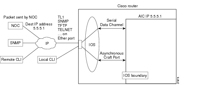
Serial Data Channel
The serial data channel supports all TCP/IP traffic to and from the AIC. This includes communication over IP with NOCs and data centers. The channel consists of one physical interface that provides support for the following applications:
•
•
•
•
The Cisco IOS assigns an IP address to the AIC for use by the serial data channel. To route traffic, the serial data channel uses IP over synchronous High-Level Data Link Control (HDLC). All IP packets coming to the Cisco router with a destination IP address that matches the AIC's IP address are forwarded to the serial data channel using IP over HDLC.
Asynchronous Craft Port
The asynchronous craft port supports Telnet to the AIC's port number. This Telnet method, called local-CLI, is useful for debugging when remote Telnet to the AIC's IP address (remote-CLI) is not applicable. For more information see the "Configuring the NOC IP Address" section.
The asynchronous craft port also supports an AIC boot sequence, similar to the ROM monitor in Cisco IOS, which allows the user to recover from a corrupted software image or configuration. See the "Override" section.
Configuring the AIC
From a top-level view, AIC configuration involves assigning an IP address to the AIC using Cisco IOS commands and setting up alarm configurations with either TL1 or the AIC command-line interface (CLI). The flexible TL1 and AIC CLI permit a broad range of alarm configuration scenarios. The following are examples of four possible alarm configurations that can be programmed with the AIC CLI:
Configuring a Discrete Alarm
enableconfig terminalalarm 1description "west door"normally closeddescription normal "door closed"description alarm "door open"level 2exitConfiguring an Analog Alarm as an Analog Monitoring Voltage
enableconfig terminalalarm 57description "tank level"description normal "full"description low "low"description low-low "empty"analog voltage 2.5 30 60 60exitConfiguring an Analog Alarm as a Discrete Monitoring Current
enableconfig terminalalarm 58description "east door"discrete current-loop 0.0 3.2 5.9exitConfiguring an Analog Alarm as a Discrete Monitoring Voltage
enableconfig terminalalarm 58description "backup battery"discrete voltage 9.0 highexitConfiguring an Analog Alarm to Act Like a Discrete Alarm (Minimal Configuration Method)
enableconfig terminalalarm 59discreteexitBenefits
Increased Functionality and Versatility
The AIC increases functionality and versatility of the Cisco 2600 series, Cisco 3640, Cisco 3660, and Cisco 3662, giving service providers and enterprises enhanced communications and connections between the OSS and the NOC.
Low Cost Migration to Cost-Effective Technology
The AIC provides a flexible, low-cost network solution for service providers and enterprises to migrate existing DCNs to IP-based DCNs and to bridge traditional operations networks to a more cost-efficient, next generation, IP-based operations network.
Efficient, Single "Box" Solution
The AIC provides discrete and analog alarms and initiated surveillance messages for central office and branch office network equipment (with non-intelligent interfaces) within the Cisco DCN solution products. By providing the contact closure network module in the same "box" as all the other OAM&P intelligent interfaces, customers benefit from the cost savings of a single-box solution that facilitates further DCN consolidation.
Streamlines Management and Implementation
The AIC's single box solution simplifies service providers' network management processes. It also streamlines the installation of a solution for contact closure alarms because it reduces the number of external elements required to carry out such a function. This is especially beneficial to competitive local exchange carriers (CLECs) entering into a central office co-location situation where space is at a premium.
Restrictions
•
•
Related Documents
Other Documents
•
•
Supported Platforms
•
•
Platform Support Through Feature Navigator
Cisco IOS software is packaged in feature sets that support specific platforms. To get updated information regarding platform support for this feature, access Feature Navigator. Feature Navigator dynamically updates the list of supported platforms as new platform support is added for the feature.
Feature Navigator is a web-based tool that enables you to quickly determine which Cisco IOS software images support a specific set of features and which features are supported in a specific Cisco IOS image.
To access Feature Navigator, you must have an account on Cisco.com. If you have forgotten or lost your account information, send a blank e-mail to cco-locksmith@cisco.com. An automatic check will verify that your e-mail address is registered with Cisco.com. If the check is successful, account details with a new random password will be e-mailed to you. Qualified users can establish an account on Cisco.com by following the directions at http://www.cisco.com/register.
Feature Navigator is updated when major Cisco IOS software releases and technology releases occur. As of May 2001, Feature Navigator supports M, T, E, S, and ST releases. You can access Feature Navigator at the following URL:
•
Supported Standards, MIBs, and RFCs
Standards
No new or modified standards are supported by this feature.
MIBs
The AIC introduces a new MIB called CISCO-AIC-MIB. To support the AIC, an AIC object type and AIC ID were added to the following MIBs:
•
•
To obtain lists of supported MIBs by platform and Cisco IOS release, and to download MIB modules, go to the Cisco MIB website on Cisco.com at the following URL:
http://www.cisco.com/public/sw-center/netmgmt/cmtk/mibs.shtml
RFCs
No new or modified RFCs are supported by this feature.
Configuration Tasks
See the following sections for configuration tasks for the AIC feature:
•
–
–
•
•
Configuring the AIC
Cisco IOS commands are used for configuring the AIC IP address and the IP routing to the AIC NM. After the IP address and the IP routing are set, alarm configurations can then be set up with either TL1 or the AIC command-line interface. See Configuring the NOC IP Address or Configuring Alarms for more information
The following sections describe how to configure the AIC IP address and the IP Routing to the AIC NM:
Entering Alarm Configuration Mode and Configuring the AIC IP Address
Enter alarm configuration mode and configure the AIC IP address, beginning in privileged EXEC mode:
Table 1 Configuring IP Routing to the AIC with an Unnumbered IP Address
Configuring the IP Route to the AIC
There are many ways to configure IP routing to the AIC. Below are two methods. The first method, shown in Table 2, uses an unnumbered IP address. It is used when an administrator wants to assign an IP address that is already known to the router, such as an address that is one of the addresses in the subnet of a FastEthernet IP address.
The second method, shown in Table 3, does not use an unnumbered IP address and is used when there is a subnet available to the serial interface and to the AIC. Usually this subnet is small with a subnet mask such as 255.255.255.252.
Configure IP routing to the AIC, beginning in global configuration mode:
Table 2 Configuring IP Routing to the AIC with an Unnumbered IP Address
Table 3 Configuring IP Routing to the AIC without an Unnumbered IP Address
Accessing the AIC
Remote-CLI and local-CLI are the two methods for accessing the AIC:
•
telnet 10.5.5.2•
telnet 10.2.130.105 2001where 10.2.130.105 is the router's IP address and 2001 is on slot 0 of the AIC.
The AIC's TCP port number depends on the slot number in which the AIC is installed. As shown in Table 4, the Cisco IOS software reserves the first line of each slot for the asynchronous craft port.
Table 4 TCP Port Number Allocation for the AIC on the Cisco 2600 and Cisco 3600 Series
Configuring the NOC IP Address
Configure up to four NOC IP addresses to which the AIC will send SNMP messages, beginning in global configuration mode:

Note
The aic command-line prompt indicates that either TL1 or AIC CLI commands must be used.
Configuring Alarms
After the AIC and NOC IP addresses have been configured, you can the configure alarms by programming the AIC's discrete and analog contact points. These tasks can be performed on-site or by Telneting as described in the "Accessing the AIC" section.
Alarms are configured using either TL1 or AIC CLI. Information about TL1 commands can be found in the Telcordia Technology (formerly Bellcore) document Network Maintenance: Network Element and Transport Surveillance Messages, GR-833-CORE, Issue 5, November 1996. For a reference of security-related commands (ACT-USER and CANC-USER) refer to Telcordia Technology's Operations Applications Messages-Network Element and Network System Security Admin Messages, TR-NWT-000835, Issue 2, January 1993. The following TL1 messages and commands are supported by the AIC:
•
–
–
–
•
–
–
–
–
–
–
–
–
–
–
–
–
–
–
–
–
–
–
The AIC TL1 and its commands are described in the AIC CLI Syntax.
Programming the Analog Contact Points
Alarm points 57 through 64 are analog inputs, which are configurable as discrete inputs. When configured as an analog input, the user must select whether the point is monitoring voltage or current. The user must also define five ranges by selecting four values for a point monitoring voltage or six ranges for a point monitoring current. For current-monitoring points, the lowest and highest values define the range of possible values. (Valid values are from -9999999.9 to 9999999.9.) For voltage-monitoring alarms, the range of possible values is always -60V to 60V. The other four values must be within the defined range, and they partition the range into low-low, low, high, and high-high ranges. Except for the normal range, each range is associated with an alarm condition.
Analog points have four unique alarm states. Each alarm state has its own alarm description string. Only one alarm state per point may be active at any given time. In other words, when a threshold is crossed, the previous alarm state is cleared and the new alarm state is active.
When an analog input is configured as discrete, the user must select whether the point is monitoring voltage or current. Similar to the analog configuration, the user must also select the range of acceptable values for a current-monitoring alarm. (Valid values are from -9999999.9 to 9999999.9.) The voltage range is always -60V to 60V. The user must define the threshold that will cause the alarm condition and whether the normal state of the alarm is the higher or lower range.
Note
analog current-loop 10 13 16 17 20 26
has 16 units between 10 and 26. If the AIC measures 4 mA, then it will factor that the point is registering at the lower boundary. The AIC will interpret 13 as 7 mA, 16 as 10 mA, 17 as 11 mA, 20 as 14 mA, and 26 as the upper boundary, which is 20 mA.
Following are examples:
Point 57 is monitoring ambient temperature of a building and the sensor range is -20 to 75 degrees Celsius. Below 0 degrees is a critical alarm, 0 to 10 degrees is a major alarm, 10 to 35 degrees is the normal range, 35 to 45 degrees is a minor alarm, and above 45 degrees is a major alarm. The configuration for this point follows:
alarm 57analog current-loop -20 0 10 35 45 75level low-low 1level low 2level high 3level high-high 2Point 58 is monitoring a fuel tank level with a resistive sensor. Below -46 volts is a critical alarm, -46 to -40 volts is a minor alarm, and above -40 volts is the normal range. This is a unidirectional alarm, so the high thresholds are set equal to the high bound (since this threshold cannot be crossed). The configuration for this point follows:
alarm 58analog voltage -46 -40 60 60level low-low 1level low 3Point 59 is monitoring a battery bank. Below -42 volts is a critical alarm and above -42 volts is the normal range. The configuration for this point follows:
alarm 59discrete voltage -42 highlevel 1Programming the Discrete Contact Points
The discrete alarms do not require as much programming as the analog alarms. The AIC CLI commands available are the following:
no
Reversal Option
exit
Exits current mode
description
See Alarm Subconfiguration Mode
normally
level
Verifying the IP Address
To verify that the correct AIC IP address and IP route was entered, use the show run command. Below are samples of before-configuration and after-configuration show run outputs:
interface Serial5/0ip unnumbered FastEthernet0/0!ip route 10.2.130.102 255.255.255.255 Serial5/0!alarm-interface 5ip address 10.2.130.102********Before Configuration show run Output*******version 12.1no service single-slot-reload-enableservice timestamps debug uptimeservice timestamps log uptimeno service password-encryption!hostname uut2-3660!logging rate-limit console 10 except errors!ip subnet-zero!!no ip fingerno ip domain-lookup!call rsvp-synccns event-service server!!interface FastEthernet0/0ip address 10.2.130.2 255.255.0.0duplex autospeed autono cdp enable!interface Serial5/0no ip address!ip kerberos source-interface anyip classlessip route 0.0.0.0 0.0.0.0 10.2.0.1ip http server!no cdp run!!dial-peer cor custom!!line con 0exec-timeout 0 0transport input noneline 161no exectransport preferred nonetransport input telnettransport output nonestopbits 1line aux 0line vty 0 4password lablogin!end*****After Configuration show run Output*******version 12.1no service single-slot-reload-enableservice timestamps debug uptimeservice timestamps log uptimeno service password-encryption!hostname uut2-3660!logging rate-limit console 10 except errorsno logging console!ip subnet-zero!
!
no ip fingerno ip domain-lookup!call rsvp-synccns event-service server!interface FastEthernet0/0ip address 10.2.130.2 255.255.0.0duplex autospeed autono cdp enable!interface Serial5/0ip unnumbered FastEthernet0/0!ip kerberos source-interface anyip classlessip route 0.0.0.0 0.0.0.0 10.2.0.1ip route 10.2.130.102 255.255.255.255 Serial5/0ip http server!no cdp run!!alarm-interface 5ip address 10.2.130.102!dial-peer cor custom!!!line con 0exec-timeout 0 0transport input noneline 161no exectransport preferred nonetransport input telnettransport output nonestopbits 1line aux 0line vty 0 4password lablogin!endTroubleshooting Tips
If no alarm messages are sent for an unusually long period of time, ping the AIC address to check for connectivity.
Monitoring and Maintaining
The AIC provides a TFTP client for software upgrade and configuration image transfer. The methods for both actions, as well as how to override the existing software or configuration, are described below.
Software Upgrade
When upgrading software, the AIC must be reset to run the new software. The AIC provides a protected (login required) command for software download. When the user invokes this command with the TFTP server address as a parameter, the AIC connects to the IP address and, via TFTP, retrieves the software image file. After verifying that the software has been transferred successfully, the AIC replaces its running software with the newly downloaded software.
In the case of incompatible versions of IOS and AIC software, the IOS recognizes the difference and displays this information to the user. The user makes the decision whether to upgrade or downgrade either the IOS or AIC software or to take no corrective action.
Configuration Backup
AIC CLI provides commands for storing and restoring configurations. Users can transfer the current configuration of the AIC to or from the TFTP server whose address is given as a parameter to the get config command. When a configuration file is transferred from the server to the AIC, the AIC takes on the new configuration.
The configuration is stored as a list of commands (script) that can be applied to the CLI of an AIC for configuration.
Two other useful commands are get image and put config. Use get image to get a new image, and
put config to back up the configuration to the TFTP server.Backup is not automatic, but the AIC will remind the user, upon logout, to back up the configuration.
Override
In the case that bad software is resident on the AIC or that the configured administrator password is lost, the AIC provides a method for recovering the card. Upon booting, the AIC begins a countdown, visible at the AIC local CLI (Craft Port). If an ASCII character is received on that local CLI channel (DSCC4 channel 2) during this countdown, the AIC enters a mode in which a limited CLI is available. At this limited CLI, available over the Craft Port only, no login is necessary. The user may execute commands for software upgrade and configuration transfer. The new configuration will take effect upon a reset of the AIC card. See reset (AIC) for more information.
After interrupting the countdown, the user will see an "[AIC Boot]:" prompt. From this prompt, the user can enter "?" to see the available commands, "g" to get a new application image, or "d" to delete the current configuration and return to the defaults. (All commands require a carriage return.) In the case of the get command, the user will be prompted for the name of the file, the IP address of the TFTP server, and a confirmation.
Show Commands
The Cisco IOS show command can be used to display AIC configuration settings and the information sent to the IOS by the AIC. The ping command is useful for verifying asynchronous line connectivity.
The following Cisco IOS show command can be used to monitor and maintain alarms:
Router# show alarm-interface [slot-number] {summary}
Displays AIC configuration setting and the information sent to the IOS by the AIC.
A list of the AIC CLI show commands can be found in the "User Mode" section.
Configuration Examples
This section provides the following configuration examples:
•
•
–
–
•
Configuring the AIC IP Address
version 12.2no service single-slot-reload-enableservice tcp-keepalives-inservice tcp-keepalives-outservice timestamps debug uptimeservice timestamps log uptimeno service password-encryption!hostname 3600-top!logging rate-limit console 10 except errors!memory-size iomem 15ip subnet-zero!!no ip fingerno ip domain-lookupip host moe 172.31.10.2ip host mickey 10.1.1.2!no ip dhcp-client network-discoveryframe-relay switchingx25 routing!!call-history-mib max-size 50!interface Ethernet0/0ip address 10.5.37.13 255.255.0.0ip helper-address 223.255.254.254no keepalivehalf-duplex!interface Serial0/0ip address 10.5.5.1 255.255.255.0encapsulation frame-relayno ip mroute-cacheclockrate 500000frame-relay class voice-vcframe-relay traffic-shapingframe-relay map ip 10.5.5.2 990 broadcastframe-relay interface-dlci 990frame-relay intf-type dce!interface Ethernet0/1no ip addresshalf-duplexno cdp enable!interface Serial0/1ip address 10.11.11.1 255.255.255.0encapsulation frame-relayno ip mroute-cacheclockrate 256000frame-relay class voice-vcframe-relay traffic-shapingframe-relay interface-dlci 991frame-relay intf-type dce!interface Serial1/0ip address negotiated!router mobile!ip kerberos source-interface anyip classlessip route 223.255.254.254 255.255.255.255 10.5.0.1ip route 223.255.254.254 255.255.255.255 Ethernet0/0no ip http server!!map-class frame-relay voice-vcframe-relay cir 800000frame-relay bc 512000no frame-relay adaptive-shapingframe-relay fair-queueframe-relay voice bandwidth 500000frame-relay fragment 100frame-relay ip rtp priority 16384 16383 512!map-class frame-relay fr1frame-relay cir 1000000frame-relay bc 1000no frame-relay adaptive-shapingframe-relay fair-queueframe-relay voice bandwidth 1000000frame-relay fragment 100!map-class frame-relay voice-vc2frame-relay cir 800000frame-relay bc 512000no frame-relay adaptive-shapingframe-relay voice bandwidth 800000!map-class frame-relay voice-dataaccess-list 1 deny 192.200.1.20access-list 2 deny 10.10.1.10dialer-list 1 protocol ip permitdialer-list 1 protocol ipx permit!snmp-server packetsize 4096snmp-server manager!alarm-interface 1ip address 10.4.3.2call rsvp-sync!mgcp modem passthrough voip mode cano mgcp timer receive-rtcp!mgcp profile default!dial-peer cor custom!dial-peer voice 1 potsdestination-pattern 3direct-inward-dialforward-digits all!dial-peer voice 100 voipshutdowndestination-pattern 3session target ipv4:10.2.81.1playout-delay maximum 300!dial-peer voice 2 potsshutdowndestination-pattern 3002!dial-peer voice 3 potsshutdowndestination-pattern 3003!dial-peer voice 4 potsshutdowndestination-pattern 3004!dial-peer voice 2000 voipshutdowndestination-pattern 2...session target ipv4:5.5.5.2playout-delay maximum 300!dial-peer voice 110 voipshutdowndestination-pattern 1...session target ipv4:10.2.83.30playout-delay maximum 300!dial-peer voice 922 potsshutdowndestination-pattern 9..!dial-peer voice 22 potsshutdowndestination-pattern 22!dial-peer voice 6001 potsshutdowndestination-pattern 6001!dial-peer voice 333 voipshutdowndestination-pattern 1session target ipv4:10.2.79.55playout-delay maximum 300!dial-peer voice 200 vofrshutdowndestination-pattern 1!dial-peer voice 7001 potsshutdowndestination-pattern 7001!dial-peer voice 5000 voipshutdowndestination-pattern 5...session target ipv4:10.11.11.2playout-delay maximum 300!dial-peer voice 20 voipshutdowndestination-pattern 1session target ipv4:10.11.11.2playout-delay maximum 300!dial-peer voice 2001 voippreference 2shutdowndestination-pattern 2...session target ipv4:10.2.79.7playout-delay maximum 300!dial-peer voice 1000 voipdestination-pattern 1...session target ipv4:10.2.81.6playout-delay maximum 300no vad!dial-peer voice 1001 voatmshutdowndestination-pattern 1...!dial-peer voice 1100 vofrshutdowndestination-pattern 1...session target Serial0/0 990no vad!gateway!gateway!gatekeepershutdown!!line con 0exec-timeout 0 0transport input noneline 33no exectransport preferred nonetransport input telnettransport output nonestopbits 1line aux 0line vty 0 4login!endConfiguring IP Route to the AIC
With an Unnumbered IP Address
version 12.1no service single-slot-reload-enableservice timestamps debug uptimeservice timestamps log uptimeno service password-encryption!hostname uut2-3660!logging rate-limit console 10 except errorsno logging console!ip subnet-zero!!no ip fingerno ip domain-lookup!call rsvp-synccns event-service server!interface FastEthernet0/0ip address 10.2.130.2 255.255.0.0duplex autospeed autono cdp enable!interface Serial5/0ip unnumbered FastEthernet0/0!ip kerberos source-interface anyip classlessip route 0.0.0.0 0.0.0.0 10.2.0.1ip route 10.2.130.102 255.255.255.255 Serial5/0ip http server!no cdp run!alarm-interface 5ip address 10.2.130.102!dial-peer cor custom!!!line con 0exec-timeout 0 0transport input noneline 161no exectransport preferred nonetransport input telnettransport output nonestopbits 1line aux 0line vty 0 4password lablogin!endWithout an Unnumbered IP Address
uut5-2621#s runBuilding configuration...Current configuration :1318 bytes!version 12.2no service single-slot-reload-enableservice timestamps debug uptimeservice timestamps log uptimeno service password-encryption!hostname uut5-2621!logging rate-limit console 10 except errorsno logging console!ip subnet-zero!no ip fingerno ip domain-lookup!no ip dhcp-client network-discovery!interface FastEthernet0/0ip address 10.2.130.5 255.255.0.0duplex autospeed autono cdp enable!interface Serial1/0ip address 172.128.12.1 255.255.255.252!router ripnetwork 10.0.0.0!ip kerberos source-interface anyip classlessip route 0.0.0.0 0.0.0.0 10.2.0.1no ip http server!no cdp run!snmp-server packetsize 4096snmp-server manager!!alarm-interface 1ip address 172.128.12.2call rsvp-sync!dial-peer cor custom!line con 0exec-timeout 0 0transport input noneline 33no exectransport preferred nonetransport input telnettransport output nonestopbits 1line aux 0line vty 0 4password lablogin!no scheduler allocate!endAIC CLI Configuration for Alarms
These examples are output from the command show alarm config # command.
Discrete Alarm
description:west doornormally closednormal state description:door closedalarm state description:door openSNMP trap:enabledAnalog Alarm Monitoring Current
description:thermostathigh-high state description:very hothigh state description:hotnormal state description:just rightlow state description:coldlow-low state description:very coldcurrent-loop -5.2 5.4 15.0 25.0 35.1 45.6SNMP trap:enabledAnalog Alarm Monitoring Current Configured as a Discrete
description:east doorconfigured as discretenormal state description:door closedalarm description:door opencurrent-loop 0.0 3.2 5.9SNMP trap:enabledAIC CLI Syntax
The AIC CLI operates in four separate modes as described below. The mode currently in use determines the prompt used and the commands that are available. The modes are designed to mimic the modes available at the Cisco CLI:
.
AIC CLI User Levels
The AIC allows for three levels of users. For purposes of generality, in this document, the levels will be referred to by number, where 1 is the most privileged level and 3 is the least privileged. Level 3 users are allowed to enter user mode only. Level 1 and 2 users are able to access all modes but not all commands are available to level 2 users. The command descriptions indicate to which levels of users the command is available.
Login requirements are configurable. By default, login is required for privileged users (levels 1 and 2), but not for level 3 users. Login requirements can be configured so that login is required for users of all levels.
AIC CLI Error Handling
If an AIC CLI command is entered incorrectly, an error message is displayed one line below the input, with a caret (^) indicating the invalid parameter.
AIC CLI Commands
The command syntax and description for each command is shown below, organized by the mode in which the command is available.
The syntax of the commands includes the following symbols:
•
•
•
•
User Mode
enable
Enters privileged mode. This command is available to level 1 and 2 users.
exit
Exits the AIC CLI. This command is available to level 1, 2, and 3 users.
show tl1 alarm
Displays TL1 attributes for every alarm point in the following format. This command is available to level 1, 2, and 3 users.
point 1sid: router 3aid: slot 2cond: point 1eqpt: eqptenv: falsesrveff: nsadirn: trmt locn: nendpoint 2sid: router 3aid: slot 2cond: point 2eqpt: eqptenv: falsesrveff: nsadirn: trmt locn: nend...show tl1 alarm #
Displays TL1 attributes for the specified alarm point in the following format. This command is available to level 1, 2, and 3 users. The output format for alarms 1 - 56 is followed by the output format for alarms 57 - 64.
sid: router 3aid: slot 2cond: point 16eqpt: eqptenv: falsesrveff: nsadirn: trmt locn: nendsid: router 3aid: slot 2cond: point 60eqpt: eqptenv: falsesrveff: nsadirn: trmt locn: nendshow tl1 control
Displays TL1 attributes for every control in the following format. This command is available to level 1, 2, and 3 users.
point 1sid: router 3aid: slot 2cond: point 1durn: 3.0 secpoint 2sid: router 3aid: slot 2cond: point 2durn: 3.0 sec...show tl1 control #
Displays TL1 attributes for the specified control in the following format. This command is available to level 1, 2, and 3 users.
sid: router 3aid: slot 2cond: point 1durn: 3.0 secshow snmp config
Displays the SNMP community name and the SNMP global option, alarm-off trap. This command is available to level 1, 2, and 3 users.
community name: aid snmpSNMP alarm-off trap: enabledshow snmp noc address list
Displays the four IP addresses to which SNMP traps are sent. This command is available to level 1, 2, and 3 users.
noc 1: 10.1.43.55noc 2: 10.1.43.54noc 3: 172.12.37.12noc 4: 172.26.9.25show snmp noc address #
Displays the specified IP address to which SNMP traps are sent. This command is available to level 1, 2, and 3 users.
noc 3: 172.16.37.12show ip-address
Displays the AIC's IP address. This command is available to level 1, 2, and 3 users.
172.12.37.12show clock
Displays the current date and time. This command is available to level 1, 2, and 3 users.
14:12:34 06/23/01show history
Displays the last ten input commands, as shown below. If fewer than ten commands have been entered since reboot, only those are displayed. Commands are shown in order of input. The most recent command is at the bottom. This command is available to level 1, 2, and 3 users.
show clockenableconfigure terminalalarm 1description "west door"description normal "door closed"description alarm "door open"normally closedno normally closedexitshow alarm state
Displays the states of every alarm. Points in the alarmed state are indicated by a number (1 - 4), indicating the level (1 is critical, 4 is status), as shown. This command is available to level 1, 2, and 3 users.
1......8 9.....16 17....24 25....32 33....40 41....48 49....56 57....64-------- --13---- --4-44-- 3---2--- ---4432- -------- --1----- --444--4show alarm state #
Displays the description of the current state of the specified alarm point. This command is available to level 1, 2, and 3 users.
west doordoor closedshow alarm config
Displays the configuration of every alarm point. This command is available to level 1, 2, and 3 users.
point 1description: west doornormally closednormal state description: door closedalarm state description: door openSNMP trap: enabledpoint 2description: south doornormally closednormal state description: door closedalarm state description: door openSNMP trap: disabled...point 57description: thermostathigh-high state description: very hothigh state description: hotnormal state description: just rightlow state description: coldlow-low state description: very coldcurrent-loop -5.2 5.4 15.0 25.0 35.1 45.6SNMP trap: enabled...show alarm config #
Displays the configuration of the specified alarm. This command is available to level 1, 2, and 3 users. The output format for alarms 1 - 56 is followed by the output formats for alarms 57 - 64.
description: west doornormally closednormal state description: door closedalarm state description: door openSNMP trap: enableddescription: thermostathigh-high state description: very hothigh state description: hotnormal state description: just rightlow state description: coldlow-low state description: very coldcurrent-loop -5.2 5.4 15.0 25.0 35.1 45.6SNMP trap: enableddescription: east doorconfigured as discretenormal state description: door closedalarm description: door opencurrent-loop 0.0 3.2 5.9SNMP trap: enabledshow control state
Displays the states of all the control points. Points in the active state are indicated by a carat (^), as shown. This command is available to level 1, 2, and 3 users.
1......8 9.....16--^^---- --^-^^--show control state #
Displays the description of the current state of the specified control point. This command is available to level 1, 2, and 3 users.
generator 2operated latchedshow control config
Displays the configuration of every control. This command is available to level 1, 2, and 3 users.
point 1description: generator 1enablednormally openmomentary duration: 3.2 secondspoint 2description: generator 2enablednormally openmomentary duration: 40.2 seconds...show control config #
Displays the configuration of the specified control. This command is available to level 1, 2, and 3 users.
description: generator 2enablednormally openmomentary duration: 3.2 secondsping #.#.#.#
Sends a series of five ICMP echo request packets to the specified IP address and displays the results. Sample output is shown below. This command is available to level 1, 2, and 3 users.
aic# ping 10.2.0.1Pinging IP address 1.2.0.1FailureSuccessSuccessSuccessSuccessSuccess rate is 80 percent (4/5)aic#Privileged Mode
All commands available in user mode are available in privileged mode.
exit
Reenters user mode. This command is available to level 1 and 2 users.
show users
Displays usernames and levels of access. Currently logged-on users are indicated by an asterisk (*). The user invoking this command is indicated by a right angle bracket (>). This command is available to level 1 and 2 users.
Level Username>1 admin2 sue*2 george2 noc12 noc22 noc33 alvin3 simon3 ted3 unused43 unused5configure terminal
Enters global configuration mode. This command is available to level 1 and 2 users.
operate control # momentary
Operates the specified control momentarily, according to the configured length of operation. This command is available to level 1 and 2 users.
operate control # latch
Operates the specified control. This command is available to level 1 and 2 users.
release control # momentary
Releases the specified control momentarily according to the configured length of release. This command is available to level 1 and 2 users.
release control # latch
Releases the specified control. This command is available to level 1 and 2 users.
get image $ #.#.#.#
Retrieves the software image from the specified IP address, according to the path and filename specified, via TFTP. This command is available to level 1 and 2 users.
put image $ #.#.#.#
Transfers the running software image to the specified IP address, according to the path and filename specified, via TFTP. This command is available to level 1 and 2 users.
get config $ #.#.#.#
Retrieves the configuration file from the specified IP address, according to the path and filename specified, via TFTP. This command is available to level 1 and 2 users.
put config $ #.#.#.#
Transfers the configuration file to the specified IP address, according to the path and filename specified, via TFTP. This command is available to level 1 and 2 users.
Global Configuration Mode
exit
Reenters privileged mode. This command is available to level 1 and 2 users.
alarm #
Enters alarm subconfiguration mode to configure the specified alarm number. This command is available to level 1 and 2 users.
control #
Enters control subconfiguration mode to configure the specified control number. This command is available to level 1 and 2 users.
tl1
Enters TL1 subconfiguration mode. This command is available to level 1 and 2 users.
snmp
Enters SNMP subconfiguration mode. This command is available to level s1 and 2 users.
<no> name $
Configures the AIC's name to the specified string. If the <no> option is used, the name is set to the default value ("aic"). This command is available to level 1 and 2 users.
<no> user #1 #2 $1 $2
Assigns the first string as the username and the second string as the password for the specified user (second number) of the specified level (first number). If the <no> option is used, the string fields are not used and the username and password return to default values. The default string for both username and password for the level 1 user is "admin". The default strings for both username and password for level 2 users are "unused1", "unused2", and so on. The default strings for both username and password for level 3 users are "unused101", "unused102", and so on. This command is available to level 1 users.
<no> early-login
Requires login at entry to the AIC CLI (user mode) instead of at entry into privileged mode. If the <no> option is used, login is required at entry into privileged mode instead of at entry into user mode. This command is available to level 1 users.
Alarm Subconfiguration Mode
exit
Reenters global configuration mode. This command is available to level 1 and 2 users.
<no> description $
Sets the alarm's description to the specified string. If the <no> option is used, the string field is not required and the description is set to "alarm #", where # is the number of the alarm being configured. This command is available to level 1 and 2 users.
<no> description normal $
Sets the alarm's description of its normal state to the specified string. If the <no> option is used, the string field is not required and the description is set to "normal". This command is available to level 1 and 2 users.
<no> description alarm $
Sets the alarm's description of its alarm state to the specified string. If the <no> option is used, the string field is not required and the description is set to "alarm". While this string applies to points 57 - 64 only if configured as discrete, the command is always accepted. This command is available to level 1 and 2 users.
<no> description high-high $
Sets the alarm's description of its high-high alarm state to the specified string. If the <no> option is used, the string field is not required and the description is set to "high-high". While this string applies only to points 57 - 64 configured as analog alarms, the command is always accepted. This command is available to level 1 and 2 users.
<no> description high $
Sets the alarm's description of its high alarm state to the specified string. If the <no> option is used, the string field is not required and the description is set to "high". While this string applies only to points 57 - 64 configured as analog alarms, the command is always accepted. This command is available to level 1 and 2 users.
<no> description low $
Sets the alarm's description of its low alarm state to the specified string. If the <no> option is used, the string field is not required and the description is set to "low". While this string applies only to points 57 - 64 configured as analog alarms, the command is always accepted. This command is available to level 1 and 2 users.
<no> description low-low $
Sets the alarm's description of its low-low alarm state to the specified string. If the <no> option is used, the string field is not required and the description is set to "low-low". While this string applies only to points 57 - 64 configured as analog alarms, the command is always accepted. This command is available to level 1 and 2 users.
<no> normally closed
Sets the alarm's normal state to closed. If the <no> option is used, the normal state is set to open. This command applies only to points 1 - 56. This command is available to level 1 and 2 users.
<no> level #
Sets the alarm's level to the specified level. If the <no> option is used, the level field is not used and the level is set to the default level (4). While this level applies to points 57 - 64 only when configured as discrete, the command is always accepted. This command is available to level 1 and 2 users.
<no> level high-high #
Sets the alarm's high-high state level to the specified level. If the <no> option is used, the level field is not used and the level is set to the default level (4). While this level applies only to points 57 - 64 configured as analog, the command is always accepted. This command is available to level 1 and 2 users.
<no> level high #
Sets the alarm's high state level to the specified level. If the <no> option is used, the level field is not used and the level is set to the default level (4). While this level applies only to points 57 - 64 configured as analog, the command is always accepted. This command is available to level 1 and 2 users.
<no> level low #
Sets the alarm's low state level to the specified level. If the <no> option is used, level field is not used and the level is set to the default level (4). While this level applies only to points 57 - 64 configured as analog, the command is always accepted. This command is available to level 1 and 2 users.
<no> level low-low #
Sets the alarm's low-low state level to the specified level. If the <no> option is used, the level field is not used and the level is set to the default level (4). While this level applies only to points 57 - 64 configured as analog, the command is always accepted. This command is available to level 1 and 2 users.
analog current-loop #1 #2 #3 #4 #5 #6
This command is only for alarms points 57 - 64. It configures the alarm points as a current-loop monitoring analog alarm, where #1 and #6 represent the low and high bounds of the range of current, respectively, and where #2, #3, #4, and #5 represent thresholds. These values may be no less than -9999999.9 and no more than 9999999.9. The values specified must be in increasing order. (#1 is less than or equal to #2, #2 is less than or equal to #3, and so on.) This command is available to level 1 and 2 users.
analog voltage #1 #2 #3 #4
This command is only for alarms points 57 - 64. It configures the alarm points as voltage monitoring analog alarms, where #1, #2, #3, and #4 represent thresholds. The values specified must be in increasing order. (#1 is less than or equal to #2, #2 is less than or equal to #3, and so on) This command is available to level 1 and 2 users.
discrete current-loop #1 #2 #3 high
This command is only for alarm points 57 - 64. It configures the alarm points as discrete, where #1 and #3 represent the low and high bounds of the range, respectively; #2 represents the threshold that indicates the alarm; and the normal state is high. This command is available to level 1 and 2 users.
discrete current-loop #1 #2 #3 low
This command is only for alarms points 57 - 64. It configures the alarm points as discrete, where #1 and #3 represent the low and high bounds of the range, respectively; #2 represents the threshold that indicates the alarm; and the normal state is low. This command is available to level 1 and 2 users.
discrete voltage #1 high
This command is only for alarm points 57 - 64. It configures the alarm points as discrete alarm points, where #1 represents the threshold that indicates the alarm, and the normal state is high. The bounds of the range are always -60.0 and 60.0 volts. This command is available to level 1 and 2 users.
discrete voltage #1 low
This command is only for alarm points 57 - 64. It configures the alarm points as discrete alarm points, where #1 represents the threshold that indicates the alarm, and the normal state is low. The bounds of the range are always -60.0 and 60.0 volts. This command is available to level 1 and 2 users.
discrete
This command is only for alarms points 57 - 64. It configures the alarm points as discrete alarm points so that they resemble the discrete alarm points 1 - 56. This allows users a simple way to configure an analog alarm as discrete, so that it acts like other discrete points. To reverse the alarm or change the threshold, another command must be used. This command is available to level 1 and 2 users.
Control Subconfiguration Mode
exit
Reenters global configuration mode. This command is available to level 1 and 2 users.
<no> description $
Sets the control's description to the specified string. If the <no> option is used, the string field is not required and the description is set to "control #", where # is the number of the alarm being configured. This command is available to level 1 and 2 users.
<no> normally closed
Sets the control's normal state to closed. If the <no> option is used, the normal state is set to "open." This command is available to level 1 and 2 users.
<no> disable
Disables the control. If the <no> option is used, the control is enabled. This command is available to level 1 and 2 users.
<no> momentary timer #
Sets the control's momentary duration to the specified number of seconds. Valid values range from 0.1 to 600.0, in increments of tenths. If the <no> option is used, the momentary duration is set to 3.0 seconds. This command is available to level 1 and 2 users.
TL1 Subconfiguration Mode
exit
Reenters global configuration mode. This command is available to level 1 and 2 users.
<no> alarm # sid $
Sets the TL1 source identifier (SID) of the specified alarm to the specified string. If the <no> option is used, the SID is set to "AIC". This command is available to level 1 and 2 users.
<no> alarm # aid $
Sets the TL1 access identifier (AID) of the specified alarm to the specified string. If the <no> option is used, the AID is set to "UNDEFINED". This command is available to level 1 and 2 users.
<no> alarm # cond $
Sets the TL1 condition (COND) of the specified alarm to the specified string. If the <no> option is used, the COND is set to "POINT #", where # is the specified alarm number. This command only applies to points 57 - 64 when they are configured as discrete alarm points. This command is available to level 1 and 2 users.
<no> alarm # eqpt $
Sets the TL1 equipment (EQPT) of the specified alarm to the specified string. If the <no> option is used, the EQPT is set to "EQPT". This command is available to level 1 and 2 users.
<no> alarm # env
Sets the specified alarm as an environmental alarm (ENV = TRUE). If the <no> option is used, it is set as not an environmental alarm (ENV= FALSE). This command is available to level 1 and 2 users.
<no> alarm # srveff
Sets the specified alarm as service-affecting (SRVEFF = SA). If the <no> option is used, it is set as not service-affecting (SRVEFF = NSA). This command is available to level 1 and 2 users.
alarm # dirn trmt
Sets the TL1 direction (DIRN) of the specified alarm to transmit (TRMT). This command is available to level 1 and 2 users.
alarm # dirn rcv
Sets the TL1 direction (DIRN) of the specified alarm to receive (RCV). This command is available to level 1 and 2 users.
alarm # dirn na
Sets the TL1 direction (DIRN) of the specified alarm to NA. This command is available to level 1 and 2 users.
alarm # locn nend
Sets the TL1 location (LOCN) of the specified alarm to near-end (NEND). This command is available to level 1 and 2 users.
alarm # locn fend
Sets the TL1 location (LOCN) of the specified alarm to far-end (FEND). This command is available to level 1 and 2 users.
alarm # locn line
Sets the TL1 location (LOCN) of the specified alarm to line (LINE). This command is available to level 1 and 2 users.
<no> control # sid $
Sets the TL1 source identifier (SID) of the specified control to the specified string. If the <no> option is used, the SID is set to "AIC". This command is available to level 1 and 2 users.
<no> control # aid $
Sets the TL1 access identifier (AID) of the specified control to the specified string. If the <no> option is used, the AID is set to "UNDEFINED". This command is available to level 1 and 2 users.
<no> control # cond $
Sets the TL1 condition (COND) of the specified control to the specified string. If the <no> option is used, the COND is set to "POINT #", where # is the specified control number. This command is available to level 1 and 2 users.
SNMP Subconfiguration Mode
exit
Reenters global configuration mode. This command is available to level 1 and 2 users.
<no> community $
Sets the SNMP community name to the specified string. If the <no> option is used, the community name is set to "aic snmp". This command is available to level 1 and 2 users.
<no> noc ip-address # #.#.#.#
Sets the specified number NOC address to the specified IP address. This also enables this NOC address. If the <no> option is used, the IP address is not used and the specified number NOC address is disabled. This command is available to level 1 and 2 users.
<no> disable alarm #
Disables the sending of traps upon change of state of the specified alarm. If the <no> option is used, the traps are enabled for this alarm.
<no> disable alarm-off-trap
Disables the sending of traps upon change of state to the inactive state for all alarms. If the <no> option is used, the traps are enabled.
Cisco IOS Command Reference
This section documents new or modified commands. All other commands used with this feature are documented in the Cisco IOS Release 12.2 command reference publications.
New Commands:
Modified Commands:
alarm-interface
To enter the alarm interface mode and configure the alarm interface controller (AIC), use the alarm-interface command in configure interface mode. To leave the alarm-interface mode, use the exit command.
alarm-interface slot-number
Syntax Description
Defaults
No default behavior or values.
Command Modes
Configure interface
Command History
12.2(2)XG
This command was introduced for the Cisco 2600 series and the Cisco 3600 series.
Examples
The following example shows how the alarm-interface command is used in conjunction with the ip address command:
Router(config)# alarm-interface 5Router(config-aic)# resetRouter(config-aic)# ip address 10.2.130.105Router(config-aic)# exitRelated Commands
ip address
Sets a primary or secondary IP address for an interface.
reset
Resets the AIC CPU.
debug alarm-interface
To show real-time activities in the data channel or the management channel of the alarm interface controller (AIC), use the debug alarm-interface command in privileged EXEC mode. To turn off the output, use the undebug alarm-interface command.
debug alarm-interface slot-number {data | management}
undebug alarm-interface slot-number {data | management}
Syntax Description
Defaults
No default behavior or values.
Command Modes
Privileged EXEC
Command History
12.2(2)XG
This command was introduced for the Cisco 2600 series and the Cisco 3600 series.
Examples
The following example shows sample output for the debug alarm-interface 1 management command:
AIC Slot 1:STATUS receivedThe following is sample output for the debug alarm-interface 1 data command:
AIC Slot 1:STATUS receivedaic_fastsend:particle count=1, len=1504aic_pak_to_txring:scattered particle count=1, tx bytes=1504, leftover=0aic_interrupt:# 30419 gstar=0x1000000aic_safe_start:particle count=1, len=524aic_pak_to_txring:scattered particle count=1, tx bytes=524, leftover=0aic_process_TXivq:ivq - 0x42040000 at 15, slice 1aic_interrupt:# 30420 gstar=0x1000000aic_process_TXivq:ivq - 0x42040000 at 16, slice 1aic_interrupt:# 30421 gstar=0x10000000aic_scc_rx_intr:sts_dlen=0xC5E10000, len=1504, RSTA=0xA0aic_serial_RX_interrupt:rxtype=1, len=1504, aic_scc_rx_intr:last_rxbd has aged, 2aic_process_RXivq:ivq - 0x60000 at 13, slice 1aic_interrupt:# 30422 gstar=0x10000000aic_scc_rx_intr:sts_dlen=0xC20D0000, len=524, RSTA=0xA0aic_serial_RX_interrupt:rxtype=1, len=524, aic_process_RXivq:ivq - 0x60000 at 14, slice 1aic_interrupt:# 30423 gstar=0x20000000aic_scc_rx_intr:sts_dlen=0xC00D0000, len=12, RSTA=0xA0aic_mgmt_RX_interrupt:len=12aic_mgmt_fastsend:particle count=1, len=20 / 20aic_pak_to_txring:scattered particle count=1, tx bytes=20, leftover=0aic_scc_rx_intr:last_rxbd has aged, 2aic_process_RXivq:ivq - 0x10060000 at 37, slice 1aic_interrupt:# 30424 gstar=0x2000000aic_process_TXivq:ivq - 0x52040000 at 24, slice 1Related Commands
alarm interface
Enters the alarm interface mode and configures the alarm interface controller (AIC).
reset
Resets the AIC CPU.
reset (AIC)
To reset the CPU in the AIC, use the reset command in alarm-interface mode.
reset
Syntax Description
There are no keywords or arguments for this command.
Defaults
No default behavior or values.
Command Modes
Alarm-interface
Command History
12.2(2)XG
This command was introduced for the Cisco 2600 series and the Cisco 3600 series.
Examples
The following message is returned after inputting the reset command:
Selected card in slot 1 restartedRelated Commands
alarm-interface
Enters the alarm interface mode and configures the alarm interface controller (AIC).
show alarm-interface
To display the alarm interface controller (AIC) configuration setting and the information sent to the IOS by the AIC, use show alarm-interface command.
show alarm-interface [slot-number] [summary]
Syntax Description
slot-number
Selects AIC by entering the slot number into which the AIC was placed.
summary
Selects the summary format for the output message
Defaults
Displays verbose message output and displays all AICs in all slot numbers on the router.
Command Modes
Privileged EXEC.
Command History
12.2(2)XG
This command was introduced for the Cisco 2600 series and the Cisco 3600 series.
Examples
The following example shows a show alarm-interface summary display:
show alarm-interface 5 sumAlarm Interface Card in Slot 5:Configured IP address:10.2.130.102Status:KEEPALIVE TIMER EXPIREDThe following is an example of a verbose show alarm-interface display:
Alarm Interface Card in Slot 1:Configured IP address: 10.10.10.2Status: RUNNINGTimer expires in < 11 min.Reported version: 00 00 00 01Expected version: 00 00 00 01Last Self Test result: READYLast Start-Up message:----------<AIC>: Hardware Version 1, Revision A Software Version 1, Revision A 00.05, Build 0036 Installed and running, POST passed.----------Last Status severity: 0Last Status message:----------Status----------
The table below describes the fields shown in the show alarm interface displays.
Related Commands
alarm-interface
Enters the alarm interface mode and configures the alarm interface controller (AIC).
show diag
To display the revision level information for cable modem cards, and hardware information regarding the AIC, use the show diag command in privileged EXEC mode.
show diag
Syntax Description
This command has no arguments or keywords.
Defaults
No default behavior or values.
Command Modes
Privileged EXEC
Command History
Usage Guidelines
If the slot contains a cable modem card or an AIC network module, the information displayed is the electrically erasable programmable read-only memory (EEPROM) contents of that card or module.
Examples
The following shows sample output from the show diag command for a 2611 with the NM-AIC-64 installed.
Router# show diag
Slot 0:
C2611 2E Mainboard Port adapter, 2 ports
Port adapter is analyzed
Port adapter insertion time unknown
EEPROM contents at hardware discovery:
Hardware Revision : 2.3
PCB Serial Number : JAD044808SG (1090473337)
Part Number : 73-2840-13
RMA History : 00
RMA Number : 0-0-0-0
Board Revision : C0
Deviation Number : 0-0
EEPROM format version 4
EEPROM contents (hex):
0x00: 04 FF 40 00 92 41 02 03 C1 18 4A 41 44 30 34 34
0x10: 38 30 38 53 47 20 28 31 30 39 30 34 37 33 33 33
0x20: 37 29 82 49 0B 18 0D 04 00 81 00 00 00 00 42 43
0x30: 30 80 00 00 00 00 FF FF FF FF FF FF FF FF FF FF
0x40: FF FF FF FF FF FF FF FF FF FF FF FF FF FF FF FF
0x50: FF FF FF FF FF FF FF FF FF FF FF FF FF FF FF FF
0x60: FF FF FF FF FF FF FF FF FF FF FF FF FF FF FF FF
0x70: FF FF FF FF FF FF FF FF FF FF FF FF FF FF FF FF

Slot 1:
NM_AIC_64 Port adapter, 3 ports
Port adapter is analyzed
Port adapter insertion time unknown
EEPROM contents at hardware discovery:
Hardware Revision : 1.0
Part Number : 74-1923-01
Board Revision : 02
PCB Serial Number : DAN05060012
EEPROM format version 4
EEPROM contents (hex):
0x00: 04 FF 40 02 55 41 01 00 82 4A 07 83 01 42 30 32
0x10: C1 8B 44 41 4E 30 35 30 36 30 30 31 32 FF FF FF
0x20: FF FF FF FF FF FF FF FF FF FF FF FF FF FF FF FF
0x30: FF FF FF FF FF FF FF FF FF FF FF FF FF FF FF FF
0x40: FF FF FF FF FF FF FF FF FF FF FF FF FF FF FF FF
0x50: FF FF FF FF FF FF FF FF FF FF FF FF FF FF FF FF
0x60: FF FF FF FF FF FF FF FF FF FF FF FF FF FF FF FF
0x70: FF FF FF FF FF FF FF FF FF FF FF FF FF FF FF FF
The following is sample output from the show diag command displaying hardware-related information about the AIC:
Slot 1:NM_AIC_64 Port adapter, 4 portsPort adapter is analyzedPort adapter insertion time unknownEEPROM contents at hardware discovery:Hardware Revision :1.0Part Number :74-1923-01Board Revision :02PCB Serial Number :DAN05060038EEPROM format version 4EEPROM contents (hex):0x00:04 FF 40 02 55 41 01 00 82 4A 07 83 01 42 30 320x10:C1 8B 44 41 4E 30 35 30 36 30 30 33 38 FF FF FF0x20:FF FF FF FF FF FF FF FF FF FF FF FF FF FF FF FF0x30:FF FF FF FF FF FF FF FF FF FF FF FF FF FF FF FF0x40:FF FF FF FF FF FF FF FF FF FF FF FF FF FF FF FF0x50:FF FF FF FF FF FF FF FF FF FF FF FF FF FF FF FF0x60:FF FF FF FF FF FF FF FF FF FF FF FF FF FF FF FF0x70:FF FF FF FF FF FF FF FF FF FF FF FF FF FF FF FFThe table below describes the fields shown in the show diag displays.
Related Commands
show dial-peer voice
Displays configuration information and call statistics for dial peers.
show voice port
Displays configuration information about a specific voice port.
Glossary
AIC—Alarm Interface Controller.
CiscoFusion—Cisco internetworking architecture that "fuses" together the scalability, stability, and security advantages of the latest routing technologies with the performance benefits of ATM and LAN switching, and the management benefits of VLANs. See also CiscoIOS.
Cisco IOS—Cisco system software that provides common functionality, scalability, and security for all products under the CiscoFusion architecture. Cisco IOS allows centralized integrated, and automated installation and management of internetworks, while ensuring support for a wide variety of protocols, media, services, and platforms. See also CiscoFusion.
CLEC—Competitive Local Exchange Carrier, CAP Competitive Access Provider. In the U.S., The Telecommunications Act of 1996 allowed Competitive Local Exchange Carriers / Competitive Access Providers (CLECs) to compete with the RBOCs for local traffic. CLECs frequently partner with Tier 2/3 ISPs. The CLEC provides the access portion of the network and delivers bulk traffic to the ISP. CLECs tend to focus on business customers.
DCE—Data circuit-terminating equipment (ITU-T expansion). Devices and connections of a communications network that comprise the network end of the user-to-network interface. The DCE provides a physical connection to the network, forwards traffic, and provides a clocking signal used to synchronize data transmission between DCE and DTE devices. See DTE.
DTE—Data terminal equipment. Device at the user end of a user-network interface that serves as a data source, destination, or both. DTE connect to a data network through a DCE device and typically uses clocking signals generated by the DCE. See DCE.
DCN—Data Communications Network.
FTP—File Transfer Protocol. Application protocol, part of the TCP/IP protocol stack, used for transferring files between network nodes. FTP is defined in RFC 959.
IP— Internet protocol. A connectionless protocol that operates at the network layer (layer 3) of the OSI model. IP provides features for addressing, type-of-service specification, fragmentation and reassemble, and security. Defined in RFC 791. This protocol works with TCP and is usually identified as TCP/IP. See TCP/IP.
ITU-T—International Union Telecommunication Standardization Sector. International body that develops worldwide standards for telecommunications technologies.
HDLC—High-Level Data Link Control. Bit-oriented synchronous data link layer protocol developed by ISO. Derived from Synchronously Data Link Control (SDLC), HDLC specified a data encapsulation method on synchronous serial linked using frame characters and checksums. See SDLC.
NM—Network module.
NOC—Network Operating Center.
OSS—Operation Support Systems.
POST—Power-On Self Test.
SDLC—Synchronously Data Link Control. Systems Network Architecture (SNA) data layer communications protocol. SDLC is bit-oriented, full-duplex serial protocol that has spawned numerous similar protocols, including HDLC and LAPB. See SNA and LAPB.
SNMP— Simple Network Management Protocol. A TCP/IP protocol built to serve as a communications channel for internetwork management operating at the application layer of the IP stack.
SNA—Systems Network Architecture. Large, complex, feature-rich network architecture developed in the 1970s by IBM. Similar in some respects to the OSI reference model, but with a number of differences. SNA is essentially composed of seven layers: data flow control layer, data-link control layer, path control layer, physical control layer, presentation services layer, transaction service layer, and transmission control layer.
TCP—Transmission Control Protocol. Connection-oriented transport layer protocol that provides reliable full-duplex data transmissions. TCP is part of the TCP/IP protocol stack. See also TCP/IP and IP.
TCP/IP—Transmission Control Protocol/Internet Protocol. Common name for the suite of protocols developed by the US Department of Defense in the 1970's to support the construction of worldwide internetworks. TCP and IP are the two best known protocols in the suite. See also TCP and IP.
Telnet— Standard terminal emulation protocol in the TCP/IP protocol stack. Telnet is used for remote terminal connections, enabling users to log in to remote systems and use resources as if they were connected to a local system. Telnet is defined in RFC 854.
TFTP—Trivial File Transfer Protocol. Simplified version of FTP that allows files to be transferred from one computer to another over a network.
TL1— Translation Language 1. A widely-used management protocol for telecommunications developed by Telcordia Technologies (formerly Bellcore) under the GR-833-CORE specification.
 Feedback