- Finding Feature Information
- Prerequisites for Layer 2 Tunneling Protocol Version 3
- Restrictions for Layer 2 Tunneling Protocol Version 3
- Information About Layer 2 Tunneling Protocol Version 3
- L2TPv3 Header Description
- L2TPv3 Operation
- L2TPv3 Features
- Static L2TPv3 Sessions
- Dynamic L2TPv3 Sessions
- Control Channel Parameters
- L2TPv3 Control Channel Authentication Parameters
- Ethernet over L2TPv3
- Sequencing
- L2TPv3 Type of Service Marking
- Keepalive
- MTU Handling
- L2TPv3 Control Message Hashing
- L2TPv3 Control Message Rate Limiting
- L2TPv3 Digest Secret Graceful Switchover
- L2TPv3 Pseudowire
- Manual Clearing of L2TPv3 Tunnels
- L2TPv3 Tunnel Management
- L2TPv3 Protocol Demultiplexing
- L2TPv3 Custom Ethertype for Dot1q and QinQ Encapsulations
- HDLC over L2TPv3
- L2TPv3 Benefits
- Supported L2TPv3 Payloads
- Supported Shared Port Adapters for Cisco ASR 1000 Series Routers
- Performance Impact of L2TPv3 on Cisco ASR 1000 Series Routers
- How to Configure Layer 2 Tunneling Protocol Version 3
- Configuring L2TP Control Channel Parameters
- Configuring the L2TPv3 Pseudowire
- Configuring the Xconnect Attachment Circuit
- Manually Configuring L2TPv3 Session Parameters
- Configuring Protocol Demultiplexing for L2TPv3
- Configuring an L2TPv3 Custom Ethertype for Dot1q and QinQ Encapsulations
- Manually Clearing L2TPv3 Tunnels
- Configuration Examples for Layer 2 Tunneling Protocol Version 3
- Example: Configuring a Static L2TPv3 Session for an Xconnect Ethernet Interface
- Example: Configuring a Negotiated L2TPv3 Session for an Xconnect VLAN Subinterface
- Example: Verifying an L2TPv3 Session
- Example: Verifying an L2TP Control Channel
- Example: Configuring L2TPv3 Control Channel Authentication
- Example: Configuring L2TPv3 Digest Secret Graceful Switchover
- Example: Verifying L2TPv3 Digest Secret Graceful Switchover
- Example: Configuring a Pseudowire Class for Fragmentation of IP Packets
- Example: Configuring Protocol Demultiplexing for L2TPv3
- Example: Manually Clearing an L2TPv3 Tunnel
- Example: Configuring an L2TPv3 Custom Ethertype for Dot1q and QinQ Encapsulations
- Example: Configuring an L2TPv3 HDLC Like-to-Like Layer 2 Transport
Layer 2 Tunneling Protocol Version 3
The Layer 2 Tunneling Protocol Version 3 feature expands Cisco's support of Layer 2 VPNs. Layer 2 Tunneling Protocol Version 3 (L2TPv3) is an IETF l2tpext working group draft that provides several enhancements to L2TP to tunnel any Layer 2 payload over L2TP. Specifically, L2TPv3 defines the L2TP protocol for tunneling Layer 2 payloads over an IP core network by using Layer 2 VPNs.
- Finding Feature Information
- Prerequisites for Layer 2 Tunneling Protocol Version 3
- Restrictions for Layer 2 Tunneling Protocol Version 3
- Information About Layer 2 Tunneling Protocol Version 3
- How to Configure Layer 2 Tunneling Protocol Version 3
- Configuration Examples for Layer 2 Tunneling Protocol Version 3
- Additional References
- Feature Information for Layer 2 Tunneling Protocol Version 3
- Glossary
Finding Feature Information
Your software release may not support all the features documented in this module. For the latest feature information and caveats, see the release notes for your platform and software release. To find information about the features documented in this module, and to see a list of the releases in which each feature is supported, see the Feature Information Table at the end of this document.
Use Cisco Feature Navigator to find information about platform support and Cisco software image support. To access Cisco Feature Navigator, go to www.cisco.com/go/cfn. An account on Cisco.com is not required.
Prerequisites for Layer 2 Tunneling Protocol Version 3
- Before you configure an xconnect attachment circuit for a provider edge (PE) device (see the Configuring the Xconnect Attachment Circuit task), the Cisco Express Forwarding (formerly known as CEF) feature must be enabled. To enable Cisco Express Forwarding on an interface, use the ip cef command.
- You must configure a loopback interface on the router for originating and terminating the L2TPv3 traffic. The loopback interface must have an IP address that is reachable from the remote PE device at the other end of an L2TPv3 control channel.
Restrictions for Layer 2 Tunneling Protocol Version 3
- General L2TPv3 Restrictions
- VLAN-Specific Restrictions
- IPv6 Protocol Demultiplexing for L2TPv3 Restrictions
- L2TPv3 Control Message Hashing Restrictions
- L2TPv3 Digest Secret Graceful Switchover Restrictions
- Quality of Service Restrictions in L2TPv3 Tunneling
General L2TPv3 Restrictions
- Cisco Express Forwarding must be enabled for the L2TPv3 feature to function. The xconnect configuration mode is blocked until Cisco Express Forwarding is enabled. To enable Cisco Express Forwarding, use the ip cef command.
- The IP local interface must be a loopback interface. Configuring any other interface with the ip local interface command will result in a nonoperational setting.
- The number of sessions on Ethernet or VLAN ports is limited by the number of interface descriptor blocks (IDBs) that the router can support. For Ethernet and VLANVLAN circuit types, an IDB is required for each circuit.
- To convert an interface with Any Transport over MPLS (AToM) xconnect to L2TPv3 xconnect, remove the AToM configuration from the interface and then configure L2TPv3. Some features may not work if L2TPv3 is configured before removing the AToM configuration.
- Layer 2 fragmentation of IP packets and Intermediate System-to-Intermediate System (IS-IS) fragmentation are not supported.
- Layer 3 fragmentation is not recommended because of performance degradation.
- Only Ethernet, High-Level Data Link Control (HDLC), and VLAN (802.1Q, QinQ, and QinAny) attachment circuits are supported.
- Interworking is not allowed when sequencing is enabled.
- Stateful Switchover (SSO) is not supported for L2TPv3 sessions. Instead, L2TPv3 functions in a high availability (HA) coexistence mode. This means that all sessions are lost during a route processor (RP) switchover, but will then be re-established.
- Convergence at bootup or RP switchover takes a significant amount of time depending on the number of configured sessions.
VLAN-Specific Restrictions
- A PE router is responsible only for static VLAN membership entries that are configured manually on the router. Dynamic VLAN membership entries, entry aging, and membership discovery are not supported.
- Implicit tagging for VLAN memberships operating on other layers, such as membership by MAC address, protocol type at Layer 2, or membership by IP subnet at Layer 3, is not supported.
- Point-to-multipoint and multipoint-to-point configurations are not supported. There is a 1:1 relationship between an attachment circuit and an L2TPv3 session.
IPv6 Protocol Demultiplexing for L2TPv3 Restrictions
- IPv6 protocol demultiplexing is supported only for Ethernet traffic.
- IPv6 protocol demultiplexing is supported over noninterworking sessions.
L2TPv3 Control Message Hashing Restrictions
- L2TPv3 control channel authentication configured using the digest command requires bidirectional configuration on the peer routers. A shared secret must be configured on the communicating nodes.
- For a compatibility matrix of all the L2TPv3 authentication methods, see the Valid Configuration Scenarios table in the IPv6 Protocol Demultiplexing section.
L2TPv3 Digest Secret Graceful Switchover Restrictions
This feature works only with authentication passwords configured using the L2TPv3 Control Message Hashing feature. L2TPv3 control channel authentication passwords configured with the older, Challenge Handshake Authentication Protocol (CHAP)-like authentication system cannot be updated without tearing down L2TPv3 tunnels and sessions. For more information about the L2TPv3 Control Message Hashing feature, see the L2TPv3 Control Message Hashing section.
Quality of Service Restrictions in L2TPv3 Tunneling
Quality of service (QoS) policies configured using the modular QoS CLI (MQC) are supported in L2TPv3 tunnel sessions with the following restrictions:
- Protocol demultiplexing requires a combination of an IP address and the xconnect command configured on the interface. The interface is then treated as a regular L3.
-
To apply QoS on Layer 2 IPv6 traffic, you must classify the IPv6 traffic into a separate class before applying any feature(s) to it.
The following match criterion is used to classify Layer 2 IPv6 traffic on a protocol demultiplexing interface:class-map match-ipv6 match protocol ipv6
In the absence of a class to handle Layer 2 IPv6 traffic, the service policy is not accepted on a protocol demultiplexing interface.
For detailed information about QoS configuration tasks and command syntax, see:
Information About Layer 2 Tunneling Protocol Version 3
L2TPv3 provides a method for delivering L2TP services over an IPv4 (non-UDP) backbone network. It encompasses the signaling protocol as well as the packet encapsulation specification.
- L2TPv3 Header Description
- L2TPv3 Operation
- L2TPv3 Features
- L2TPv3 Benefits
- Supported L2TPv3 Payloads
- Supported Shared Port Adapters for Cisco ASR 1000 Series Routers
- Performance Impact of L2TPv3 on Cisco ASR 1000 Series Routers
L2TPv3 Header Description
The format of the L2TPv3 header is shown in the figure below.
| Figure 1 | L2TPv3 Header Format |
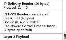
Each L2TPv3 packet contains an L2TPv3 header that includes a unique session ID representing one session and cookie of variable length. The L2TPv3 Session ID and Cookie field lengths are assigned through CLI. For more information about the CLI commands for L2TPv3, see the How to Configure Layer 2 Tunneling Protocol Version 3 section.
The L2TPv3 header comprises the following:
Session ID
The L2TPv3 session ID identifies the session context on the decapsulating system. For dynamic sessions, the value of the session ID is selected to optimize the context identification efficiency of the decapsulating system. A decapsulation implementation may, therefore, elect to support a smaller session ID bit field. In this L2TPv3 implementation, an upper value for the L2TPv3 session ID was set at 023. The L2TPv3 session ID value 0 is reserved for use by the protocol. For static sessions, the session ID is manually configured.
 Note |
The local session ID must be unique on the decapsulating system and is restricted to the least significant ten bits. |
Session Cookie
The L2TPv3 header contains a control channel cookie field. The control channel cookie field has a variable length of 0, 4, or 8 bytes according to the cookie length supported by a given platform for packet decapsulation. The control channel cookie length can be configured manually for static sessions or determined dynamically for dynamic sessions.
The variable cookie length does not present a problem when the same platform is at both ends of an L2TPv3 control channel. However, when different platforms interoperate across an L2TPv3 control channel, both platforms need to encapsulate packets with a 4-byte cookie length.
Pseudowire Control Encapsulation
The L2TPv3 pseudowire control encapsulation consists of 32 bits (4 bytes) and contains information used to sequence L2TP packets (see the Sequencing section). For the purposes of sequencing, only the first bit and bits 8 to 31 are relevant. Bit 1 indicates whether the Sequence Number field, bits 8 to 31, contains a valid sequence number and is to be updated.
L2TPv3 Operation
L2TPv3 includes the following features:
- Xconnect for Layer 2 tunneling through a pseudowire over an IP network
- Layer 2 VPNs for PE-to-PE router service using xconnect that supports Ethernet and VLAN, including both static and dynamic (using the new L2TPv3 signaling) forwarded sessions
The initial Cisco IOS software supported only the following features:
- Layer 2 tunneling (as used in an L2TP access concentrator or LAC) to an attachment circuit, not Layer 3 tunneling
- L2TPv3 data encapsulation directly over IP (IP protocol number 115), not using the UDP
- Point-to-point sessions, not point-to-multipoint or multipoint-to-point sessions
- Sessions between the same Layer 2 protocols, such as Ethernet-to-Ethernet and VLAN-to-VLAN, but not VLAN-to-Ethernet
The attachment circuit is the physical interface or subinterface attached to the pseudowire.
The figure below shows how the L2TPv3 feature is used for setting up VPNs using Layer 2 tunneling over an IP network. All traffic between two customer network sites is encapsulated in IP packets carrying L2TP data messages and sent across an IP network. The backbone routers of the IP network treat the traffic as any other IP traffic and need not know anything about the customer networks.
| Figure 2 | L2TPv3 Operation |
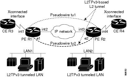
In the figure above, the PE routers R1 and R2 provide L2TPv3 services. The R1 and R2 routers communicate with each other using a pseudowire over the IP backbone network through a path comprising interfaces int1 and int2, the IP network, and interfaces int3 and int4.
In this example, the customer edge (CE) routers R3 and R4 communicate through a pair of xconnect Ethernet or VLAN interfaces using an L2TPv3 session. The L2TPv3 session tu1 is a pseudowire configured between interface int1 on R1 and interface int4 on R2. Any packet arriving on interface int1 on R1 is encapsulated and sent through the pseudowire control channel (tu1) to R2. R2 decapsulates the packet and sends it on interface int4 to R4. When R4 needs to send a packet to R3, the packet follows the same path in reverse.
Note the following features regarding the L2TPv3 operation:
- All packets received on interface int1 are forwarded to R4. R3 and R4 cannot detect the intervening network.
- For Ethernet interfaces, any packet received from LAN1 by R1 on Ethernet interface e1 is encapsulated directly in IP and sent through the pseudowire session tu2 to R2 interface e2, where it is sent on LAN2.
- A VLAN on an Ethernet interface can be mapped to an L2TPv3 session.
L2TPv3 Features
L2TPv3 provides xconnect support for Ethernet and VLAN using Static and Dynamic sessions.
- Static L2TPv3 Sessions
- Dynamic L2TPv3 Sessions
- Control Channel Parameters
- L2TPv3 Control Channel Authentication Parameters
- Ethernet over L2TPv3
- Sequencing
- L2TPv3 Type of Service Marking
- Keepalive
- MTU Handling
- L2TPv3 Control Message Hashing
- L2TPv3 Control Message Rate Limiting
- L2TPv3 Digest Secret Graceful Switchover
- L2TPv3 Pseudowire
- Manual Clearing of L2TPv3 Tunnels
- L2TPv3 Tunnel Management
- L2TPv3 Protocol Demultiplexing
- L2TPv3 Custom Ethertype for Dot1q and QinQ Encapsulations
- HDLC over L2TPv3
Static L2TPv3 Sessions
Typically, the L2TP control plane is responsible for negotiating session parameters, such as the session ID or the cookie, to set up the session. However, some IP networks require sessions to be configured so that no signaling is required for session establishment. You can set up static L2TPv3 sessions for a PE router by configuring fixed values for the fields in the L2TP data header. A static L2TPv3 session allows the PE router to tunnel Layer 2 traffic as soon as the attachment circuit to which the session is bound comes up.
Static configuration allows sessions to be established without dynamically negotiating control connection parameters. This means that although sessions are displayed in the show l2tun session command output, no control channel information is displayed in the show l2tun tunnel command output.
Note |
In an L2TPv3 static session, you can still run the L2TP control channel to perform peer authentication and dead-peer detection. If the L2TP control channel cannot be established or is torn down because of a hello failure, the static session is also torn down. |
If you use a static L2TPv3 session, you cannot perform circuit interworking, such as LMI, because there is no facility to exchange control messages. To perform circuit interworking, you must use a dynamic session.
Dynamic L2TPv3 Sessions
A dynamic L2TP session is established through the exchange of control messages containing attribute-value (AV) pairs. Each AV pair contains information about the nature of the Layer 2 link being forwarded, including the payload type and virtual circuit (VC) ID.
Multiple L2TP sessions, one for each forwarded Layer 2 circuit, can exist between a pair of PE routers and can be maintained by a single control channel. Session IDs and cookies are dynamically generated and exchanged as part of a dynamic session setup. Information such as sequencing configuration is also exchanged. Circuit state changes (UP/DOWN) are conveyed using the set link info (SLI) message.
Control Channel Parameters
The L2TP class configuration procedure creates a template of L2TP control channel parameters that can be inherited by different pseudowire classes. L2TP control channel parameters are used in control channel authentication, keepalive messages, and control channel negotiation. In an L2TPv3 session, the same L2TP class must be specified in the pseudowire configured on the PE router at each end of the control channel. Configuring L2TP control channel parameters is optional. However, the L2TP class must be configured before it is associated with a pseudowire class (see the Configuring the L2TPv3 Pseudowire task).
L2TPv3 Control Channel Authentication Parameters
Two methods of control channel message authentication are available: the L2TPv3 Control Message Hashing feature and CHAP-style L2TP control channel. The L2TPv3 Control Message Hashing feature introduces a more robust authentication method than the older, CHAP-style L2TP control channel method of authentication. You may choose to enable both the methods of authentication to ensure interoperability with peers that support only one of these methods of authentication, but this configuration will yield control of the authentication method used on the peer PE router. Enabling both the methods of authentication should be considered as an interim solution to solve backward compatibility issues during software upgrades.
The principal difference between the two methods of authentication lies in the L2TPv3 Control Message Hashing feature using the entire message in the hash instead of computing the hash over selected contents of a received control message. In addition, instead of including the hash digest in only the start control channel replay (SCCRP) and start control channel connected (SCCCN) messages, it includes it in all messages.
Support for L2TP control channel authentication is maintained for backward compatibility. Either or both authentication methods can be enabled to allow interoperability with peers supporting only one of the authentication methods.
The table below shows a compatibility matrix for the different L2TPv3 authentication methods. PE1 is running the new authentication method. The possible authentication configurations for PE1 are shown in the first column. The other columns represent PE2 running software with different available authentication options. The tables cells in these columns indicate compatible configuration options for PE2. If any PE1/PE2 authentication configuration poses ambiguity about the authentication method used, the winning authentication method is indicated in bold. If both the old and new authentication methods are enabled on PE1 and PE2, both types of authentication occur.
| Table 1 | Compatibility Matrix for L2TPv3 Authentication Methods |
| PE1 Authentication Configuration |
PE2 Supporting Old Authentication1 |
PE2 Supporting New Authentication2 |
PE2 Supporting Old and New Authentication3 |
|---|---|---|---|
| None |
None |
None New integrity check |
None New integrity check |
| Old authentication |
Old authentication |
-- |
Old authentication Old authentication and new authentication Old authentication and new integrity check |
| New authentication |
-- |
New authentication |
New authentication Old authentication and new authentication |
| New integrity check |
None |
None New integrity check |
None New integrity check |
| Old and new authentication |
Old authentication |
New authentication |
Old authentication New authentication Old and new authentication Old authentication and new integrity check |
| Old authentication and new integrity check |
Old authentication |
-- |
Old authentication Old authentication and new authentication Old authentication and new integrity check |
Ethernet over L2TPv3
The Ethernet over L2TPv3 feature provides support for Ethernet-based Layer 2 payload tunneling over IP core networks using L2TPv3.
The Ethernet over L2TPv3 feature supports the following like-to-like switching modes:
- Ethernet port mode
- Ethernet VLAN mode
- Ethernet VLAN mode with VLAN rewrite
- Ethernet QinQ and QinAny mode
Note |
The QinQ over L2TPv3 support feature includes QinAny over L2TPv3, which has a fixed outer VLAN tag and a variable inner VLAN tag. |
The Ethernet over L2TPv3 feature supports the following types of internetworking:
- Ethernet port to VLAN (routed)
- Ethernet port to VLAN (bridged)
- QinQ to Ethernet VLAN or Port Interworking (routed)
- QinQ to Ethernet VLAN or Port Interworking (bridged)
Note |
QinAny Interworking is not a valid configuration because the inner VLAN tag is undetermined. |
Sequencing
Although the correct sequence of received Layer 2 frames is guaranteed by some Layer 2 technologies (by the nature of the link such as a serial line) or by the protocol itself, forwarded Layer 2 frames may be lost, duplicated, or reordered when they traverse a network as IP packets. If the Layer 2 protocol does not provide an explicit sequencing mechanism, you can configure L2TP to sequence its data packets according to the data channel sequencing mechanism described in the L2TPv3 IETF l2tpext working group draft.
A receiver of L2TP data packets mandates sequencing through the Sequencing Required AV pair when the session is being negotiated. A sender (or one that is manually configured to send sequenced packets) that receives this AV pair uses the Layer 2-specific pseudowire control encapsulation defined in L2TPv3.
You can configure L2TP to drop only out-of-order packets; you cannot configure L2TP to deliver the packets out-of-order. No reordering mechanism is available.
Interworking is not allowed when sequencing is enabled.
L2TPv3 Type of Service Marking
When Layer 2 traffic is tunneled across an IP network, information contained in the Type of Service (ToS) bits may be transferred to the L2TP-encapsulated IP packets in one of the following ways:
- If the tunneled Layer 2 frames themselves encapsulate IP packets, it may be desirable to simply copy the ToS bytes of the inner IP packets to the outer IP packet headers. This action is known as "ToS byte reflection."
- You can specify the ToS byte value used by all packets sent across the pseudowire. This is known as "Static ToS byte configuration".
For more details on how to configure ToS, see the Example: Configuring a Negotiated L2TPv3 Session for Local HDLC Switching section.
Keepalive
The keepalive mechanism for L2TPv3 extends only to the endpoints of the tunneling protocol. L2TP has a reliable control message delivery mechanism that serves as the basis for the keepalive mechanism. The keepalive mechanism consists of an exchange of L2TP hello messages.
If a keepalive mechanism is required, the control plane is used, although it may not be used to bring up sessions. You can configure sessions manually.
In the case of static L2TPv3 sessions, a control channel between the two L2TP peers is negotiated through the exchange of start control channel request (SCCRQ), SCCRP, and SCCCN control messages. The control channel is responsible for maintaining only the keepalive mechanism through the exchange of hello messages.
The interval between hello messages is configurable per control channel. If one peer detects that the other peer has gone down through the keepalive mechanism, it sends a StopCCN control message and then notifies all the pseudowires to the peer about the event. This notification results in the teardown of both manually configured and dynamic sessions.
MTU Handling
It is important that you configure a Maximum Transmission Unit (MTU) appropriate for each L2TPv3 tunneled link. The configured MTU size ensures the following:
- The lengths of the tunneled Layer 2 frames fall below the MTU of the destination attachment circuit.
- The tunneled packets are not fragmented, which forces the receiving PE to reassemble them.
L2TPv3 handles the MTU as follows:
- The default behavior is to fragment packets that are larger than the session MTU.
- If you enable the ip dfbit set command in the pseudowire class, the default MTU behavior changes so that any packets that cannot fit within the tunnel MTU are dropped.
- If you enable the ip pmtu command in the pseudowire class, the L2TPv3 control channel participates in the path MTU (PMTU) discovery.
If you enable this feature, the following processing is performed:
- Internet Control Message Protocol (ICMP) unreachable messages sent back to the L2TPv3 router are deciphered and the tunnel MTU is updated accordingly. To receive ICMP unreachable messages for fragmentation errors, the Don't Fragment (DF) bit in the tunnel header is either set according to the DF bit value received from the CE device or set statically if the ip dfbit set option is enabled. The tunnel MTU is periodically reset to the default value based on a periodic timer.
- ICMP unreachable messages are sent back to the clients on the CE side. ICMP unreachable messages are sent to the CE whenever IP packets arrive on the CE-PE interface and have a packet size greater than the tunnel MTU. A Layer 2 header calculation is performed before the ICMP unreachable message is sent to the CE.
L2TPv3 Control Message Hashing
The L2TPv3 Control Message Hashing feature introduces a new and more secure authentication system that replaces the CHAP-like authentication system inherited from L2TPv2, which uses the Challenge and Challenge Response AV pairs in the SCCRQ, SCCRP, and SCCCN messages. The L2TPv3 Control Message Hashing feature incorporates an optional authentication or integrity check for all control messages.
The per-message authentication introduced by the L2TPv3 Control Message Hashing feature is designed to:
- Perform a mutual authentication between L2TP nodes.
- Check integrity of all control messages.
- Guard against control message spoofing and replay attacks that would otherwise be trivial to mount against the network.
The new authentication method uses the following:
- A computed, one-way hash over the header and body of the L2TP control message
- A preconfigured, shared secret that must be defined on the communicating L2TP nodes
- A local and remote random value exchanged using the Nonce AV pairs
Received control messages that lack any of the required security elements are dropped.
L2TPv3 control message integrity checking is a unidirectional mechanism that does not require the configuration of a shared secret. If integrity checking is enabled on the local PE router, control messages are sent with the message digest calculated without the shared secret or Nonce AV pairs and are verified by the remote PE router. If verification fails, the remote PE router drops the control message.
Enabling the L2TPv3 Control Message Hashing feature will impact performance during control channel and session establishment because additional digest calculation of the full message content is required for each sent and received control message. This is an expected trade-off for the additional security provided by this feature. In addition, network congestion may occur if the receive window size is too small. If the L2TPv3 Control Message Hashing feature is enabled, message digest validation must be enabled. Message digest validation deactivates the data path received sequence number update and restricts the minimum local receive window size to 35.
You may choose to configure control channel authentication or control message integrity checking. Control channel authentication requires participation by both peers and a shared secret must be configured on both routers. Control message integrity check is unidirectional and requires configuration on only one of the peers.
L2TPv3 Control Message Rate Limiting
The L2TPv3 Control Message Rate Limiting feature was introduced to counter the possibility of a denial-of-service (DoS) attack on a router running L2TPv3. The L2TPv3 Control Message Rate Limiting feature limits the rate at which SCCRQ control packets arriving at the PE that terminates the L2TPv3 tunnel can be processed. SCCRQ control packets initiate the process of bringing up the L2TPv3 tunnel and require a large amount of control plane resources of the PE router.
No configuration is required for the L2TPv3 Control Message Rate Limiting feature. This feature automatically runs in the background in supported releases.
L2TPv3 Digest Secret Graceful Switchover
Authentication of L2TPv3 control channel messages occurs using a password that is configured on all participating peer PE routers. Before the introduction of this feature, changing this password required removing of the old password from the configuration before adding the new password, causing an interruption in L2TPv3 services. The authentication password must be updated on all peer PE routers, which are often at different physical locations. It is difficult for all peer PE routers to be updated with the new password simultaneously to minimize interruptions in L2TPv3 services.
The L2TPv3 Digest Secret Graceful Switchover feature allows the password used to authenticate L2TPv3 control channel messages to be changed without tearing down the established L2TPv3 tunnels. This feature works only for authentication passwords configured with the L2TPv3 Control Message Hashing feature. Authentication passwords configured with the older, CHAP-like authentication system cannot be updated without tearing down L2TPv3 tunnels.
The L2TPv3 Digest Secret Graceful Switchover feature allows two control channel passwords to be configured simultaneously, so a new control channel password can be enabled without first removing the old password. Established tunnels are rapidly updated with the new password, but continue to use the old password until it is removed from the configuration. This allows authentication to continue normally with peer PE routers that have not yet been updated to use the new password. After all peer PE routers are configured with the new password, the old password can be removed from the configuration.
During the period when both a new and an old password are configured, authentication will occur only with the new password if the attempt to authenticate using the old password fails.
L2TPv3 Pseudowire
The pseudowire class configuration procedure creates a configuration template for the pseudowire. Use this template or class to configure session-level parameters for L2TPv3 sessions that are used to transport attachment circuit traffic over the pseudowire.
The pseudowire configuration specifies the characteristics of the L2TPv3 signaling mechanism, including the data encapsulation type, the control protocol, sequencing, Layer 3 fragmentation, payload-specific options, and IP properties. The setting that determines whether signaling is used to set up the pseudowire is also included.
If you specify the encapsulation l2tpv3 command, you cannot remove it by using the no encapsulation l2tpv3 command. You also cannot change the command setting by using the encapsulation mpls command. These methods result in the following error message:
Encapsulation changes are not allowed on an existing pw-class.
To remove the command, you must delete the pseudowire by using the no pseudowire-class command. To change the type of encapsulation, remove the pseudowire by using the no pseudowire-class command, reestablish the pseudowire, and specify the new encapsulation type.
Manual Clearing of L2TPv3 Tunnels
This feature lets you clear L2TPv3 tunnels manually. Before the introduction of this feature, there was no provision to clear a specific L2TPv3 tunnel manually. This functionality provides users more control over an L2TPv3 network.
L2TPv3 Tunnel Management
New and enhanced commands have been introduced to facilitate the management and diagnosis of problems with xconnect configurations. No specific configuration tasks are associated with these commands.
- debug vpdn--The output of this command includes authentication failure messages.
- show l2tun session--The hostname keyword allows the peer hostname to be displayed in the output.
- show l2tun tunnel--The authentication keyword allows the display of global information about L2TP control channel authentication AV pairs.
- show xconnect--The output of this command displays information about xconnect attachment circuits and pseudowires. This command also provides a sortable, single point of reference for information about all xconnect configurations.
- xconnect logging pseudowire status--This command enables syslog reporting of pseudowire status events.
For information about these Cisco IOS commands, go to the Command Lookup Tool at http://tools.cisco.com/Support/CLILookup or to the Cisco IOS Master Commands List, All Releases.
L2TPv3 Protocol Demultiplexing
The L2TPv3 Protocol Demultiplexing feature introduces the ability to provide native IPv6 support by utilizing a specialized IPv6 network to offload IPv6 traffic from the IPv4 network. The IPv6 traffic is tunneled to the IPv6 network transparently by using L2TPv3 pseudowires without affecting the configuration of the CE routers. IPv4 traffic is routed as usual within the IPv4 network, maintaining the existing performance and reliability of the IPv4 network.
The IPv4 PE routers must be configured to demultiplex the incoming IPv6 traffic from IPv4 traffic. The PE routers facing the IPv6 network do not require the IPv6 configuration. The configuration of the IPv6 network is beyond the scope of this document. For more information on configuring an IPv6 network, see the IPv6 Configuration Guide.
L2TPv3 Custom Ethertype for Dot1q and QinQ Encapsulations
The L2TPv3 Custom Ethertype for Dot1q and QinQ Encapsulations feature lets you configure an Ethertype other than 0x8100 on Gigabit Ethernet interfaces with the QinQ or Dot1Q encapsulation. You can set the custom Ethertype to 0x9100, 0x9200, or 0x88A8. This allows interoperability in a multivendor Gigabit Ethernet environment.
HDLC over L2TPv3
HDLC for Layer 2 Data Encapsulation provides encapsulation of port-to-port Layer 2 traffic. All HDLC traffic including IPv4, IPv6, and non-IP packet, such as IS-IS, is tunneled over L2TPv3. HDLC does not support interworking mode.
Note |
L2TPv3 supports the IPv4 tunnel only for HDLC. The IPv4 tunnel supports IPv4 and IPv6 packets. |
L2TPv3 Benefits
Simplifies Deployment of VPNs
L2TPv3 is an industry-standard Layer 2 tunneling protocol that ensures interoperability among vendors, thus increasing customer flexibility and service availability.
Omits the Need for MPLS
Service providers need not deploy Multiprotocol Label Switching (MPLS) in the core IP backbone to set up VPNs using L2TPv3 over the IP backbone, resulting in operational savings and increased revenue.
Supports Layer 2 Tunneling over IP for Any Payload
L2TPv3 provides enhancements to L2TP to support Layer 2 tunneling of any payload over an IP core network. L2TPv3 defines the base L2TP protocol as being separate from the Layer 2 payload that is tunneled.
Other Benefits
Supported L2TPv3 Payloads
Note |
Each L2TPv3 tunneled packet includes the entire Layer 2 frame of the payloads described in this section. If sequencing is required (see the Sequencing section), a Layer 2-specific sublayer (see the Pseudowire Control Encapsulation section) is included in the L2TPv3 header to provide the Sequence Number field. |
Ethernet
An Ethernet frame arriving at a PE router is simply encapsulated in its entirety with an L2TP data header. At the other end, a received L2TP data packet is stripped of its L2TP data header. The payload, an Ethernet frame, is then forwarded to the appropriate attachment circuit.
Because the L2TPv3 tunneling protocol serves essentially as a bridge, it need not examine any part of an Ethernet frame. Any Ethernet frame received on an interface is tunneled, and any L2TP-tunneled Ethernet frame is forwarded out of the interface.
Note |
Because of the way in which L2TPv3 handles Ethernet frames, an Ethernet interface must be configured to promiscuous mode to capture all traffic received on the Ethernet segment attached to the router. All frames are tunneled through the L2TP pseudowire. |
VLAN
L2TPv3 supports VLAN memberships in the following ways:
- Port-based, in which undated Ethernet frames are received
- VLAN-based, in which tagged Ethernet frames are received
In L2TPv3, Ethernet xconnect supports port-based VLAN membership and the reception of tagged Ethernet frames. A tagged Ethernet frame contains a tag header (defined in 802.1Q), which is 4 bytes long and consists of a 2-byte tag protocol identifier (TPID) field and a 2-byte tag control information (TCI) field. The TPID indicates that a TCI follows. The TCI is further broken down into the following three fields:
For L2TPv3, an Ethernet subinterface configured to support VLAN switching may be bound to an xconnect service so that all Ethernet traffic, tagged with a VID specified on the subinterface, is tunneled to another PE. The VLAN Ethernet frames are forwarded in their entirety. The receiving PE may rewrite the VID of the tunneled traffic to another value before forwarding the traffic onto an attachment circuit.
To successfully rewrite VLANs, it may be necessary to disable the Spanning Tree Protocol (STP). This can be done on a per-VLAN basis by using the no spanning-tree vlan command.
Note |
Because of the way in which L2TPv3 handles VLAN packets, the Ethernet interface must be configured in promiscuous mode to capture all traffic received on the Ethernet segment attached to the router. All frames are tunneled through the L2TP pseudowire. |
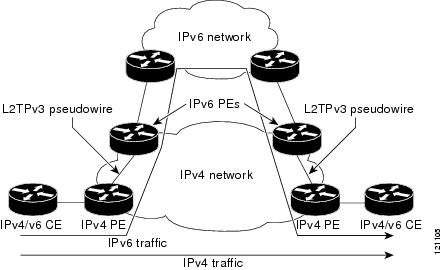
IPv6 Protocol Demultiplexing
Upgrading a service provider network to support IPv6 is a long and expensive process. As an interim solution, the Protocol Demultiplexing for L2TPv3 feature introduces the ability to provide native IPv6 support by setting up a specialized IPv6 network and offloading IPv6 traffic from the IPv4 network. IPv6 traffic is tunneled transparently to the IPv6 network using L2TPv3 pseudowires without affecting the configuration of the CE routers. IPv4 traffic is routed as usual within the IPv4 network, maintaining the existing performance and reliability of the IPv4 network.
The figure below shows a network deployment that offloads IPv6 traffic from the IPv4 network to a specialized IPv6 network. The PE routers demultiplex the IPv6 traffic from the IPv4 traffic. IPv6 traffic is routed to the IPv6 network over an L2TPv3 pseudowire, while IPv4 traffic is routed normally. The IPv4 PE routers must be configured to demultiplex the incoming IPv6 traffic from the IPv4 traffic. The PE routers facing the IPv6 network do not require the IPv6 configuration.
| Figure 3 | Protocol Demultiplexing of IPv6 Traffic from IPv4 Traffic |
If no IP address is configured, the protocol demultiplexing configuration is rejected. If an IP address is configured, the xconnect command configuration is rejected unless protocol demultiplexing is enabled in xconnect configuration mode before exiting that mode. If an IP address is configured with an xconnect command configuration and protocol demultiplexing is enabled, the IP address cannot be removed. To change or remove the configured IP address, the xconnect command configuration must first be disabled.
The table below shows the valid combinations of configurations.
| Table 2 | Valid Configuration Scenarios |
| Scenario |
IP Address |
xconnect Configuration |
Protocol Demultiplexing Configuration |
|---|---|---|---|
| Routing |
Yes |
No |
-- |
| L2VPN |
No |
Yes |
No |
| IPv6 Protocol Demultiplexing |
Yes |
Yes |
Yes |
Supported Shared Port Adapters for Cisco ASR 1000 Series Routers
The following shared port adapters (SPAs) support L2TPv3 on the Cisco ASR 1000 Series Routers:
- SPA-4X1FE-TX-V2 (4-Port 10BASE-T/100BASE-TX Fast Ethernet)
- SPA-8X1FE-TX-V2 (8-Port 10BASE-T/100BASE-TX Fast Ethernet)
- SPA-2X1GE-V2 (2-port Gigabit Ethernet)
- SPA-5X1GE-V2 (5-port Gigabit Ethernet)
- SPA-8X1GE-V2 (8-port Gigabit Ethernet)
- SPA-10XGE-V2 (10-port Gigabit Ethernet)
- SPA-1X10GE-L-V2 (1-port Gigabit Ethernet)
Performance Impact of L2TPv3 on Cisco ASR 1000 Series Routers
L2TPv3 supports the following maximum number of attachment circuits and tunnels:
- First-generation Cisco ASR 1000 Series Route Processor (RP1) with Embedded Services Processor 10 (ESP10)
- Second-generation Cisco ASR 1000 Series Route Processor (RP2) with Embedded Services Processor 20 (ESP20)
L2TPv3 adds tunnel encapsulation to TCP packets, which can cause fragmentation of big packets (packet size larger than the session MTU). Consider a scenario where a big TCP packet is followed by a small TCP packet (packet size smaller than the session MTU). After L2TPv3 encapsulation, the encapsulated big TCP packet will be fragmented, but the encapsulated small TCP packet will not be fragmented. On the Cisco ASR 1000 Series Routers, the fragmentation and reassembly of the big TCP packet requires an additional processor cycle. Because Cisco ASR 1000 Series Routers follow multithread processing, the small packet will need shorter processing time and may be forwarded ahead of the fragmented big packet. This process may result in packet sequence changes on the receiver's end.
As a workaround, you can enable the ip pmtu command to prevent the fragmentation of tunneled packets (see the MTU Handling section).
How to Configure Layer 2 Tunneling Protocol Version 3
- Configuring L2TP Control Channel Parameters
- Configuring the L2TPv3 Pseudowire
- Configuring the Xconnect Attachment Circuit
- Manually Configuring L2TPv3 Session Parameters
- Configuring Protocol Demultiplexing for L2TPv3
- Configuring an L2TPv3 Custom Ethertype for Dot1q and QinQ Encapsulations
- Manually Clearing L2TPv3 Tunnels
Configuring L2TP Control Channel Parameters
After you enter L2TP class configuration mode, you can configure L2TP control channel parameters in any order. If you have multiple authentication requirements, you can configure multiple sets of L2TP class control channel parameters with different L2TP class names. However, only one set of parameters can be applied to a connection between any pair of IP addresses.
- Configuring L2TP Control Channel Timing Parameters
- Configuring L2TPv3 Control Channel Authentication Parameters
- Configuring L2TP Control Channel Maintenance Parameters
Configuring L2TP Control Channel Timing Parameters
The following L2TP control channel timing parameters can be configured in L2TP class configuration mode:
- Packet size of the receive window used for the control channel
- Retransmission parameters used for control messages
- Timeout parameters used for the control channel
This task configures a set of timing control channel parameters in an L2TP class. All of the timing control channel parameter configurations are optional and may be configured in any order. If these parameters are not configured, default values are applied.
DETAILED STEPS
Configuring L2TPv3 Control Channel Authentication Parameters
- Configuring Authentication for the L2TP Control Channel
- Configuring L2TPv3 Control Message Hashing
- Configuring L2TPv3 Digest Secret Graceful Switchover
Configuring Authentication for the L2TP Control Channel
The L2TP control channel method of authentication is the older, CHAP-like authentication system inherited from L2TPv2.
The following L2TP control channel authentication parameters can be configured in L2TP class configuration mode:
- Authentication for the L2TP control channel
- Password used for L2TP control channel authentication
- Local hostname used for authenticating the control channel
This task configures a set of authentication control channel parameters in an L2TP class. All of the authentication control channel parameter configurations are optional and may be configured in any order. If these parameters are not configured, default values are applied.
DETAILED STEPS
Configuring L2TPv3 Control Message Hashing
This task configures L2TPv3 Control Message Hashing feature for an L2TP class.
DETAILED STEPS
| Command or Action | Purpose | |||
|---|---|---|---|---|
|
|
Example: Router> enable |
Enables privileged EXEC mode. |
||
|
|
Example: Router# configure terminal |
Enters global configuration mode. |
||
|
|
Example: Router(config)# l2tp-class class1 |
Specifies the L2TP class name and enters L2TP class configuration mode. |
||
|
|
Example: Router(config-l2tp-class)# digest secret cisco hash sha |
(Optional) Enables L2TPv3 control channel authentication or integrity checking.
The default hash function is md5. |
||
|
|
Example: Router(config-l2tp-class)# digest check |
(Optional) Enables the validation of the message digest in received control messages.
|
||
|
|
Example: Router(config-l2tp-class)# hidden |
(Optional) Enables AV pair hiding when sending control messages to an L2TPv3 peer.
|
||
|
|
Example: Router(config-l2tp-class)# exit |
Exits L2TP class configuration mode. |
Configuring L2TPv3 Digest Secret Graceful Switchover
Perform this task to make the transition from an old L2TPv3 control channel authentication password to a new L2TPv3 control channel authentication password without disrupting established L2TPv3 tunnels.
Before performing this task, you must enable control channel authentication as documented in the Configuring L2TPv3 Control Message Hashing task.
Note |
This task is not compatible with authentication passwords configured with the older, CHAP-like control channel authentication system. |
DETAILED STEPS
| Command or Action | Purpose | |||
|---|---|---|---|---|
|
|
Example: Router> enable |
Enables privileged EXEC mode. |
||
|
|
Example: Router# configure terminal |
Enters global configuration mode. |
||
|
|
Example: Router(config)# l2tp-class class1 |
Specifies the L2TP class name and enters L2TP class configuration mode. |
||
|
|
Example: Router(config-l2tp-class)# digest secret cisco2 hash sha |
Configures a new password to be used in L2TPv3 control channel authentication.
|
||
|
|
Example: Router(config-l2tp-class)# end |
Ends your configuration session by exiting to privileged EXEC mode. |
||
|
|
Example: Router# show l2tun tunnel all |
(Optional) Displays the current state of Layer 2 tunnels and information about configured tunnels, including local and remote L2TP hostnames, aggregate packet counts, and control channel information.
|
||
|
|
Example: Router# configure terminal |
Enters global configuration mode. |
||
|
|
Example: Router(config)# l2tp-class class1 |
Specifies the L2TP class name and enters L2TP class configuration mode. |
||
|
|
Example: Router(config-l2tp-class)# no digest secret cisco hash sha |
Removes the old password used in L2TPv3 control channel authentication.
|
||
|
|
Example: Router(config-l2tp-class)# end |
Ends your configuration session by exiting to privileged EXEC mode. |
||
|
|
Example: Router# show l2tun tunnel all |
(Optional) Displays the current state of Layer 2 tunnels and information about configured tunnels, including local and remote L2TP hostnames, aggregate packet counts, and control channel information.
|
Configuring L2TP Control Channel Maintenance Parameters
The L2TP hello packet keepalive interval control channel maintenance parameter can be configured in L2TP class configuration mode.
This task configures the interval used for hello messages in an L2TP class. This control channel parameter configuration is optional. If this parameter is not configured, the default value is applied.
DETAILED STEPS
Configuring the L2TPv3 Pseudowire
Perform this task to configure the L2TPv3 pseudowire.
DETAILED STEPS
| Command or Action | Purpose | |||||||
|---|---|---|---|---|---|---|---|---|
|
|
Example: Router> enable |
Enables privileged EXEC mode. |
||||||
|
|
Example: Router# configure terminal |
Enters global configuration mode. |
||||||
|
|
Example: Router(config)# pseudowire-class etherpw |
Enters pseudowire class configuration mode and optionally specifies the name of the L2TP pseudowire class. |
||||||
|
|
Example: Router(config-pw)# encapsulation l2tpv3 |
Specifies that L2TPv3 is used as the data encapsulation method to tunnel IP traffic. |
||||||
|
|
Example: Router(config-pw)# protocol l2tpv3 class1 |
(Optional) Specifies the L2TPv3 signaling protocol to be used to manage the pseudowires created with the control channel parameters in the specified L2TP class (see the Configuring L2TP Control Channel Parameters task). |
||||||
|
|
Example: Router(config-pw)# ip local interface e0/0 |
Specifies the PE router interface whose IP address is to be used as the source IP address for sending tunneled packets.
|
||||||
|
|
Example: Router(config-pw)# ip pmtu |
(Optional) Enables the discovery of the PMTU for tunneled traffic and helps fragmentation.
|
||||||
|
|
Example: Router(config-pw)# ip tos reflect |
(Optional) Configures the value of the ToS byte in IP headers of tunneled packets, or reflects the ToS byte value from the inner IP header. |
||||||
|
|
Example: Router(config-pw)# ip dfbit set |
(Optional) Configures the value of the DF bit in the outer headers of tunneled packets. | ||||||
|
|
Example: Router(config-pw)# ip ttl 100 |
(Optional) Configures the value of the time to live (TTL) byte in the IP headers of tunneled packets. |
||||||
|
|
Example: Router(config-pw)# ip protocol l2tp |
(Optional) Configures the IP protocol to be used for tunneling packets. |
||||||
|
|
Example: Router(config-pw)# sequencing both |
(Optional) Specifies the direction in which sequencing of data packets in a pseudowire is enabled:
|
||||||
|
|
Example: Router(config-pw)# exit |
Exits pseudowire class configuration mode. |
Configuring the Xconnect Attachment Circuit
The virtual circuit identifier that you configure creates the binding between a pseudowire configured on a PE router and an attachment circuit in a CE device. The virtual circuit identifier configured on the PE router at one end of the L2TPv3 control channel must also be configured on the peer PE router at the other end.
DETAILED STEPS
| Command or Action | Purpose | |||||
|---|---|---|---|---|---|---|
|
|
Example: Router> enable |
Enables privileged EXEC mode. |
||||
|
|
Example: Router# configure terminal |
Enters global configuration mode. |
||||
|
|
Example: Router(config)# interface ethernet 0/0 |
Specifies the interface by type (for example, Ethernet), slot, and port number, and enters interface configuration mode. |
||||
|
|
Example: Router(config-if)# xconnect 10.0.3.201 123 pw-class vlan-xconnect |
Specifies the IP address of the peer PE router and the 32-bit virtual circuit identifier shared between the PE at each end of the control channel.
|
||||
|
|
Example: Router(config-if)# exit |
Exits interface configuration mode. |
Manually Configuring L2TPv3 Session Parameters
When you bind an attachment circuit to an L2TPv3 pseudowire for the xconnect service by using the xconnect l2tpv3 manual command (see the Configuring the Xconnect Attachment Circuit task) because you do not want signaling, you must configure L2TP-specific parameters to complete the L2TPv3 control channel configuration.
DETAILED STEPS
| Command or Action | Purpose | |||
|---|---|---|---|---|
|
|
Example: Router> enable |
Enables privileged EXEC mode. |
||
|
|
Example: Router# configure terminal |
Enters global configuration mode. |
||
|
|
Example: Router(config)# interface ethernet 0/0 |
Specifies the interface by type (for example, Ethernet), slot, and port number, and enters interface configuration mode. |
||
|
|
Example: Router(config-if)# xconnect 10.0.3.201 123 encapsulation l2tpv3 manual pw-class vlan-xconnect |
Specifies the IP address of the peer PE router and the 32-bit virtual circuit identifier shared between the PE at each end of the control channel, and enters xconnect configuration mode.
|
||
|
|
Example: Router(config-if-xconn)# l2tp id 222 111 |
Configures the identifiers for the local L2TPv3 session and for the remote L2TPv3 session on the peer PE router. |
||
|
|
Example: Router(config-if-xconn)# l2tp cookie local 4 54321 |
(Optional) Specifies the value that the peer PE must include in the cookie field of incoming (received) L2TP packets. |
||
|
|
Example: Router(config-if-xconn)# l2tp cookie remote 4 12345 |
(Optional) Specifies the value that the router includes in the cookie field of outgoing (sent) L2TP packets. |
||
|
|
Example: Router(config-if-xconn)# l2tp hello l2tp-defaults |
(Optional) Specifies the L2TP class name to be used (see the Configuring L2TP Control Channel Parameters task) for control channel configuration parameters, including the interval to use between hello keepalive messages.
|
||
|
|
Example: Router(config-if-xconn)# exit |
Exits xconnect configuration mode. |
||
|
|
Example: Router(config-if)# exit |
Exits interface configuration mode. |
Configuring Protocol Demultiplexing for L2TPv3
Configuring Protocol Demultiplexing for Ethernet Interfaces
Perform this task to configure the Protocol Demultiplexing feature on an Ethernet interface.
DETAILED STEPS
| Command or Action | Purpose | |||
|---|---|---|---|---|
|
|
Example: Router> enable |
Enables privileged EXEC mode. |
||
|
|
Example: Router# configure terminal |
Enters global configuration mode. |
||
|
|
Example: Router(config)# interface ethernet 0/1 |
Specifies the interface by type, slot, and port number, and enters interface configuration mode. |
||
|
|
Example: Router(config-if)# ip address 172.16.128.4 |
Sets a primary or secondary IP address for an interface. |
||
|
|
Example: Router(config-if)# xconnect 10.0.3.201 888 pw-class demux |
Specifies the IP address of the peer PE router and the 32-bit VCI shared between the PE at each end of the control channel, and enters xconnect configuration mode.
|
||
|
|
Example: Router(config-if-xconn)# match protocol ipv6 |
Enables protocol demultiplexing of IPv6 traffic. |
||
|
|
Example: Router(config-if-xconn)# exit |
Exits xconnect configuration mode. |
||
|
|
Example: Router(config-if)# exit |
Exits interface configuration mode. |
Configuring an L2TPv3 Custom Ethertype for Dot1q and QinQ Encapsulations
The L2TPv3 Custom Ethertype for Dot1q and QinQ Encapsulations feature lets you configure an Ethertype other than 0x8100 on Gigabit Ethernet interfaces with QinQ or Dot1Q encapsulations. You can set the custom Ethertype to 0x9100, 0x9200, or 0x88A8. To define the Ethertype field type, you use the dot1q tunneling ethertype command.
Perform this task to set a custom Ethertype.
DETAILED STEPS
Manually Clearing L2TPv3 Tunnels
Perform this task to manually clear a specific L2TPv3 tunnel and all the sessions in that tunnel.
DETAILED STEPS
Configuration Examples for Layer 2 Tunneling Protocol Version 3
Note |
The IP addresses used in this document are not intended to be actual addresses. Any examples, command display output, and figures included in the document are shown for illustrative purposes only. Any use of actual IP addresses in illustrative content is unintentional and coincidental. |
- Example: Configuring a Static L2TPv3 Session for an Xconnect Ethernet Interface
- Example: Configuring a Negotiated L2TPv3 Session for an Xconnect VLAN Subinterface
- Example: Verifying an L2TPv3 Session
- Example: Verifying an L2TP Control Channel
- Example: Configuring L2TPv3 Control Channel Authentication
- Example: Configuring L2TPv3 Digest Secret Graceful Switchover
- Example: Verifying L2TPv3 Digest Secret Graceful Switchover
- Example: Configuring a Pseudowire Class for Fragmentation of IP Packets
- Example: Configuring Protocol Demultiplexing for L2TPv3
- Example: Manually Clearing an L2TPv3 Tunnel
- Example: Configuring an L2TPv3 Custom Ethertype for Dot1q and QinQ Encapsulations
- Example: Configuring an L2TPv3 HDLC Like-to-Like Layer 2 Transport
Example: Configuring a Static L2TPv3 Session for an Xconnect Ethernet Interface
L2TPv3 is the only encapsulation method that supports a manually provisioned session setup. This example shows how to configure a static session configuration in which all control channel parameters are set up in advance. There is no control plane used and no negotiation phase to set up the control channel. The PE router starts sending tunneled traffic as soon as the Ethernet interface (int e0/0) comes up. The virtual circuit identifier, 123, is not used. The PE sends L2TP data packets with session ID 111 and cookie 12345. In turn, the PE expects to receive L2TP data packets with session ID 222 and cookie 54321.
l2tp-class l2tp-defaults
 retransmit initial retries 30
 cookie-size 8
pseudowire-class ether-pw
 encapsulation l2tpv3
 protocol none
 ip local interface Loopback0
interface Ethernet 0/0
 xconnect 10.0.3.201 123 encapsulation l2tpv3 manual pw-class ether-pw
 l2tp id 222 111
 l2tp cookie local 4 54321
 l2tp cookie remote 4 12345
 l2tp hello l2tp-defaults
Example: Configuring a Negotiated L2TPv3 Session for an Xconnect VLAN Subinterface
The following is a sample configuration of a dynamic L2TPv3 session for a VLAN xconnect interface. In this example, only VLAN traffic with a VLAN ID of 5 is tunneled. In the other direction, the L2TPv3 session identified by a virtual circuit identifier of 123 receives forwarded frames whose VLAN ID fields are rewritten to contain the value 5. L2TPv3 is used as both the control plane protocol and the data encapsulation.
l2tp-class class1
 authentication
 password secret
pseudowire-class vlan-xconnect
 encapsulation l2tpv3
 protocol l2tpv3 class1
 ip local interface Loopback0
interface Ethernet0/0.1
 encapsulation dot1Q 5
 xconnect 10.0.3.201 123 pw-class vlan-xconnect
Example: Verifying an L2TPv3 Session
To display information about current L2TPv3 sessions on a router, use the show l2tun session brief command.
Router# show l2tun session brief
L2TP Session Information Total tunnels 1 sessions 1
LocID      TunID      Peer-address    State     Username, Intf/
                                      sess/cir  Vcid, Circuit
2391726297 2382731778 6.6.6.6         est,UP    100, Gi0/2/0
To display detailed information about current L2TPv3 sessions on a router, use the show l2tun session all command.
Router# show l2tun session all
L2TP Session Information Total tunnels 1 sessions 1
Session id 2391726297 is up, logical session id 36272, tunnel id 2382731778
  Remote session id is 193836624, remote tunnel id 2280318174
  Locally initiated session
  Unique ID is 12
Session Layer 2 circuit, type is Ethernet, name is GigabitEthernet0/2/0
  Session vcid is 100
  Circuit state is UP
    Local circuit state is UP
    Remote circuit state is UP
Call serial number is 98300002
Remote tunnel name is l2tp-asr-2
  Internet address is 6.6.6.6
Local tunnel name is l2tp-asr-1
  Internet address is 3.3.3.3
IP protocol 115
  Session is L2TP signaled
  Session state is established, time since change 00:05:25
    94 Packets sent, 58 received
    9690 Bytes sent, 5642 received
  Last clearing of counters never
  Counters, ignoring last clear:
    94 Packets sent, 58 received
    9690 Bytes sent, 5642 received
    Receive packets dropped:
      out-of-order:             0
      other:                    0
      total:                    0
Send packets dropped:
      exceeded session MTU:     0
      other:                    0
      total:                    0
  DF bit off, ToS reflect disabled, ToS value 0, TTL value 255
  Sending UDP checksums are disabled
  Received UDP checksums are verified
  No session cookie information available
  FS cached header information:
    encap size = 24 bytes
    45000014 00000000 ff73a965 03030303
    06060606 0b8db650
  Sequencing is off
  Conditional debugging is disabled
  SSM switch id is 4101, SSM segment id is 12294
Example: Verifying an L2TP Control Channel
The L2TP control channel is used to negotiate capabilities, monitor the health of the peer PE router, and set up various components of an L2TPv3 session.
To display information about L2TP control channels to other L2TP-enabled devices for all L2TP sessions on the router, use the show l2tun tunnel command.Router# show l2tun tunnel
L2TP Tunnel Information Total tunnels 1 sessions 1
LocTunID RemTunID Remote Name State Remote Address Sessn L2TP Class/
Count VPDN Group
2382731778 2280318174 l2tp-asr-2 est 6.6.6.6 1 l2tp_default_cl To display detailed information about L2TP control channels to other L2TP-enabled devices for all L2TP sessions on the router, use the
show l2tun tunnel all command.
Router# show l2tun tunnel all
L2TP Tunnel Information Total tunnels 1 sessions 1
Tunnel id 2382731778 is up, remote id is 2280318174, 1 active sessions
  Locally initiated tunnel
  Tunnel state is established, time since change 00:02:59
  Tunnel transport is IP  (115)
  Remote tunnel name is l2tp-asr-2
    Internet Address 6.6.6.6, port 0
  Local tunnel name is l2tp-asr-1
    Internet Address 3.3.3.3, port 0
  L2TP class for tunnel is l2tp_default_class
  Counters, taking last clear into account:
    54 packets sent, 35 received
    5676 bytes sent, 3442 received
  Last clearing of counters never
  Counters, ignoring last clear:
    54 packets sent, 35 received
    5676 bytes sent, 3442 received
Control Ns 5, Nr 4
  Local RWS 1024 (default), Remote RWS 1024
  Control channel Congestion Control is disabled
  Tunnel PMTU checking disabled
  Retransmission time 1, max 1 seconds
  Unsent queuesize 0, max 0
  Resend queuesize 0, max 2
  Total resends 0, ZLB ACKs sent 2
  Total out-of-order dropped pkts 0
  Total out-of-order reorder pkts 0
  Total peer authentication failures 0
  Current no session pak queue check 0 of 5
  Retransmit time distribution: 0 0 0 0 0 0 0 0 0
  Control message authentication is disabled
Example: Configuring L2TPv3 Control Channel Authentication
l2tp-class class0
 authentication
 password cisco
The following example shows how to configure control channel authentication using the L2TPv3 Control Message Hashing feature:
l2tp-class class1
 digest secret cisco hash sha
 hidden
The following example shows how to configure control channel integrity checking and how to disable validation of the message digest using the L2TPv3 Control Message Hashing feature:
l2tp-class class2
 digest hash sha
 no digest check
The following example shows how to disable the validation of the message digest using the L2TPv3 Control Message Hashing feature:
l2tp-class class3
 no digest check
Example: Configuring L2TPv3 Digest Secret Graceful Switchover
The following example shows how to use the L2TPv3 Digest Secret Graceful Switchover feature to change the L2TP control channel authentication password for the L2TP class named class1. This example assumes that you already have an old password configured for the L2TP class named class1.
Router(config)# l2tp-class class1
Router(config-l2tp-class)# digest secret cisco2 hash sha
!
! Verify that all peer PE routers have been updated to use the new password before
! removing the old password.
!
Router(config-l2tp-class)# no digest secret cisco hash sha
Example: Verifying L2TPv3 Digest Secret Graceful Switchover
The following show l2tun tunnel all command output shows information about the L2TPv3 Digest Secret Graceful Switchover feature:
Router# show l2tun tunnel all
! The output below displays control channel password information for a tunnel which has
! been updated with the new control channel authentication password.
!
Tunnel id 12345 is up, remote id is 54321, 1 active sessions
Control message authentication is on, 2 secrets configured
Last message authenticated with first digest secret
!
! The output below displays control channel password information for a tunnel which has
! only a single control channel authentication password configured.
!
Tunnel id 23456 is up, remote id is 65432, 1 active sessions
!
Control message authentication is on, 1 secrets configured
Last message authenticated with first digest secret
!
! The output below displays control channel password information for a tunnel which is
! communicating with a peer that has only the new control channel authentication password ! configured.
!
Tunnel id 56789 is up, remote id is 98765, 1 active sessions
!
Control message authentication is on, 2 secrets configured
Last message authenticated with second digest secret
Example: Configuring a Pseudowire Class for Fragmentation of IP Packets
The following is a sample configuration of a pseudowire class that will allow IP traffic generated from the CE router to be fragmented before entering the pseudowire:
pseudowire class class1
 encapsulation l2tpv3
 ip local interface Loopback0
 ip pmtu
 ip dfbit set
Example: Configuring Protocol Demultiplexing for L2TPv3
The following example shows how to configure the L2TPv3 Protocol Demultiplexing feature on IPv4 PE routers. The PE routers facing the IPv6 network do not require the IPv6 configuration.
interface ethernet 0/1
 ip address 172.16.128.4
 xconnect 10.0.3.201 888 pw-class demux
  match protocol ipv6
Example: Manually Clearing an L2TPv3 Tunnel
The following example demonstrates how to manually clear a specific L2TPv3 tunnel using the tunnel ID:
clear l2tun tunnel 65432
Example: Configuring an L2TPv3 Custom Ethertype for Dot1q and QinQ Encapsulations
The following example shows how to configure an Ethertype other than 0x8100 on Gigabit Ethernet interfaces with QinQ or Dot1Q encapsulations. In this example, the Ethertype field is set to 0x9100 on Gigabit Ethernet interface 1/0/0.
Router> enable
Router# configure terminal
Router(config)# interface gigabitethernet 1/0/0
Router(config-if)# dot1q tunneling ethertype 0x9100
Example: Configuring an L2TPv3 HDLC Like-to-Like Layer 2 Transport
- Example: Configuring an L2TPv3 HDLC Like-to-Like Layer 2 Transport on Dynamic Mode
- Example: Configuring an L2TPv3 HDLC Like-to-Like Layer 2 Transport on Static Mode
Example: Configuring an L2TPv3 HDLC Like-to-Like Layer 2 Transport on Dynamic Mode
The following example shows how to configure xconnect on a serial interface with HDLC encapsulation on a dynamic mode. The dynamic mode uses L2TPv3 signaling in control channel to set up the L2TPv3 tunnel.
pseudowire-class 774
 encapsulation l2tpv3
 protocol l2tpv3
 ip local interface GigabitEthernet0/0/1.774
!
interface Serial0/2/0:0
 no ip address
 xconnect 4.4.4.4 200 pw-class 774
Example: Configuring an L2TPv3 HDLC Like-to-Like Layer 2 Transport on Static Mode
The following example shows how to configure xconnect on a serial interface with HDLC encapsulation on a static mode. The static mode is used to disable signaling in the L2TPv3 control channel. Since signaling is disabled, you must specify the manual option in xconnect and configure L2TP-specific parameters to complete the L2TPv3 control channel configuration.
pseudowire-class pe1-ether-pw
 encapsulation l2tpv3
 protocol none
 ip local interface Loopback1
!
interface Serial0/2/0:0
 no ip address
 xconnect 2.2.2.2 50 encapsulation l2tpv3 manual pw-class pe1-ether-pw
  l2tp id 111 111
  l2tp cookie local 4 54321
  l2tp cookie remote 4 12345
Additional References
Related Documents
| Related Topic |
Document Title |
|---|---|
| Cisco IOS commands |
|
| Wide area networking commands: complete command syntax, command mode, defaults, usage guidelines and examples |
|
| Configuring Basic Cisco Express Forwarding |
IP Switching Cisco Express Forwarding Configuration Guide, Cisco IOS XE Release 3S |
| IPv6 commands: complete command syntax, command mode, defaults, usage guidelines and examples |
|
| IPv6 configuration tasks |
|
| L2TP |
|
| L2TPv3 |
|
| L2VPN interworking |
"L2VPN Interworking" chapter in the Multiprotocol Label Switching Configuration Guide |
| L2VPN pseudowire switching |
"L2VPN Pseudowire Switching" chapter in the Multiprotocol Label Switching Configuration Guide |
| MTU discovery and packet fragmentation |
|
| VPN commands: complete command syntax, command mode, defaults, usage guidelines and examples |
Standards and RFCs
| Standard/RFC |
Title |
|---|---|
| draft-ietf-l2tpext-l2tp-base-03.txt |
Layer Two Tunneling Protocol (Version 3) "L2TPv3" |
| RFC 1321 |
The MD5 Message Digest Algorithm |
| RFC 2104 |
HMAC-Keyed Hashing for Message Authentication |
| RFC 2661 |
Layer Two Tunneling Protocol "L2TP" |
| RFC 3931 |
Layer Two Tunneling Protocol Version 3 "L2TPv3" |
Technical Assistance
| Description |
Link |
|---|---|
| The Cisco Support and Documentation website provides online resources to download documentation, software, and tools. Use these resources to install and configure the software and to troubleshoot and resolve technical issues with Cisco products and technologies. Access to most tools on the Cisco Support and Documentation website requires a Cisco.com user ID and password. |
Feature Information for Layer 2 Tunneling Protocol Version 3
The following table provides release information about the feature or features described in this module. This table lists only the software release that introduced support for a given feature in a given software release train. Unless noted otherwise, subsequent releases of that software release train also support that feature.
Use Cisco Feature Navigator to find information about platform support and Cisco software image support. To access Cisco Feature Navigator, go to www.cisco.com/go/cfn. An account on Cisco.com is not required.
| Table 3 | Feature Information for Layer 2 Tunneling Protocol Version 3 |
Glossary
AV pairs-- Attribute-value pairs.
CEF--Cisco Express Forwarding. The Layer 3 IP switching technology that optimizes network performance and scalability for networks with large and dynamic traffic patterns.
data-link control layer--Layer 2 in the SNA architectural model. Responsible for the transmission of data over a particular physical link. Corresponds approximately to the data link layer of the OSI model.
DCE--Data circuit-terminating equipment (ITU-T expansion). Devices and connections of a communications network that comprise the network end of the user-to-network interface.
DF bit--Don't Fragment bit. The bit in the IP header that can be set to indicate that the packet should not be fragmented.
DTE--Data terminal equipment. The device at the user end of a user-network interface that serves as a data source, destination, or both.
HDLC--High-Level Data Link Control. A generic link-level communications protocol developed by the ISO. HDLC manages synchronous, code-transparent, serial information transfer over a link connection.
ICMP--Internet Control Message Protocol. A network protocol that handles network errors and error messages.
IDB-- Interface descriptor block.
IS-IS--Intermediate System-to-Intermediate System. The OSI link-state hierarchical routing protocol based on DECnet Phase V routing, whereby ISs (routers) exchange routing information based on a single metric to determine network topology.
L2TP--An extension to PPP that merges features of two tunneling protocols: Layer 2 Forwarding (L2F) from Cisco Systems and Point-to-Point Tunneling Protocol (PPTP) from Microsoft. L2TP is an IETF standard endorsed by Cisco Systems and other networking industry leaders.
L2TPv3--The draft version of L2TP that enhances functionality in RFC 2661 (L2TP).
LMI--Local Management Interface.
MPLS--Multiprotocol Label Switching. A switching method that forwards IP traffic using a label. This label instructs the routers and switches in the network where to forward packets based on preestablished IP routing information.
MQC--Modular quality of service CLI.
MTU--Maximum Transmission Unit. The maximum packet size, in bytes, that a particular interface can handle.
PMTU--Path MTU.
PVC--Permanent virtual circuit. A virtual circuit that is permanently established. A Frame Relay logical link, whose endpoints and class of service are defined by network management. Analogous to an X.25 permanent virtual circuit, a PVC consists of the originating Frame Relay network element address, originating data-link control identifier, terminating Frame Relay network element address, and termination data-link control identifier. Originating refers to the access interface from which the PVC is initiated. Terminating refers to the access interface at which the PVC stops. Many data network customers require a PVC between two points. PVCs save the bandwidth associated with circuit establishment and tear down in situations where certain virtual circuits must exist all the time. Data terminating equipment with a need for continuous communication uses PVCs.
PW--Pseudowire.
SNMP--Simple Network Management Protocol. The network management protocol used almost exclusively in TCP/IP networks. SNMP provides a means to monitor and control network devices and manage configurations, statistics collection, performance, and security.
tunneling--Architecture that is designed to provide the services necessary to implement any standard point-to-point encapsulation scheme.
UNI--User-Network Interface.
VPDN--Virtual private dialup network. A network that allows separate and autonomous protocol domains to share common access infrastructure, including modems, access servers, and ISDN routers. A VPDN enables users to configure secure networks that take advantage of ISPs that tunnel remote access traffic through the ISP cloud.
Cisco and the Cisco Logo are trademarks of Cisco Systems, Inc. and/or its affiliates in the U.S. and other countries. A listing of Cisco's trademarks can be found at www.cisco.com/go/trademarks. Third party trademarks mentioned are the property of their respective owners. The use of the word partner does not imply a partnership relationship between Cisco and any other company. (1005R)
Any Internet Protocol (IP) addresses and phone numbers used in this document are not intended to be actual addresses and phone numbers. Any examples, command display output, network topology diagrams, and other figures included in the document are shown for illustrative purposes only. Any use of actual IP addresses or phone numbers in illustrative content is unintentional and coincidental.
 Feedback