- Finding Feature Information
- Restrictions for Snort IPS
- Information About Snort IPS
- How to Deploy Snort IPS
- Configuration Examples for Snort IPS
- Example: Configuring VirtualPortGroup Interfaces and Virtual Service
- Example: Configuring a Different Resource Profile
- Example: Configuring UTD with Operation Mode IPS and Policy Security
- Example: Configuring Snort IPS Globally
- Example: Configuring Snort IPS Inspection per Interface
- Example: Configuring UTD with VRF on both Inbound and Outbound Interface
- Example: Configuring Logging IOS Syslog
- Example: Configuring Logging to Centralized Log Server
- Example: Configuring Signature Update from a Cisco Server
- Example: Configuring Signature Update from a Local Server
- Example: Configuring Automatic Signature Update
- Example: Performing Manual Signature Update
- Example: Configuring Signature Whitelist
- Examples for Displaying Active Signatures
- Verifying the Integrated Snort IPS Configuration
- Deploying Snort IPS Using Cisco Prime CLI Templates
- Troubleshooting Snort IPS
- Additional References for Snort IPS
- Feature Information for Snort IPS
Snort IPS
The Snort IPS feature enables Intrusion Prevention System (IPS) or Intrusion Detection System (IDS) for branch offices on Cisco 4000 Series Integrated Services Routers and Cisco Cloud Services Router 1000v Series. This feature uses the open source Snort solution to enable IPS and IDS. The Snort IPS feature is available in Cisco IOS XE Release 3.16.1S, 3.17S, and later releases.
 Note | The Virtual Routing and Forwarding (VRF) feature is supported on Snort IPS configuration from Cisco IOS XE Denali Release 16.3.1 and later releases. |
This module explains the feature and how it works.
- Finding Feature Information
- Restrictions for Snort IPS
- Information About Snort IPS
- How to Deploy Snort IPS
- Configuration Examples for Snort IPS
- Examples for Displaying Active Signatures
- Verifying the Integrated Snort IPS Configuration
- Deploying Snort IPS Using Cisco Prime CLI Templates
- Troubleshooting Snort IPS
- Additional References for Snort IPS
- Feature Information for Snort IPS
Finding Feature Information
Your software release may not support all the features documented in this module. For the latest caveats and feature information, see Bug Search Tool and the release notes for your platform and software release. To find information about the features documented in this module, and to see a list of the releases in which each feature is supported, see the feature information table.
Use Cisco Feature Navigator to find information about platform support and Cisco software image support. To access Cisco Feature Navigator, go to www.cisco.com/go/cfn. An account on Cisco.com is not required.
Restrictions for Snort IPS
The following restrictions apply to the Snort IPS feature:
- Incompatible with the Zone-Based Firewall SYN-cookie feature.
- Network Address Translation 64 (NAT64) is not supported.
- IOS syslog is rate limited and as a result, all alerts generated by Snort may not be visible via the IOS Syslog. However, you can view all Syslog messages if you export them to an external log server.
Information About Snort IPS
Snort IPS Overview
The Snort IPS feature enables Intrusion Prevention System (IPS) or Intrusion Detection System (IDS) for branch offices on Cisco 4000 Series Integrated Services Routers and Cisco Cloud Services Router 1000v Series. This feature uses the Snort sensor to provide IPS and IDS functionalities.
Snort is an open source network IPS that performs real-time traffic analysis and generates alerts when threats are detected on IP networks. It can also perform protocol analysis, content searching or matching, and detect a variety of attacks and probes, such as buffer overflows, stealth port scans, and so on. The Snort sensor runs as a virtual container service on Cisco 4000 Series Integrated Services Routers and Cisco Cloud Services Router 1000v Series.
Based on your requirements, you can enable Snort either in IPS or IDS mode. In IDS mode, Snort inspects the traffic and reports alerts, but does not take any action to prevent attacks. In IPS mode, in addition to intrusion detection, actions are taken to prevent attacks.
The Snort IPS monitors the traffic and reports events to an external log server or the IOS syslog. Enabling logging to the IOS syslog may impact performance due to the potential volume of log messages. External third-party monitoring tools, which supports Snort logs, can be used for log collection and analysis.
Snort IPS Signature Package
The community signature package rule set offers limited coverage against threats. The subscriber-based signature package rule set offers the best protection against threats. It includes coverage in advance of exploits, and also provides the fastest access to the updated signatures in response to a security incident or the proactive discovery of a new threat. This subscription is fully supported by Cisco and the package will be updated on Cisco.com. You can download the subscriber-based signature package from the Download Software page.
If the user downloads the signature package manually from the download software page, then the user should ensure that the package has the same version as the Snort engine version. For example, if the Snort engine version is 2982, then the user should download the same version of the signature package. If there is a version mismatch, the signature package update will be rejected and it will fail.
Note | When the signature package is updated, the engine will be restarted and the traffic will be interrupted or bypass inspection for a short period depending on their data plane fail-open/fail-close configuration. |
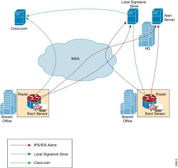
Snort IPS Solution
The Snort IPS solution consists of the following entities:
- Snort sensor—Monitors the traffic to detect anomalies based on the configured security policies (that includes signatures, statistics, protocol analysis, and so on) and sends alert messages to the Alert/Reporting server. The Snort sensor is deployed as a virtual container service on the router.
- Signature store—Hosts the
Cisco Signature packages that are updated periodically. These signature
packages are downloaded to Snort sensors either periodically or on demand.
Validated Signature packages are posted to Cisco.com. Based on the
configuration, signature packages can be downloaded from Cisco.com or a local
server.
Signature packages must be manually downloaded from Cisco.com to the local server by using Cisco.com credentials before the Snort sensor can retrieve them.
The Snort container will perform a domain-name lookup to resolve the location for automatic signature updates from Cisco.com or the local server, if the URL is not specified as the IP address.
- Alert/Reporting server—Receives alert events from the Snort sensor. Alert events generated by the Snort sensor can either be sent to the IOS syslog or an external syslog server or to both IOS syslog and external syslog server. No external log servers are bundled with the Snort IPS solution.
- Management—Manages the Snort IPS solution. Management is configured using the IOS CLI. Snort Sensor cannot be accessed directly, and all configuration can only be done using the IOS CLI.
Overview of Snort Virtual Service Interfaces
The Snort sensor runs as a service on routers. Service containers use virtualization technology to provide a hosting environment on Cisco devices for applications.
You can enable Snort traffic inspection either on a per interface basis or globally on all supported interfaces. The traffic to be inspected is diverted to the Snort sensor and injected back. In Intrusion Detection System (IDS), identified threats are reported as log events and allowed. However, in Intrusion Prevention System (IPS), action is taken to prevent attacks along with log events.
The Snort sensor requires two VirtualPortGroup interfaces. The first VirtualPortGroup interface is used for management traffic and the second for data traffic between the forwarding plane and the Snort virtual container service. Guest IP addresses must be configured for these VirtualPortGroup interfaces. The IP subnet assigned to the management VirtualPortGroup interface should be able to communicate with the Signature server and Alert/Reporting server.
The IP subnet of the second VirtualPortGroup interface must not be routable on the customer network because the traffic on this interface is internal to the router. Exposing the internal subnet to the outside world is a security risk. We recommend the use of 192.0.2.0/30 IP address range for the second VirtualPortGroup subnet. The use of 192.0.2.0/24 subnet is defined in RFC 3330.
You can also use the management interface under the virtual-service command for management traffic. If you configure the management interface, you still need two VirtualPortGroup interfaces. However, do not configure the guest ip address for the first VirtualPortGroup interface.
You can assign the Snort virtual container service IP address on the same management network as the router on which the virtual service is running. This configuration helps if the syslog or update server is on the management network and is not accessible by any other interfaces.
Virtual Service Resource Profile
|
Platform |
Profile |
Virtual Service Resource Requirements |
Platform Requirements |
|
|---|---|---|---|---|
|
System CPU |
Memory |
|||
|
Cisco 4321 ISR |
Default |
50% |
Min: 1GB (RAM) Min: 750MB (Disk/Flash) |
Min: 8GB (RAM) Min: 8GB(Disk/Flash) |
|
Cisco 4331 ISR |
Low (Default) |
25% |
Min: 1GB (RAM) Min: 750MB (Disk/Flash) |
Min: 8GB (RAM) Min: 8GB(Disk/Flash) |
|
Medium |
50% |
Min: 2GB (RAM) Min: 1GB (Disk/Flash) |
Min: 8GB (RAM) Min: 8GB(Disk/Flash) |
|
|
High |
75% |
Min: 4GB (RAM) Min: 2GB (Disk/Flash) |
Min: 8GB (RAM) Min: 8GB(Disk/Flash) |
|
|
Cisco 4351 ISR |
Low (Default) |
25% |
Min: 1GB (RAM) Min: 750MB (Disk/Flash) |
Min: 8GB (RAM) Min: 8GB(Disk/Flash) |
|
Medium |
50% |
Min: 2GB (RAM) Min: 1GB (Disk/Flash) |
Min: 8GB (RAM) Min: 8GB(Disk/Flash) |
|
|
High |
75% |
Min: 4GB (RAM) Min: 2GB (Disk/Flash) |
Min: 8GB (RAM) Min: 8GB(Disk/Flash) |
|
|
Cisco 4431 ISR |
Low (Default) |
25% |
Min: 1GB (RAM) Min: 750MB (Disk/Flash) |
Min: 8GB (RAM) Min: 8GB(Disk/Flash) |
|
Medium |
50% |
Min: 2GB (RAM) Min: 1GB (Disk/Flash) |
Min: 8GB (RAM) Min: 8GB(Disk/Flash) |
|
|
High |
75% |
Min: 4GB (RAM) Min: 2GB (Disk/Flash) |
Min: 12GB (RAM) Min: 12GB(Disk/Flash) |
|
|
Cisco 4451 ISR |
Low (Default) |
25% |
Min: 1GB (RAM) Min: 750MB (Disk/Flash) |
Min: 8GB (RAM) Min: 8GB(Disk/Flash) |
|
Medium |
50% |
Min: 2GB (RAM) Min: 1GB (Disk/Flash) |
Min: 8GB (RAM) Min: 8GB(Disk/Flash) |
|
|
High |
75% |
Min: 4GB (RAM) Min: 2GB (Disk/Flash) |
Min: 12GB (RAM) Min: 12GB(Disk/Flash) |
|
|
Cisco CSR 1000V
|
Low (Default) |
25% |
Min: 1GB (RAM) Min: 750MB (Disk/Flash) |
Min: 8GB (RAM) Min: 8GB(Disk/Flash) |
|
Medium |
50% |
Min: 2GB (RAM) Min: 1GB (Disk/Flash) |
Min: 8GB (RAM) Min: 8GB(Disk/Flash) |
|
|
High |
75% |
Min: 3GB (RAM) Min: 2GB (Disk/Flash) |
Min: 12GB (RAM) Min: 12GB(Disk/Flash) |
|
Deploying Snort IPS
- The Snort OVA file is copied to Cisco routers, installed, and then activated.
- Signature packages are downloaded either from Cisco.com or a configured local server to Cisco routers.
- Network intrusion detection or prevention functionality is configured.
- The Alert/Reporting server is configured to receive alerts from the Snort sensor.
How to Deploy Snort IPS
To deploy Snort IPS on supported devices, perform the following tasks:
- Provision the device.
Identify the device to install the Snort IPS feature.
- Obtain the license.
The Snort IPS functionality is available only in Security Packages which require a security license to enable the service. This feature is available in Cisco IOS XE Release 3.16.1S, 3.17S, and later releases.
Note
Contact Cisco Support to obtain the license. - Install the Snort OVA file.
- Configure VirtualPortGroup interfaces and virtual-service.
- Activate the Snort virtual container service.
- Configure Snort IPS or IDS mode and policy.
- Configure the reporting of events to an external alert/log server or IOS syslog or both.
- Configure the Signature update method.
- Update the Signatures.
- Enable IPS globally or on desired interfaces.
- Installing the Snort OVA File
- Configuring VirtualPortGroup Interfaces and Virtual Service
- Configuring Snort IPS Globally
- Configuring Snort IDS Inspection Globally
- Displaying the List of Active Signatures
Installing the Snort OVA File
An OVA file is an Open Virtualization Archive that contains a compressed, installable version of a virtual machine. The Snort IPS is available as a virtual container service. You must download this OVA file on to the router and use the virtual-service install CLI to install the service.
The service OVA file is not bundled with the Cisco IOS XE Release images that are installed on the router. However, the OVA files may be preinstalled in the flash of the router.
You must use a Cisco IOS XE image with security license. During the OVA file installation, the security license is checked and an error is reported if the license is not present.
1.
enable
2.
virtual-service
install
name
virtual-service-name
package
file-url
media
file-system
3.
show
virtual-service
list
DETAILED STEPS
Configuring VirtualPortGroup Interfaces and Virtual Service
You must configure two VirtualPortGroup interfaces and configure guest IP addresses for both interfaces. However, if you configure a management interface by using the vnic management GigabitEthernet0 command, then do not configure the guest IP address for the first VirtualPortGroup interface.
Note | The VirtualPortGroup interface for data traffic must use a private or nonroutable IP address. We recommend the use of 192.0.2.0/30 IP address range for this interface. |
1.
enable
2.
configure
terminal
3.
interface
VirtualPortGroup
number
4.
ip
address
ip-address
mask
5.
exit
6.
interface
type
number
7.
ip
address
ip-address
mask
8.
exit
9.
virtual-service
name
10.
profile
profile-name
11.
vnic
gateway
VirtualPortGroup
interface-number
12.
guest
ip
address
ip-address
13.
exit
14.
vnic
gateway
VirtualPortGroup
interface-number
15.
guest
ip
address
ip-address
16.
exit
17.
vnic
management
GigabitEthernet0
18.
guest
ip
address
ip-address
19.
exit
20.
activate
21.
end
DETAILED STEPS
| Command or Action | Purpose | |
|---|---|---|
| Step 1 |
enable
Example: Device> enable |
|
| Step 2 |
configure
terminal
Example: Device# configure terminal |
Enters global configuration mode. |
| Step 3 |
interface
VirtualPortGroup
number
Example: Device(config)# interface VirtualPortGroup 0 |
|
| Step 4 |
ip
address
ip-address
mask
Example: Device(config-if)# ip address 10.1.1.1 255.255.255.252 |
Sets a primary IP address for an interface. This interface needs to be routable to the signature update server and external log server. |
| Step 5 |
exit
Example: Device(config-if)# exit |
Exits interface configuration mode and returns to global configuration mode. |
| Step 6 |
interface
type
number
Example: Device(config)# interface VirtualPortGroup 1 |
|
| Step 7 |
ip
address
ip-address
mask
Example: Device(config-if)# ip address 192.0.2.1 255.255.255.252 |
|
| Step 8 |
exit
Example: Device(config-if)# exit |
Exits interface configuration mode and returns to global configuration mode. |
| Step 9 |
virtual-service
name
Example: Device(config)# virtual-service UTDIPS |
|
| Step 10 | profile
profile-name
Example: Device(config-virt-serv)#profile high |
(Optional) Configures a resource profile. If you do not configure the resource profile, the virtual service is activated with its default resource profile. The options are: low, medium, and high. |
| Step 11 |
vnic
gateway
VirtualPortGroup
interface-number
Example: Device(config-virt-serv)# vnic gateway VirtualPortGroup 0 |
|
| Step 12 |
guest
ip
address
ip-address
Example: Device(config-virt-serv-vnic)# guest ip address 10.1.1.2 |
|
| Step 13 |
exit
Example: Device(config-virt-serv-vnic)# exit |
Exits virtual-service vNIC configuration mode and returns to virtual service configuration mode. |
| Step 14 |
vnic
gateway
VirtualPortGroup
interface-number
Example: Device(config-virt-serv)# vnic gateway VirtualPortGroup 1 |
|
| Step 15 |
guest
ip
address
ip-address
Example: Device(config-virt-serv-vnic)# guest ip address 192.0.2.2 |
Configures a guest vNIC address for the vNIC gateway interface. |
| Step 16 |
exit
Example: Device(config-virt-serv-vnic)# exit |
Exits virtual-service vNIC configuration mode and returns to virtual service configuration mode. |
| Step 17 |
vnic
management
GigabitEthernet0
Example: Device(config-virt-serv)# vnic management GigabitEthernet0 |
|
| Step 18 |
guest
ip
address
ip-address
Example: Device(config-virt-serv-vnic)# guest ip address 209.165.201.1 |
(Optional) Configures a guest vNIC address for the vNIC management interface and it must be in the same subnet as the management interface and GigabitEthernet0 configuration. |
| Step 19 |
exit
Example: Device(config-virt-serv-vnic)# exit |
Exits virtual-service vNIC configuration mode and returns to virtual service configuration mode. |
| Step 20 |
activate
Example: Device(config-virt-serv)# activate |
Activates an application installed in a virtual container service. |
| Step 21 |
end
Example: Device(config-virt-serv)# end |
Exits virtual service configuration mode and returns to privileged EXEC mode. |
Configuring Snort IPS Globally
Note | The term global refers to Snort IPS running on all supported interfaces. |
1.
enable
2.
configure
terminal
3.
utd
threat-inspection whitelist
4.
signature
id
signature-id
[comment
description]
5.
exit
6.
utd
engine
standard
7.
logging
{server
hostname
[syslog] |
syslog}
8.
threat-inspection
9.
threat
{detection
|
protection
}
10.
policy
{balanced
|
connectivity
|
security}
11.
whitelist
12.
signature
update
occur-at
{daily
|
monthly
day-of-month
|
weekly
day-of-week} hour
minute
13.
signature
update
server
{cisco
|
url
url
} [username
username
[password
password]]
14.
logging
level
{alert
|
crit
|
debug
|
emerg
|
err
|
info
|
notice
|
warning}
15.
exit
16.
utd
17.
redirect interface
virtualPortGroup interface-number
18.
all-interfaces
19.
engine
standard
20.
fail close
21.
exit
22.
end
DETAILED STEPS
| Command or Action | Purpose | |
|---|---|---|
| Step 1 |
enable
Example: Device> enable | Enables privileged EXEC mode. |
| Step 2 |
configure
terminal
Example: Device# configure terminal |
Enters global configuration mode. |
| Step 3 |
utd
threat-inspection whitelist
Example: Device(config)# utd threat-inspection whitelist |
(Optional) Enables the UTD whitelist configuration mode. |
| Step 4 |
signature
id
signature-id
[comment
description]
Example: Device(config-utd-whitelist)# signature id 24245 comment traffic from branchoffice1 |
Configures signature IDs to be whitelisted. |
| Step 5 |
exit
Example: Device(config-utd-whitelist)# exit |
Exits UTD whitelist configuration mode and returns to global configuration mode. |
| Step 6 |
utd
engine
standard
Example: Device(config)# utd engine standard |
Configures the unified threat defense (UTD) standard engine and enters UTD standard engine configuration mode. |
| Step 7 |
logging
{server
hostname
[syslog] |
syslog}
Example: Device(config-utd-eng-std)# logging server syslog.yourcompany.com |
Enables the logging of emergency messages to a server. |
| Step 8 | threat-inspection
Example: Device(config-utd-eng-std)# threat-inspection |
Configures threat inspection for the Snort engine. |
| Step 9 |
threat
{detection
|
protection
}
Example: Device(config-utd-eng-std-insp)# threat protection |
|
| Step 10 |
policy
{balanced
|
connectivity
|
security}
Example: Device(config-utd-eng-std-insp)# policy security |
Configures the security policy for the Snort engine. |
| Step 11 |
whitelist
Example: Device(config-utd-eng-std-insp)# whitelist |
(Optional) Enables whitelisting under the UTD engine. |
| Step 12 |
signature
update
occur-at
{daily
|
monthly
day-of-month
|
weekly
day-of-week} hour
minute
Example: Device(config-utd-eng-std-insp)# signature update occur-at daily 0 0 |
Configures the signature update interval parameters. This configuration will trigger the signature update to occur at midnight. |
| Step 13 |
signature
update
server
{cisco
|
url
url
} [username
username
[password
password]]
Example: Device(config-utd-eng-std-insp)# signature update server cisco username abcd password cisco123 |
Configures the signature update server parameters. You must specify the signature update parameters with the server details. If you use Cisco.com for signature updates, you must provide the username and password. If you use local server for signature updates, based on the server settings you can provide the username and password. |
| Step 14 |
logging
level
{alert
|
crit
|
debug
|
emerg
|
err
|
info
|
notice
|
warning}
Example: Device(config-utd-eng-std-insp)# logging level emerg |
Enables the log level. |
| Step 15 |
exit
Example: Device(config-utd-eng-std-insp)# exit |
Exits UTD standard engine configuration mode and returns to global configuration mode. |
| Step 16 |
utd
Example: Device(config)# utd |
Enables unified threat defense (UTD) and enters UTD configuration mode. |
| Step 17 | redirect interface
virtualPortGroup interface-number
Example: Device(config-utd)# redirect interface virtualPortGroup 1 |
(Optional) Redirects to a VirtualPortGroup interface. This is the data traffic interface. If you do not configure this interface, it is auto-detected. |
| Step 18 |
all-interfaces
Example: Device(config-utd)# all-interfaces |
Configures UTD on all Layer 3 interfaces of the device. |
| Step 19 |
engine
standard
Example: Device(config-utd)# engine standard |
Configures the Snort-based unified threat defense (UTD) engine and enters standard engine configuration mode. |
| Step 20 | fail close
Example: Device(config-engine-std)# fail close |
(Optional) Defines the action when there is a UTD engine failure. Default option is fail-open. Fail-close option drops all the IPS/IDS traffic when there is an UTD engine failure. Fail-open option allows all the IPS/IDS traffic when there is an UTD engine failure. |
| Step 21 |
exit
Example: Device(config-eng-std)# exit |
Exits standard engine configuration mode and returns to global configuration mode. |
| Step 22 |
end
Example: Device(config-utd)# end |
Exits UTD configuration mode and returns to global configuration mode. |
Configuring Snort IDS Inspection Globally
Based on your requirements, configure either Intrusion Prevention System (IPS) or Intrusion Detection System (IDS) inspection at a global level or at an interface level. Perform this task to configure IDS on a per-interface basis.
1.
enable
2.
configure
terminal
3.
interface
type
number
4.
utd
enable
5.
exit
6. Repeat Steps 3 to 5, on all interfaces that require inspection.
7.
utd
threat-inspection whitelist
8.
signature
id
signature-id
[comment
description]
9.
exit
10.
utd
engine
standard
11.
logging
{server
hostname
[syslog] |
syslog}
12.
threat-inspection
13.
threat
{detection
|
protection
}
14.
policy
{balanced
|
connectivity
|
security}
15.
whitelist
16.
signature
update
occur-at
{daily
|
monthly
day-of-month
|
weekly
day-of-week}
hour
minute
17.
signature
update
server
{cisco
|
url
url} [username
username
[password
password]]
18.
logging
level
{alert
|
crit
|
debug
|
emerg
|
err
|
info
|
notice
|
warning}
19.
exit
20.
utd
21.
redirect interface
virtualPortGroup interface-number
22.
engine
standard
23.
exit
24.
end
DETAILED STEPS
| Command or Action | Purpose | |
|---|---|---|
| Step 1 |
enable
Example: Device> enable | Enables privileged EXEC mode. |
| Step 2 |
configure
terminal
Example: Device# configure terminal |
Enters global configuration mode. |
| Step 3 |
interface
type
number
Example: Device(config)# interface gigabitethernet 0/0/0 |
Configures an interface and enters interface configuration mode. |
| Step 4 |
utd
enable
Example: Device(config-if)# utd enable |
Enables unified threat defense (UTD). |
| Step 5 |
exit
Example: Device(config-if)# exit |
Exits interface configuration mode and returns to global configuration mode. |
| Step 6 | Repeat Steps 3 to 5, on all interfaces that require inspection. |
– |
| Step 7 |
utd
threat-inspection whitelist
Example: Device(config)# utd threat-inspection whitelist |
(Optional) Enables the UTD whitelist configuration mode. |
| Step 8 |
signature
id
signature-id
[comment
description]
Example: Device(config-utd-whitelist)# signature id 24245 comment traffic from branchoffice1 |
Configures signature IDs to be whitelisted. |
| Step 9 |
exit
Example: Device(config-utd-whitelist)# exit |
Exits UTD whitelist configuration mode and returns to global configuration mode. |
| Step 10 |
utd
engine
standard
Example: Device(config)# utd engine standard |
Configures the unified threat defense (UTD) standard engine and enters UTD standard engine configuration mode. |
| Step 11 |
logging
{server
hostname
[syslog] |
syslog}
Example: Device(config-utd-eng-std)# logging syslog |
Enables the logging of critical messages to the IOSd syslog. |
| Step 12 | threat-inspection
Example: Device(config-utd-eng-std)# threat-inspection |
Configures threat inspection for the Snort engine. |
| Step 13 |
threat
{detection
|
protection
}
Example: Device(config-utd-eng-std-insp)# threat detection |
|
| Step 14 |
policy
{balanced
|
connectivity
|
security}
Example: Device(config-utd-eng-std-insp)# policy balanced |
Configures the security policy for the Snort sensor. |
| Step 15 |
whitelist
Example: Device(config-utd-eng-std-insp)# whitelist |
(Optional) Enables whitelisting of traffic. |
| Step 16 |
signature
update
occur-at
{daily
|
monthly
day-of-month
|
weekly
day-of-week}
hour
minute
Example: Device(config-utd-eng-std-insp)# signature update occur-at daily 0 0 |
Configures the signature update interval parameters. This configuration will trigger the signature update to occur at midnight. |
| Step 17 |
signature
update
server
{cisco
|
url
url} [username
username
[password
password]]
Example: Device(config-utd-eng-std-insp)# signature update server cisco username abcd password cisco123 |
Configures the signature update server parameters. You must specify the signature update parameters with the server details. If you use Cisco.com for signature updates, you must provide the username and password. If you use local server for signature updates, based on the server settings you can provide the username and password. |
| Step 18 |
logging
level
{alert
|
crit
|
debug
|
emerg
|
err
|
info
|
notice
|
warning}
Example: Device(config-utd-eng-std-insp)# logging level crit |
Enables the log level. |
| Step 19 |
exit
Example: Device(config-utd-eng-std-insp)# exit |
Exits UTD standard engine configuration mode and returns to global configuration mode. |
| Step 20 |
utd
Example: Device(config)# utd |
Enables unified threat defense (UTD) and enters UTD configuration mode. |
| Step 21 | redirect interface
virtualPortGroup interface-number
Example: Device(config-utd)# redirect interface virtualPortGroup 1 |
(Optional) Redirects to a VirtualPortGroup interface. This is the data traffic interface. If you do not configure this interface, it is auto-detected. |
| Step 22 |
engine
standard
Example: Device(config-utd)# engine standard |
Configures the Snort-based unified threat defense (UTD) engine and enters standard engine configuration mode. |
| Step 23 |
exit
Example: Device(config-eng-std)# exit |
Exits standard engine configuration mode and returns to global configuration mode. |
| Step 24 |
end
Example: Device(config-utd)# end |
Exits UTD configuration mode and returns to global configuration mode. |
Displaying the List of Active Signatures
Active signatures are the ones that prompt Snort IDS/IPS to take action against threats. If the traffic matches with any of the active signatures, Snort container triggers alert in the IDS mode, and drops the traffic in the IPS mode.
The utd threat-inspection signature active-list write-to bootflash: file name command provides a list of active signatures and a summary of the total number of active signatures, drop signatures, and alert signatures.
Configuration Examples for Snort IPS
Example: Configuring VirtualPortGroup Interfaces and Virtual Service
Device# configure terminal
Device(config)# interface VirtualPortGroup 0
Device(config-if)# ip address 10.1.1.1 255.255.255.252
Device(config-if)# exit
Device(config)# interface VirtualPortGroup 1
Device(config-if)# ip address 192.0.2.1 255.255.255.252
Device(config-if)# exit
Device(config)# virtual-service UTDIPS
Device(config-virt-serv)# vnic gateway VirtualPortGroup 0
Device(config-virt-serv-vnic)# exit
Device(config-virt-serv)# vnic gateway VirtualPortGroup 1
Device(config-virt-serv-vnic)# guest ip address 192.0.2.2
Device(config-virt-serv-vnic)# exit
Device(config-virt-serv)# vnic management GigabitEthernet0
Device(config-virt-serv-vnic)# guest ip address 209.165.201.1
Device(config-virt-serv-vnic)# exit
Device(config-virt-serv)# activate
Device(config-virt-serv-vnic)# end
Example: Configuring a Different Resource Profile
Device# configure terminal
Device(config)# virtual-service UTDIPS
Device(config-virt-serv)# no activate
*Sep 7 13:57:04.660 IST: %VIRT_SERVICE-5-ACTIVATION_STATE: Successfully
deactivated virtual service UTDIPS
Device(config-virt-serv)# profile medium
Device(config-virt-serv)# activate
Device(config-virt-serv)# end
Example: Configuring UTD with Operation Mode IPS and Policy Security
The following example shows how to configure the UTD with operation mode IPS and policy security:
Device# configure terminal
Device(config)# utd engine standard
Device(config-utd-eng-std)# threat-inspection
Device(config-utd-eng-std-insp)# threat protection
Device(config-utd-eng-std-insp)# policy security
Device(config-utd-eng-std)# end
Device#
Example: Configuring Snort IPS Globally
The following example shows how to configure Intrusion Prevention System (IPS) globally on a device:
Device# configure terminal
Device(config)# utd engine standard
Device(config-utd-eng-std)# threat-inspection
Device(config-utd-eng-std-insp)# threat protection
Device(config-utd-eng-std-insp)# policy security
Device(config-utd-eng-std)# exit
Device(config)# utd
Device(config-utd)# all-interfaces
Device(config-utd)# engine standard
Device(config-utd-whitelist)# end
Device#
Example: Configuring Snort IPS Inspection per Interface
The following example shows how to configure Snort Intrusion Detection System (IDS) on a per-interface basis:
Device# configure terminal
Device(config)# utd engine standard
Device(config-utd-eng-std)# threat-inspection
Device(config-utd-eng-std-insp)# threat detection
Device(config-utd-eng-std-insp)# policy security
Device(config-utd-eng-std)# exit
Device(config)# utd
Device(config-utd)# engine standard
Device(config-eng-std)# exit
Device(config)# interface gigabitethernet 0/0/0
Device(config-if)# utd enable
Device(config-if)# exit
Example: Configuring UTD with VRF on both Inbound and Outbound Interface
Device# configure terminal
Device(config)# vrf definition VRF1
Device(config-vrf)# rd 100:1
Device(config-vrf)# route-target export 100:1
Device(config-vrf)# route-target import 100:1
Device(config-vrf)# route-target import 100:2
!
Device(config-vrf)# address-family ipv4
Device(config-vrf-af)# exit
!
Device(config-vrf)# address-family ipv6
Device(config-vrf-af)# exit
!
Device(config-vrf-af)# vrf definition VRF2
Device(config-vrf)# rd 100:2
Device(config-vrf)# route-target export 100:2
Device(config-vrf)# route-target import 100:2
Device(config-vrf)# route-target import 100:1
!
Device(config-vrf)# address-family ipv4
Device(config-vrf-af)# exit
!
Device(config-vrf)# address-family ipv6
Device(config-vrf-af)# exit
!
Device(config-vrf)# interface VirtualPortGroup0
Device(config-if)# ip address 192.0.0.1 255.255.255.0
Device(config-if)# no mop enabled
Device(config-if)# no mop sysid
!
Device(config-if)# interface VirtualPortGroup1
Device(config-if)# ip address 192.0.0.1 255.255.255.0
Device(config-if)# no mop enabled
Device(config-if)# no mop sysid
!
Device(config-if)# interface GigabitEthernet0/0/2
Device(config-if)# vrf forwarding VRF1
Device(config-if-vrf)# ip address 192.1.1.5 255.255.255.0
Device(config-if-vrf)# ipv6 address A000::1/64
!
Device(config-if)# interface GigabitEthernet0/0/3
Device(config-if)# vrf forwarding VRF2
Device(config-if-vrf)# ip address 192.1.1.5 255.255.255.0
Device(config-if-vrf)# ipv6 address B000::1/64
!
Device(config-if-vrf)# router bgp 100
Device(config-if-vrf)# bgp log-neighbor-changes
!
Device(config-vrf)# address-family ipv4 vrf VRF1
Device(config-vrf-af)# redistribute connected
Device(config-vrf-af)# redistribute static
Device(config-vrf-af)# exit
!
Device(config-vrf)# address-family ipv6 vrf VRF1
Device(config-vrf-af)# redistribute connected
Device(config-vrf-af)# redistribute static
Device(config-vrf-af)# exit
!
Device(config-vrf)# address-family ipv4 vrf VRF2
Device(config-vrf-af)# redistribute connected
Device(config-vrf-af)# redistribute static
Device(config-vrf-af)# exit
!
Device(config-vrf)# address-family ipv6 vrf VRF2
Device(config-vrf-af)# redistribute connected
Device(config-vrf-af)# redistribute static
Device(config-vrf-af)# exit
!
Device(config)# utd
Device(config-utd)# all-interfaces
Device(config-utd)# engine standard
!
Device(config)# utd engine standard
Device(config-utd-eng-std)# logging syslog
Device(config-utd-eng-std)# threat-inspection
Device(config-utd-engstd-insp)# threat protection
Device(config-utd-engstd-insp)# policy security

!
Device(config)# virtual-service utd
Device(config-virt-serv)# profile low
Device(config-virt-serv)# vnic gateway VirtualPortGroup0
Device(config-virt-serv-vnic)# guest ip address 47.0.0.2
Device(config-virt-serv-vnic)# exit
Device(config-virt-serv)# vnic gateway VirtualPortGroup1
Device(config-virt-serv-vnic)# guest ip address 48.0.0.2
Device(config-virt-serv-vnic)# exit
Device(config-virt-serv)# activate

UTD Snort IPS Drop Log
============================
2016/06/13-14:32:09.524475 IST [**] [Instance_ID: 1] [**] Drop [**]
[1:30561:1] BLACKLIST DNS request for known malware
domain domai.ddns2.biz - Win.Trojan.Beebone [**]
[Classification: A Network Trojan was Detected]
[Priority: 1] [VRF_ID: 2] {UDP} 11.1.1.10:58016 -> 21.1.1.10:53
Example: Configuring Logging IOS Syslog
The following example shows how to configure logging IOS syslog with the log levels on a device:
Device# configure terminal
Device(config)# utd engine standard
Device(config-utd-eng-std)# logging syslog
Device(config-utd-eng-std)# threat-inspection
Device(config-utd-engstd-insp)# logging level debug
Device(config-utd-eng-std-insp)# end
Device#
Example: Configuring Logging to Centralized Log Server
The following example shows how to configure logging to a centralized log server:
Device# configure terminal
Device(config)# utd engine standard
Device(config-utd-eng-std-insp)# logging server syslog.yourcompany.com
Device(config-utd-eng-std)# threat-inspection
Device(config-utd-eng-std-insp)# logging level info
Device(config-utd-eng-std-insp)# end
Device#
Example: Configuring Signature Update from a Cisco Server
The following example shows how to configure the signature update from a Cisco server :
Device# configure terminal
Device(config)# utd engine standard
Device(config-utd-eng-std)# threat-inspection
Device(config-utd-eng-std-insp)# signature update server cisco username CCOuser password passwd123
Device(config-utd-eng-std-insp)# end
Device#
Note | Ensure that the DNS is configured to download signatures from the Cisco server. |
Example: Configuring Signature Update from a Local Server
The following example shows how to configure the signature update from a local server:
Device# configure terminal
Device(config)# utd engine standard
Device(config-utd-eng-std)# threat-inspection
Device(config-utd-eng-std-insp)# signature update server url http://192.168.1.2/sig-1.pkg
Device(config-utd-eng-std-insp)# end
Device#
Example: Configuring Automatic Signature Update
The following example shows how to configure the automatic signature update on a server:
Device# configure terminal
Device(config)# utd engine standard
Device(config-utd-eng-std)# threat-inspection
Device(config-utd-eng-std-insp)# signature update occur-at daily 0 0
Device(config-utd-eng-std-insp)# signature update server cisco username abcd password cisco123
Device(config-utd-eng-std-insp)# end
Device#
Note | When the signature update is not in detail, you can get the signature update from the server. |
Example: Performing Manual Signature Update
The following example shows how to perform a manual signature update:
Device# utd threat-inspection signature update

It takes the existing server configuration to download from
or the explicit server information configured with it.

These commands perform a manual signature update with the below settings:

Device#show utd engine standard threat-inspection signature update status
Current Signature package version: 2982.2.s
Current Signature package name: UTD-STD-SIGNATURE-2982-2-S.pkg
Previous Signature package version: 29.0.c
Last update status: Successful
Last failure Reason: None
Last successful update method: Auto
Last successful update server: cisco
Last successful update time: Fri Jul 1 05:15:43 2016 PDT
Last successful update speed: 2656201 bytes in 42 secs
Last failed update method: Manual
Last failed update server: cisco
Last failed update time: Fri Jul 1 16:51:23 2016 IST
Last attempted update method: Auto
Last attempted update server: cisco
Last attempted update time: Fri Jul 1 05:15:43 2016 PDT
Total num of updates successful: 1
Num of attempts successful: 1
Num of attempts failed: 5
Total num of attempts: 6
Next update scheduled at: None
Current Status: Idle

Device# utd threat-inspection signature update server cisco username ccouser password passwd123
Device# utd threat-inspection signature update server url http://192.168.1.2/sig-1.pkg
Example: Configuring Signature Whitelist
The following example shows how to configure signature whitelist:
Device# configure terminal
Device(config)# utd threat-inspection whitelist
Device(config-utd-whitelist)# signature id 23456 comment "traffic from client x"
Device(config-utd-whitelist)# exit
Device(config)# utd engine standard
Device(config-utd-eng-std)# whitelist
Device(config-utd-eng-std)# end
Device#
Note | After the whitelist signature ID is configured, Snort will allow the flow to pass through the device without any alerts and drops. |
Examples for Displaying Active Signatures
- Example: Displaying Active Signatures List With Balanced Policy
- Example: Displaying Active Signatures List With Security Policy
- Example: Displaying Active Signatures List With Connectivity Policy
Example: Displaying Active Signatures List With Balanced Policy
Device# utd threat-inspection signature active-list write-to bootflash:siglist_balanced
Device# more bootflash:siglist_balanced
=================================================================================
Signature Package Version: 2982.1.s
Signature Ruleset: Balanced
Total no. of active signatures: 7884
Total no. of drop signatures: 7389
Total no. of alert signatures: 495

For more details of each signature please go to www.snort.org/rule_docs to lookup
=================================================================================

List of Active Signatures:
--------------------------
<snipped>
Example: Displaying Active Signatures List With Security Policy
Device# utd threat-inspection signature active-list write-to bootflash:siglist_security
Device# more bootflash:siglist_security
=================================================================================
Signature Package Version: 2982.1.s
Signature Ruleset: Security
Total no. of active signatures: 11224
Total no. of drop signatures: 10220
Total no. of alert signatures: 1004

For more details of each signature please go to www.snort.org/rule_docs to lookup
=================================================================================

List of Active Signatures:
--------------------------
<snipped>
Example: Displaying Active Signatures List With Connectivity Policy
Device# utd threat-inspection signature active-list write-to bootflash:siglist_connectivity
Device# more bootflash:siglist_connectivity
=================================================================================
Signature Package Version: 2982.1.s
Signature Ruleset: Connectivity
Total no. of active signatures: 581
Total no. of drop signatures: 452
Total no. of alert signatures: 129

For more details of each signature please go to www.snort.org/rule_docs to lookup
=================================================================================
List of Active Signatures:
--------------------------
<snipped>
Verifying the Integrated Snort IPS Configuration
Use the following commands to troubleshoot your configuration.
1.
enable
2.
show
virtual-service
list
3.
show
virtual-service
detail
4.
show
service-insertion
type
utd
service-node-group
5.
show
service-insertion
type
utd
service-context
6.
show
utd
engine
standard
config
7.
show
utd
engine
standard
status
8.
show
utd
engine
standard
threat-inspection
signature update
status
9.
show
utd
engine
standard
logging
events
10.
clear
utd
engine
standard
logging
events
11.
show
platform
hardware
qfp
active
feature
utd
config
12.
show
platform
software
utd
global
13.
show
platform
software
utd
interfaces
14.
show
platform
hardware
qfp
active
feature
utd
stats
15.
show
utd
engine
standard
statistics
daq
all
DETAILED STEPS
| Step 1 |
enable
Example: Device> enableEnables privileged EXEC mode. |
| Step 2 |
show
virtual-service
list
Displays the status of the installation of all applications on the virtual service container. Example: Device# show virtual-service list Virtual Service List: Name Status Package Name ------------------------------------------------------------------------------ UTDIPS Activated utdsnort.1_0_1_SV2982_XE_16_3.20160701_131509.ova |
| Step 3 |
show
virtual-service
detail
Displays the resources used by applications installed in the virtual services container of a device. Example: Device# show virtual-service detail
Device#show virtual-service detail
Virtual service UTDIPS detail
State : Activated
Owner : IOSd
Package information
Name : utdsnort.1_0_1_SV2982_XE_16_3.20160701_131509.ova
Path : bootflash:/utdsnort.1_0_1_SV2982_XE_16_3.20160701_131509.ova
Application
Name : UTD-Snort-Feature
Installed version : 1.0.1_SV2982_XE_16_3
Description : Unified Threat Defense
Signing
Key type : Cisco development key
Method : SHA-1
Licensing
Name : Not Available
Version : Not Available
Detailed guest status
----------------------------------------------------------------------
Process Status Uptime # of restarts
----------------------------------------------------------------------
climgr UP 0Y 0W 0D 0: 0:35 1
logger UP 0Y 0W 0D 0: 0: 4 0
snort_1 UP 0Y 0W 0D 0: 0: 4 0
Network stats:
eth0: RX packets:43, TX packets:6
eth1: RX packets:8, TX packets:6
Coredump file(s): lost+found
Activated profile name: None
Resource reservation
Disk : 736 MB
Memory : 1024 MB
CPU : 25% system CPU
Attached devices
Type Name Alias
---------------------------------------------
NIC ieobc_1 ieobc
NIC dp_1_0 net2
NIC dp_1_1 net3
NIC mgmt_1 mgmt
Disk _rootfs
Disk /opt/var
Disk /opt/var/c
Serial/shell serial0
Serial/aux serial1
Serial/Syslog serial2
Serial/Trace serial3
Watchdog watchdog-2
Network interfaces
MAC address Attached to interface
------------------------------------------------------
54:0E:00:0B:0C:02 ieobc_1
A4:4C:11:9E:13:8D VirtualPortGroup0
A4:4C:11:9E:13:8C VirtualPortGroup1
A4:4C:11:9E:13:8B mgmt_1
Guest interface
---
Interface: eth2
ip address: 48.0.0.2/24
Interface: eth1
ip address: 47.0.0.2/24
---
Guest routes
---
Address/Mask Next Hop Intf.
-------------------------------------------------------------------------------
0.0.0.0/0 48.0.0.1 eth2
0.0.0.0/0 47.0.0.1 eth1
---
Resource admission (without profile) : passed
Disk space : 710MB
Memory : 1024MB
CPU : 25% system CPU
VCPUs : Not specified
|
| Step 4 |
show
service-insertion
type
utd
service-node-group
Displays the status of service node groups. Example: Device# show service-insertion type utd service-node-group Service Node Group name : utd_sng_1 Service Context : utd/1 Member Service Node count : 1 Service Node (SN) : 30.30.30.2 Auto discovered : No SN belongs to SNG : utd_sng_1 Current status of SN : Alive Time current status was reached : Tue Jul 26 11:57:48 2016 Cluster protocol VPATH version : 1 Cluster protocol incarnation number : 1 Cluster protocol last sent sequence number : 1469514497 Cluster protocol last received sequence number: 1464 Cluster protocol last received ack number : 1469514496 |
| Step 5 |
show
service-insertion
type
utd
service-context
Displays the AppNav and service node views. Example: Device# show service-insertion type utd service-context Service Context : utd/1 Cluster protocol VPATH version : 1 Time service context was enabled : Tue Jul 26 11:57:47 2016 Current FSM state : Operational Time FSM entered current state : Tue Jul 26 11:57:58 2016 Last FSM state : Converging Time FSM entered last state : Tue Jul 26 11:57:47 2016 Cluster operational state : Operational Stable AppNav controller View: 30.30.30.1 Stable SN View: 30.30.30.2 Current AppNav Controller View: 30.30.30.1 Current SN View: 30.30.30.2 |
| Step 6 |
show
utd
engine
standard
config
Displays the unified threat defense (UTD) configuration. Example: Device# show utd engine standard config UTD Engine Standard Configuration: Operation Mode : Intrusion Prevention Policy : Security Signature Update: Server : cisco User Name : ccouser Password : YEX^SH\fhdOeEGaOBIQAIcOVLgaVGf Occurs-at : weekly ; Days:0 ; Hour: 23; Minute: 50 Logging: Server : IOS Syslog; 10.104.49.223 Level : debug Whitelist Signature IDs: 28878 |
| Step 7 |
show
utd
engine
standard
status
Displays the status of the utd engine. Example: Device# show utd engine standard status Engine version : 1.0.1_SV2982_XE_16_3 Profile : High System memory : Usage : 8.00 % Status : Green Number of engines : 4 Engine Running CFT flows Health Reason ======================================================= Engine(#1): Yes 0 Green None Engine(#2): Yes 0 Green None Engine(#3): Yes 0 Green None Engine(#4): Yes 0 Green None ======================================================= Overall system status: Green Signature update status: ========================= Current Signature package version: 29.0.c Current Signature package name: default Previous Signature package version: None Last update status: None Last failure Reason: None |
| Step 8 |
show
utd
engine
standard
threat-inspection
signature update
status
Displays the status of the signature update process. Example: Device# show utd engine standard threat-inspection signature update status Current Signature package version: 2982.2.s Current Signature package name: UTD-STD-SIGNATURE-2982-2-S.pkg Previous Signature package version: 29.0.c Last update status: Successful Last failure Reason: None Last successful update method: Auto Last successful update server: cisco Last successful update time: Fri Jul 1 05:15:43 2016 PDT Last successful update speed: 2656201 bytes in 42 secs Last failed update method: Manual Last failed update server: cisco Last failed update time: Fri Jul 1 16:51:23 2016 IST Last attempted update method: Auto Last attempted update server: cisco Last attempted update time: Fri Jul 1 05:15:43 2016 PDT Total num of updates successful: 1 Num of attempts successful: 1 Num of attempts failed: 5 Total num of attempts: 6 Next update scheduled at: None Current Status: Idle |
| Step 9 |
show
utd
engine
standard
logging
events
Displays log events from the Snort sensor. Example: Device# show utd engine standard logging events
2016/06/13-14:32:09.524475 IST [**] [Instance_ID: 1] [**] Drop [**] [1:30561:1]
BLACKLIST DNS request for known malware domain domai.ddns2.biz -
Win.Trojan.Beebone [**] [Classification: A Network Trojan was Detected] [Priority: 1]
[VRF_ID: 2] {UDP} 11.1.1.10:58016 -> 21.1.1.10:53
2016/06/13-14:32:21.524988 IST [**] [Instance_ID: 1] [**] Drop [**] [1:30561:1]
BLACKLIST DNS request for known malware domain domai.ddns2.biz -
Win.Trojan.Beebone [**] [Classification: A Network Trojan was Detected] [Priority: 1]
[VRF_ID: 2] {UDP} a000:0:0:0:0:0:0:10:59964 -> b000:0:0:0:0:0:0:10:53
|
| Step 10 |
clear
utd
engine
standard
logging
events
Example: Device# clear utd engine standard logging events Clears logged events from the Snort sensor. |
| Step 11 |
show
platform
hardware
qfp
active
feature
utd
config
Displays information about the health of the service node. Example: Device# show platform hardware qfp active feature utd config Global configuration NAT64: disabled SN threads: 12 CFT inst_id 0 feat id 1 fo id 1 chunk id 8 Context Id: 0, Name: Base Security Ctx Ctx Flags: (0x60000) Engine: Standard SN Redirect Mode : Fail-open, Divert Threat-inspection: Enabled, Mode: IDS Domain Filtering : Not Enabled URL Filtering : Not Enabled SN Health: Green |
| Step 12 |
show
platform
software
utd
global
Displays the interfaces on which UTD is enabled. Example: Device# show platform software utd global UTD Global state Engine : Standard Global Inspection : Enabled Operational Mode : Intrusion Prevention Fail Policy : Fail-open Container techonlogy : LXC Redirect interface : VirtualPortGroup1 UTD interfaces All dataplane interfaces |
| Step 13 |
show
platform
software
utd
interfaces
Displays the information about all interfaces. Example: Device# show platform software utd interfaces UTD interfaces All dataplane interfaces |
| Step 14 |
show
platform
hardware
qfp
active
feature
utd
stats
Displays dataplane UTD statistics. Example: Device# show platform hardware qfp active feature utd stats
Security Context: Id:0 Name: Base Security Ctx
Summary Statistics:
Pkts entered policy feature pkt 228
byt 31083
Drop Statistics:
Service Node flagged flow for dropping 48
Service Node not healthy 62
General Statistics:
Non Diverted Pkts to/from divert interface 32913
Inspection skipped - UTD policy not applicable 48892
Policy already inspected 2226
Pkts Skipped - L2 adjacency glean 1
Pkts Skipped - For Us 67
Pkts Skipped - New pkt from RP 102
Response Packet Seen 891
Feature memory allocations 891
Feature memory free 891
Feature Object Delete 863
Service Node Statistics:
SN Health: Green
SN down 85
SN health green 47
SN health red 13
Diversion Statistics
redirect 2226
encaps 2226
decaps 2298
reinject 2250
decaps: Could not locate flow 72
Redirect failed, SN unhealthy 62
Service Node requested flow bypass drop 48
|
| Step 15 |
show
utd
engine
standard
statistics
daq
all
Displays serviceplane data acquistion (DAQ) statistics. Example: Device# show utd engine standard statistics daq all IOS-XE DAQ Counters(Engine #1): --------------------------------- Frames received :0 Bytes received :0 RX frames released :0 Packets after vPath decap :0 Bytes after vPath decap :0 Packets before vPath decap :0 Bytes before vPath decap :0 Frames transmitted :0 Bytes transmitted :0 Memory allocation :2 Memory free :0 Merged packet buffer allocation :0 Merged packet buffer free :0 VPL buffer allocation :0 VPL buffer free :0 VPL buffer expand :0 VPL buffer merge :0 VPL buffer split :0 VPL packet incomplete :0 VPL API error :0 CFT API error :0 Internal error :0 External error :0 Memory error :0 Timer error :0 Kernel frames received :0 Kernel frames dropped :0 FO cached via timer :0 Cached fo used :0 Cached fo freed :0 FO not found :0 CFT full packets :0 VPL Stats(Engine #1): ------------------------ |
Deploying Snort IPS Using Cisco Prime CLI Templates
You can use the Cisco Prime CLI templates to provision the Snort IPS deployment. The Cisco Prime CLI templates make provisioning Snort IPS deployment simple. To use the Cisco Prime CLI templates to provision the Snort IPS deployment, perform these steps:
| Step 1 | Download the Prime templates from the Software Download page, corresponding to the IOS XE version running on your system. |
| Step 2 | Unzip the file, if it is a zipped version. |
| Step 3 | From Prime, choose Configuration > Templates > Features and Technologies, select CLI Templates. |
| Step 4 | Click Import. |
| Step 5 | Select the
folder where you want to import the templates to and click
Select
Templates and choose the templates that you just downloaded to import.
|
Troubleshooting Snort IPS
Traffic is not Diverted
Device# show virtual-service list Virtual Service List: Name Status Package Name ------------------------------------------------------------------------------ snort Activated utdsnort.1_0_1_SV2982_XE_16_3.20160701_131509.ova
Device# show platform software utd global UTD Global state Engine : Standard Global Inspection : Disabled Operational Mode : Intrusion Prevention Fail Policy : Fail-open Container techonlogy : LXC Redirect interface : VirtualPortGroup1 UTD interfaces GigabitEthernet0/0/0
Device# show platform hardware qfp active feature utd config Global configuration NAT64: disabled SN threads: 12 CFT inst_id 0 feat id 0 fo id 0 chunk id 4 Context Id: 0, Name: Base Security Ctx Ctx Flags: (0x60000) Engine: Standard SN Redirect Mode : Fail-open, Divert Threat-inspection: Enabled, Mode: IDS Domain Filtering : Not Enabled URL Filtering : Not Enabled SN Health: Green
Device# show virtual-service detail
Virtual service UTDIPS detail
State : Activated
Owner : IOSd
Package information
Name : utdsnort.1_0_1_SV2982_XE_16_3.20160701_131509.ova
Path : bootflash:/utdsnort.1_0_1_SV2982_XE_16_3.20160701_131509.ova
Application
Name : UTD-Snort-Feature
Installed version : 1.0.1_SV2982_XE_16_3
Description : Unified Threat Defense
Signing
Key type : Cisco development key
Method : SHA-1
Licensing
Name : Not Available
Version : Not Available
Detailed guest status
----------------------------------------------------------------------
Process Status Uptime # of restarts
----------------------------------------------------------------------
climgr UP 0Y 0W 0D 0: 0:35 1
logger UP 0Y 0W 0D 0: 0: 4 0
snort_1 UP 0Y 0W 0D 0: 0: 4 0
Network stats:
eth0: RX packets:43, TX packets:6
eth1: RX packets:8, TX packets:6
Coredump file(s): lost+found
Activated profile name: None
Resource reservation
Disk : 736 MB
Memory : 1024 MB
CPU : 25% system CPU
Attached devices
Type Name Alias
---------------------------------------------
NIC ieobc_1 ieobc
NIC dp_1_0 net2
NIC dp_1_1 net3
NIC mgmt_1 mgmt
Disk _rootfs
Disk /opt/var
Disk /opt/var/c
Serial/shell serial0
Serial/aux serial1
Serial/Syslog serial2
Serial/Trace serial3
Watchdog watchdog-2
Network interfaces
MAC address Attached to interface
------------------------------------------------------
54:0E:00:0B:0C:02 ieobc_1
A4:4C:11:9E:13:8D VirtualPortGroup0
A4:4C:11:9E:13:8C VirtualPortGroup1
A4:4C:11:9E:13:8B mgmt_1
Guest interface
---
Interface: eth2
ip address: 48.0.0.2/24
Interface: eth1
ip address: 47.0.0.2/24
---
Guest routes
---
Address/Mask Next Hop Intf.
-------------------------------------------------------------------------------
0.0.0.0/0 48.0.0.1 eth2
0.0.0.0/0 47.0.0.1 eth1
---
Resource admission (without profile) : passed
Disk space : 710MB
Memory : 1024MB
CPU : 25% system CPU
VCPUs : Not specified
Device# show service-insertion type utd service-node-group

Service Node Group name : utd_sng_1
Service Context : utd/1
Member Service Node count : 1


Service Node (SN) : 30.30.30.2
Auto discovered : No
SN belongs to SNG : utd_sng_1
Current status of SN : Alive
Time current status was reached : Tue Jul 26 11:57:48 2016

Cluster protocol VPATH version : 1
Cluster protocol incarnation number : 1
Cluster protocol last sent sequence number : 1469514497
Cluster protocol last received sequence number: 1464
Cluster protocol last received ack number : 1469514496
Device# show service-insertion type utd service-context

Service Context : utd/1
Cluster protocol VPATH version : 1
Time service context was enabled : Tue Jul 26 11:57:47 2016
Current FSM state : Operational
Time FSM entered current state : Tue Jul 26 11:57:58 2016
Last FSM state : Converging
Time FSM entered last state : Tue Jul 26 11:57:47 2016
Cluster operational state : Operational

Stable AppNav controller View:
30.30.30.1

Stable SN View:
30.30.30.2

Current AppNav Controller View:
30.30.30.1

Current SN View:
30.30.30.2
Device# show platform hardware qfp active feature utd stats
Security Context: Id:0 Name: Base Security Ctx
Summary Statistics:
Active Connections 29
TCP Connections Created 712910
UDP Connections Created 80
Pkts entered policy feature pkt 3537977
byt 273232057
Pkts entered divert feature pkt 3229148
byt 249344841
Pkts slow path pkt 712990
byt 45391747
Pkts Diverted pkt 3224752
byt 249103697
Pkts Re-injected pkt 3224746
byt 249103373
….
Signature Update is not Working
Device# show utd engine standard threat-inspection signature update status Current Signature package version: 2982.1.s Current Signature package name: UTD-STD-SIGNATURE-2982-1-S.pkg Previous Signature package version: 2982.2.s Last update status: Successful Last failure Reason: System error-fail to process username & password combination. Last successful update method: Manual Last successful update server: http://10.104.52.159/protected/UTD-STD-SIGNATURE-2982-1-S.pkg Last successful update time: Fri Jul 8 14:21:49 2016 IST Last successful update speed: 2631532 bytes in 6 secs Last failed update method: Auto Last failed update server: cisco Last failed update time: Fri Jul 8 14:13:02 2016 IST Last attempted update method: Manual Last attempted update server: http://10.104.52.159/protected/UTD-STD-SIGNATURE-2982-1-S.pkg Last attempted update time: Fri Jul 8 14:21:49 2016 IST Total num of updates successful: 17 Num of attempts successful: 22 Num of attempts failed: 12 Total num of attempts: 34 Next update scheduled at: None Current Status: Idle
Device# show run | i name-server ip name-server 10.104.49.223
Signature Update from the Local Server is not Working
Logging to IOSd Syslog is not Working
Device# show utd engine standard config UTD Engine Standard Configutation: Operation Mode : Intrusion Prevention Policy : Security Signature Update: Server : cisco User Name : ccouser Password : YEX^SH\fhdOeEGaOBIQAIcOVLgaVGf Occurs-at : weekly ; Days:0 ; Hour: 23; Minute: 50 Logging: Server : IOS Syslog; 10.104.49.223 Level : debug Whitelist Signature IDs: 28878
Device# show utd engine standard logging events

2016/06/13-14:32:09.524475 IST [**] [Instance_ID: 1] [**] Drop [**] [1:30561:1]
BLACKLIST DNS request for known malware domain domai.ddns2.biz -
Win.Trojan.Beebone [**] [Classification: A Network Trojan was Detected] [Priority: 1]
[VRF_ID: 2] {UDP} 11.1.1.10:58016 -> 21.1.1.10:53
2016/06/13-14:32:21.524988 IST [**] [Instance_ID: 1] [**] Drop [**] [1:30561:1]
BLACKLIST DNS request for known malware domain domai.ddns2.biz -
Win.Trojan.Beebone [**] [Classification: A Network Trojan was Detected] [Priority: 1]
[VRF_ID: 2] {UDP} a000:0:0:0:0:0:0:10:59964 -> b000:0:0:0:0:0:0:10:53
Logging to an External Server is not Working
ps -eaf | grep syslog

 root 2073 1 0 Apr12 ? 00:00:02 syslogd -r -m
UTD Conditional Debugging
The Snort IPS feature supports UTD conditional debugging. For details on how to configure conditional debugging, see the following URL:
http://www.cisco.com/c/en/us/td/docs/routers/asr1000/troubleshooting/guide/Tblshooting-xe-3s-asr-1000-book.html#task_AC969BB06B414DCBBDEF7ADD29EF8131Additional References for Snort IPS
Related Documents
| Related Topic | Document Title |
|---|---|
|
IOS commands |
|
|
Security commands |
|
Technical Assistance
| Description | Link |
|---|---|
|
The Cisco Support website provides extensive online resources, including documentation and tools for troubleshooting and resolving technical issues with Cisco products and technologies. To receive security and technical information about your products, you can subscribe to various services, such as the Product Alert Tool (accessed from Field Notices), the Cisco Technical Services Newsletter, and Really Simple Syndication (RSS) Feeds. Access to most tools on the Cisco Support website requires a Cisco.com user ID and password. |
Feature Information for Snort IPS
The following table provides release information about the feature or features described in this module. This table lists only the software release that introduced support for a given feature in a given software release train. Unless noted otherwise, subsequent releases of that software release train also support that feature.
Use Cisco Feature Navigator to find information about platform support and Cisco software image support. To access Cisco Feature Navigator, go to www.cisco.com/go/cfn. An account on Cisco.com is not required.|
Feature Name |
Releases |
Feature Information |
|---|---|---|
|
Snort IPS |
Cisco IOS XE 3.16.1S, 3.17S and later releases |
The Snort IPS feature, enables Intrusion Prevention System (IPS) and Intrusion Detection System (IDS) for branch offices on Cisco IOS XE-based platforms. This feature uses the open source Snort solution to enable IPS and IDS. |
|
VRF support on Snort IPS |
Cisco IOS XE Denali 16.3.1 |
Supports Virtual Fragmentation Reassembly (VFR) on Snort IPS configuration. |
|
Snort IPS support on Cisco Cloud Services Router 1000v Series |
Cisco IOS XE Denali 16.3.1 |
Cisco Cloud Services Router 1000v Series supports Snot IPS. |
|
UTD Snort IPS Enhancements for 16.4 Release |
Cisco IOS XE Everest 16.4.1 |
The UTD Snort IPS enhancements for 16.4 release adds a feature for displaying the list of active signatures. |
 Feedback