Contents
- QoS Classification, Policing, and Marking on a LAC
- Finding Feature Information
- Prerequisites for QoS Classification Policing and Marking on a LAC
- Restrictions for QoS Classification, Policing, and Marking on a LAC
- Information About QoS Classification Policing and Marking on a LAC
- Benefits of the QoS Classification Policing and Marking on a LAC Feature
- QoS Policy Maps and a LAC
- Upstream Traffic from the LAC to the LNS
- Downstream Traffic from the LNS to the LAC
- SSS Sessions on the LAC
- How to Configure QoS Classification Policing and Marking on a LAC
- Enabling the Service Provider to Verify Traffic Statistics
- Configuration Examples for QoS Classification, Policing, and Marking on a LAC
- Example Configuring the Routers
- Example Verifying the SSS Session
- Example Applying the QoS Policy Map
- Example Configuring the LAC
- Example Verifying the QoS Policy Map for Downstream Traffic
- Example Applying the QoS Policy Map to the Session
- Example Verifying the QoS Policy Map for Upstream Traffic
- Additional References
- Feature Information for QoS Classification Policing and Marking on a LAC
QoS Classification, Policing, and Marking on a LAC
The QoS Classification, Policing, and Marking on a LAC feature allows service providers to classify packets based upon the IP type of service (ToS) bits in an embedded IP packet. The classification is used to police the incoming traffic according to the differentiated services code point (DSCP) value. The purpose of classifying the packet by examining its encapsulation is to simplify the implementation and configuration needed for a large number of PPP sessions.
- Finding Feature Information
- Prerequisites for QoS Classification Policing and Marking on a LAC
- Restrictions for QoS Classification, Policing, and Marking on a LAC
- Information About QoS Classification Policing and Marking on a LAC
- How to Configure QoS Classification Policing and Marking on a LAC
- Configuration Examples for QoS Classification, Policing, and Marking on a LAC
- Additional References
- Feature Information for QoS Classification Policing and Marking on a LAC
Finding Feature Information
Your software release may not support all the features documented in this module. For the latest caveats and feature information, see Bug Search Tool and the release notes for your platform and software release. To find information about the features documented in this module, and to see a list of the releases in which each feature is supported, see the feature information table at the end of this module.
Use Cisco Feature Navigator to find information about platform support and Cisco software image support. To access Cisco Feature Navigator, go to www.cisco.com/go/cfn. An account on Cisco.com is not required.
Prerequisites for QoS Classification Policing and Marking on a LAC
Configure the Routers
You must configure the client router, the Layer 2 Tunneling Protocol (L2TP) Access Concentrator (LAC), and the L2TP Network Server (LNS) before applying the QoS policy map as described in the "Configuration Examples for QoS Classification, Policing, and Marking on a LAC" section on page 4.
Verify the State of the Subscriber Service Switch Sessions
You must use the show sss session command to verify that the user sessions are enabled on a LAC.
Configure the Interface
You must configure the virtual-template interface before applying the policy map to the session.
Restrictions for QoS Classification, Policing, and Marking on a LAC
Service-policy on PPP over X.25 (PPPoX) interfaces is not supported.
Class-based queueing and class-based shaping are not supported.
Layer 2 marking is not supported.
The QoS MIB is not supported.
The clear counters command does not clear the counters of the QoS policy map.
Multihop virtual private dialup networks (VPDNs) are not supported.
Information About QoS Classification Policing and Marking on a LAC
- Benefits of the QoS Classification Policing and Marking on a LAC Feature
- QoS Policy Maps and a LAC
- Upstream Traffic from the LAC to the LNS
- Downstream Traffic from the LNS to the LAC
- SSS Sessions on the LAC
Benefits of the QoS Classification Policing and Marking on a LAC Feature
This feature provides policing and marking on a per-session basis for traffic forwarded into L2TP tunnels to the appropriate LNS and for traffic coming from an L2TP tunnel toward a customer edge router.
This feature helps recognize the IP ToS value in the Point-to-Point Protocol over Ethernet (PPPoE) encapsulated traffic in order to classify and police the traffic according to the DSCP value.
QoS Policy Maps and a LAC
QoS policing and marking can be achieved by attaching a QoS policy map to the user interface on a LAC in the input and output directions. By using tunnels, input and output service policies can be attached to interfaces. Policy maps get enforced as the packet enters or leaves the tunnel.
The figure below shows the deployment of QoS on PPPoE sessions originating at the client and terminating at the LNS.
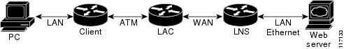
 Note | In this sample topology, the LAC is a Cisco 7200 series router. |
Upstream Traffic from the LAC to the LNS
Upstream traffic corresponds to packets traversing from the tunnel source to the tunnel destination; in this case, the traffic moves from the LAC to the LNS. The input QoS policy map acts on the upstream traffic before the packet gets encapsulated with the tunnel header.
Downstream Traffic from the LNS to the LAC
Downstream traffic corresponds to packets traversing from the tunnel destination to the tunnel source; in this case, the traffic going from the LNS to the LAC. The output QoS policy map acts on the downstream traffic after the tunnel encapsulation is removed from the packet header.
SSS Sessions on the LAC
The Subscriber Service Switch (SSS) session provides you with the infrastructure to apply QoS features on a per-session basis. The SSS session is preconfigured on the virtual template, and you can use this template to provide QoS classification, policing, and marking.
You can verify the statistics of the upstream and downstream traffic from a QoS policy map in an SSS session by using the show policy-map session command.
How to Configure QoS Classification Policing and Marking on a LAC
Enabling the Service Provider to Verify Traffic Statistics
1.
enable
2.
show
policy-map
session
[uid uid-number] [input | output [class class-name]]
3.
exit
DETAILED STEPS
Configuration Examples for QoS Classification, Policing, and Marking on a LAC
The following examples show you how to apply QoS policy maps to upstream and downstream user session traffic to achieve the required Service Level Agreements (SLAs) provided by the service provider.
- Example Configuring the Routers
- Example Verifying the SSS Session
- Example Applying the QoS Policy Map
- Example Configuring the LAC
- Example Verifying the QoS Policy Map for Downstream Traffic
- Example Applying the QoS Policy Map to the Session
- Example Verifying the QoS Policy Map for Upstream Traffic
Example Configuring the Routers
The following example shows the configuration of the routers before the QoS policy map is verified.
Client Configuration
When you log in to the PC, a PPPoE session is established at the client that faces the LAC. This PPPoE session is forwarded through the L2TP tunnel from the LAC to the LNS at which point the PPPoE session terminates.
To apply QoS sessions to the user traffic that originates from the PC to the web server and to the traffic that originates from the web server to the PC, you should apply a QoS policy map to the user session on the LAC in the input and output directions. The classification will be based on the user traffic that originates at the PC and the web traffic that originates at the web server.
This topology supports bidirectional traffic, meaning that traffic can flow from the PC to the web server and from the web server to the PC.
username xyz@cisco.com password 0 password1
username qos4-72a password 0 password1
username qos4-72b password 0 password1
aaa authentication ppp default local
aaa session-id common
ip cef
vpdn enable
!
vpdn-group 1
 request-dialin
  protocol pppoe
!
interface ATM0/0/0
 no ip address
 no ip redirects
 no ip proxy-arp
 no ip mroute-cache
 load-interval 30
 no atm ilmi-keepalive
!
interface ATM0/0/0.1 point-to-point
 pvc 0/100
  encapsulation aal5snap
  pppoe max-sessions 100
  pppoe-client dial-pool-number 1
 !
 interface Dialer1
  mtu 1492
  ip address negotiated
  encapsulation ppp
  dialer pool 1
  no peer default ip address
  no cdp enable
  ppp authentication chap callin
  ppp chap hostname xyz@cisco.com
  ppp chap password 0 cisco
  ppp ipcp dns request
!
LAC Configuration
The following example shows that the interfaces between the client and the LAC are ATM5/0 interfaces.
username xyz@cisco.com password 0 password1
username qos4-72a password 0 password1
username qos4-72b password 0 password1
aaa new-model
!
!
aaa authentication ppp default local
aaa session-id common
ip cef
vpdn enable
!
vpdn-group 1
 accept-dialin
  protocol pppoe
  virtual-template 1
!
vpdn-group 2
 request-dialin
  protocol l2tp
  domain cisco.com
 initiate-to ip 10.10.101.2
 local name lac
 no l2tp tunnel authentication
 ip tos reflect
!
interface Serial0/0/0
 bandwidth 2015
 ip address 10.10.100.1 255.255.255.0
 no ip redirects
 no ip proxy-arp
 load-interval 30
 no keepalive
 no cdp enable
!
interface ATM0/0/0
 no ip address
 no ip redirects
 no ip proxy-arp
 load-interval 30
 no atm ilmi-keepalive
!
interface ATM0/0/0.1 point-to-point
 pvc 0/100
  encapsulation aal5snap
  pppoe max-sessions 100
  protocol ppp Virtual-Template1
  protocol pppoe
!
!
interface Virtual-Template1
 mtu 1492
 no ip address
 no peer default ip address
 ppp authentication chap
!
LNS Configuration
The following example shows that the interface between the LAC and the LNS is a Serial3/6 interface.
username xyz@cisco.com password 0 password1
username qos4-72b password 0 password1
username qos4-72a password 0 password1
aaa new-model
!
!
aaa authentication ppp default local
aaa session-id common
ip cef
vpdn enable
!
vpdn-group 1
 accept-dialin
  protocol any
  virtual-template 1
 terminate-from hostname lac
 local name lns
 lcp renegotiation always
 no l2tp tunnel authentication
 ip tos reflect
!
interface Serial0/0/0
 bandwidth 2015
 ip address 10.10.100.1 255.255.255.0
 no ip redirects
 no ip proxy-arp
 no ip mroute-cache
 load-interval 30
 no keepalive
 no cdp enable
!
Example Verifying the SSS Session
The following example from the show sss sessioncommand shows that a user session is enabled on the LAC:
Router# show sss session
Current SSS Information: Total sessions 1
Uniq ID Type       State         Service      Identifier           Last Chg
401     PPPoE/PPP  connected     Forwarded    xyz@cisco.com        00:02:06
Example Applying the QoS Policy Map
The following output shows a QoS policy map to be applied to the user session in the output direction, which is the downstream traffic coming into the PC from the web server. The first subclass of traffic within the session is marked with dscp af11, the second subclass is policed, and the third subclass is dropped.
class-map match-any customer1234
 match ip dscp cs1  cs2  cs3  cs4
class-map match-any customer56
 match ip dscp cs5  cs6
class-map match-any customer7
 match ip dscp cs7
policy-map downstream-policy
 class customer1234
  set ip dscp af11
 class customer56
  police cir 20000 bc 10000 pir 40000 be 10000
    conform-action set-dscp-transmit af21
    exceed-action set-dscp-transmit af22
    violate-action set-dscp-transmit af23
 class customer7
   drop
Example Configuring the LAC
The following example from the interface virtual-template command shows a QoS policy map being applied to the user session on the LAC:
Router# configure terminal
Router(config)# interface virtual-template1
Router(config-if)# service-policy output downstream-policy
Router(config-if)# end
Example Verifying the QoS Policy Map for Downstream Traffic
In the following example from the show policy-map session command, the QoS policy map is applied for traffic in the downstream direction.
Note | The session ID, 401, is obtained from the output of the show sss session command shown in the "Example Verifying the SSS Session" section on page 7. |
Router# show policy-map session uid 401 output
SSS session identifier 401 -
  Service-policy output: downstream-policy
    Class-map: customer1234 (match-any)
      4464 packets, 249984 bytes
      5 minute offered rate 17000 bps, drop rate 0 bps
      Match: ip dscp cs1  cs2  cs3  cs4
        4464 packets, 249984 bytes
        5 minute rate 17000 bps
      QoS Set
        dscp af11
          Packets marked 4464
    Class-map: customer56 (match-any)
      2232 packets, 124992 bytes
      5 minute offered rate 8000 bps, drop rate 0 bps
      Match: ip dscp cs5  cs6
        2232 packets, 124992 bytes
        5 minute rate 8000 bps
      police:
          cir 20000 bps, bc 10000 bytes
          pir 40000 bps, be 10000 bytes
        conformed 2232 packets, 124992 bytes; actions:
          set-dscp-transmit af21
        exceeded 0 packets, 0 bytes; actions:
          set-dscp-transmit af22
        violated 0 packets, 0 bytes; actions:
          set-dscp-transmit af23
        conformed 8000 bps, exceed 0 bps, violate 0 bps
    Class-map: customer7 (match-any)
      1116 packets, 62496 bytes
      5 minute offered rate 4000 bps, drop rate 4000 bps
      Match: ip dscp cs7
        1116 packets, 62496 bytes
        5 minute rate 4000 bps
      drop
    Class-map: class-default (match-any)
      1236 packets, 68272 bytes
      5 minute offered rate 4000 bps, drop rate 0 bps
      Match: any
Example Applying the QoS Policy Map to the Session
In the following example, the service provider applies a QoS policy map to the user session in order to limit the amount of bandwidth that the user session is permitted to consume in the upstream direction from the PC to the web server:
Router# configure terminal
Router(config)# policy-map upstream-policy
Router(config-pmap)# class class-default
Router(config-pmap-c)# police cir 8000 bc 1500 be 1500 conform-action transmit exceed-action drop
Router(config-if)# end
This QoS policy map is then applied to the user session as follows:
Router# configure terminal
Router(config)# interface virtual-template1
Router(config-if)# service-policy input upstream-policy
Router(config-if)# end
Example Verifying the QoS Policy Map for Upstream Traffic
In the following example from the show policy-map session command, the QoS policy map is applied for traffic in the upstream direction:
Note | The session ID, 401, is obtained from the output of the show sss session command in the "Example Verifying the SSS Session" section on page 7. |
Router# show policy-map session uid 401 input
 SSS session identifier 401 -
  Service-policy input: upstream-policy
    Class-map: class-default (match-any)
      1920 packets, 111264 bytes
      5 minute offered rate 7000 bps, drop rate 5000 bps
      Match: any
      police:
          cir 8000 bps, bc 1500 bytes
        conformed 488 packets, 29452 bytes; actions:
          transmit
        exceeded 1432 packets, 81812 bytes; actions:
          drop
        conformed 7000 bps, exceed 5000 bps
Additional References
Related Documents
|
Related Topic |
Document Title |
|---|---|
|
QoS commands: complete command syntax, command modes, command history, defaults, usage guidelines, and examples |
Cisco IOS Quality of Service Solutions Command Reference |
|
Information about attaching policy maps to interfaces using the modular quality of service (QoS) command-line interface (CLI) (MQC) |
"Applying QoS Features Using the MQC" module |
Standards
|
Standard |
Title |
|---|---|
|
No new or modified standards are supported, and support for existing standards has not been modified. |
-- |
MIBs
|
MIB |
MIBs Link |
|---|---|
|
No new or modified MIBs are supported, and support for existing MIBs has not been modified. |
To locate and download MIBs for selected platforms, Cisco IOS XE Software releases, and feature sets, use Cisco MIB Locator found at the following URL: |
RFCs
|
RFC |
Title |
|---|---|
|
No new or modified RFCs are supported, and support for existing RFCs has not been modified. |
-- |
Technical Assistance
|
Description |
Link |
|---|---|
|
The Cisco Support and Documentation website provides online resources to download documentation, software, and tools. Use these resources to install and configure the software and to troubleshoot and resolve technical issues with Cisco products and technologies. Access to most tools on the Cisco Support and Documentation website requires a Cisco.com user ID and password. |
Feature Information for QoS Classification Policing and Marking on a LAC
The following table provides release information about the feature or features described in this module. This table lists only the software release that introduced support for a given feature in a given software release train. Unless noted otherwise, subsequent releases of that software release train also support that feature.
Use Cisco Feature Navigator to find information about platform support and Cisco software image support. To access Cisco Feature Navigator, go to . An account on Cisco.com is not required.|
Feature Name |
Releases |
Feature Information |
|---|---|---|
|
QoS: Classification, Policing, and Marking on a LAC |
Cisco IOS XE Release 2.1 |
The QoS: Classification, Policing, and Marking on a LAC feature allows service providers to classify packets based upon the IP type of service (ToS) bits in an embedded IP packet. The classification is used to police the incoming traffic according to the differentiated services code point (DSCP) value. The following command was introduced or modified by this feature: show policy-map session. |