- MPLS VPN Inter-AS with ASBRs Exchanging VPN-IPv4 Addresses
- MPLS VPN Inter-AS with ASBRs Exchanging IPv4 Routes and MPLS Labels
- MPLS VPN Multipath Support for Inter-AS VPNs
- MPLS VPN--Inter-AS Option AB
- MPLS VPN Carrier Supporting Carrier Using LDP and an IGP
- MPLS VPN Carrier Supporting Carrier with BGP
- MPLS VPN Load Balancing Support for Inter-AS and CSC VPNs
- MPLS VPN eBGP Multipath Support for CSC and Inter-AS MPLS VPNs
- MPLS VPN Explicit Null Label Support with BGP IPv4 Label Session
Contents
- MPLS VPN Carrier Supporting Carrier Using LDP and an IGP
- Finding Feature Information
- Prerequisites for MPLS VPN CSC with LDP and IGP
- Restrictions for MPLS VPN CSC with LDP and IGP
- Information About MPLS VPN CSC with LDP and IGP
- MPLS VPN CSC Introduction
- Benefits of Implementing MPLS VPN CSC
- Configuration Options for MPLS VPN CSC with LDP and IGP
- Customer Carrier Is an ISP
- Customer Carrier Is a BGP MPLS VPN Service Provider
- How to Configure MPLS VPN CSC with LDP and IGP
- Configuring the Backbone Carrier Core
- Prerequisites
- Verifying IP Connectivity and LDP Configuration in the CSC Core
- Troubleshooting Tips
- Configuring VRFs for CSC-PE Routers
- Troubleshooting Tips
- Configuring Multiprotocol BGP for VPN Connectivity in the Backbone Carrier
- Troubleshooting Tips
- Configuring the CSC-PE and CSC-CE Routers
- Prerequisites
- Configuring LDP on the CSC-PE and CSC-CE Routers
- Enabling MPLS Encapsulation on the CSC-PE and CSC-CE Routers
- Verifying the Carrier Supporting Carrier Configuration
- Configuration Examples for MPLS VPN CSC with LDP and IGP
- MPLS VPN CSC Network with a Customer Who Is an ISP Example
- CSC-CE1 Configuration
- CSC-PE1 Configuration
- CSC-PE2 Configuration
- CSC-CE2 Configuration
- MPLS VPN CSC Network with a Customer Who Is an MPLS VPN Provider Example
- CE1 Configuration
- PE1 Configuration
- CSC-CE1 Configuration
- CSC-PE1 Configuration
- CSC-PE2 Configuration
- CSC-CE2 Configuration
- PE2 Configuration
- CE2 Configuration
- MPLS VPN CSC Network That Contains Route Reflectors Example
- Backbone Carrier Configuration
- Route Reflector 1 (72K-37-1) Configuration
- Route Reflector 2 (72K-38-1) Configuration
- CSC-PE1 (75K-37-3) Configuration
- CSC-PE2 (75K-38-3) Configuration
- Customer Carrier Site 1 Configuration
- PE1 (72K-36-8) Configuration
- CSC-CE1 (72K-36-9) Configuration
- PE2 (72K-36-7) Configuration
- Route Reflector 3 (36K-38-4) Configuration
- CE1 (36K-36-1) Configuration
- Customer Carrier Site 2 Configuration
- CSC-CE3 (72K-36-6) Configuration
- PE3 (72K-36-4) Configuration
- CSC-CE4 (72K-36-5) Configuration
- Route Reflector 4 (36K-38-5) Configuration
- CE2 (36K-36-2) Configuration
- CE3 (36K-36-3) Configuration
- MPLS VPN CSC Network with a Customer Who Has VPNs at the Network Edge Example
- Backbone Carrier Configuration
- CSC-PE1 (72K-36-9) Configuration
- P1 (75K-37-3) Configuration
- P2 (75K-38-3) Configuration
- CSC-PE2 (72K-36-5) Configuration
- Customer Carrier Site 1 Configuration
- CSC-CE1 (72K-36-8) Configuration
- PE2 (72K-36-7) Configuration
- CE1 (36K-36-1) Configuration
- Customer Carrier Site 2 Configuration
- CSC-CE2 (72K-36-4) Configuration
- PE2 (72K-36-6) Configuration
- CE2 (36K-38-4) Configuration
- CE3 (36K-38-5) Configuration
- Additional References for MPLS VPN Carrier Supporting Carrier Using LDP and an IGP
- Feature Information for MPLS VPN CSC with LDP and IGP
- Glossary
MPLS VPN Carrier Supporting Carrier Using LDP and an IGP
Multiprotocol Label Switching (MPLS) Virtual Private Network (VPN) Carrier Supporting Carrier (CSC) enables one MPLS VPN-based service provider to allow other service providers to use a segment of its backbone network. This module explains how to configure the MPLS VPN CSC network using MPLS Label Distribution Protocol (LDP) to distribute MPLS labels and an Interior Gateway Protocol (IGP) to distribute routes.
- Finding Feature Information
- Prerequisites for MPLS VPN CSC with LDP and IGP
- Restrictions for MPLS VPN CSC with LDP and IGP
- Information About MPLS VPN CSC with LDP and IGP
- How to Configure MPLS VPN CSC with LDP and IGP
- Configuration Examples for MPLS VPN CSC with LDP and IGP
- Additional References for MPLS VPN Carrier Supporting Carrier Using LDP and an IGP
- Feature Information for MPLS VPN CSC with LDP and IGP
- Glossary
Finding Feature Information
Your software release may not support all the features documented in this module. For the latest caveats and feature information, see Bug Search Tool and the release notes for your platform and software release. To find information about the features documented in this module, and to see a list of the releases in which each feature is supported, see the feature information table at the end of this module.
Use Cisco Feature Navigator to find information about platform support and Cisco software image support. To access Cisco Feature Navigator, go to www.cisco.com/go/cfn. An account on Cisco.com is not required.
Prerequisites for MPLS VPN CSC with LDP and IGP
- The provider edge (PE) routers of the backbone carrier require 128 MB of memory.
- The backbone carrier must enable the PE router to check that the packets it receives from the customer edge (CE) router contain only the labels that the PE router advertised to the CE router. This prevents data spoofing, which occurs when a packet from an unrecognized IP address is sent to a router.
Restrictions for MPLS VPN CSC with LDP and IGP
The following features are not supported with this feature:
- ATM MPLS
- Carrier supporting carrier traffic engineering
- Carrier supporting carrier quality of service (QoS)
- RSVP aggregation
- VPN Multicast between the customer carrier and the backbone carrier network
The following router platforms are supported on the edge of the MPLS VPN:
See the table below for Cisco 12000 series line card support added for Cisco IOS releases.
|
Type |
Line Cards |
Cisco IOS Release Added |
|---|---|---|
|
Packet over SONET (POS) |
4-Port OC-3 POS 1-Port OC-12 POS 8-Port OC-3 POS 16-Port OC-3 POS 4-Port OC-12 POS 1-Port OC-48 POS 4-Port OC-3 POS ISE 8-Port OC-3 POS ISE 16 x OC-3 POS ISE 4 Port OC-12 POS ISE 1-Port OC-48 POS ISE |
12.0(16)ST 12.0(21)ST 12.0(22)S |
|
Electrical Interface |
6- Port DS3 12- Port DS3 6-Port E3 |
12.0(16)ST 12.0(21)ST |
|
ATM |
4-Port OC-3 ATM 1-Port OC12 ATM 4-Port OC-12 ATM |
12.0(22)S |
|
Channelized Interface |
2-Port CHOC-3 6-Port Ch T3 (DS1) 1-Port CHOC-12 (DS3) 1-Port CHOC-12 (OC-3) 4-Port CHOC-12 ISE 1-Port CHOC-48 ISE |
12.0(22)S |
Information About MPLS VPN CSC with LDP and IGP
- MPLS VPN CSC Introduction
- Benefits of Implementing MPLS VPN CSC
- Configuration Options for MPLS VPN CSC with LDP and IGP
- Customer Carrier Is a BGP MPLS VPN Service Provider
MPLS VPN CSC Introduction
Carrier supporting carrier is where one service provider allows another service provider to use a segment of its backbone network. The service provider that provides the segment of the backbone network to the other provider is called the backbone carrier. The service provider that uses the segment of the backbone network is called the customer carrier.
A backbone carrier offers Border Gateway Protocol and Multiprotocol Label Switching (BGP/MPLS) VPN services. The customer carrier can be either:
- An Internet service provider (ISP)
- A BGP/MPLS VPN service provider
Benefits of Implementing MPLS VPN CSC
The MPLS VPN CSC network provides the following benefits to service providers who are backbone carriers and to customer carriers.
Benefits to the Backbone Carrier
- The backbone carrier can accommodate many customer carriers and give them access to its backbone. The backbone carrier does not need to create and maintain separate backbones for its customer carriers. Using one backbone network to support multiple customer carriers simplifies the backbone carrier’s VPN operations. The backbone carrier uses a consistent method for managing and maintaining the backbone network. This is also cheaper and more efficient than maintaining separate backbones.
- The MPLS VPN carrier supporting carrier feature is scalable. Carrier supporting carrier can change the VPN to meet changing bandwidth and connectivity needs. The feature can accommodate unplanned growth and changes. The carrier supporting carrier feature enables tens of thousands of VPNs to be set up over the same network, and it allows a service provider to offer both VPN and Internet services.
- The MPLS VPN carrier supporting carrier feature is a flexible solution. The backbone carrier can accommodate many types of customer carriers. The backbone carrier can accept customer carriers who are ISPs or VPN service providers or both. The backbone carrier can accommodate customer carriers that require security and various bandwidths.
Benefits to the Customer Carriers
- The MPLS VPN carrier supporting carrier feature removes from the customer carrier the burden of configuring, operating, and maintaining its own backbone. The customer carrier uses the backbone network of a backbone carrier, but the backbone carrier is responsible for network maintenance and operation.
- Customer carriers who use the VPN services provided by the backbone carrier receive the same level of security that Frame Relay or ATM-based VPNs provide. Customer carriers can also use IPSec in their VPNs for a higher level of security; it is completely transparent to the backbone carrier.
- Customer carriers can use any link layer technology (SONET, DSL, Frame Relay, and so on) to connect the CE routers to the PE routers and the PE routers to the P routers. The MPLS VPN carrier supporting carrier feature is link layer independent. The CE routers and PE routers use IP to communicate, and the backbone carrier uses MPLS.
- The customer carrier can use any addressing scheme and still be supported by a backbone carrier. The customer address space and routing information are independent of the address space and routing information of other customer carriers or the backbone provider.
Configuration Options for MPLS VPN CSC with LDP and IGP
The backbone carrier offers BGP and MPLS VPN services. The customer carrier can be one of the two types of service providers described in the following sections, which explain how the backbone and customer carriers distribute IPv4 routes and MPLS labels.
Customer Carrier Is an ISP
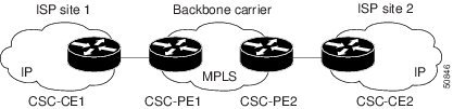
This section explains how a BGP/MPLS VPN service provider (backbone carrier) can provide a segment of its backbone network to a customer who is an ISP.
Consider the following example:
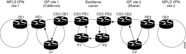
An ISP has two sites: one in California, the other in Maine. Each site is a point of presence (POP). The ISP wants to connect these sites using a VPN service provided by a backbone carrier. The figure below illustrates this situation.
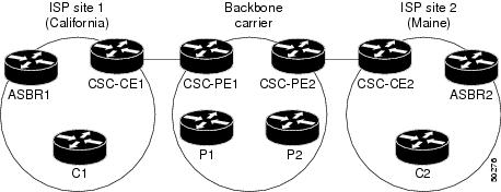
 Note | The CE routers in the figures are CE routers to the backbone carrier. However, they are PE routers to the customer carrier. |
In this example, only the backbone carrier uses MPLS. The customer carrier (ISP) uses only IP. As a result, the backbone carrier must carry all the Internet routes of the customer carrier, which could be as many as 100,000 routes. This poses a scalability problem for the backbone carrier. To solve the scalability problem, the backbone carrier is configured as follows:
- The backbone carrier allows only internal routes of the customer carrier (IGP routes) to be exchanged between the CE routers of the customer carrier and the PE routers of the backbone carrier.
- MPLS is enabled on the interface between the CE router of the customer carrier and the PE router of the backbone carrier.
Internal and external routes are differentiated this way:
The number of internal routes is much lower than the number of external routes. Restricting the routes between the CE routers of the customer carrier and the PE routers of the backbone carrier significantly reduces the number of routes that the PE router needs to maintain.
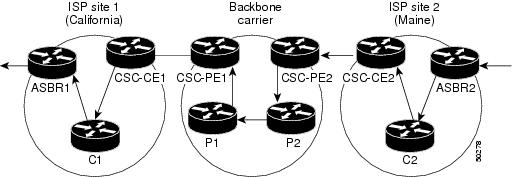
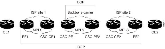
Because the PE routers do not have to carry external routes in the VRF routing table, they can use the incoming label in the packet to forward the customer carrier Internet traffic. Adding MPLS to the routers provides a consistent method of transporting packets from the customer carrier to the backbone carrier. MPLS allows the exchange of an MPLS label between the PE and the CE routers for every internal customer carrier route. The routers in the customer carrier have all the external routes either through internal Border Gateway Protocol (iBGP) or route redistribution to provide Internet connectivity. The figure below shows how information is exchanged when the network is configured in this manner.
In the figure below, routes are created between the backbone carrier and the customer carrier sites. ASBR2 receives an Internet route that originated outside the network. All routers in the ISP sites have all the external routes through IBGP connections among them.
The table below describes the process of establishing the route, which can be divided into two distinct steps:
- The backbone carrier propagates the IGP information of the customer carrier, which enables the customer carrier routers to reach all the customer carrier routers in the remote sites.
- Once the routers of the customer carriers in different sites are reachable, external routes can be propagated in the customer carrier sites, using IBGP without using the backbone carrier routers.
|
Step |
Description |
|---|---|
|
1 |
CSC-CE2 sends the internal routes within site 2 to CSC-PE2. The routes include the route to ASBR2. |
|
2 |
CSC-PE2 sends the routing information for site 2 to CSC-PE1, using MPLS VPN processes. CSC-PE1 gets one label (called L3), which is associated with the route to the VPN-IP address for ASBR2. CSC-PE1 gets another label (called L2), which is associated with the route to CSC-PE2. |
|
3 |
CSC-PE1 sends the routing information associated with internal routes from site 2 to CSC-CE1. CSC-PE1 also sends the label binding information. As a result, CSC-CE1 gets the route to ASBR2 with CSC-PE1 as the next hop. The label associated with that route is called L1. |
|
4 |
CSC-CE1 distributes the routing information through site 1. Every router in site 1 gets a route for every internal destination in site 2. Therefore, every router in site 1 can reach routers in site 2 and learn external routes through IBGP. |
|
5 |
ASBR2 receives an Internet route. |
|
6 |
The IBGP sessions exchange the external routing information of the ISP, including a route to the Internet. Every router in site 1 knows a route to the Internet, with ASBR2 as the next hop of that route. |
Customer Carrier Is a BGP MPLS VPN Service Provider
When a backbone carrier and the customer carrier both provide BGP/MPLS VPN services, the method of transporting data is different from when a customer carrier provides only ISP services. The following list highlights those differences:
- When a customer carrier provides BGP/MPLS VPN services, its external routes are VPN-IPv4 routes. When a customer carrier is an ISP, its external routes are IP routes.
- When a customer carrier provides BGP/MPLS VPN services, every site within the customer carrier must use MPLS. When a customer carrier is an ISP, the sites do not need to use MPLS.
The figure below shows how information is exchanged when MPLS VPN services reside on all customer carrier sites and on the backbone carrier.
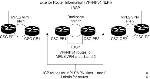
In the example shown in the figure below, routes are created between the backbone carrier and the customer carrier sites.
The table below describes the process of establishing the route.
|
Step |
Description |
|---|---|
|
1 |
CE2 sends all the internal routes within site 2 to CSC-PE2. |
|
2 |
CSC-PE2 sends the routing information for site 2 to CSC-PE1, using MPLS VPN processes. CSC-PE1 gets one label (called L3), which is associated with the route to the VPN-IP address for PE2. CSC-PE1 gets another label (called L2), which is associated with the route to CSC-PE2. |
|
3 |
CSC-PE1 sends the routing information associated with internal routes from site 2 to CSC-CE1. CSC-PE1 also sends the label binding information. As a result, CSC-CE1 gets the route to PE2 with CSC-PE1 as the next hop. The label associated with that route is called L1. |
|
4 |
CE1 distributes the routing and labeling information through site 1. Every router in site 1 gets a route for every internal destination in site 2. Therefore, PE1 can establish an MP-IBGP session with PE2. |
|
5 |
CE2 advertises the internal routes of MPLS VPN site 2 to PE2. |
|
6 |
PE2 allocates labels for all the VPN routes (regular MPLS VPN functionality) and advertises the labels to PE1, using MP-IBGP. |
|
7 |
PE1 can forward traffic from VPN site 1 that is destined for VPN site 2. |
How to Configure MPLS VPN CSC with LDP and IGP
- Configuring the Backbone Carrier Core
- Configuring the CSC-PE and CSC-CE Routers
- Verifying the Carrier Supporting Carrier Configuration
Configuring the Backbone Carrier Core
Configuring the backbone carrier core requires configuring connectivity and routing functions for the CSC core and the CSC-PE routers.
Configuring and verifying the CSC core (backbone carrier) involves the following tasks:
- Prerequisites
- Verifying IP Connectivity and LDP Configuration in the CSC Core
- Configuring VRFs for CSC-PE Routers
- Configuring Multiprotocol BGP for VPN Connectivity in the Backbone Carrier
Prerequisites
Before you configure a backbone carrier core, configure the following on the CSC core routers:
Verifying IP Connectivity and LDP Configuration in the CSC Core
Perform this task to verify IP connectivity and LDP configuration in the CSC core. For a configuration example for this task, see the Verifying IP Connectivity and LDP Configuration in the CSC Core.
1.
enable
2.
ping [protocol] {host-name |
system-address}
3.
trace [protocol] [destination]
4.
show mpls forwarding-table [network {mask |
length} |
labels
label [-label] |
interface
interface |
next-hop
address |
lsp-tunnel [tunnel-id]] [vrf
vrf-name] [detail]
5.
show mpls ldp discovery [vrf
vrf-name |
all]
6.
show mpls ldp neighbor [[vrf
vrf-name] [address |
interface] [detail] |
all]
7.
show ip cef [vrf
vrf-name] [network [mask]] [longer-prefixes] [detail]
8.
show mpls interfaces [[vrf
vrf-name] [interface] [detail] |all]
9.
show ip route
10.
disable
DETAILED STEPS
Troubleshooting Tips
You can use the ping and trace commands to verify complete MPLS connectivity in the core. You also get useful troubleshooting information from the additional show commands.
Configuring VRFs for CSC-PE Routers
Perform this task to configure VPN routing and forwarding (VRF) instances for the backbone carrier edge (CSC-PE) routers.
1.
enable
2.
configure terminal
3.
ip vrf
vrf-name
4.
rd
route-distinguisher
5.
route-target {import |
export |
both}
route-target-ext-community
6.
import map
route-map
7.
exit
8.
interface
type
number
9.
ip vrf forwarding
vrf-name
10.
end
DETAILED STEPS
Troubleshooting Tips
Enter a show ip vrf detail command and make sure the MPLS VPN is up and associated with the right interfaces.
Configuring Multiprotocol BGP for VPN Connectivity in the Backbone Carrier
Perform this task to configure Multiprotocol BGP (MP-BGP) connectivity in the backbone carrier.
1.
enable
2.
configure terminal
3.
router bgp
as-number
4.
no bgp default ipv4-unicast
5.
neighbor {ip-address |
peer-group-name}
remote-as
as-number
6.
neighbor {ip-address |
peer-group-name}
update-source
interface-type
7.
address-family vpnv4 [unicast]
8.
neighbor {ip-address |
peer-group-name}
send-community extended
9.
neighbor {ip-address |
peer-group-name}
activate
10.
end
DETAILED STEPS
Troubleshooting Tips
You can enter a show ip bgp neighbor command to verify that the neighbors are up and running. If this command generates an error message, enter a debug ip bgp x.x.x.x events command, where x.x.x.x is the IP address of the neighbor.
Configuring the CSC-PE and CSC-CE Routers
To enable the CSC-PE and CSC-CE routers to distribute routes and MPLS labels, perform the following tasks:
- Prerequisites
- Configuring LDP on the CSC-PE and CSC-CE Routers
- Enabling MPLS Encapsulation on the CSC-PE and CSC-CE Routers
Prerequisites
Before you configure the CSC-PE and CSC-CE routers, you must configure an IGP on the CSC-PE and CSC-CE routers. A routing protocol is required between the PE and CE routers that connect the backbone carrier to the customer carrier. The routing protocol enables the customer carrier to exchange IGP routing information with the backbone carrier. Use the same routing protocol that the customer carrier uses. You can choose RIP, OSPF, or static routing as the routing protocol. BGP is not supported. For the configuration steps, see Configuring MPLS Layer 3 VPNs .
Configuring LDP on the CSC-PE and CSC-CE Routers
MPLS LDP is required between the PE and CE routers that connect the backbone carrier to the customer carrier. You can configure LDP as the default label distribution protocol for the entire router or just for the PE-to-CE interface for VRF.
1.
enable
2.
configure terminal
3.
mpls label protocol ldp
4.
interface
type
number
5.
mpls label protocol ldp
6.
exit
DETAILED STEPS
Enabling MPLS Encapsulation on the CSC-PE and CSC-CE Routers
Every packet that crosses the backbone carrier must be encapsulated, so that the packet includes MPLS labels. You can enable MPLS encapsulation for the entire router or just on the interface of the PE or CE router. To enable the encapsulation of packets, perform the following task.
1.
enable
2.
configure terminal
3.
mpls ip
4.
interface
type
number
5.
mpls ip
6.
exit
DETAILED STEPS
Verifying the Carrier Supporting Carrier Configuration
The following commands verify the status of LDP sessions that were configured between the backbone carrier and customer carrier. Now the customer carrier ISP sites appear as a VPN customer to the backbone carrier.
1.
show mpls ldp discovery vrf
vrf-name
2.
show mpls ldp discovery all
DETAILED STEPS
Configuration Examples for MPLS VPN CSC with LDP and IGP
- MPLS VPN CSC Network with a Customer Who Is an ISP Example
- MPLS VPN CSC Network with a Customer Who Is an MPLS VPN Provider Example
- MPLS VPN CSC Network That Contains Route Reflectors Example
- MPLS VPN CSC Network with a Customer Who Has VPNs at the Network Edge Example
MPLS VPN CSC Network with a Customer Who Is an ISP Example
The figure below shows a carrier supporting carrier network configuration where the customer carrier is an ISP. The customer carrier has two sites, each of which is a POP. The customer carrier connects these sites using a VPN service provided by the backbone carrier. The backbone carrier uses MPLS. The ISP sites use IP. To enable packet transfer between the ISP sites and the backbone carrier, the CE routers that connect the ISPs to the backbone carrier run MPLS.
The following examples show the configuration of each router in the carrier supporting carrier network. OSPF is used to connect the customer carrier to the backbone carrier.
CSC-CE1 Configuration
mpls label protocol ldp
!
interface Loopback0
 ip address 10.14.14.14 255.255.255.255
 no ip directed-broadcast
 no ip route-cache
 no ip mroute-cache
!
interface ATM1/0
 no ip address
 no ip directed-broadcast
 no ip mroute-cache
 atm clock INTERNAL
 atm sonet stm-1
 no atm enable-ilmi-trap
 no atm ilmi-keepalive
!
interface ATM1/0.1 point-to-point
 ip address 10.0.0.2 255.0.0.0
 no ip directed-broadcast
 atm pvc 101 0 51 aal5snap
 no atm enable-ilmi-trap
 mpls label protocol ldp
 mpls ip
!
interface ATM2/0
 no ip address
 no ip directed-broadcast
 no ip mroute-cache
 atm clock INTERNAL
 atm sonet stm-1
 no atm enable-ilmi-trap
 no atm ilmi-keepalive
!
interface ATM2/0.1 point-to-point
 ip address 10.0.0.2 255.0.0.0
 no ip directed-broadcast
 atm pvc 100 0 50 aal5snap
 no atm enable-ilmi-trap
 mpls label protocol ldp
 mpls ip
!
router ospf 200
 log-adjacency-changes
 redistribute connected subnets
 network 10.14.14.14 0.0.0.0 area 200
 network 10.15.0.0 0.255.255.255 area 200
 network 10.16.0.0 0.255.255.255 area 200
CSC-PE1 Configuration
ip cef distributed
!
ip vrf vpn1
 rd 100:0
 route-target export 100:0
 route-target import 100:0
mpls label protocol ldp
no mpls aggregate-statistics
!
interface Loopback0
 ip address 10.11.11.11 255.255.255.255
 no ip directed-broadcast
 no ip route-cache
 no ip mroute-cache
!
interface Loopback100
 ip vrf forwarding vpn1
 ip address 10.19.19.19 255.255.255.255
 no ip directed-broadcast
!
interface ATM1/1/0
 no ip address
 no ip directed-broadcast
 no ip route-cache distributed
 atm clock INTERNAL
 no atm enable-ilmi-trap
 no atm ilmi-keepalive
!
interface ATM1/1/0.1
 ip address 10.0.0.1 255.0.0.0
 no ip directed-broadcast
 atm pvc 100 0 50 aal5snap
 no atm enable-ilmi-trap
 mpls label protocol ldp
 mpls ip
!
interface ATM3/0/0
 no ip address
 no ip directed-broadcast
 no ip route-cache distributed
 atm clock INTERNAL
 atm sonet stm-1
 no atm enable-ilmi-trap
 no atm ilmi-keepalive
!
interface ATM3/0/0.1 point-to-point
 ip vrf forwarding vpn1
 ip address 10.0.0.1 255.0.0.0
 no ip directed-broadcast
 atm pvc 101 0 51 aal5snap
 no atm enable-ilmi-trap
 mpls label protocol ldp
 mpls ip
!
router ospf 100
 log-adjacency-changes
 passive-interface ATM3/0/0.1
 passive-interface Loopback100
 network 10.11.11.11 0.0.0.0 area 100
 network 10.0.0.0 0.255.255.255 area 100
!
router ospf 200 vrf vpn1
 log-adjacency-changes
 redistribute bgp 100 metric-type 1 subnets
 network 10.19.19.19 0.0.0.0 area 200
 network 10.0.0.0 0.255.255.255 area 200
!
router bgp 100
 bgp log-neighbor-changes
 timers bgp 10 30
 neighbor 10.12.12.12 remote-as 100
 neighbor 10.12.12.12 update-source Loopback0
 !
 address-family ipv4
 neighbor 10.12.12.12 activate
 neighbor 10.12.12.12 send-community extended
 no synchronization
 exit-address-family
 !
 address-family vpnv4
 neighbor 10.12.12.12 activate
 neighbor 10.12.12.12 send-community extended
 exit-address-family
 !
 address-family ipv4 vrf vpn1
 redistribute ospf 200 match internal external 1 external 2
 no auto-summary
 no synchronization
 exit-address-family
CSC-PE2 Configuration
ip cef distributed
!
ip vrf vpn1
 rd 100:0
 route-target export 100:0
 route-target import 100:0
mpls label protocol ldp
no mpls aggregate-statistics
!
interface Loopback0
 ip address 10.12.12.12 255.255.255.255
 no ip directed-broadcast
 no ip route-cache
 no ip mroute-cache
!
interface Loopback100
 ip vrf forwarding vpn1
 ip address 10.20.20.20 255.255.255.255
 no ip directed-broadcast
!
interface ATM0/1/0
 no ip address
 no ip directed-broadcast
 no ip route-cache distributed
 no ip mroute-cache
 atm clock INTERNAL
 atm sonet stm-1
 no atm enable-ilmi-trap
 no atm ilmi-keepalive
!
interface ATM0/1/0.1 point-to-point
 ip address 10.0.0.2 255.0.0.0
 no ip directed-broadcast
 atm pvc 100 0 50 aal5snap
 no atm enable-ilmi-trap
 mpls label protocol ldp
 mpls ip
!
interface ATM3/0/0
 no ip address
 no ip directed-broadcast
 no ip route-cache distributed
 no ip mroute-cache
 atm clock INTERNAL
 atm sonet stm-1
 no atm enable-ilmi-trap
 no atm ilmi-keepalive
!
interface ATM3/0/0.1 point-to-point
 ip vrf forwarding vpn1
 ip address 10.0.0.1 255.0.0.0
 no ip directed-broadcast
 atm pvc 100 0 50 aal5snap
 no atm enable-ilmi-trap
 mpls label protocol ldp
 mpls ip
!
router ospf 100
 log-adjacency-changes
 passive-interface ATM3/0/0.1
 passive-interface Loopback100
 network 10.12.12.12 0.0.0.0 area 100
 network 10.0.0.0 0.255.255.255 area 100
!
router ospf 200 vrf vpn1
 log-adjacency-changes
 redistribute bgp 100 metric-type 1 subnets
 network 10.20.20.20 0.0.0.0 area 200
 network 10.0.0.0 0.255.255.255 area 200
!
router bgp 100
 bgp log-neighbor-changes
 timers bgp 10 30
 neighbor 10.11.11.11 remote-as 100
 neighbor 10.11.11.11 update-source Loopback0
 !
 address-family ipv4
 neighbor 10.11.11.11 activate
 neighbor 10.11.11.11 send-community extended
 no synchronization
 exit-address-family
 !
 address-family vpnv4
 neighbor 10.11.11.11 activate
 neighbor 10.11.11.11 send-community extended
 exit-address-family
 !
 address-family ipv4 vrf vpn1
 redistribute ospf 200 match internal external 1 external 2
 no auto-summary
 no synchronization
 exit-address-family
CSC-CE2 Configuration
ip cef
!
mpls label protocol ldp
!
interface Loopback0
 ip address 10.16.16.16 255.255.255.255
 no ip directed-broadcast
 no ip route-cache
 no ip mroute-cache
!
interface ATM1/0
 no ip address
 no ip directed-broadcast
 no ip mroute-cache
 atm clock INTERNAL
 atm sonet stm-1
 no atm enable-ilmi-trap
 no atm ilmi-keepalive
!
interface ATM1/0.1 point-to-point
 ip address 10.0.0.2 255.0.0.0
 no ip directed-broadcast
 atm pvc 100 0 50 aal5snap
 no atm enable-ilmi-trap
 mpls label protocol ldp
 mpls ip
!
interface ATM5/0
 no ip address
 no ip directed-broadcast
 no ip mroute-cache
 atm clock INTERNAL
 atm sonet stm-1
 no atm enable-ilmi-trap
 no atm ilmi-keepalive
!
interface ATM5/0.1 point-to-point
 ip address 10.0.0.2 255.0.0.0
 no ip directed-broadcast
 atm pvc 100 0 50 aal5snap
 no atm enable-ilmi-trap
 mpls label protocol ldp
 mpls ip
!
router ospf 200
 log-adjacency-changes
 redistribute connected subnets
 network 10.16.16.16 0.0.0.0 area 200
 network 10.0.0.0 0.255.255.255 area 200
 network 10.0.0.0 0.255.255.255 area 200
MPLS VPN CSC Network with a Customer Who Is an MPLS VPN Provider Example
The figure below shows a carrier supporting carrier network configuration where the customer carrier is an MPLS VPN provider. The customer carrier has two sites. The backbone carrier and the customer carrier use MPLS. The IBGP sessions exchange the external routing information of the ISP.
The following configuration examples show the configuration of each router in the carrier supporting carrier network. OSPF is the protocol used to connect the customer carrier to the backbone carrier.
- CE1 Configuration
- PE1 Configuration
- CSC-CE1 Configuration
- CSC-PE1 Configuration
- CSC-PE2 Configuration
- CSC-CE2 Configuration
- PE2 Configuration
- CE2 Configuration
CE1 Configuration
ip cef
!
interface Loopback0
 ip address 10.17.17.17 255.255.255.255
 no ip directed-broadcast
!
interface Ethernet0/1
 ip address 10.0.0.2 255.0.0.0
 no ip directed-broadcast
!
router ospf 300
 log-adjacency-changes
 redistribute bgp 300 subnets
 passive-interface Ethernet0/1
 network 10.17.17.17 0.0.0.0 area 300
!
router bgp 300
 no synchronization
 bgp log-neighbor-changes
 timers bgp 10 30
 redistribute connected
 redistribute ospf 300 match internal external 1 external 2
 neighbor 10.0.0.1 remote-as 200
 neighbor 10.0.0.1 advertisement-interval 5
 no auto-summary
PE1 Configuration
ip cef
!
ip vrf vpn2
 rd 200:1
 route-target export 200:1
 route-target import 200:1
mpls label protocol ldp
!
interface Loopback0
 ip address 10.13.13.13 255.255.255.255
 no ip directed-broadcast
 no ip route-cache
 no ip mroute-cache
!
interface ATM1/0
 no ip address
 no ip directed-broadcast
 no ip mroute-cache
 atm clock INTERNAL
 atm sonet stm-1
 no atm enable-ilmi-trap
 no atm ilmi-keepalive
!
interface ATM1/0.1 point-to-point
 ip address 10.0.0.1 255.0.0.0
 no ip directed-broadcast
 atm pvc 100 0 50 aal5snap
 no atm enable-ilmi-trap
 mpls label protocol ldp
 mpls ip
!
interface Ethernet3/0
 ip vrf forwarding vpn2
 ip address 10.0.0.1 255.0.0.0
 no ip directed-broadcast
 no ip mroute-cache
!
router ospf 200
 log-adjacency-changes
 redistribute connected subnets
 passive-interface Ethernet3/0
 network 10.13.13.13 0.0.0.0 area 200
 network 10.0.0.0 0.255.255.255 area 200
!
router bgp 200
 no bgp default ipv4-unicast
 bgp log-neighbor-changes
 timers bgp 10 30
 neighbor 10.15.15.15 remote-as 200
 neighbor 10.15.15.15 update-source Loopback0
 !
 address-family ipv4
 neighbor 10.15.15.15 activate
 neighbor 10.15.15.15 send-community extended
 no synchronization
 exit-address-family
 !
 address-family vpnv4
 neighbor 10.15.15.15 activate
 neighbor 10.15.15.15 send-community extended
 exit-address-family
 !
 address-family ipv4 vrf vpn2
 neighbor 10.0.0.2 remote-as 300
 neighbor 10.0.0.2 activate
 neighbor 10.0.0.2 as-override
 neighbor 10.0.0.2 advertisement-interval 5
 no auto-summary
 no synchronization
 exit-address-family
CSC-CE1 Configuration
mpls label protocol ldp
!
interface Loopback0
 ip address 10.14.14.14 255.255.255.255
 no ip directed-broadcast
 no ip route-cache
 no ip mroute-cache
!
interface ATM1/0
 no ip address
 no ip directed-broadcast
 no ip mroute-cache
 atm clock INTERNAL
 atm sonet stm-1
 no atm enable-ilmi-trap
 no atm ilmi-keepalive
!
interface ATM1/0.1 point-to-point
 ip address 10.0.0.2 255.0.0.0
 no ip directed-broadcast
 atm pvc 101 0 51 aal5snap
 no atm enable-ilmi-trap
 mpls label protocol ldp
 mpls ip
!
interface ATM2/0
 no ip address
 no ip directed-broadcast
 no ip mroute-cache
 atm clock INTERNAL
 atm sonet stm-1
 no atm enable-ilmi-trap
 no atm ilmi-keepalive
!
interface ATM2/0.1 point-to-point
 ip address 10.0.0.2 255.0.0.0
 no ip directed-broadcast
 atm pvc 100 0 50 aal5snap
 no atm enable-ilmi-trap
 mpls label protocol ldp
 mpls ip
!
router ospf 200
 log-adjacency-changes
 redistribute connected subnets
 network 10.14.14.14 0.0.0.0 area 200
 network 10.0.0.0 0.255.255.255 area 200
 network 10.0.0.0 0.255.255.255 area 200
CSC-PE1 Configuration
ip cef distributed
!
ip vrf vpn1
 rd 100:0
 route-target export 100:0
 route-target import 100:0
mpls label protocol ldp
no mpls aggregate-statistics
!
interface Loopback0
 ip address 11.11.11.11 255.255.255.255
 no ip directed-broadcast
 no ip route-cache
 no ip mroute-cache
!
interface Loopback100
 ip vrf forwarding vpn1
 ip address 10.19.19.19 255.255.255.255
 no ip directed-broadcast
!
interface ATM1/1/0
 no ip address
 no ip directed-broadcast
 no ip route-cache distributed
 atm clock INTERNAL
 no atm enable-ilmi-trap
 no atm ilmi-keepalive
!
interface ATM1/1/0.1 point-to-point
 ip address 10.0.0.1 255.0.0.0
 no ip directed-broadcast
 atm pvc 100 0 50 aal5snap
 no atm enable-ilmi-trap
 mpls label protocol ldp
 mpls ip
!
interface ATM3/0/0
 no ip address
 no ip directed-broadcast
 no ip route-cache distributed
 atm clock INTERNAL
 atm sonet stm-1
 no atm enable-ilmi-trap
 no atm ilmi-keepalive
!
interface ATM3/0/0.1 point-to-point
 ip vrf forwarding vpn1
 ip address 10.0.0.1 255.0.0.0
 no ip directed-broadcast
 atm pvc 101 0 51 aal5snap
 no atm enable-ilmi-trap
 mpls label protocol ldp
 mpls ip
!
router ospf 100
 log-adjacency-changes
 passive-interface ATM3/0/0.1
 passive-interface Loopback100
 network 10.11.11.11 0.0.0.0 area 100
 network 10.0.0.0 0.255.255.255 area 100
!
router ospf 200 vrf vpn1
 log-adjacency-changes
 redistribute bgp 100 metric-type 1 subnets
 network 10.19.19.19 0.0.0.0 area 200
 network 10.0.0.0 0.255.255.255 area 200
!
router bgp 100
 bgp log-neighbor-changes
 timers bgp 10 30
 neighbor 10.12.12.12 remote-as 100
 neighbor 10.12.12.12 update-source Loopback0
 !
 address-family ipv4
 neighbor 10.12.12.12 activate
 neighbor 10.12.12.12 send-community extended
 no synchronization
 exit-address-family
 !
 address-family vpnv4
 neighbor 10.12.12.12 activate
 neighbor 10.12.12.12 send-community extended
 exit-address-family
 !
 address-family ipv4 vrf vpn1
 redistribute ospf 200 match internal external 1 external 2
 no auto-summary
 no synchronization
 exit-address-family
CSC-PE2 Configuration
ip cef distributed
!
ip vrf vpn1
 rd 100:0
 route-target export 100:0
 route-target import 100:0
mpls label protocol ldp
no mpls aggregate-statistics
!
interface Loopback0
 ip address 10.12.12.12 255.255.255.255
 no ip directed-broadcast
 no ip route-cache
 no ip mroute-cache
!
interface Loopback100
 ip vrf forwarding vpn1
 ip address 10.20.20.20 255.255.255.255
 no ip directed-broadcast
!
interface ATM0/1/0
 no ip address
 no ip directed-broadcast
 no ip route-cache distributed
 no ip mroute-cache
 atm clock INTERNAL
 atm sonet stm-1
 no atm enable-ilmi-trap
 no atm ilmi-keepalive
!
interface ATM0/1/0.1 point-to-point
 ip address 10.0.0.2 255.0.0.0
 no ip directed-broadcast
 atm pvc 100 0 50 aal5snap
 no atm enable-ilmi-trap
 mpls label protocol ldp
 mpls ip
!
interface ATM3/0/0
 no ip address
 no ip directed-broadcast
 no ip route-cache distributed
 no ip mroute-cache
 atm clock INTERNAL
 atm sonet stm-1
 no atm enable-ilmi-trap
 no atm ilmi-keepalive
!
interface ATM3/0/0.1 point-to-point
 ip vrf forwarding vpn1
 ip address 10.0.0.1 255.0.0.0
 no ip directed-broadcast
 atm pvc 100 0 50 aal5snap
 no atm enable-ilmi-trap
 mpls label protocol ldp
 mpls ip
!
router ospf 100
 log-adjacency-changes
 passive-interface ATM3/0/0.1
 passive-interface Loopback100
 network 10.12.12.12 0.0.0.0 area 100
 network 10.0.0.0 0.255.255.255 area 100
!
router ospf 200 vrf vpn1
 log-adjacency-changes
 redistribute bgp 100 metric-type 1 subnets
 network 10.20.20.20 0.0.0.0 area 200
 network 10.0.0.0 0.255.255.255 area 200
!
router bgp 100
 bgp log-neighbor-changes
 timers bgp 10 30
 neighbor 10.11.11.11 remote-as 100
 neighbor 10.11.11.11 update-source Loopback0
 !
 address-family ipv4
 neighbor 10.11.11.11 activate
 neighbor 10.11.11.11 send-community extended
 no synchronization
 exit-address-family
 !
 address-family vpnv4
 neighbor 10.11.11.11 activate
 neighbor 10.11.11.11 send-community extended
 exit-address-family
 !
 address-family ipv4 vrf vpn1
 redistribute ospf 200 match internal external 1 external 2
 no auto-summary
 no synchronization
 exit-address-family
CSC-CE2 Configuration
ip cef
!
mpls label protocol ldp
!
interface Loopback0
 ip address 10.16.16.16 255.255.255.255
 no ip directed-broadcast
 no ip route-cache
 no ip mroute-cache
!
interface ATM1/0
 no ip address
 no ip directed-broadcast
 no ip mroute-cache
 atm clock INTERNAL
 atm sonet stm-1
 no atm enable-ilmi-trap
 no atm ilmi-keepalive
!
interface ATM1/0.1 point-to-point
 ip address 10.0.0.2 255.0.0.0
 no ip directed-broadcast
 atm pvc 100 0 50 aal5snap
 no atm enable-ilmi-trap
 mpls label protocol ldp
 mpls ip
!
interface ATM5/0
 no ip address
 no ip directed-broadcast
 no ip mroute-cache
 atm clock INTERNAL
 atm sonet stm-1
 no atm enable-ilmi-trap
 no atm ilmi-keepalive
!
interface ATM5/0.1 point-to-point
 ip address 10.0.0.2 255.0.0.0
 no ip directed-broadcast
 atm pvc 100 0 50 aal5snap
 no atm enable-ilmi-trap
 mpls label protocol ldp
 mpls ip
!
router ospf 200
 log-adjacency-changes
 redistribute connected subnets
 network 10.16.16.16 0.0.0.0 area 200
 network 10.0.0.0 0.255.255.255 area 200
 network 10.0.0.0 0.255.255.255 area 200
PE2 Configuration
ip cef
ip cef accounting non-recursive
!
ip vrf vpn2
 rd 200:1
 route-target export 200:1
 route-target import 200:1
mpls label protocol ldp
!
interface Loopback0
 ip address 10.15.15.15 255.255.255.255
 no ip directed-broadcast
!
interface Ethernet3/0
 ip vrf forwarding vpn2
 ip address 10.0.0.1 255.0.0.0
 no ip directed-broadcast
!
interface ATM5/0
 no ip address
 no ip directed-broadcast
 atm clock INTERNAL
 atm sonet stm-1
 no atm enable-ilmi-trap
 no atm ilmi-keepalive
!
interface ATM5/0.1 point-to-point
 ip address 10.0.0.1 255.0.0.0
 no ip directed-broadcast
 atm pvc 100 0 50 aal5snap
 no atm enable-ilmi-trap
 mpls label protocol ldp
 mpls ip
!
router ospf 200
 log-adjacency-changes
 redistribute connected subnets
 passive-interface Ethernet3/0
 network 10.15.15.15 0.0.0.0 area 200
 network 10.0.0.0 0.255.255.255 area 200
!
router bgp 200
 no bgp default ipv4-unicast
 bgp log-neighbor-changes
 timers bgp 10 30
 neighbor 10.13.13.13 remote-as 200
 neighbor 10.13.13.13 update-source Loopback0
 !
 address-family ipv4
 neighbor 10.13.13.13 activate
 neighbor 10.13.13.13 send-community extended
 no synchronization
 exit-address-family
 !
 address-family vpnv4
 neighbor 10.13.13.13 activate
 neighbor 10.13.13.13 send-community extended
 exit-address-family
 !
 address-family ipv4 vrf vpn2
 neighbor 10.0.0.2 remote-as 300
 neighbor 10.0.0.2 activate
 neighbor 10.0.0.2 as-override
 neighbor 10.0.0.2 advertisement-interval 5
 no auto-summary
 no synchronization
 exit-address-family
CE2 Configuration
ip cef
!
interface Loopback0
 ip address 10.18.18.18 255.255.255.255
 no ip directed-broadcast
!
interface Ethernet0/1
 ip address 10.0.0.2 255.0.0.0
 no ip directed-broadcast
!
router ospf 300
 log-adjacency-changes
 redistribute bgp 300 subnets
 passive-interface Ethernet0/1
 network 10.18.18.18 0.0.0.0 area 300
!
router bgp 300
 no synchronization
 bgp log-neighbor-changes
 timers bgp 10 30
 redistribute connected
 redistribute ospf 300 match internal external 1 external 2
 neighbor 10.0.0.1 remote-as 200
 neighbor 10.0.0.1 advertisement-interval 5
 no auto-summary
MPLS VPN CSC Network That Contains Route Reflectors Example
The figure below shows a carrier supporting carrier network configuration that contains route reflectors. The customer carrier has two sites.
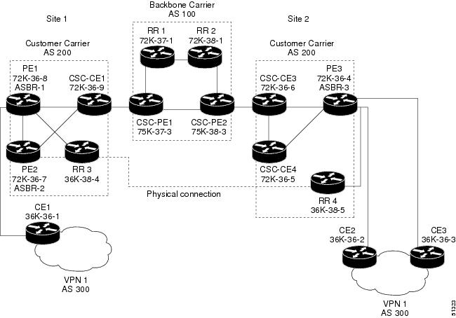
Note | A connection between route reflectors (RRs) is not necessary. |
The following configuration examples show the configuration of each router in the carrier supporting carrier network. Note the following:
- Backbone Carrier Configuration
- Customer Carrier Site 1 Configuration
- Customer Carrier Site 2 Configuration
Backbone Carrier Configuration
- Route Reflector 1 (72K-37-1) Configuration
- Route Reflector 2 (72K-38-1) Configuration
- CSC-PE1 (75K-37-3) Configuration
- CSC-PE2 (75K-38-3) Configuration
Route Reflector 1 (72K-37-1) Configuration
interface Loopback0
 ip address 10.13.13.13 255.255.255.255
 no ip directed-broadcast
 no ip route-cache
 no ip mroute-cache
!
interface ATM1/0
 no ip address
 no ip directed-broadcast
 atm clock INTERNAL
 no atm enable-ilmi-trap
 no atm ilmi-keepalive
!
interface ATM1/0.1 mpls
ip address 10.0.0.2 255.0.0.0
 no ip directed-broadcast
 no atm enable-ilmi-trap
 mpls label protocol ldp
 mpls atm vpi 2-5
 mpls ip
!
interface ATM1/1
 no ip address
 no ip directed-broadcast
 atm clock INTERNAL
 no atm enable-ilmi-trap
 no atm ilmi-keepalive
!
interface ATM1/1.1 mpls
 ip address 10.0.0.1 255.0.0.0
 no ip directed-broadcast
 no atm enable-ilmi-trap
 mpls label protocol ldp
 mpls atm vpi 2-5
 mpls ip
!
router ospf 100
 auto-cost reference-bandwidth 10000
 network 10.0.0.0 0.255.255.255 area 100
 network 10.1.0.0 0.255.255.255 area 100
 network 10.2.0.0 0.255.255.255 area 100
!
router bgp 100
 no synchronization
 no bgp default ipv4-unicast
 bgp cluster-id 1
 redistribute static
 neighbor 10.15.15.15 remote-as 100
 neighbor 10.15.15.15 update-source Loopback0
 neighbor 10.16.16.16 remote-as 100
 neighbor 10.16.16.16 update-source Loopback0
 !
 address-family ipv4 vrf vpn1
 no auto-summary
 no synchronization
 exit-address-family
 !
 address-family vpnv4
 neighbor 10.15.15.15 activate
 neighbor 10.15.15.15 route-reflector-client
 neighbor 10.15.15.15 send-community extended
 neighbor 10.16.16.16 activate
 neighbor 10.16.16.16 route-reflector-client
 neighbor 10.16.16.16 send-community extended
 bgp scan-time import 5
 exit-address-family
Route Reflector 2 (72K-38-1) Configuration
interface Loopback0
 ip address 10.14.14.14 255.255.255.255
 no ip directed-broadcast
 no ip mroute-cache
!
interface ATM1/0
 no ip address
 no ip directed-broadcast
 atm clock INTERNAL
 no atm enable-ilmi-trap
 no atm ilmi-keepalive
!
interface ATM1/0.1 mpls
 ip address 10.0.0.1 255.0.0.0
no ip directed-broadcast
 no atm enable-ilmi-trap
 mpls label protocol ldp
 mpls atm vpi 2-5
 mpls ip
!
interface ATM1/1
 no ip address
 no ip directed-broadcast
 atm clock INTERNAL
 no atm enable-ilmi-trap
 no atm ilmi-keepalive
!
interface ATM1/1.1 mpls
 ip address 10.0.0.2 255.0.0.0
 no ip directed-broadcast
 no atm enable-ilmi-trap
 mpls label protocol ldp
 mpls atm vpi 2-5
 mpls ip
!
router ospf 100
 auto-cost reference-bandwidth 10000
 network 10.0.0.0 0.255.255.255 area 100
 network 10.1.0 0.255.255.255 area 100
 network 10.2.0.0 0.255.255.255 area 100
!
router bgp 100
 no synchronization
 no bgp default ipv4-unicast
 bgp cluster-id 1
 redistribute static
 neighbor 10.15.15.15 remote-as 100
 neighbor 10.15.15.15 update-source Loopback0
 neighbor 10.16.16.16 remote-as 100
 neighbor 10.16.16.16 update-source Loopback0
 !
 address-family ipv4 vrf vpn1
 no auto-summary
 no synchronization
 exit-address-family
 !
 address-family vpnv4
 neighbor 10.15.15.15 activate
 neighbor 10.15.15.15 route-reflector-client
 neighbor 10.15.15.15 send-community extended
 neighbor 10.16.16.16 activate
 neighbor 10.16.16.16 route-reflector-client
 neighbor 10.16.16.16 send-community extended
 bgp scan-time import 5
 exit-address-family
CSC-PE1 (75K-37-3) Configuration
ip cef distributed
!
ip vrf vpn1
 rd 100:1
 route-target export 100:1
 route-target import 100:1
!
interface Loopback0
 ip address 10.15.15.15 255.255.255.255
 no ip directed-broadcast
!
interface Loopback1
 ip vrf forwarding vpn1
 ip address 10.18.18.18 255.255.255.255
 no ip directed-broadcast
!
interface Ethernet0/0/1
 ip vrf forwarding vpn1
 ip address 10.0.0.2 255.0.0.0
 no ip directed-broadcast
 no ip route-cache distributed
 mpls label protocol ldp
 mpls ip
!
interface ATM1/1/0
 no ip address
 no ip directed-broadcast
 no ip route-cache distributed
 atm clock INTERNAL
 atm sonet stm-1
 no atm enable-ilmi-trap
 no atm ilmi-keepalive
!
interface ATM1/1/0.1 mpls
 ip address 10.0.0.1 255.0.0.0
 no ip directed-broadcast
 no atm enable-ilmi-trap
 mpls label protocol ldp
 mpls atm vpi 2-5
 mpls ip
!
interface ATM3/0/0
 no ip address
 no ip directed-broadcast
 no ip route-cache distributed
 atm clock INTERNAL
 atm sonet stm-1
 no atm enable-ilmi-trap
 no atm ilmi-keepalive
!
interface ATM3/0/0.1 point-to-point
 ip vrf forwarding vpn1
 ip address 10.0.0.2 255.0.0.0
 no ip directed-broadcast
 atm pvc 100 6 32 aal5snap
 no atm enable-ilmi-trap
 mpls label protocol ldp
 mpls ip
!
interface ATM3/1/0
 no ip address
 no ip directed-broadcast
 no ip route-cache distributed
 atm clock INTERNAL
 atm sonet stm-1
 no atm enable-ilmi-trap
 no atm ilmi-keepalive
!
interface ATM3/1/0.1 mpls
 ip address 10.0.0.1 255.0.0.0
 no ip directed-broadcast
 no atm enable-ilmi-trap
 mpls label protocol ldp
 mpls atm vpi 2-5
 mpls ip
!
router ospf 100
 auto-cost reference-bandwidth 10000
 network 10.0.0.0 0.255.255.255 area 100
 network 10.1.0.0 0.255.255.255 area 100
 network 10.2.0.0 0.255.255.255 area 100
 network 10.3.0.0 0.255.255.255 area 100
 network 10.4.0.0 0.255.255.255 area 100
!
router ospf 1 vrf vpn1
 redistribute bgp 100 metric-type 1 subnets
 network 10.0.0.0 0.255.255.255 area 101
 network 10.0.0.0 0.255.255.255 area 101
 network 10.0.0.0 0.255.255.255 area 101
 network 10.0.0.0 0.255.255.255 area 101
!
router bgp 100
 no bgp default ipv4-unicast
 bgp log-neighbor-changes
 neighbor 10.13.13.13 remote-as 100
 neighbor 10.13.13.13 update-source Loopback0
 neighbor 10.14.14.14 remote-as 100
 neighbor 10.14.14.14 update-source Loopback0
 !
 address-family ipv4
 redistribute static
 no synchronization
 exit-address-family
 !
 address-family vpnv4
 neighbor 10.13.13.13 activate
 neighbor 10.13.13.13 send-community extended
 neighbor 10.14.14.14 activate
 neighbor 10.14.14.14 send-community extended
 exit-address-family
 !
 address-family ipv4 vrf vpn1
 redistribute ospf 1 match internal external 1 external 2
 no auto-summary
 no synchronization
 exit-address-family
CSC-PE2 (75K-38-3) Configuration
ip cef distributed
!
ip vrf vpn1
 rd 100:1
 route-target export 100:1
 route-target import 100:1
!
interface Loopback0
 ip address 10.16.16.16 255.255.255.255
 no ip directed-broadcast
!
interface Loopback1
 ip vrf forwarding vpn1
 ip address 10.20.20.20 255.255.255.255
 no ip directed-broadcast
!
interface ATM0/1/0
 no ip address
 no ip directed-broadcast
 no ip route-cache distributed
 atm clock INTERNAL
atm sonet stm-1
 no atm enable-ilmi-trap
 no atm ilmi-keepalive
!
interface ATM0/1/0.1 mpls
 ip address 10.0.0.2 255.0.0.0
 no ip directed-broadcast
 no atm enable-ilmi-trap
 mpls label protocol ldp
 mpls atm vpi 2-5
 mpls ip
!
interface ATM2/1/0
 no ip address
 no ip directed-broadcast
 no ip route-cache distributed
 atm clock INTERNAL
 atm sonet stm-1
 no atm enable-ilmi-trap
 no atm ilmi-keepalive
!
interface ATM2/1/0.1 mpls
 ip address 10.0.0.2 255.0.0.0
 no ip directed-broadcast
 no atm enable-ilmi-trap
 mpls label protocol ldp
 mpls atm vpi 2-5
 mpls ip
!
interface ATM3/0/0
 no ip address
 no ip directed-broadcast
 no ip route-cache distributed
 atm clock INTERNAL
 atm sonet stm-1
 no atm enable-ilmi-trap
 no atm ilmi-keepalive
!
interface ATM3/0/0.1 point-to-point
 ip vrf forwarding vpn1
 ip address 10.0.0.1 255.0.0.0
 no ip directed-broadcast
 atm pvc 100 6 32 aal5snap
 no atm enable-ilmi-trap
 mpls label protocol ldp
 mpls ip
!
interface ATM3/1/0
 no ip address
 no ip directed-broadcast
no ip route-cache distributed
 atm clock INTERNAL
 atm sonet stm-1
 no atm enable-ilmi-trap
 no atm ilmi-keepalive
!
interface ATM3/1/0.1 point-to-point
 ip vrf forwarding vpn1
 ip address 10.0.0.1 255.0.0.0
 no ip directed-broadcast
 atm pvc 101 6 33 aal5snap
 no atm enable-ilmi-trap
 mpls label protocol ldp
 mpls ip
!
router ospf 100
 auto-cost reference-bandwidth 10000
 network 10.0.0.0 0.255.255.255 area 100
 network 10.0.0.0 0.255.255.255 area 100
 network 10.0.0.0 0.255.255.255 area 100
 network 10.0.0.0 0.255.255.255 area 100
 network 10.0.0.0 0.255.255.255 area 100
!
router ospf 1 vrf vpn1
 redistribute bgp 100 metric-type 1 subnets
 network 10.0.0.0 0.255.255.255 area 101
 network 10.0.0.0 0.255.255.255 area 101
 network 10.0.0.0 0.255.255.255 area 101
 network 10.0.0.0 0.255.255.255 area 101
!
router bgp 100
 no bgp default ipv4-unicast
 bgp log-neighbor-changes
 neighbor 10.13.13.13 remote-as 100
 neighbor 10.13.13.13 update-source Loopback0
 neighbor 10.14.14.14 remote-as 100
 neighbor 10.14.14.14 update-source Loopback0
 !
 address-family ipv4
 redistribute static
 no synchronization
 exit-address-family
 !
 address-family vpnv4
 neighbor 10.13.13.13 activate
 neighbor 10.13.13.13 send-community extended
 neighbor 10.14.14.14 activate
 neighbor 10.14.14.14 send-community extended
 exit-address-family
 !
 address-family ipv4 vrf vpn1
 redistribute ospf 1 match internal external 1 external 2
 no auto-summary
 no synchronization
 exit-address-family
Customer Carrier Site 1 Configuration
- PE1 (72K-36-8) Configuration
- CSC-CE1 (72K-36-9) Configuration
- PE2 (72K-36-7) Configuration
- Route Reflector 3 (36K-38-4) Configuration
- CE1 (36K-36-1) Configuration
PE1 (72K-36-8) Configuration
ip cef
!
ip vrf vpn2
 rd 200:1
 route-target export 200:1
 route-target import 200:1
no mpls ip propagate-ttl
!
interface Loopback0
 ip address 10.25.25.25 255.255.255.255
 no ip directed-broadcast
 no ip route-cache
 no ip mroute-cache
!
interface ATM1/0
 no ip address
 no ip directed-broadcast
 no ip mroute-cache
 atm clock INTERNAL
 no atm ilmi-keepalive
!
interface ATM1/0.1 point-to-point
 ip address 10.0.0.2 255.0.0.0
 no ip directed-broadcast
 atm pvc 100 0 50 aal5snap
 mpls label protocol ldp
 mpls ip
!
interface Ethernet3/0
 ip vrf forwarding vpn2
 ip address 10.0.0.1 255.0.0.0
 no ip directed-broadcast
 no ip mroute-cache
!
interface Ethernet3/1
 ip address 10.0.0.1 255.0.0.0
 no ip directed-broadcast
 no ip mroute-cache
 mpls label protocol ldp
 mpls ip
!
interface Ethernet3/2
 ip address 10.0.0.2 255.0.0.0
 no ip directed-broadcast
 no ip mroute-cache
mpls label protocol ldp
mpls ip
!
router ospf 1
 network 10.0.0.0 0.255.255.255 area 101
 network 10.0.0.0 0.255.255.255 area 101
 network 10.0.0.0 0.255.255.255 area 101
 network 10.0.0.0 0.255.255.255 area 101
!
router bgp 200
 neighbor 10.22.22.22 remote-as 200
 neighbor 10.22.22.22 update-source Loopback0
 neighbor 10.23.23.23 remote-as 200
 neighbor 10.23.23.23 update-source Loopback0
 !
 address-family ipv4 vrf vpn2
 redistribute connected
 neighbor 10.0.0.2 remote-as 300
 neighbor 10.0.0.2 activate
 neighbor 10.0.0.2 as-override
 no auto-summary
 no synchronization
 exit-address-family
 !
 address-family vpnv4
 neighbor 10.22.22.22 activate
 neighbor 10.22.22.22 send-community extended
 neighbor 10.23.23.23 activate
 neighbor 10.23.23.23 send-community extended
 exit-address-family
CSC-CE1 (72K-36-9) Configuration
ip cef
no ip domain-lookup
!
interface Loopback0
 ip address 10.11.11.11 255.255.255.255
 no ip directed-broadcast
 no ip route-cache
 no ip mroute-cache
!
interface ATM1/0
 no ip address
 no ip directed-broadcast
 no ip mroute-cache
 atm clock INTERNAL
 no atm ilmi-keepalive
!
interface ATM1/0.1 point-to-point
 ip address 10.0.0.1 255.0.0.0
 no ip directed-broadcast
 atm pvc 100 6 32 aal5snap
mpls label protocol ldp
mpls ip
!
interface ATM2/0
 no ip address
 no ip directed-broadcast
 no ip mroute-cache
 atm clock INTERNAL
 no atm ilmi-keepalive
!
interface ATM2/0.1 point-to-point
 ip address 10.0.0.1 255.0.0.0
 no ip directed-broadcast
 atm pvc 100 0 50 aal5snap
mpls label protocol ldp
mpls ip
!
interface Ethernet3/0
 ip address 10.0.0.2 255.0.0.0
 no ip directed-broadcast
 no ip mroute-cache
mpls label protocol ldp
mpls ip
!
interface Ethernet3/1
 ip address 10.0.0.1 255.0.0.0
 no ip directed-broadcast
 no ip mroute-cache
mpls label protocol ldp
mpls ip
!
router ospf 1
 network 10.0.0.0 0.255.255.255 area 101
 network 10.0.0.0 0.255.255.255 area 101
 network 10.0.0.0 0.255.255.255 area 101
 network 10.0.0.0 0.255.255.255 area 101
 network 10.0.0.0 0.255.255.255 area 101
PE2 (72K-36-7) Configuration
ip cef
!
ip vrf vpn2
 rd 200:1
 route-target export 200:1
 route-target import 200:1
no mpls ip propagate-ttl
!
interface Loopback0
 ip address 10.24.24.24 255.255.255.255
 no ip directed-broadcast
 no ip route-cache
 no ip mroute-cache
!
interface Ethernet3/0
 ip address 10.0.0.1 255.0.0.0
 no ip directed-broadcast
 no ip mroute-cache
mpls label protocol ldp
mpls ip
!
interface Ethernet3/1
 ip vrf forwarding vpn2
 ip address 10.0.0.1 255.0.0.0
 no ip directed-broadcast
 no ip mroute-cache
!
interface Ethernet3/2
 ip address 10.0.0.2 255.0.0.0
 no ip directed-broadcast
 no ip mroute-cache
mpls label protocol ldp
mpls ip
!
interface Ethernet3/3
 ip address 10.0.0.2 255.0.0.0
 no ip directed-broadcast
 no ip mroute-cache
mpls label protocol ldp
mpls ip
!
router ospf 1
 network 10.0.0.0 0.255.255.255 area 101
 network 10.0.0.0 0.255.255.255 area 101
 network 10.0.0.0 0.255.255.255 area 101
 network 10.0.0.0 0.255.255.255 area 101
!
router bgp 200
 neighbor 10.22.22.22 remote-as 200
 neighbor 10.22.22.22 update-source Loopback0
 neighbor 10.23.23.23 remote-as 200
 neighbor 10.23.23.23 update-source Loopback0
 !
 address-family ipv4 vrf vpn2
 neighbor 10.0.0.2 remote-as 300
 neighbor 10.0.0.2 activate
 neighbor 10.0.0.2 as-override
 no auto-summary
 no synchronization
 exit-address-family
 !
 address-family vpnv4
 neighbor 10.22.22.22 activate
 neighbor 10.22.22.22 send-community extended
 neighbor 10.23.23.23 activate
 neighbor 10.23.23.23 send-community extended
 exit-address-family
Route Reflector 3 (36K-38-4) Configuration
ip cef
!
interface Loopback0
 ip address 10.23.23.23 255.255.255.255
!
interface Ethernet1/1
 ip address 10.0.0.1 255.0.0.0
 mpls label protocol ldp
 mpls ip
!
interface Ethernet1/2
 ip address 10.0.0.1 255.0.0.0
 mpls label protocol ldp
 mpls ip
!
interface ATM3/0
 no ip address
 no ip mroute-cache
 atm clock INTERNAL
 no atm scrambling cell-payload
 no atm ilmi-keepalive
!
interface ATM3/0.1 point-to-point
 ip address 10.0.0.2 255.0.0.0
 atm pvc 100 0 55 aal5snap
 mpls label protocol ldp
 mpls ip
!
router ospf 1
 log-adjacency-changes
 network 10.0.0.0 0.255.255.255 area 101
 network 10.1.0.0 0.255.255.255 area 101
 network 10.2.0.0 0.255.255.255 area 101
 network 10.3.0.0 0.255.255.255 area 101
!
router bgp 200
 no synchronization
 no bgp default ipv4-unicast
 bgp cluster-id 2
 redistribute static
 neighbor 10.21.21.21 remote-as 200
 neighbor 10.21.21.21 update-source Loopback0
 neighbor 10.24.24.24 remote-as 200
 neighbor 10.24.24.24 update-source Loopback0
 neighbor 10.25.25.25 remote-as 200
 neighbor 10.25.25.25 update-source Loopback0
 !
 address-family ipv4 vrf vpn2
 no auto-summary
 no synchronization
 exit-address-family
 !
 address-family vpnv4
 neighbor 10.21.21.21 activate
 neighbor 10.21.21.21 route-reflector-client
 neighbor 10.21.21.21 send-community extended
 neighbor 10.24.24.24 activate
 neighbor 10.24.24.24 route-reflector-client
 neighbor 10.24.24.24 send-community extended
 neighbor 10.25.25.25 activate
 neighbor 10.25.25.25 route-reflector-client
 neighbor 10.25.25.25 send-community extended
 exit-address-family
CE1 (36K-36-1) Configuration
ip cef
!
interface Loopback0
 ip address 10.28.28.28 255.255.255.255
 no ip directed-broadcast
!
interface Ethernet0/1
 ip address 10.0.0.2 255.0.0.0
 no ip directed-broadcast
!
interface Ethernet0/2
 ip address 10.0.0.2 255.0.0.0
 no ip directed-broadcast
!
router bgp 300
 network 10.0.0.0
 network 10.0.0.0
 network 10.0.0.0
 neighbor 10.0.0.1 remote-as 200
 neighbor 10.0.0.1 remote-as 200
Customer Carrier Site 2 Configuration
- CSC-CE3 (72K-36-6) Configuration
- PE3 (72K-36-4) Configuration
- CSC-CE4 (72K-36-5) Configuration
- Route Reflector 4 (36K-38-5) Configuration
- CE2 (36K-36-2) Configuration
- CE3 (36K-36-3) Configuration
CSC-CE3 (72K-36-6) Configuration
ip cef
!
interface Loopback0
 ip address 10.12.12.12 255.255.255.255
 no ip directed-broadcast
 no ip route-cache
 no ip mroute-cache
!
interface ATM1/0
 no ip address
 no ip directed-broadcast
 no ip mroute-cache
 atm clock INTERNAL
 no atm ilmi-keepalive
!
interface ATM1/0.1 point-to-point
 ip address 10.0.0.2 255.0.0.0
 no ip directed-broadcast
 atm pvc 100 6 32 aal5snap
mpls label protocol ldp
 mpls ip
!
interface POS2/0
 ip address 10.0.0.2 255.0.0.0
 no ip directed-broadcast
 encapsulation ppp
mpls label protocol ldp
mpls ip
!
interface ATM5/0
 no ip address
 no ip directed-broadcast
 no ip mroute-cache
 atm clock INTERNAL
 no atm ilmi-keepalive
!
interface ATM5/0.1 point-to-point
 ip address 10.0.0.1 255.0.0.0
 no ip directed-broadcast
 atm pvc 100 0 40 aal5snap
 mpls ip
!
router ospf 1
 network 10.0.0.0 0.255.255.255 area 101
 network 10.1.0.0 0.255.255.255 area 101
 network 10.2.0.0 0.255.255.255 area 101
 network 10.3.0.0 0.255.255.255 area 101
PE3 (72K-36-4) Configuration
ip cef
!
ip vrf vpn2
 rd 200:1
 route-target export 200:1
 route-target import 200:1
!
!
interface Loopback0
 ip address 10.21.21.21 255.255.255.255
 no ip directed-broadcast
!
interface Ethernet3/0
 ip vrf forwarding vpn2
 ip address 10.0.0.1 255.0.0.0
 no ip directed-broadcast
!
interface Ethernet3/1
 ip vrf forwarding vpn2
 ip address 10.0.0.1 255.0.0.0
 no ip directed-broadcast
!
interface Ethernet3/2
 ip address 10.0.0.1 255.0.0.0
 no ip directed-broadcast
mpls label protocol ldp
mpls ip
!
interface ATM5/0
 no ip address
 no ip directed-broadcast
 atm clock INTERNAL
 no atm ilmi-keepalive
!
interface ATM5/0.1 point-to-point
 ip address 10.0.0.2 255.0.0.0
 no ip directed-broadcast
 atm pvc 100 0 40 aal5snap
mpls label protocol ldp
mpls ip
!
interface ATM6/0
 no ip address
 no ip directed-broadcast
 atm clock INTERNAL
 no atm ilmi-keepalive
!
interface ATM6/0.1 point-to-point
 ip address 10.0.0.2 255.0.0.0
 no ip directed-broadcast
 atm pvc 100 0 20 aal5snap
mpls label protocol ldp
mpls ip
!
router ospf 1
 network 10.0.0.0 0.255.255.255 area 101
 network 10.1.0.0 0.255.255.255 area 101
 network 10.2.0.0 0.255.255.255 area 101
 network 10.3.0.0 0.255.255.255 area 101
!
router bgp 200
 neighbor 10.22.22.22 remote-as 200
 neighbor 10.22.22.22 update-source Loopback0
 neighbor 10.23.23.23 remote-as 200
 neighbor 10.23.23.23 update-source Loopback0
 !
 address-family ipv4 vrf vpn2
 redistribute connected
 neighbor 10.0.0.2 remote-as 300
 neighbor 10.0.0.2 activate
 neighbor 10.0.0.2 as-override
 neighbor 10.0.0.2 remote-as 300
 neighbor 10.0.0.2 activate
 no auto-summary
 no synchronization
 exit-address-family
 !
 address-family vpnv4
 neighbor 10.22.22.22 activate
 neighbor 10.22.22.22 send-community extended
 neighbor 10.23.23.23 activate
 neighbor 10.23.23.23 send-community extended
 exit-address-family
CSC-CE4 (72K-36-5) Configuration
ip cef
!
interface Loopback0
 ip address 10.10.10.10 255.255.255.255
 no ip directed-broadcast
!
interface POS4/0
 ip address 10.0.0.1 255.0.0.0
 no ip directed-broadcast
 encapsulation ppp
mpls label protocol ldp
mpls ip
 clock source internal
!
interface ATM5/0
 no ip address
 no ip directed-broadcast
 atm clock INTERNAL
 no atm ilmi-keepalive
!
interface ATM5/0.1 point-to-point
 ip address 10.0.0.1 255.0.0.0
 no ip directed-broadcast
 atm pvc 100 0 20 aal5snap
mpls label protocol ldp
mpls ip
!
interface ATM6/0
 no ip address
 no ip directed-broadcast
 atm clock INTERNAL
 no atm ilmi-keepalive
!
interface ATM6/0.1 point-to-point
 ip address 10.0.0.2 255.0.0.0
 no ip directed-broadcast
 atm pvc 100 6 33 aal5snap
mpls label protocol ldp
mpls ip
!
router ospf 1
 network 10.0.0.0 0.255.255.255 area 101
 network 10.1.0.0 0.255.255.255 area 101
 network 10.2.0.0 0.255.255.255 area 101
 network 10.3.0.0 0.255.255.255 area 101
Route Reflector 4 (36K-38-5) Configuration
ip cef
!
interface Loopback0
 ip address 10.22.22.22 255.255.255.255
!
interface Ethernet0/1
 ip address 10.0.0.2 255.0.0.0
 mpls label protocol ldp
 mpls ip
!
interface ATM2/0
 no ip address
 no ip mroute-cache
 atm clock INTERNAL
 no atm scrambling cell-payload
 no atm ilmi-keepalive
!
interface ATM2/0.1 point-to-point
 ip address 10.0.0.1 255.0.0.0
 atm pvc 100 0 55 aal5snap
 mpls label protocol ldp
 mpls ip
!
router ospf 1
 log-adjacency-changes
 network 10.0.0.0 0.255.255.255 area 101
 network 10.1.0.0 0.255.255.255 area 101
 network 10.2.0.0 0.255.255.255 area 101
!
router bgp 200
 no synchronization
 no bgp default ipv4-unicast
 bgp cluster-id 2
 redistribute static
 neighbor 10.21.21.21 remote-as 200
 neighbor 10.21.21.21 update-source Loopback0
 neighbor 10.24.24.24 remote-as 200
 neighbor 10.24.24.24 update-source Loopback0
 neighbor 10.25.25.25 remote-as 200
 neighbor 10.25.25.25 update-source Loopback0
 !
 address-family ipv4 vrf vpn2
 no auto-summary
 no synchronization
 exit-address-family
 !
 address-family vpnv4
 neighbor 10.21.21.21 activate
 neighbor 10.21.21.21 route-reflector-client
 neighbor 10.21.21.21 send-community extended
 neighbor 10.24.24.24 activate
 neighbor 10.24.24.24 route-reflector-client
 neighbor 10.24.24.24 send-community extended
 neighbor 10.25.25.25 activate
 neighbor 10.25.25.25 route-reflector-client
 neighbor 10.25.25.25 send-community extended
 exit-address-family
CE2 (36K-36-2) Configuration
ip cef
!
interface Loopback0
 ip address 10.26.26.26 255.255.255.255
 no ip directed-broadcast
!
interface Ethernet0/1
 ip address 10.0.0.2 255.0.0.0
 no ip directed-broadcast
!
interface Ethernet0/2
 ip address 10.0.0.1 255.0.0.0
 no ip directed-broadcast
!
router ospf 300
 redistribute bgp 300
 network 10.0.0.0 0.255.255.255 area 300
 network 10.0.0.0 0.255.255.255 area 300
!
router bgp 300
 network 10.0.0.0
 network 10.1.0.0
 network 10.2.0.0
 neighbor 10.0.0.1 remote-as 200
CE3 (36K-36-3) Configuration
ip cef
!
interface Loopback0
 ip address 10.27.27.27 255.255.255.255
 no ip directed-broadcast
!
interface Ethernet1/1
 ip address 10.0.0.2 255.0.0.0
 no ip directed-broadcast
!
interface Ethernet1/2
 ip address 10.0.0.2 255.0.0.0
 no ip directed-broadcast
!
router ospf 300
 redistribute bgp 300
 network 10.0.0.0 0.255.255.255 area 300
 network 10.0.0.0 0.255.255.255 area 300
!
router bgp 300
 network 10.0.0.0
 network 10.1.0.0
 network 10.2.0.0
 neighbor 10.0.0.1 remote-as 200
MPLS VPN CSC Network with a Customer Who Has VPNs at the Network Edge Example
The figure below shows a carrier supporting carrier network configuration where the customer carrier has VPNs at the network edge.
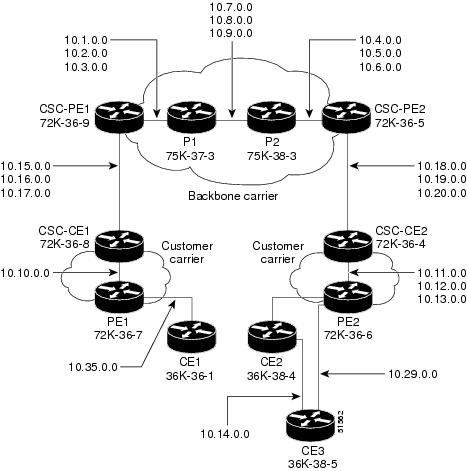
- Backbone Carrier Configuration
- Customer Carrier Site 1 Configuration
- Customer Carrier Site 2 Configuration
Backbone Carrier Configuration
- CSC-PE1 (72K-36-9) Configuration
- P1 (75K-37-3) Configuration
- P2 (75K-38-3) Configuration
- CSC-PE2 (72K-36-5) Configuration
CSC-PE1 (72K-36-9) Configuration
ip cef
!
ip vrf vpn1
rd 100:0
route-target export 100:0
route-target import 100:0
mpls label protocol ldp
!
!
interface Loopback0
ip address 10.14.14.14 255.255.255.255
no ip directed-broadcast
no ip route-cache
no ip mroute-cache
!
interface Loopback100
ip vrf forwarding vpn1
ip address 10.22.22.22 255.255.255.255
no ip directed-broadcast
!
interface ATM1/0
no ip address
no ip directed-broadcast
no ip mroute-cache
atm clock INTERNAL
no atm enable-ilmi-trap
no atm ilmi-keepalive
!
interface ATM1/0.1 point-to-point
ip address 10.1.0.1 255.255.0.0
no ip directed-broadcast
atm pvc 100 0 50 aal5snap
no atm enable-ilmi-trap
mpls label protocol ldp
tag-switching ip
!
interface ATM1/0.2 point-to-point
ip address 10.2.0.1 255.255.0.0
no ip directed-broadcast
atm pvc 101 0 51 aal5snap
no atm enable-ilmi-trap
mpls label protocol ldp
tag-switching ip
!
interface ATM1/0.3 point-to-point
ip address 10.3.0.1 255.255.0.0
no ip directed-broadcast
atm pvc 102 0 52 aal5snap
no atm enable-ilmi-trap
mpls label protocol ldp
tag-switching ip
!
interface ATM2/0
no ip address
no ip directed-broadcast
no ip mroute-cache
atm clock INTERNAL
no atm enable-ilmi-trap
no atm ilmi-keepalive
!
interface ATM2/0.1 point-to-point
ip vrf forwarding vpn1
ip address 10.15.0.2 255.255.0.0
no ip directed-broadcast
atm pvc 100 0 50 aal5snap
no atm enable-ilmi-trap
mpls label protocol ldp
tag-switching ip
!
interface ATM2/0.2 point-to-point
ip vrf forwarding vpn1
ip address 10.16.0.2 255.255.0.0
no ip directed-broadcast
atm pvc 101 0 51 aal5snap
no atm enable-ilmi-trap
mpls label protocol ldp
tag-switching ip
!
interface ATM2/0.3 point-to-point
ip vrf forwarding vpn1
ip address 10.17.0.2 255.255.0.0
no ip directed-broadcast
atm pvc 102 0 52 aal5snap
no atm enable-ilmi-trap
mpls label protocol ldp
tag-switching ip
!
router ospf 100
log-adjacency-changes
redistribute connected subnets
passive-interface ATM2/0.1
passive-interface ATM2/0.2
passive-interface ATM2/0.3
passive-interface Loopback100
network 10.14.14.14 0.0.0.0 area 100
network 10.1.0.0 0.0.255.255 area 100
network 10.2.0.0 0.0.255.255 area 100
network 10.3.0.0 0.0.255.255 area 100
!
router ospf 200 vrf vpn1
log-adjacency-changes
redistribute connected subnets
redistribute bgp 100 metric-type 1 subnets
network 10.22.22.22 0.0.0.0 area 200
network 10.15.0.0 0.0.255.255 area 200
network 10.16.0.0 0.0.255.255 area 200
network 10.17.0.0 0.0.255.255 area 200
!
router bgp 100
bgp log-neighbor-changes
timers bgp 10 30
neighbor 10.11.11.11 remote-as 100
neighbor 10.11.11.11 update-source Loopback0
!
address-family ipv4
neighbor 10.11.11.11 activate
neighbor 10.11.11.11 send-community extended
no synchronization
exit-address-family
!
address-family vpnv4
neighbor 10.11.11.11 activate
neighbor 10.11.11.11 send-community extended
exit-address-family
!
address-family ipv4 vrf vpn1
redistribute ospf 200 match internal external 1 external 2
no auto-summary
no synchronization
exit-address-family
P1 (75K-37-3) Configuration
ip cef distributed
!
mpls label protocol ldp
!
interface Loopback0
ip address 10.12.12.12 255.255.255.255
no ip directed-broadcast
no ip route-cache
no ip mroute-cache
!
interface ATM1/1/0
no ip address
no ip directed-broadcast
ip route-cache distributed
atm clock INTERNAL
no atm enable-ilmi-trap
no atm ilmi-keepalive
!
interface ATM1/1/0.1 point-to-point
ip address 10.7.0.1 255.255.0.0
no ip directed-broadcast
atm pvc 103 0 53 aal5snap
no atm enable-ilmi-trap
mpls label protocol ldp
tag-switching ip
!
interface ATM1/1/0.2 point-to-point
ip address 10.8.0.1 255.255.0.0
no ip directed-broadcast
atm pvc 104 0 54 aal5snap
no atm enable-ilmi-trap
mpls label protocol ldp
tag-switching ip
!
interface ATM1/1/0.3 point-to-point
ip address 10.9.0.1 255.255.0.0
no ip directed-broadcast
atm pvc 105 0 55 aal5snap
no atm enable-ilmi-trap
mpls label protocol ldp
tag-switching ip
!
interface ATM3/0/0
no ip address
no ip directed-broadcast
ip route-cache distributed
atm clock INTERNAL
atm sonet stm-1
no atm enable-ilmi-trap
no atm ilmi-keepalive
!
interface ATM3/0/0.1 point-to-point
ip address 10.1.0.2 255.255.0.0
no ip directed-broadcast
atm pvc 100 0 50 aal5snap
no atm enable-ilmi-trap
mpls label protocol ldp
mpls accounting experimental input
tag-switching ip
!
interface ATM3/0/0.2 point-to-point
ip address 10.2.0.2 255.255.0.0
no ip directed-broadcast
atm pvc 101 0 51 aal5snap
no atm enable-ilmi-trap
mpls label protocol ldp
tag-switching ip
!
interface ATM3/0/0.3 point-to-point
ip address 10.3.0.2 255.255.0.0
no ip directed-broadcast
atm pvc 102 0 52 aal5snap
no atm enable-ilmi-trap
mpls label protocol ldp
tag-switching ip
!
router ospf 100
log-adjacency-changes
redistribute connected subnets
network 10.12.12.12 0.0.0.0 area 100
network 10.1.0.0 0.0.255.255 area 100
network 10.2.0.0 0.0.255.255 area 100
network 10.3.0.0 0.0.255.255 area 100
network 10.7.0.0 0.0.255.255 area 100
network 10.8.0.0 0.0.255.255 area 100
network 10.9.0.0 0.0.255.255 area 100
P2 (75K-38-3) Configuration
ip cef distributed
!
mpls label protocol ldp
!
interface Loopback0
ip address 10.13.13.13 255.255.255.255
no ip directed-broadcast
no ip route-cache
no ip mroute-cache
!
interface ATM0/1/0
no ip address
no ip directed-broadcast
ip route-cache distributed
atm clock INTERNAL
atm sonet stm-1
no atm enable-ilmi-trap
no atm ilmi-keepalive
!
interface ATM0/1/0.1 point-to-point
ip address 10.7.0.2 255.255.0.0
no ip directed-broadcast
atm pvc 103 0 53 aal5snap
no atm enable-ilmi-trap
mpls label protocol ldp
tag-switching ip
!
interface ATM0/1/0.2 point-to-point
ip address 10.8.0.2 255.255.0.0
no ip directed-broadcast
atm pvc 104 0 54 aal5snap
no atm enable-ilmi-trap
mpls label protocol ldp
tag-switching ip
!
interface ATM0/1/0.3 point-to-point
ip address 10.9.0.2 255.255.0.0
no ip directed-broadcast
atm pvc 105 0 55 aal5snap
no atm enable-ilmi-trap
mpls label protocol ldp
tag-switching ip
!
interface ATM3/1/0
no ip address
no ip directed-broadcast
ip route-cache distributed
atm clock INTERNAL
atm sonet stm-1
no atm enable-ilmi-trap
no atm ilmi-keepalive
!
interface ATM3/1/0.1 point-to-point
ip address 10.4.0.2 255.255.0.0
no ip directed-broadcast
atm pvc 100 0 50 aal5snap
no atm enable-ilmi-trap
mpls label protocol ldp
tag-switching ip
!
interface ATM3/1/0.2 point-to-point
ip address 10.5.0.2 255.255.0.0
no ip directed-broadcast
atm pvc 101 0 51 aal5snap
no atm enable-ilmi-trap
mpls label protocol ldp
tag-switching ip
!
interface ATM3/1/0.3 point-to-point
ip address 10.6.0.2 255.255.0.0
no ip directed-broadcast
atm pvc 102 0 52 aal5snap
no atm enable-ilmi-trap
mpls label protocol ldp
tag-switching ip
!
router ospf 100
log-adjacency-changes
redistribute connected subnets
network 10.13.13.13 0.0.0.0 area 100
network 10.4.0.0 0.0.255.255 area 100
network 10.5.0.0 0.0.255.255 area 100
network 10.6.0.0 0.0.255.255 area 100
network 10.7.0.0 0.0.255.255 area 100
network 10.8.0.0 0.0.255.255 area 100
network 10.9.0.0 0.0.255.255 area 100
!
CSC-PE2 (72K-36-5) Configuration
ip cef
!
ip vrf vpn1
rd 100:0
route-target export 100:0
route-target import 100:0
mpls label protocol ldp
!
interface Loopback0
ip address 10.11.11.11 255.255.255.255
no ip directed-broadcast
no ip route-cache
no ip mroute-cache
!
interface Loopback100
ip vrf forwarding vpn1
ip address 10.23.23.23 255.255.255.255
no ip directed-broadcast
!
interface ATM5/0
no ip address
no ip directed-broadcast
no ip mroute-cache
atm clock INTERNAL
atm sonet stm-1
no atm enable-ilmi-trap
no atm ilmi-keepalive
!
interface ATM5/0.1 point-to-point
ip vrf forwarding vpn1
ip address 10.18.0.2 255.255.0.0
no ip directed-broadcast
atm pvc 100 0 50 aal5snap
no atm enable-ilmi-trap
mpls label protocol ldp
tag-switching ip
!
interface ATM5/0.2 point-to-point
ip vrf forwarding vpn1
ip address 10.19.0.2 255.255.0.0
no ip directed-broadcast
atm pvc 101 0 51 aal5snap
no atm enable-ilmi-trap
mpls label protocol ldp
tag-switching ip
!
interface ATM5/0.3 point-to-point
ip vrf forwarding vpn1
ip address 10.20.0.2 255.255.0.0
no ip directed-broadcast
atm pvc 102 0 52 aal5snap
no atm enable-ilmi-trap
mpls label protocol ldp
tag-switching ip
!
interface ATM6/0
no ip address
no ip directed-broadcast
no ip mroute-cache
atm clock INTERNAL
atm sonet stm-1
no atm enable-ilmi-trap
no atm ilmi-keepalive
!
interface ATM6/0.1 point-to-point
ip address 10.4.0.1 255.255.0.0
no ip directed-broadcast
atm pvc 100 0 50 aal5snap
no atm enable-ilmi-trap
mpls label protocol ldp
tag-switching ip
!
interface ATM6/0.2 point-to-point
ip address 10.5.0.1 255.255.0.0
no ip directed-broadcast
atm pvc 101 0 51 aal5snap
no atm enable-ilmi-trap
mpls label protocol ldp
tag-switching ip
!
interface ATM6/0.3 point-to-point
ip address 10.6.0.1 255.255.0.0
no ip directed-broadcast
atm pvc 102 0 52 aal5snap
no atm enable-ilmi-trap
mpls label protocol ldp
tag-switching ip
!
router ospf 100
log-adjacency-changes
redistribute connected subnets
passive-interface ATM5/0.1
passive-interface ATM5/0.2
passive-interface ATM5/0.3
passive-interface Loopback100
network 10.11.11.11 0.0.0.0 area 100
network 10.4.0.0 0.0.255.255 area 100
network 10.5.0.0 0.0.255.255 area 100
network 10.6.0.0 0.0.255.255 area 100
!
router ospf 200 vrf vpn1
log-adjacency-changes
redistribute connected subnets
redistribute bgp 100 metric-type 1 subnets
network 10.23.23.23 0.0.0.0 area 200
network 10.18.0.0 0.0.255.255 area 200
network 10.19.0.0 0.0.255.255 area 200
network 10.20.0.0 0.0.255.255 area 200
!
router bgp 100
bgp log-neighbor-changes
timers bgp 10 30
neighbor 10.14.14.14 remote-as 100
neighbor 10.14.14.14 update-source Loopback0
!
address-family ipv4
neighbor 10.14.14.14 activate
neighbor 10.14.14.14 send-community extended
no synchronization
exit-address-family
!
address-family vpnv4
neighbor 10.14.14.14 activate
neighbor 10.14.14.14 send-community extended
exit-address-family
!
address-family ipv4 vrf vpn1
redistribute ospf 200 match internal external 1 external 2
no auto-summary
no synchronization
exit-address-family
Customer Carrier Site 1 Configuration
CSC-CE1 (72K-36-8) Configuration
ip cef
!
mpls label protocol ldp
!
interface Loopback0
ip address 10.15.15.15 255.255.255.255
no ip directed-broadcast
no ip route-cache
no ip mroute-cache
!
interface ATM1/0
no ip address
no ip directed-broadcast
no ip mroute-cache
atm clock INTERNAL
atm sonet stm-1
no atm enable-ilmi-trap
no atm ilmi-keepalive
!
interface ATM1/0.1 point-to-point
ip address 10.15.0.1 255.255.0.0
no ip directed-broadcast
atm pvc 100 0 50 aal5snap
no atm enable-ilmi-trap
mpls label protocol ldp
tag-switching ip
!
interface ATM1/0.2 point-to-point
ip address 10.16.0.1 255.255.0.0
no ip directed-broadcast
atm pvc 101 0 51 aal5snap
no atm enable-ilmi-trap
mpls label protocol ldp
tag-switching ip
!
interface ATM1/0.3 point-to-point
ip address 10.17.0.1 255.255.0.0
no ip directed-broadcast
atm pvc 102 0 52 aal5snap
no atm enable-ilmi-trap
mpls label protocol ldp
tag-switching ip
!
interface Ethernet3/1
ip address 10.10.0.2 255.255.0.0
no ip directed-broadcast
no ip mroute-cache
mpls label protocol ldp
tag-switching ip
!
router ospf 200
log-adjacency-changes
redistribute connected subnets
network 10.15.15.15 0.0.0.0 area 200
network 10.10.0.0 0.0.255.255 area 200
network 10.15.0.0 0.0.255.255 area 200
network 10.16.0.0 0.0.255.255 area 200
network 10.17.0.0 0.0.255.255 area 200
PE2 (72K-36-7) Configuration
ip cef
!
ip vrf vpn2
 rd 200:1
 route-target export 200:1
 route-target import 200:1
no mpls ip propagate-ttl
!
interface Loopback0
 ip address 10.24.24.24 255.255.255.255
 no ip directed-broadcast
 no ip route-cache
 no ip mroute-cache
!
interface Ethernet3/0
 ip address 10.0.0.1 255.0.0.0
 no ip directed-broadcast
 no ip mroute-cache
mpls label protocol ldp
mpls ip
!
interface Ethernet3/1
 ip vrf forwarding vpn2
 ip address 10.0.0.1 255.0.0.0
 no ip directed-broadcast
 no ip mroute-cache
!
interface Ethernet3/2
 ip address 10.0.0.2 255.0.0.0
 no ip directed-broadcast
 no ip mroute-cache
mpls label protocol ldp
mpls ip
!
interface Ethernet3/3
 ip address 10.0.0.2 255.0.0.0
 no ip directed-broadcast
 no ip mroute-cache
mpls label protocol ldp
mpls ip
!
router ospf 1
 network 10.0.0.0 0.255.255.255 area 101
 network 10.0.0.0 0.255.255.255 area 101
 network 10.0.0.0 0.255.255.255 area 101
 network 10.0.0.0 0.255.255.255 area 101
!
router bgp 200
 neighbor 10.22.22.22 remote-as 200
 neighbor 10.22.22.22 update-source Loopback0
 neighbor 10.23.23.23 remote-as 200
 neighbor 10.23.23.23 update-source Loopback0
 !
 address-family ipv4 vrf vpn2
 neighbor 10.0.0.2 remote-as 300
 neighbor 10.0.0.2 activate
 neighbor 10.0.0.2 as-override
 no auto-summary
 no synchronization
 exit-address-family
 !
 address-family vpnv4
 neighbor 10.22.22.22 activate
 neighbor 10.22.22.22 send-community extended
 neighbor 10.23.23.23 activate
 neighbor 10.23.23.23 send-community extended
 exit-address-family
CE1 (36K-36-1) Configuration
ip cef
!
interface Loopback0
ip address 10.19.19.19 255.255.255.255
no ip directed-broadcast
!
interface Ethernet0/2
ip address 30.35.0.1 255.255.0.0
no ip directed-broadcast
!
router ospf 300
log-adjacency-changes
redistribute connected subnets
redistribute bgp 300 subnets
passive-interface Ethernet0/2
network 10.19.19.19 0.0.0.0 area 300
!
router bgp 300
no synchronization
bgp log-neighbor-changes
timers bgp 10 30
redistribute connected
redistribute ospf 300 match internal external 1 external 2
neighbor 10.35.0.2 remote-as 200
neighbor 10.35.0.2 advertisement-interval 5
no auto-summary
Customer Carrier Site 2 Configuration
- CSC-CE2 (72K-36-4) Configuration
- PE2 (72K-36-6) Configuration
- CE2 (36K-38-4) Configuration
- CE3 (36K-38-5) Configuration
CSC-CE2 (72K-36-4) Configuration
ip cef
!
mpls label protocol ldp
!
interface Loopback0
ip address 10.17.17.17 255.255.255.255
no ip directed-broadcast
!
interface ATM5/0
no ip address
no ip directed-broadcast
atm clock INTERNAL
atm sonet stm-1
no atm enable-ilmi-trap
no atm ilmi-keepalive
!
interface ATM5/0.1 point-to-point
ip address 10.11.0.2 255.255.0.0
no ip directed-broadcast
atm pvc 100 0 50 aal5snap
no atm enable-ilmi-trap
mpls label protocol ldp
tag-switching ip
!
interface ATM5/0.2 point-to-point
ip address 10.12.0.2 255.255.0.0
no ip directed-broadcast
atm pvc 101 0 51 aal5snap
no atm enable-ilmi-trap
mpls label protocol ldp
tag-switching ip
!
interface ATM5/0.3 point-to-point
ip address 10.13.0.2 255.255.0.0
no ip directed-broadcast
atm pvc 102 0 52 aal5snap
no atm enable-ilmi-trap
mpls label protocol ldp
tag-switching ip
!
interface ATM6/0
no ip address
no ip directed-broadcast
atm clock INTERNAL
atm sonet stm-1
no atm enable-ilmi-trap
no atm ilmi-keepalive
!
interface ATM6/0.1 point-to-point
ip address 10.18.0.1 255.255.0.0
no ip directed-broadcast
atm pvc 100 0 50 aal5snap
no atm enable-ilmi-trap
mpls label protocol ldp
tag-switching ip
!
interface ATM6/0.2 point-to-point
ip address 10.19.0.1 255.255.0.0
no ip directed-broadcast
atm pvc 101 0 51 aal5snap
no atm enable-ilmi-trap
mpls label protocol ldp
tag-switching ip
!
interface ATM6/0.3 point-to-point
ip address 10.20.0.1 255.255.0.0
no ip directed-broadcast
atm pvc 102 0 52 aal5snap
no atm enable-ilmi-trap
mpls label protocol ldp
tag-switching ip
!
router ospf 200
log-adjacency-changes
redistribute connected subnets
network 10.17.17.17 0.0.0.0 area 200
network 10.11.0.0 0.0.255.255 area 200
network 10.12.0.0 0.0.255.255 area 200
network 10.13.0.0 0.0.255.255 area 200
network 10.18.0.0 0.0.255.255 area 200
network 10.19.0.0 0.0.255.255 area 200
network 10.20.0.0 0.0.255.255 area 200
PE2 (72K-36-6) Configuration
ip cef
!
ip vrf customersite
rd 200:1
route-target export 200:1
route-target import 200:1
mpls label protocol ldp
!
interface Loopback0
ip address 10.18.18.18 255.255.255.255
no ip directed-broadcast
no ip route-cache
no ip mroute-cache
!
interface Ethernet3/0
ip vrf forwarding customersite
ip address 10.29.0.2 255.255.0.0
no ip directed-broadcast
!
interface Ethernet3/1
ip vrf forwarding customersite
ip address 10.30.0.2 255.255.0.0
no ip directed-broadcast
!
interface ATM5/0
no ip address
no ip directed-broadcast
no ip mroute-cache
atm clock INTERNAL
atm sonet stm-1
no atm enable-ilmi-trap
no atm ilmi-keepalive
!
interface ATM5/0.1 point-to-point
ip address 10.11.0.1 255.255.0.0
no ip directed-broadcast
atm pvc 100 0 50 aal5snap
no atm enable-ilmi-trap
mpls label protocol ldp
tag-switching ip
!
interface ATM5/0.2 point-to-point
ip address 10.12.0.1 255.255.0.0
no ip directed-broadcast
atm pvc 101 0 51 aal5snap
no atm enable-ilmi-trap
mpls label protocol ldp
tag-switching ip
!
interface ATM5/0.3 point-to-point
ip address 10.13.0.1 255.255.0.0
no ip directed-broadcast
atm pvc 102 0 52 aal5snap
no atm enable-ilmi-trap
mpls label protocol ldp
tag-switching ip
!
router ospf 200
log-adjacency-changes
redistribute connected subnets
passive-interface Ethernet3/0
passive-interface Ethernet3/1
network 10.18.18.18 0.0.0.0 area 200
network 10.11.0.0 0.0.255.255 area 200
network 10.12.0.0 0.0.255.255 area 200
network 10.13.0.0 0.0.255.255 area 200
!
router bgp 200
no bgp default ipv4-unicast
bgp log-neighbor-changes
timers bgp 10 30
neighbor 10.16.16.16 remote-as 200
neighbor 10.16.16.16 update-source Loopback0
!
address-family ipv4
neighbor 10.16.16.16 activate
neighbor 10.16.16.16 send-community extended
no synchronization
exit-address-family
!
address-family vpnv4
neighbor 10.16.16.16 activate
neighbor 10.16.16.16 send-community extended
exit-address-family
!
address-family ipv4 vrf customersite
neighbor 10.29.0.1 remote-as 300
neighbor 10.29.0.1 activate
neighbor 10.29.0.1 as-override
neighbor 10.29.0.1 advertisement-interval 5
neighbor 10.30.0.1 remote-as 300
neighbor 10.30.0.1 activate
neighbor 10.30.0.1 as-override
neighbor 10.30.0.1 advertisement-interval 5
no auto-summary
no synchronization
exit-address-family
CE2 (36K-38-4) Configuration
ip cef
!
interface Loopback0
ip address 10.21.21.21 255.255.255.255
!
interface Ethernet1/3
ip address 10.29.0.1 255.255.0.0
!
interface Ethernet5/0
ip address 10.14.0.1 255.255.0.0
!
router ospf 300
log-adjacency-changes
redistribute connected subnets
redistribute bgp 300 subnets
passive-interface Ethernet1/3
network 10.21.21.21 0.0.0.0 area 300
network 10.14.0.0 0.0.255.255 area 300
!
router bgp 300
no synchronization
timers bgp 10 30
redistribute connected
redistribute ospf 300 match internal external 1 external 2
neighbor 10.29.0.2 remote-as 200
neighbor 10.29.0.2 advertisement-interval 5
no auto-summary
CE3 (36K-38-5) Configuration
ip cef
!
interface Loopback0
ip address 10.20.20.20 255.255.255.255
no ip directed-broadcast
!
interface Ethernet0/2
ip address 10.30.0.1 255.255.0.0
no ip directed-broadcast
!
interface Ethernet0/3
ip address 10.14.0.2 255.255.0.0
no ip directed-broadcast
!
router ospf 300
log-adjacency-changes
redistribute connected subnets
redistribute bgp 300 subnets
passive-interface Ethernet0/2
network 10.20.20.20 0.0.0.0 area 300
network 10.14.0.0 0.0.255.255 area 300
!
router bgp 300
no synchronization
bgp log-neighbor-changes
timers bgp 10 30
redistribute connected
redistribute ospf 300 match internal external 1 external 2
neighbor 10.30.0.2 remote-as 200
neighbor 10.30.0.2 advertisement-interval 5
no auto-summary
Additional References for MPLS VPN Carrier Supporting Carrier Using LDP and an IGP
Related Documents
|
Related Topic |
Document Title |
|---|---|
|
MPLS |
RFCs
|
RFC |
Title |
|---|---|
|
RFC 2547 |
BGP/MPLS VPNs |
Technical Assistance
|
Description |
Link |
|---|---|
|
The Cisco Support and Documentation website provides online resources to download documentation, software, and tools. Use these resources to install and configure the software and to troubleshoot and resolve technical issues with Cisco products and technologies. Access to most tools on the Cisco Support and Documentation website requires a Cisco.com user ID and password |
Feature Information for MPLS VPN CSC with LDP and IGP
The following table provides release information about the feature or features described in this module. This table lists only the software release that introduced support for a given feature in a given software release train. Unless noted otherwise, subsequent releases of that software release train also support that feature.
Use Cisco Feature Navigator to find information about platform support and Cisco software image support. To access Cisco Feature Navigator, go to www.cisco.com/go/cfn. An account on Cisco.com is not required.
|
Feature Name |
Releases |
Feature Configuration Information |
|---|---|---|
|
MPLS VPN Carrier Supporting Carrier |
12.0(14)ST 12.0(16)ST 12.2(8)T 12.0(21)ST 12.0(22)S 12.0(23)S Cisco IOS XE Release 2.2 |
This feature enables you to set up and create an MPLS VPN CSC network that uses LDP to transport MPLS labels and an IGP to transport routes. In 12.0(14)ST, this feature was introduced. In 12.0(16)ST, this feature was integrated. In 12.2(8)T, this feature was integrated. In 12.0(21)ST, this feature was integrated. In 12.0(22)S, this feature was integrated. In 12.0(23)S, this feature was integrated. In Cisco IOS XE Release 2.2, this feature was implemented on the Cisco ASR 1000 Series Routers. This feature uses no new or modified commands. |
Glossary
ASBR -- Autonomous System Boundary router. A router that connects one autonomous system to another.
autonomous system --A collection of networks under a common administration sharing a common routing strategy.
BGP --Border Gateway Protocol. An interdomain routing protocol that exchanges network reachability information with other BGP systems (which may be within the same autonomous system or between multiple autonomous systems).
CE router--customer edge router. A router that is part of a customer network and that interfaces to a provider edge (PE) router. CE routers do not recognize associated MPLS VPNs.
CSC --Carrier Supporting Carrier. A hierarchical VPN model that allows small service providers, or customer carriers, to interconnect their IP or MPLS networks over an MPLS backbone. This eliminates the need for customer carriers to build and maintain their own MPLS backbone.
eBGP --external Border Gateway Protocol. A BGP between routers located within different autonomous systems. When two routers, located in different autonomous systems, are more than one hop away from one another, the eBGP session between the two routers is considered a multihop BGP.
edge router--A router that is at the edge of the network. It defines the boundary of the MPLS network. It receives and transmits packets. Also referred to as edge label switch router and label edge router.
iBGP --internal Border Gateway Protocol. A BGP between routers within the same autonomous system.
IGP --Interior Gateway Protocol. Internet protocol used to exchange routing information within a single autonomous system. Examples of common Internet IGP protocols include IGRP, OSPF, IS-IS, and RIP.
IP --Internet Protocol. Network layer protocol in the TCP/IP stack offering a connectionless internetwork service. IP provides features for addressing, type-of-service specification, fragmentation and reassembly, and security. Defined in RFC 791.
LDP --Label Distribution Protocol. A standard protocol between MPLS-enabled routers to negotiate the labels (addresses) used to forward packets.
LFIB --Label Forwarding Information Base. Data structure used in MPLS to hold information about incoming and outgoing labels and associated Forwarding Equivalence Class (FEC) packets.
MP-BGP --Multiprotocol BGP.
MPLS --Multiprotocol Label Switching. The name of the IETF working group responsible for label switching, and the name of the label switching approach it has standardized.
NLRI --Network Layer Reachability Information. The BGP sends routing update messages containing NLRI to describe a route and how to get there. In this context, an NLRI is a prefix. A BGP update message carries one or more NLRI prefixes and the attributes of a route for the NLRI prefixes; the route attributes include a BGP next hop gateway address and extended community values.
NSF --Nonstop forwarding enables routers to continuously forward IP packets following a Route Processor takeover or switchover to another Route Processor. NSF maintains and updates Layer 3 routing and forwarding information in the backup Route Processor to ensure that IP packets and routing protocol information are forwarded continuously during the switchover and route convergence process.
PE router--provider edge router. A router that is part of a service provider’s network. It is connected to a customer edge (CE) router. All MPLS VPN processing occurs in the PE router.
QoS --quality of service. Measure of performance for a transmission system that indicates its transmission quality and service availability.
RD --route distinguisher. An 8-byte value that is concatenated with an IPv4 prefix to create a unique VPN-IPv4 prefix.
RT --route target. Extended community attribute used to identify the VRF routing table into which a prefix is imported.
SLA --Service Level Agreement given to VPN subscribers.
VPN --Virtual Private Network. A secure MPLS-based network that shares resources on one or more physical networks (typically implemented by one or more service providers). A VPN contains geographically dispersed sites that can communicate securely over a shared backbone network.
VRF --VPN routing and forwarding instance. Routing information that defines a VPN site that is attached to a PE router. A VRF consists of an IP routing table, a derived forwarding table, a set of interfaces that use the forwarding table, and a set of rules and routing protocols that determine what goes into the forwarding table.