- Restrictions for AAL5 L3 Termination
- Information About AAL5 L3 Termination
- How to Configure AAL5 L3 Termination
- Configuration Examples for AAL5 L3 Termination
- Example: Configuring SONET mode on OC-3 IM
- Example: Configuring SDH mode on OC-3 IM
- Example: Configuring SONET mode on OC-12 IM
- Example: Configuring SDH mode on OC-12 IM
- Example: Configuring Layer2 QoS
- Example: Configuring Protocol IP Broadcast in the Layer3 ATM Interface
- Example: Configuring VRF Enabled ATM L3 Interface
- Verifying AAL5 L3 Termination
- Additional References
Configuring AAL5 L3 Termination
This feature enables the Asynchronous Transfer Mode Adaptation Layer 5 (AAL5) layer 3 termination on the interface module (IM) (T1/E1 and OC-3) cards on the Cisco ASR 903 Router.
- Restrictions for AAL5 L3 Termination
- Information About AAL5 L3 Termination
- How to Configure AAL5 L3 Termination
- Configuration Examples for AAL5 L3 Termination
- Verifying AAL5 L3 Termination
- Additional References
Restrictions for AAL5 L3 Termination
- Main interface cannot be configured as layer 3 Asynchronous Transfer Mode (ATM) interface. Therefore you cannot create layer 3 Permanent Virtual Circuits (PVC) under main interface.
- Point-to-multipoint sub-interface is not supported.
- Quadrature Amplitude Modulation (QAM) is not supported on ATM L3 Interface.
- Operations, administration, and maintenance (OAM) is not supported on ATM L3 interface.
- You cannot swap from layer 2 transport ATM to layer 3 ATM interface without deleting ATM sub-interface.
- ATM layer 3 Permanent Virtual Path (PVP) is not supported.
- Inverse Multiplexing for ATM is not supported.
- ATM adaptation layer 5 Subnetwork Access Protocol SNAP (AAL5SNAP) protocol is supported. AAL0 is not supported.
- ATM L3 QoS is not supported.
- One port of an interface module (IM) supports only one interface configuration. For example, one OC-3 port can support one of the following configurations and not a combination of configurations: Different interface configurations can be configured on different ports of the same IM.
Information About AAL5 L3 Termination
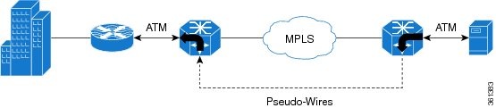
When ATM feature is enabled, IMs can be deployed for ATM service that delivers high-performance interconnectivity, metro, and intra-point of presence (POP) applications between service POPs for IP/Multiprotocol Label Switching (IP/MPLS) transport (Figure 1).
AAL5 L3 termination can also be deployed at customer premises equipment (CPE) to provide the data component for the service provider networks. The ATM service allows service providers to effectively manage the bandwidth at the edges of the network while implementing value-added Layer 3 service.
Scale Supported for AAL5 L3 Termination
How to Configure AAL5 L3 Termination
Configuring Layer 3 Terminated VCs
PVCs configured on the router remain active until the circuit is removed from the configuration. All virtual circuit characteristics apply to PVCs. When a PVC is configured, all configuration options are passed to the TDM IMs. These PVCs are written to the nonvolatile RAM (NVRAM) as part of the configuration and are used when the Cisco IOS image is reloaded.
When you create a PVC, you create a virtual circuit descriptor (VCD) and attach it to the VPI and VCI. The VCD tells the card which VPI/VCI to use for a particular packet. The TDM IM card requires this feature to manage the packets for transmission. The number chosen for the VCD is independent of the virtual path identifier/virtual channel identifier (VPI/VCI) used.
1.
enable
2.
configure
terminal
3. controller {t1 | e1} slot/bay/port
4.
atm
5.
interface
atm
interface-number [.subinterface-number
point-to-point]
6.
ip
address
ip-addressip-address-mask
7.
pvc
[name]
vpi|vci
8.
encapsulation
aal5snap
9.
end
DETAILED STEPS
Configuring Layer2 QoS on the ATM Interface
1.
enable
2.
configure
terminal
3. controller {t1 | e1slot/bay/port}
4.
atm
5.
interfaceinterface-number
atm
[.subinterface-number
point-to-point]
6.
ip
address
ip-address
ip-address-mask
7.
no
atm
enable-ilmi-trap
8.
pvc
[name]
vpi|vci
9.
Do one of the
following:
10.
encapsulation
aal5snap
11.
end
DETAILED STEPS
Configuring Protocol IP Broadcast on ATM L3 Interface
1.
enable
2.
configure
terminal
3. controller {t1 | e1} slot/bay/port
4.
atm
5.
interface
interface-number
atm
[.subinterface-number
point-to-point]
6.
ip
addressip-address
ip-address-mask
7.
no
atm
enable-ilmi-trap
8.
pvc
[name]
vpi|vci
9.
protocol ip
protocol-address
[no]
broadcast
10.
encapsulation
aal5snap
11.
end
DETAILED STEPS
Configuring VRF Enabled ATM L3 Interface
1.
enable
2.
configure
terminal
3. controller {t1 | e1} slot/bay/port
4.
atm
5.
interface
interface-numberatm
[.subinterface-number
point-to-point]
6. ip vrf forwarding vrf-name [downstream vrf-name2 ]
7.
ip
addressip-address
ip-address-mask
8.
no
atm
enable-ilmi-trap
9.
pvc
[name]vpi
|vci
10.
encapsulation
aal5snap
11.
end
DETAILED STEPS
Configuration Examples for AAL5 L3 Termination
Example: Configuring SONET mode on OC-3 IM
Router(config)# controller sonet 3/1/0
Router(config-controller)# framing sonet
Router(config-controller)# sts-1 1
Router(config-ctrlr-sts)# vtg 1 t1 1 atm
Router(config)# interface ATM3/1/0.1/1/1.1 point-to-point
Router(config-subif)# ip address 192.0.1.5 255.255.255.0
Router(config-subif)# pvc 10/100
Router(cfg-if-atm-vc)# encapsulation aal5snap
Router(cfg-if-atm-vc)#
Example: Configuring SDH mode on OC-3 IM
Router(config)# controller sonet 0/1/0
Router(config-controller)# framing sdh
Router(config-controller)# aug mapping au-4
Router(config-controller)# au-4 1 tug-3 1
Router(config-ctrlr-tug3)# tug-2 1 e1 1 atm
Router(config)# interface ATM0/0/0.1/1/1/1.2 point-to-point
Router(config-subif)# ip address 192.0.2.3 255.255.255.0
Router(config-subif)# pvc 10/100
Router(cfg-if-atm-vc)# encapsulation aal5snap
Router(cfg-if-atm-vc)#
Example: Configuring SONET mode on OC-12 IM
Router(config)# controller sonet 0/1/0
Router(config-controller)# framing sonet
Router(config-controller)# sts-1 1
Router(config-ctrlr-sts)# vtg 1 t1 1 atm
Router(config)# interface ATM3/1/0.1/1/1.1 point-to-point
Router(config-subif)# ip address 192.0.1.5 255.255.255.0
Router(config-subif)# pvc 10/100
Router(cfg-if-atm-vc)# encapsulation aal5snap
Router(cfg-if-atm-vc)#
Example: Configuring SDH mode on OC-12 IM
Router(config)# controller sonet 0/1/0
Router(config-controller)# framing sdh
Router(config-controller)# aug mapping au-4
Router(config-controller)# au-4 1 tug-3 1
Router(config-ctrlr-tug3)# tug-2 1 e1 1 atm
Router(config)# interface ATM0/0/0.1/1/1/1.2 point-to-point
Router(config-subif)# ip address 192.0.2.3 255.255.255.0
Router(config-subif)# pvc 10/100
Router(cfg-if-atm-vc)# encapsulation aal5snap
Router(cfg-if-atm-vc)#
Example: Configuring Layer2 QoS
interface ATM0/3/2.1/1/1.101 point-to-point
no atm enable-ilmi-trap
pvc 20/101
  ubr 100
  encapsulation aal5snap
   !
End
interface ATM1/1/0.1/1/1.102 point-to-point
ip address 192.0.2.1 255.255.255.0
no atm enable-ilmi-trap
pvc 20/102
  cbr 1000
  encapsulation aal5snap
interface ATM1/1/0.1/1/1.102 point-to-point
ip address 192.0.2.1 255.255.255.0
no atm enable-ilmi-trap
pvc 20/102
  vbr-rt 1000 600 20
  encapsulation aal5snap
interface ATM1/1/0.1/1/1.102 point-to-point
ip address 192.0.2.1 255.255.255.0
no atm enable-ilmi-trap
pvc 20/102
  vbr-nrt 1500 1000 10
  encapsulation aal5snap
interface ATM1/1/0.1/1/1.102 point-to-point
ip address 192.0.2.1 255.255.255.0
no atm enable-ilmi-trap
pvc 20/102
  ubr+ 1000 100
  encapsulation aal5snap
Example: Configuring Protocol IP Broadcast in the Layer3 ATM Interface
interface ATM0/3/2.1/1/1.200 point-to-point
ip address 192.168.1.2 255.255.255.0
no atm enable-ilmi-trap
pvc 200/10
  protocol ip 192.168.1.2 broadcast ----------(remote end IP)
!
End
Example: Configuring VRF Enabled ATM L3 Interface
ip vrf VPN_A
rd 100:1
route-target export 100:1
route-target import 100:1
interface ATM0/3/2.1/1/1.200 point-to-point
ip vrf forwarding VPN_A
ip address 10.0.0.1 255.255.255.0
no atm enable-ilmi-trap
pvc 200/10
 !
End
Router# ping vrf VPN_A 11.12.13.14 -------(Remote end IP)
Type escape sequence to abort.
Sending 5, 100-byte ICMP Echos to 10.0.0.1, timeout is 2 seconds:
!!!!!
Verifying AAL5 L3 Termination
-
- Use the show atm pvc
command to display all ATM PVCs and traffic information:
Router# show atm pvc Keys: C = ATM0/4/0.1/1/1, B = ATM0/4/2.1/1/1, VCD / Peak Av/Min Burst Interface Name VPI VCI Type Encaps SC Kbps Kbps Cells St C.1 1 180 181 PVC SNAP UBR 1536 UP B.1 1 180 181 PVC AAL5 UBR 1536 UP -
Use the show interfaces ATM command to display information about the ATM interface: Router# show interfaces AT0/4/0.1/1/1.1 ATM0/4/0.1/1/1.1 is up, line protocol is up Hardware is A900-IMA4OS, address is 0022.bddd.d4c0 (bia 0022.bddd.d4c0) Internet address is 192.168.0.1/24 MTU 4470 bytes, BW 1536 Kbit/sec, DLY 100 usec, reliability 255/255, txload 129/255, rxload 129/255 Encapsulation ATM Keepalive not supported 13551261 packets input, 731768094 bytes 13551227 packets output, 731766258 bytes 0 OAM cells input, 0 OAM cells output AAL5 CRC errors : 0 AAL5 SAR Timeouts : 0 AAL5 Oversized SDUs : 0 AAL5 length violation : 0 Last clearing of "show interface" counters never -
Use the show atm pvc interface atm interface-number command to display all PVCs on the specified interface or sub-interface: Router# show atm pvc interface atm 0/4/0.1/1/1.1 Key: C = ATM0/4/0.1/1/1 VCD / Peak Av/Min Burst Interface Name VPI VCI Type Encaps SC Kbps Kbps Cells St C.1 1 180 181 PVC SNAP UBR 1536 UP -
Use the show atm map command to display the protocol IP broadcast on the ATM interface: Router# show atm map Map list ATM0/3/2.1/1/1.200pvcC8000A : PERMANENT ip 191.168.1.14 maps to VC 5, VPI 200, VCI 10, ATM0/3/2.1/1/1.200 , broadcast
- Use the show atm pvc
command to display all ATM PVCs and traffic information:
Additional References
Related Documents
|
Related Topic |
Document Title |
|---|---|
|
Cisco IOS commands |
|
|
ATM commands |
Cisco IOS Asynchronous Transfer Mode Command Reference |
MIBs
|
MIB |
MIBs Link |
|---|---|
|
To locate and download MIBs for selected platforms, Cisco software releases, and feature sets, use Cisco MIB Locator found at the following URL: |
 Feedback