- Configuring URL Hashing
- Configuring Firewall Load Balancing
Configuring Advanced Server Load Balancing
This chapter describes how to configure advanced server load balancing (SLB) on the CSM and contains these sections:
•![]() Configuring Firewall Load Balancing
Configuring Firewall Load Balancing
•![]() Configuring Generic Header Parsing
Configuring Generic Header Parsing
•![]() Configuring Persistent Connections
Configuring Persistent Connections
•![]() Configuring Connection Redundancy
Configuring Connection Redundancy
•![]() Configuring a Hitless Upgrade
Configuring a Hitless Upgrade
•![]() Configuring SNMP Traps for Real Servers
Configuring SNMP Traps for Real Servers
•![]() Configuring Global Server Load Balancing
Configuring Global Server Load Balancing
•![]() Configuring the XML Interface
Configuring the XML Interface
Configuring URL Hashing
When you choose a server farm for a connection, you can select a specific real server in that server farm. You can choose least connections, round robin, or URL hashing to select a real server.
URL hashing is a load-balancing predictor for Layer 7 connections. You can configure URL hashing on the CSM on a server farm-by-server farm basis. The CSM chooses the real server by using a hash value based on a URL. This hash value may be computed on the entire URL or on a portion of it. To select only a portion of the URL for hashing, you can specify the beginning and ending patterns in the URL so that only the portion of the URL from the specified beginning pattern through the specified ending pattern is hashed.
The CSM supports URL hashing in software release 2.1(1).
Configuring a URL Hashing Predictor
You configure the URL hashing predictor on a server farm-by-server farm basis. Unless you specify a beginning and an ending pattern (see the "Configuring Beginning and Ending Patterns" section), the entire URL is hashed and used to select a real server.
You must configure URL hashing for all server farms that will be using the URL hashing predictor, regardless of whether they are using the entire URL or a beginning and ending pattern.
To configure URL hashing as a load-balancing predictor for a server farm, perform this task:
|
|
|
|
|---|---|---|
Router(config-slb-sfarm)# predictor hash url |
Configures the URL hashing and load-balancing predictor for a server farm. |
This example shows how to configure URL hashing and load-balancing predictor for a server farm:
Router(config)# mod csm 2
Router(config-module-csm)# serverfarm farm1
Router(config-slb-sfarm)# predictor hash url
Router(config-slb-sfarm)# real 10.1.0.105
Router(config-slb-real)# inservice
Router(config-slb-real)# exit
Configuring Beginning and Ending Patterns
When you configure a beginning and ending pattern, you do so at the virtual server level. The pattern you define will apply to all the server farms assigned to all of the policies in that virtual server that have URL hashing enabled.
The beginning and ending pattern delimits the portion of the URL that will be hashed and used as a predictor to select a real server from a server farm that belongs to any policy assigned to that virtual server.
To hash a substring of the URL instead of the entire URL, specify the beginning and ending patterns in vserver vserver-name submode with the url-hash begin-pattern pattern-a command and url-hash end-pattern pattern-b command. Hashing occurs at the start of the beginning pattern and goes to the ending pattern.
For example, in the following URL, if the beginning pattern is c&k=, and the ending pattern is &, only the substring c&k=c is hashed:
http://quote.yahoo.com/q?s=csco&d=c&k=c1&t=2y&a=v&p=s&l=on&z=m&q=l\

Note ![]() Beginning and ending patterns are restricted to fixed constant strings. General regular expressions cannot be specified as patterns. If no beginning pattern is specified, hashing begins at the beginning of the URL. If no ending pattern is specified, hashing ends at the end of the URL.
Beginning and ending patterns are restricted to fixed constant strings. General regular expressions cannot be specified as patterns. If no beginning pattern is specified, hashing begins at the beginning of the URL. If no ending pattern is specified, hashing ends at the end of the URL.
This example shows how to configure beginning and ending patterns for URL hashing:
Router(config-module-csm)#
Router(config-module-csm)# vserver vs1
Router(config-slb-vserver)# virtual 10.1.0.81 tcp 80
Router(config-slb-vserver)# url-hash begin-pattern c&k= end-pattern &
Router(config-slb-vserver)# serverfarm farm1
Router(config-slb-vserver)# inservice
Router(config-slb-vserver)#
Router(config-slb-vserver)# exit
Router(config-module-csm)# exit
Configuring Firewall Load Balancing
Firewall load balancing allows you to scale firewall protection by distributing traffic across multiple firewalls on a per-connection basis. All packets belonging to a particular connection must go through the same firewall. The firewall then allows or denies transmission of individual packets across its interfaces.
This section describes how to configure firewall load balancing for regular and stealth firewalls. It covers the following topics:
•![]() Understanding How Firewalls Work
Understanding How Firewalls Work
•![]() Configuring Stealth Firewall Load Balancing
Configuring Stealth Firewall Load Balancing
•![]() Configuring Regular Firewall Load Balancing
Configuring Regular Firewall Load Balancing
•![]() Configuring Reverse-Sticky for Firewalls
Configuring Reverse-Sticky for Firewalls
Understanding How Firewalls Work
A firewall forms a physical barrier between two parts of a network: the Internet and an intranet, for example. When a firewall accepts a packet from one side (the Internet), it sends the packet through to the other side (the intranet). A firewall can modify a packet before passing it through or send it through unaltered. When a firewall rejects a packet, it usually drops the packet and logs the dropped packet as an event.
After a session is established and a flow of packets begins, a firewall can monitor each packet in the flow or allow the flow to continue, unmonitored, depending on the policies that are configured on that firewall.
Firewalls Types
The two basic types of firewalls are as follows:
•![]() Regular firewalls
Regular firewalls
•![]() Stealth firewalls
Stealth firewalls
Regular firewalls have a presence on the network; they are assigned an IP address that allows them to be addressed as a device and seen by other devices on the network.
Stealth firewalls have no presence on the network; they are not assigned an IP address and cannot be addressed or seen by other devices on the network. To the network, a stealth firewall is part of the wire.
Both firewall types examine traffic moving in both directions (between the protected and the unprotected side of the network) and accept or reject packets based on user-defined sets of policies.
How the CSM Distributes Traffic to Firewalls
The CSM load-balances traffic to devices configured in server farms. These devices can be servers, firewalls, or any IP-addressable object including an alias IP address. The CSM uses load-balancing algorithms to determine how the traffic is balanced among the devices configured in server farms, independent of device type.
Note ![]() We recommend that you configure Layer 3 load balancing on server farms that contain firewalls because of the interactions between higher-layer load-balancing algorithms and server applications.
We recommend that you configure Layer 3 load balancing on server farms that contain firewalls because of the interactions between higher-layer load-balancing algorithms and server applications.
Supported Firewalls
The CSM can load-balance traffic to regular or stealth firewalls.
For regular firewalls, a single CSM or a pair of CSMs balances traffic among firewalls that contain unique IP addresses, similar to how it balances traffic to servers.
For stealth firewalls, a CSM balances traffic among unique VLAN alias IP address interfaces on another CSM that provide paths through stealth firewalls. A stealth firewall is configured so that all traffic moving in both directions across that VLAN moves through the firewall.
Layer 3 Load Balancing to Firewalls
When the CSM load-balances traffic to firewalls, the CSM performs the same function that it performs when it load-balances to servers. To configure Layer 3 load balancing to firewalls, follow these steps:
Step 1 ![]() Create a server farm for each side of the firewall.
Create a server farm for each side of the firewall.
Step 2 ![]() In serverfarm submode, enter the predictor hash address command.
In serverfarm submode, enter the predictor hash address command.
Step 3 ![]() Assign that server farm to the virtual server that accepts traffic destined for the firewalls.
Assign that server farm to the virtual server that accepts traffic destined for the firewalls.
Note ![]() When you configure Layer 3 load balancing to firewalls, use source NAT in the forward direction and destination NAT in the reverse direction.
When you configure Layer 3 load balancing to firewalls, use source NAT in the forward direction and destination NAT in the reverse direction.
Types of Firewall Configurations
The CSM supports these two firewall configuration types:
•![]() Dual-CSM configuration—Firewalls are located between two CSMs. The firewalls accept traffic from one CSM and send it to a second CSM for load balancing to servers or return to the requesting device.
Dual-CSM configuration—Firewalls are located between two CSMs. The firewalls accept traffic from one CSM and send it to a second CSM for load balancing to servers or return to the requesting device.
•![]() Single-CSM configuration—Firewalls accept traffic from a CSM and send it back to the same CSM for load balancing to servers, or they can return traffic to the requesting device.
Single-CSM configuration—Firewalls accept traffic from a CSM and send it back to the same CSM for load balancing to servers, or they can return traffic to the requesting device.
IP reverse-sticky for Firewalls
The CSM currently supports sticky connections. Sticky connections ensure that two distinct data flows originating from the same client are load balanced to the same destination.
Load-balanced destinations are often real servers. They may be firewalls, caches, or other networking devices. Sticky connections are necessary for the proper functioning of load-balanced applications. These applications utilize multiple connections from the same client to a server. The information transferred on one connection may affect the processing of information transferred on another connection.
The IP reverse-sticky feature is configured for balancing new connections from the same client to the same server, as described in "Configuring Reverse-Sticky for Firewalls" section. This feature is especially important in the case of buddy connections, such as an FTP data channel or a streaming UDP data channel.
CSM Firewall Configurations
The CSM can support these firewall configurations:
•![]() Stealth firewalls for dual CSM configurations (Figure 5-1)
Stealth firewalls for dual CSM configurations (Figure 5-1)
•![]() Regular firewalls for dual CSM configurations (Figure 5-2)
Regular firewalls for dual CSM configurations (Figure 5-2)
•![]() Regular firewall for single CSM configurations (Figure 5-3)
Regular firewall for single CSM configurations (Figure 5-3)
•![]() Mixed firewalls (stealth and regular) for dual CSM configurations (Figure 5-4)
Mixed firewalls (stealth and regular) for dual CSM configurations (Figure 5-4)
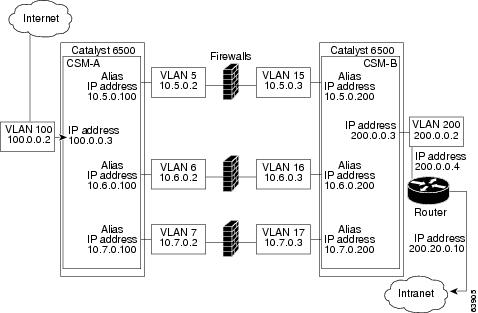
In Figure 5-1, traffic moves through the firewalls and is filtered in both directions. The figure shows the flow from the Internet to the intranet. On the path to the intranet, CSM A balances traffic across VLANs 5, 6, and 7 through firewalls to CSM B. On the path to the Internet, CSM B balances traffic across VLANs 15, 16, and 17 through firewalls to CSM A. CSM A uses the VLAN aliases of CSM B in its server farm, and CSM B uses the VLAN aliases of CSM A in its server farm.
Figure 5-1 Stealth Firewall Configuration (Dual CSMs Only)
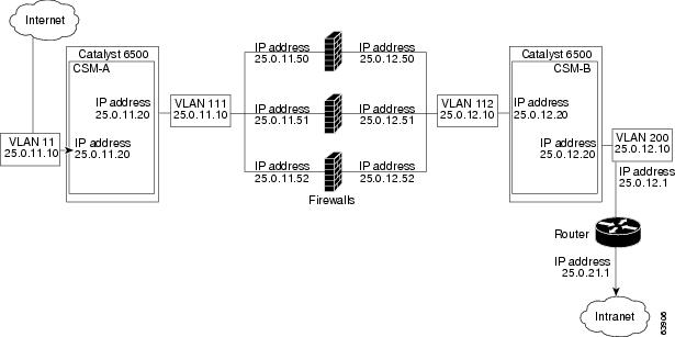
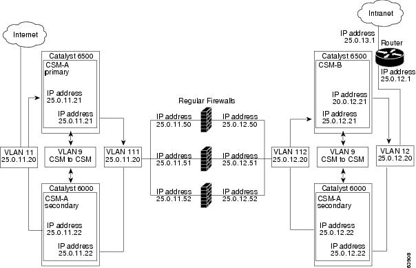
In Figure 5-2, traffic moves through the firewalls and is filtered in both directions. The figure shows the flow from the Internet to the intranet. VLANs 11 and 111 are on the same subnet, and
VLANs 12 and 112 are on the same subnet.
Figure 5-2 Regular Firewall Configuration (Dual CSMs)
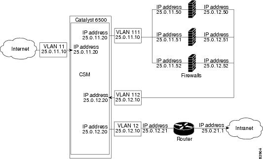
In Figure 5-3, traffic moves through the firewalls and is filtered in both directions. The figure shows only the flow from the Internet to the intranet, and VLANs 11 and 111 are on the same subnet.
VLANs 12 and 112 are on the same subnet.
Figure 5-3 Regular Firewall Configuration (Single CSM)
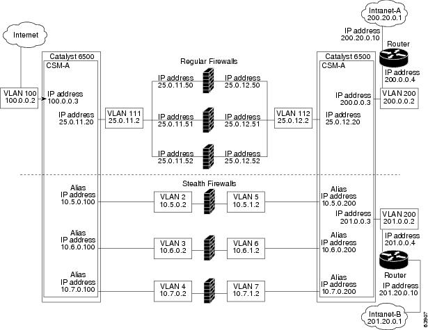
In Figure 5-4, traffic moves through both the regular and stealth firewalls and is filtered in both directions. The figure shows the flow from the Internet to the intranet. VLANs 5, 6, and 7 are shared between CSM A and CSM B. On the path to the intranet, CSM A balances traffic across VLANs 5, 6, and 7 through firewalls to CSM B. On the path to the intranet, CSM B balances traffic across VLANs 5, 6, and 7 through firewalls to CSM A.
Figure 5-4 Mixed Firewall Configuration for Stealth and Regular Firewalls (Dual CSMs Only)
Fault-Tolerant CSM Firewall Configurations
The CSM supports fault tolerance for these configurations:
•![]() Stealth firewalls in a fault-tolerant dual CSM configuration
Stealth firewalls in a fault-tolerant dual CSM configuration
•![]() Regular firewalls in a fault-tolerant dual CSM configuration
Regular firewalls in a fault-tolerant dual CSM configuration
•![]() Regular firewalls in a fault-tolerant single CSM configuration
Regular firewalls in a fault-tolerant single CSM configuration
•![]() Mixed firewalls (stealth and regular) in a fault-tolerant dual CSM configuration
Mixed firewalls (stealth and regular) in a fault-tolerant dual CSM configuration
In Figure 5-5, the traffic moves through the firewalls and is filtered in both directions. The figure only shows the flow from the Internet to the intranet through the primary CSMs, and VLANs 11 and 111 are on the same subnet. VLANs 12 and 112 are on the same subnet.
Figure 5-5 Fault-Tolerant, Regular Firewall Configuration-(Dual CSMs)
Configuring Stealth Firewall Load Balancing
This section describes how to configure firewall load balancing for stealth firewalls and covers the following information:
•![]() Packet flow in a stealth firewall configuration (dual CSMs)
Packet flow in a stealth firewall configuration (dual CSMs)
•![]() Stealth firewall configuration example
Stealth firewall configuration example
Stealth Firewall Configuration
In a stealth firewall configuration, firewalls connect to two different VLANs and are configured with IP addresses on the VLANs to which they connect. (See Figure 5-6.)
Figure 5-6 Stealth Firewall Configuration Example
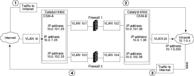
Figure 5-6 shows two regular firewalls (Firewall 1 and Firewall 2) sandwiched between two CSMs
(CSM A and CSM B).
Note ![]() Stealth firewalls do not have addresses on VLANs.
Stealth firewalls do not have addresses on VLANs.
On the path from the Internet to the intranet, traffic enters the insecure side of the firewalls through separate VLANs, VLAN 101 and VLAN 103, and exits the secure side of the firewalls through separate VLANs, VLAN 102 and VLAN 104. On the path from the intranet to the Internet, the flow is reversed. VLANs also provide connectivity to the Internet (VLAN 10) and to the intranet (VLAN 20).
In a stealth configuration, CSM A and CSM B load balance traffic through the firewalls.
Stealth Firewall Configuration Example
The stealth firewall configuration example contains two CSMs (CSM A and CSM B) installed in separate Catalyst 6500 series switches.
Note ![]() In a stealth firewall configuration, each CSM must be installed in a separate Catalyst 6500 series switch.
In a stealth firewall configuration, each CSM must be installed in a separate Catalyst 6500 series switch.
This section describes how to create the stealth firewall configuration for CSM A and CSM B.
Configuring CSM A (Stealth Firewall Example)
To create the regular configuration example, perform these tasks for CSM A:
•![]() Configuring Server Farms on CSM A
Configuring Server Farms on CSM A
•![]() Configuring Virtual Servers on CSM A
Configuring Virtual Servers on CSM A
Note ![]() Although the configuration tasks are the same for both for CSM A and CSM B, the steps, commands, and parameters that you enter are different.
Although the configuration tasks are the same for both for CSM A and CSM B, the steps, commands, and parameters that you enter are different.
Creating VLANs on Switch A
To create two VLANs on switch A, perform this task:
|
|
|
|
|---|---|---|
Step 1 |
Switch-A(config)# vlan database |
Enters the VLAN mode.1 |
Step 2 |
Switch-A(vlan)# vlan 10 |
Creates VLAN 102 . |
Step 3 |
Switch-A(vlan)# vlan 101 |
Creates VLAN 1013 . |
Step 4 |
Switch-A(vlan)# vlan 103 |
Creates VLAN 1034 . |
1 Perform this step on the switch console of the switch that contains CSM A. 2 VLAN 10 connects CSM A to the Internet. 3 VLAN 101 provides a connection through Firewall 1 to CSM B. 4 VLAN 103 provides a connection through Firewall 2 to CSM B |
Configuring VLANs on CSM A
To configure the three VLANs, perform this task:
|
|
|
|
|---|---|---|
Step 1 |
Switch-A(config)# module csm 5 |
Enters multiple module configuration mode and specifies that CSM A is installed in slot 5. |
Step 2 |
Switch-A(config-module-csm)# vlan 10 client |
Specifies VLAN 10 as the VLAN that is being configured, identifies it as a client VLAN, and enters VLAN configuration mode. |
Step 3 |
Switch-A(config-slb-vlan-client)# ip address 10.0.1.35 255.255.255.0 |
Specifies an IP address and netmask for VLAN 10. |
Step 4 |
Switch-A(config-slb-vlan-client)# alias 10.0.1.30 255.255.255.0 |
Specifies an alias IP address and netmask for VLAN 101 . |
Step 5 |
Switch-A(config-slb-vlan-client)# exit |
Returns to VLAN configuration mode. |
Step 6 |
Switch-A(config-module-csm)# vlan 101 server |
Specifies VLAN 101 as the VLAN that is being configured, identifies it as a server VLAN, and enters VLAN configuration mode. |
Step 7 |
Switch-A(config-slb-vlan-server)# ip address 10.0.101.35 255.255.255.0 |
Specifies an IP address and netmask for VLAN 101. |
Step 8 |
Switch-A(config-slb-vlan-server)# alias 10.0.101.100 255.255.255.0 |
Specifies an alias IP address and netmask for VLAN 1011. |
Step 9 |
Switch-A(config-slb-vlan-server)# exit |
Returns to VLAN configuration mode. |
Step 10 |
Switch-A(config-module-csm)# vlan 103 server |
Specifies VLAN 103 as the VLAN that is being configured, identifies it as a server VLAN, and enters VLAN configuration mode. |
Step 11 |
Switch-A(config-slb-vlan)# ip address 10.0.102.35 255.255.255.0 |
Specifies an IP address and netmask for VLAN 103. |
Step 12 |
Switch-A(config-slb-vlan)# alias 10.0.102.100 255.255.255.0 |
Specifies an alias IP address and netmask for VLAN 1031. |
1 This step provides a target for CSM B to use in making a load-balancing decision. |
Configuring Server Farms on CSM A
Note ![]() Because the IP addresses of CSM B are listed in the INSIDE-SF server farm as real servers, CSM A will load balance the two firewalls that exist in the path to CSM B.
Because the IP addresses of CSM B are listed in the INSIDE-SF server farm as real servers, CSM A will load balance the two firewalls that exist in the path to CSM B.
To configure two server farms on CSM A, perform this task:
|
|
|
|
|---|---|---|
Step 1 |
Switch-A(config)# module csm 5 |
Enters multiple module configuration mode and specifies that CSM A is installed in slot 5. |
Step 2 |
Switch-A(config-module-csm)# serverfarm FORWARD-SF |
Creates and names the FORWARD-SF1 server farm (actually a forwarding policy) and enters server farm configuration mode. |
Step 3 |
Switch-A(config-slb-sfarm)# no nat server |
Disables the NAT of server IP addresses and port numbers2 . |
Step 4 |
Switch-A(config-slb-sfarm)# predictor forward |
Forwards traffic in accordance with its internal routing tables rather than a load-balancing algorithm. |
Step 5 |
Switch-A(config-slb-sfarm)# exit |
Returns to multiple module configuration mode. |
Step 6 |
Switch-A(config-module-csm)# serverfarm TO-INSIDE-SF |
Creates and names the INSIDE-SF3 server farm (that will contain alias IP addresses rather than real servers) and enters server farm configuration mode. |
Step 7 |
Switch-A(config-slb-sfarm)# no nat server |
Disables the NAT of server IP address and port number4 . |
Step 8 |
Switch-A(config-slb-sfarm)# predictor hash address source 255.255.255.255 |
Selects a server using a hash value based on the source IP address5 . |
Step 9 |
Switch-A(config-slb-sfarm)# real 10.0.101.200 |
Identifies the alias IP address of CSM B that lies on the path to Firewall 1 as a real server and enters real server configuration submode. |
Step 10 |
Switch-A(config-slb-real)# inservice |
Enables the firewall. |
Step 11 |
Switch-A(config-slb-real)# exit |
Returns to server farm configuration mode. |
Step 12 |
Switch-A(config-slb-sfarm)# real 10.0.102.200 |
Identifies the alias IP address of CSM B that lies on the path to Firewall 2 as a real server and enters real server configuration submode. |
Step 13 |
Switch-A(config-slb-real)# inservice |
Enables the firewall. |
1 FORWARD-SF is actually a route forwarding policy, not an actual server farm, that allows traffic to reach the Internet (through VLAN 10). It does not contain any real servers. 2 This step is required when configuring a server farm that contains a forwarding policy rather than real servers. 3 INSIDE-SF contains the two alias IP addresses of CSM B listed as real servers that allow traffic from the intranet to reach CSM B. 4 This step is required when configuring a server farm that contains firewalls. 5 We recommend that you perform this step when configuring insecure-side firewall interfaces in a server farm. |
Configuring Virtual Servers on CSM A
To configure three virtual servers on CSM A, perform this task:
|
|
|
|
|---|---|---|
Step 1 |
Switch-A(config)# module csm 5 |
Enters multiple module configuration mode and specifies that the CSM A is installed in slot 5. |
Step 2 |
Switch-A(config-module-csm)# vserver FORWARD-V101 |
Specifies FORWARD-V1011 as the virtual server that is being configured and enters virtual server configuration mode. |
Step 3 |
Switch-A(config-slb-vserver)# virtual 0.0.0.0 0.0.0.0 any |
Specifies a match for any IP address and any protocol2 . |
Step 4 |
Switch-A(config-slb-vserver))# vlan 101 |
Specifies that the virtual server will only accept traffic arriving on VLAN 101, which is traffic arriving from the insecure side of the firewalls. |
Step 5 |
Switch-A(config-slb-vserver)# serverfarm FORWARD-SF |
Specifies the server farm for this virtual server3 . |
Step 6 |
Switch-A(config-slb-vserver)# inservice |
Enables the virtual server. |
Step 7 |
Switch-A(config-slb-vserver)# exit |
Returns to multiple module configuration mode. |
Step 8 |
Switch-A(config-module-csm)# vserver FORWARD-V103 |
Specifies FORWARD-V1034 as the virtual server that is being configured and enters virtual server configuration mode. |
Step 9 |
Switch-A(config-slb-vserver)# virtual 0.0.0.0 0.0.0.0 any |
Specifies a match for any IP address and any protocol5 . |
Step 10 |
Switch-A(config-slb-vserver))# vlan 103 |
Specifies that the virtual server will only accept traffic arriving on VLAN 103, which is traffic arriving from the insecure side of the firewalls. |
Step 11 |
Switch-A(config-slb-vserver)# serverfarm FORWARD-SF |
Specifies the server farm for this virtual server3. |
Step 12 |
Switch-A(config-slb-vserver)# inservice |
Enables the virtual server. |
Step 13 |
Switch-A(config-slb-vserver)# exit |
Returns to multiple module configuration mode. |
Step 14 |
Switch-A(config-module-csm)# vserver OUTSIDE-VS |
Specifies OUTSIDE-VS6 as the virtual server that is being configured and enters virtual server configuration mode. |
Step 15 |
Switch-A(config-slb-vserver)# virtual 10.1.0.0 255.255.255.0 any |
Specifies the IP address, netmask, and protocol (any) for this virtual server. Clients reach the server farm represented by this virtual server through this address. |
Step 16 |
Switch-A(config-slb-vserver))# vlan 10 |
Specifies that the virtual server will only accept traffic arriving on VLAN 10, which is traffic arriving from the Internet. |
Step 17 |
Switch-A(config-slb-vserver)# serverfarm TO-INSIDE-SF |
Specifies the server farm for this virtual server7 . |
Step 18 |
Switch-A(config-slb-vserver)# inservice |
Enables the virtual server. |
1 FORWARD-V101 allows Internet traffic to reach the insecure side of the firewalls (through VLAN 101). 2 Client matching is only limited by VLAN restrictions. (See Step 4.) 3 This server farm is actually a forwarding predictor rather than an actual server farm containing real servers. 4 FORWARD-V103 allows Internet traffic to reach the insecure side of the firewalls (through VLAN 103). 5 Clients will always match-only being limited by VLAN restrictions. (See Step 10.) 6 OUTSIDE-VS allows traffic from the Internet to reach CSM A (through VLAN 10). 7 The server farm contains the alias IP addresses of CSM B that lie along the path of Firewall 1 and Firewall 2. |
Configuring CSM B (Stealth Firewall Example)
To create the regular configuration example, perform the following configuration tasks for CSM B:
•![]() Configuring Server Farms on CSM B
Configuring Server Farms on CSM B
•![]() Configuring Virtual Servers on CSM B
Configuring Virtual Servers on CSM B
Note ![]() Although the configuration tasks are the same for both CSM A and CSM B, the steps, commands, and parameters that you enter are different.
Although the configuration tasks are the same for both CSM A and CSM B, the steps, commands, and parameters that you enter are different.
Creating VLANs on Switch B
To create three VLANs on Switch B, perform this task:
Note ![]() This example assumes that the CSMs are in separate Catalyst 6500 series switches. If they are in the same chassis, you can create all of the VLANs on the same Catalyst 6500 series switch console.
This example assumes that the CSMs are in separate Catalyst 6500 series switches. If they are in the same chassis, you can create all of the VLANs on the same Catalyst 6500 series switch console.
|
|
|
|
|---|---|---|
Step 1 |
Switch-B(config)# vlan database |
Enters the VLAN mode1 . |
Step 2 |
Switch-B(vlan)# vlan 102 |
Creates VLAN 1022 . |
Step 3 |
Switch-B(vlan)# vlan 104 |
Creates VLAN 1043 . |
Step 4 |
Switch-B(vlan)# vlan 200 |
Creates VLAN 2004 . |
1 Do this step on the switch console of the switch that contains CSM B. 2 VLAN 102 provides a connection through Firewall 1 to CSM A. 3 VLAN 104 provides a connection through Firewall 2 to CSM A. 4 VLAN 200 provides the connection to the internal network. |
Configuring VLANs on CSM B
To configure the three VLANs, perform this task:
|
|
|
|
|---|---|---|
Step 1 |
Switch-B(config)# module csm 6 |
Enters multiple module configuration mode and specifies that CSM B is installed in slot 6. |
Step 2 |
Switch-B(config-module-csm)# vlan 102 server |
Specifies VLAN 102 as the VLAN that is being configured, identifies it as a server VLAN, and enters VLAN configuration mode. |
Step 3 |
Switch-B(config-slb-vlan-server)# ip address 10.0.101.36 255.255.255.0 |
Specifies an IP address and netmask for VLAN 102. |
Step 4 |
Switch-B(config-slb-vlan-server)# alias 10.0.101.200 255.255.255.0 |
Specifies an alias IP address and netmask for VLAN 1021 . |
Step 5 |
Switch-B(config-slb-vlan-server)# exit |
Returns to multiple module configuration mode. |
Step 6 |
Switch-B(config-module-csm)# vlan 104 server |
Specifies VLAN 104 as the VLAN that is being configured, identifies it as a server VLAN, and enters VLAN configuration mode. |
Step 7 |
Switch-B(config-slb-vlan-server)# ip address 10.0.102.36 255.255.255.0 |
Specifies an IP address and netmask for VLAN 104. |
Step 8 |
Switch-B(config-slb-vlan)# alias 10.0.102.200 255.255.255.0 |
Specifies an alias IP address and netmask for VLAN 1041. |
Step 9 |
Switch-B(config-slb-vlan-server)# exit |
Returns to multiple module configuration mode. |
Step 10 |
Switch-B(config-module-csm)# vlan 20 server |
Specifies VLAN 20 as the VLAN that is being configured, identifies it as a server VLAN, and enters VLAN configuration mode. |
Step 11 |
Switch-B(config-slb-vlan-server)# ip address 10.1.0.36 255.255.255.0 |
Specifies an IP address and netmask for VLAN 20. |
1 This step provides a target for CSM A to use in making a load-balancing decision. |
Configuring Server Farms on CSM B
To configure three server farms on CSM B, perform this task:
Note ![]() SERVERS-SF specifies that client NAT will be performed using a pool of client NAT addresses that are created earlier in the example using the natpool command. You must create the NAT pool before referencing the command.
SERVERS-SF specifies that client NAT will be performed using a pool of client NAT addresses that are created earlier in the example using the natpool command. You must create the NAT pool before referencing the command.
|
|
|
|
|---|---|---|
Step 1 |
Switch-B(config)# module csm 6 |
Enters multiple module configuration mode and specifies that CSM B is installed in slot 6. |
Step 2 |
Switch-B(config-module-csm)# serverfarm FORWARD-SF |
Creates and names the FORWARD-SF1 server farm (actually a forwarding policy) and enters server farm configuration mode. |
Step 3 |
Switch-B(config-slb-sfarm)# no nat server |
Disables the NAT of server IP addresses and port numbers2 . |
Step 4 |
Switch-B(config-slb-sfarm)# predictor forward |
Forwards traffic in accordance with its internal routing tables rather than a load-balancing algorithm. |
Step 5 |
Switch-B(config-slb-sfarm)# exit |
Returns to multiple module configuration mode. |
Step 6 |
Switch-B(config-module-csm)# serverfarm TO-OUTSIDE-SF |
Creates and names the GENERIC-SF server farm and enters server farm configuration mode3 . |
Step 7 |
Switch-B(config-slb-sfarm)# no nat server |
Disables NAT of server IP addresses and port numbers4 . |
Step 8 |
Switch-B(config-slb-sfarm)# real 10.0.101.100 |
Identifies the alias IP address of CSM A that lies on the path to Firewall 1 as a real server and enters real server configuration submode. |
Step 9 |
Switch-B(config-slb-real)# inservice |
Enables the real (actually an alias IP address). |
Step 10 |
Switch-B(config-slb-real)# exit |
Returns to server farm configuration mode. |
Step 11 |
Switch-B(config-slb-sfarm)# real 10.0.102.100 |
Identifies the alias IP address of CSM B that lies on the path to Firewall 2 as a real server and enters real server configuration submode. |
Step 12 |
Switch-B(config-slb-real)# inservice |
Enables the real server (actually an alias IP address). |
Step 13 |
Switch-B(config-slb-real)# exit |
Returns to server farm configuration mode. |
Step 14 |
Switch-B(config-module-csm)# serverfarm SERVERS-SF |
Creates and names the SERVERS-SF5 server farm and enters serverfarm configuration mode. |
Step 15 |
Switch-B(config-slb-sfarm)# real 10.1.0.101 |
Identifies a server in the intranet as a real server, assigns it an IP address, and enters real server configuration submode. |
Step 16 |
Switch-B(config-slb-real)# inservice |
Enables the real server. |
Step 17 |
Switch-B(config-slb-real)# exit |
Returns to server farm configuration mode. |
Step 18 |
Switch-B(config-slb-sfarm)# real 10.1.0.102 |
Identifies a server in the intranet as a real server, assigns it an IP address, and enters real server configuration submode. |
Step 19 |
Switch-B(config-slb-real)# inservice |
Enables the real server. |
Step 20 |
Switch-B(config-slb-sfarm)# real 10.1.0.103 |
Identifies a server in the intranet as a real server, assigns it an IP address, and enters real server configuration submode. |
Step 21 |
Switch-B(config-slb-real)# inservice |
Enables the real server. |
1 FORWARD-SF is actually a route forwarding policy, not an actual server farm, that allows traffic to reach the intranet (through VLAN 20). It does not contain any real servers. 2 This step is required when configuring a server farm that contains a forwarding policy rather than real servers. 3 OUTSIDE-SF contains the two alias IP addresses of CSM A as the real servers allowing traffic from the intranet to reach CSM A. 4 This step is required when configuring a server farm that contains a forwarding policy rather than real servers. 5 SERVERS-SF contains the IP addresses of the real servers located within the intranet. |
Configuring Virtual Servers on CSM B
To configure three virtual servers on CSM, perform this task:
|
|
|
|
|---|---|---|
Step 1 |
Switch-B(config)# module csm 6 |
Enters multiple module configuration mode and specifies that CSM B is installed in slot 6. |
Step 2 |
Switch-B(config-module-csm)# vserver FORWARD-VS-102 |
Specifies FORWARD-VS as the virtual server that is being configured and enters virtual server configuration mode. |
Step 3 |
Switch-B(config-slb-vserver)# virtual 0.0.0.0 0.0.0.0 any |
Specifies a match for any IP address and any protocol1 . |
Step 4 |
Switch-B(config-slb-vserver)# vlan 102 |
Specifies that the virtual server will only accept traffic arriving on VLAN 102, which is traffic arriving from the secure side of the Firewall 1. |
Step 5 |
Switch-B(config-slb-vserver)# serverfarm FORWARD-SF |
Specifies the server farm for this virtual server2 . |
Step 6 |
Switch-B(config-slb-vserver)# inservice |
Enables the virtual server. |
Step 7 |
Switch-B(config-slb-vserver)# exit |
Returns to multiple module configuration mode. |
Step 8 |
Switch-B(config-module-csm)# vserver FORWARD-VS-104 |
Specifies FORWARD-VS3 as the virtual server that is being configured and enters virtual server configuration mode. |
Step 9 |
Switch-B(config-slb-vserver)# virtual 0.0.0.0 0.0.0.0 any |
Specifies a match for any IP address and any protocol1. |
Step 10 |
Switch-B(config-slb-vserver)# vlan 104 |
Specifies that the virtual server will only accept traffic arriving on VLAN 104, which is traffic arriving from the secure side of the Firewall 2. |
Step 11 |
Switch-B(config-slb-vserver)# serverfarm FORWARD-SF |
Specifies the server farm for this virtual server2. |
Step 12 |
Switch-B(config-slb-vserver)# inservice |
Enables the virtual server. |
Step 13 |
Switch-B(config-slb-vserver)# exit |
Returns to multiple module configuration mode. |
Step 14 |
Switch-B(config-module-csm)# vserver INSIDE-VS |
Specifies INSIDE-VS4 as the virtual server that is being configured and enters virtual server configuration mode. |
Step 15 |
Switch-B(config-slb-vserver)# virtual 0.0.0.0 0.0.0.0 any |
Specifies a match for any IP address and any protocol1. |
Step 16 |
Switch-B(config-slb-vserver)# vlan 20 |
Specifies that the virtual server will only accept traffic arriving on VLAN 20, which is traffic arriving from the intranet. |
Step 17 |
Switch-B(config-slb-vserver)# serverfarm TO-OUTSIDE-SF |
Specifies the server farm for this virtual server (containing the alias IP addresses of CSM A as real servers and allowing traffic to flow through Firewalls 1 and 2) and enters real server configuration submode. |
Step 18 |
Switch-B(config-slb-vserver)# inservice |
Enables the virtual server. |
Step 19 |
Switch-B(config-slb-vserver)# exit |
Returns to multiple module configuration mode. |
Step 20 |
Switch-B(config-module-csm)# vserver TELNET-VS |
Specifies TELNET-VS5 as the virtual server that is being configured and enters virtual server configuration mode. Note |
Step 21 |
Switch-B(config-slb-vserver)# virtual 10.1.0.200 255.255.255.0 tcp telnet |
Specifies the IP address, netmask, protocol (TCP), and port (Telnet) for this virtual server6 . |
Step 22 |
Switch-B(config-slb-vserver)# serverfarm SERVERS-SF |
Specifies the server farm containing real servers for this virtual server. |
Step 23 |
Switch-B(config-slb-vserver)# inservice |
Enables the virtual server. |
1 Client matching is only limited by VLAN restrictions. 2 This server farm is actually a forwarding predictor rather than an actual server farm containing real servers. 3 FORWARD-VS allows traffic from the Internet to reach the intranet through VLAN 20. 4 INSIDE-VS allows traffic from the intranet to reach CSM A through Firewall 1 (through VLANs 102 and 101) or 5 TELNET-VS allows traffic from the Internet to reach Telnet servers in the internal network. 6 Clients reach the server farm represented by this virtual server through this address. |
Configuring Regular Firewall Load Balancing
This section describes how to configure firewall load balancing for regular firewalls and provides the following information:
•![]() Packet flow in a regular firewall configuration (dual CSMs)
Packet flow in a regular firewall configuration (dual CSMs)
•![]() Regular firewall configuration example
Regular firewall configuration example
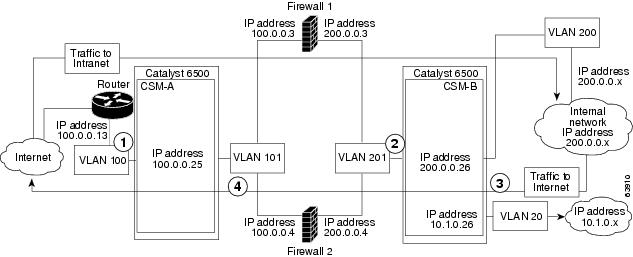
Packet Flow in a Regular Firewall Configuration
In a regular firewall configuration, firewalls connect to two different VLANs and are configured with IP addresses on the VLANs to which they connect. (See Figure 5-7.)
Figure 5-7 Regular Firewall Configuration Example
|
|
|
|
|
|---|---|---|---|
|
|
To intranet |
VLAN 100 |
VLANs 101 |
|
|
To intranet |
VLANs 201 |
VLAN 200 and 20 |
|
|
To Internet |
VLAN 200 and 20 |
VLANs 201 |
|
|
To Internet |
VLANs 101 |
VLAN 100 |
Figure 5-7 shows two regular firewalls (Firewall 1 and Firewall 2) located between two CSMs
(CSM A and CSM B). Traffic enters and exits the firewalls through shared VLANs (VLAN 101 and VLAN 201). Both regular firewalls have unique addresses on each shared VLAN.
VLANs provide connectivity to the Internet (VLAN 100), the internal network (VLAN 200), and to internal server farms (VLAN 20).
The CSM balances traffic among regular firewalls as if they were real servers. Regular firewalls are configured in server farms with IP addresses like real servers. The server farms to which regular firewalls belong are assigned a load-balancing predictor and are associated with virtual servers.
Regular Firewall Configuration Example
The regular firewall configuration example contains two CSMs (CSM A and CSM B) installed in separate Catalyst 6500 series switches.
Note ![]() You can use this example when configuring two CSMs in the same Catalyst 6500 series switch chassis. You can also use this example when configuring a single CSM in a single switch chassis, assuming that you specify the slot number of that CSM when configuring both CSM A and CSM B.
You can use this example when configuring two CSMs in the same Catalyst 6500 series switch chassis. You can also use this example when configuring a single CSM in a single switch chassis, assuming that you specify the slot number of that CSM when configuring both CSM A and CSM B.
Configuring CSM A (Regular Firewall Example)
To create the regular configuration example, perform the following configuration tasks for CSM A:
•![]() Configuring Server Farms on CSM A
Configuring Server Farms on CSM A
•![]() Configuring Virtual Servers on CSM A
Configuring Virtual Servers on CSM A
Note ![]() Although the configuration tasks are the same for both CSM A and CSM B, the steps, commands, and parameters that you enter are different.
Although the configuration tasks are the same for both CSM A and CSM B, the steps, commands, and parameters that you enter are different.
Creating VLANs on Switch A
The example, shown in Figure 5-7, requires that you create two VLANs on Switch A.
Note ![]() This example assumes that the CSMs are in separate Catalyst 6500 series switch chassis. If they are in the same chassis, all of the VLANs can be created on the same Catalyst 6500 series switch console.
This example assumes that the CSMs are in separate Catalyst 6500 series switch chassis. If they are in the same chassis, all of the VLANs can be created on the same Catalyst 6500 series switch console.
To configure VLANs on Switch A, perform this task:
|
|
|
|
|---|---|---|
Step 1 |
Switch-A(config)# vlan database |
Enters the VLAN mode1 . |
Step 2 |
Switch-A(vlan)# vlan 100 |
Creates VLAN 1002 . |
Step 3 |
Switch-A(vlan)# vlan 101 |
Creates VLAN 1013 . |
1 Do this step on the switch console of the switch that contains CSM A. 2 VLAN 100 connects CSM A to the Internet. 3 VLAN 101 connects CSM A to the insecure side of the firewalls. |
Configuring VLANs on CSM A
To configure the two VLANs, perform this task:
|
|
|
|
|---|---|---|
Step 1 |
Switch-A(config)# module csm 5 |
Enters multiple module configuration mode and specifies that CSM A is installed in slot 5. |
Step 2 |
Switch-A(config-module-csm)# vlan 100 client |
Specifies VLAN 100 as the VLAN that is being configured, identifies it as a client VLAN, and enters VLAN configuration mode. |
Step 3 |
Switch-A(config-slb-vlan-client)# ip address 100.0.0.25 255.255.255.0 |
Specifies an IP address and netmask for VLAN 100. |
Step 4 |
Switch-A(config-slb-vlan-client)# gateway 100.0.0.13 |
Configures a gateway IP address for the router on the Internet side of CSM A. |
Step 5 |
Switch-A(config-slb-vlan-client)# exit |
Returns to multiple module configuration mode. |
Step 6 |
Switch-A(config-module-csm)# vlan 101 server |
Specifies VLAN 101 as the VLAN that is being configured, identifies it as a server VLAN, and enters VLAN configuration mode. |
Step 7 |
Switch-A(config-slb-vlan-server)# ip address 100.0.0.25 255.255.255.0 |
Specifies an IP address and netmask for VLAN 101. |
Step 8 |
Switch-A(config-slb-vlan-server)# alias 100.0.0.20 255.255.255.0 |
Specifies an alias IP address and netmask for VLAN 1011 . |
1 This step provides a target for CSM B to use in making a load-balancing decision. |
Configuring Server Farms on CSM A
Note ![]() Firewall 1 and Firewall 2 secure-side IP addresses are configured as real servers in the SEC-SF server farm associated with CSM B.
Firewall 1 and Firewall 2 secure-side IP addresses are configured as real servers in the SEC-SF server farm associated with CSM B.
To configure two server farms on CSM A, perform this task:
|
|
|
|
|---|---|---|
Step 1 |
Switch-A(config)# module csm 5 |
Enters multiple module configuration mode and specifies that CSM A is installed in slot 5. |
Step 2 |
Switch-A(config-module-csm)# serverfarm FORWARD-SF |
Creates and names the FORWARD-SF1 server farm (actually a forwarding policy) and enters server farm configuration mode. |
Step 3 |
Switch-A(config-slb-sfarm)# no nat server |
Disables the NAT of server IP addresses and port numbers2 . |
Step 4 |
Switch-A(config-slb-sfarm)# predictor forward |
Forwards traffic by adhering to its internal routing tables rather than a load-balancing algorithm. |
Step 5 |
Switch-A(config-slb-sfarm)# exit |
Returns to multiple module configuration mode. |
Step 6 |
Switch-A(config-module-csm)# serverfarm INSEC-SF |
Creates and names the INSEC-SF3 server farm (which will contain firewalls as real servers) and enters server farm configuration mode. |
Step 7 |
Switch-A(config-slb-sfarm)# no nat server |
Disables the NAT of server IP address and port number4 . |
Step 8 |
Switch-A(config-slb-sfarm)# predictor hash address source 255.255.255.255 |
Selects a server using a hash value based on the source IP address5 . |
Step 9 |
Switch-A(config-slb-sfarm)# real 100.0.0.3 |
Identifies Firewall 1 as a real server, assigns an IP address to its insecure side, and enters real server configuration submode. |
Step 10 |
Switch-A(config-slb-real)# inservice |
Enables the firewall. |
Step 11 |
Switch-A(config-slb-real)# exit |
Returns to server farm configuration mode. |
Step 12 |
Switch-A(config-slb-sfarm)# real 100.0.0.4 |
Identifies Firewall 2 as a real server, assigns an IP address to its insecure side, and enters real server configuration submode. |
Step 13 |
Switch-A(config-slb-real)# inservice |
Enables the firewall. |
1 FORWARD-SF is actually a route forwarding policy, not an actual server farm, that allows traffic to reach the Internet (through VLAN 100); it does not contain any real servers. 2 This is a required step when configuring a server farm that contains a forwarding policy rather than real servers. 3 INSEC-SF contains (Firewall 1 and Firewall 2); their insecure-side IP addresses are configured as real servers in this server farm. 4 This is a required step when configuring a server farm that contains firewalls. 5 We recommend this step when configuring insecure-side firewall interfaces in a server farm. |
Configuring Virtual Servers on CSM A
To configure two virtual servers on CSM A, perform this task:
|
|
|
|
|---|---|---|
Step 1 |
Switch-A(config)# module csm 5 |
Enters multiple module configuration mode and specifies that the CSM A is installed in slot 5. |
Step 2 |
Switch-A(config-module-csm)# vserver FORWARD-VS |
Specifies FORWARD-VS1 as the virtual server that is being configured and enters virtual server configuration mode. |
Step 3 |
Switch-A(config-slb-vserver)# virtual 0.0.0.0 0.0.0.0 any |
Specifies a match for any IP address and any protocol2 . |
Step 4 |
Switch-A(config-slb-vserver))# vlan 101 |
Specifies that the virtual server will only accept traffic arriving on VLAN 101, which is traffic arriving from the insecure side of the firewalls. |
Step 5 |
Switch-A(config-slb-vserver)# serverfarm FORWARD-SF |
Specifies the server farm for this virtual server3 . |
Step 6 |
Switch-A(config-slb-vserver)# inservice |
Enables the virtual server. |
Step 7 |
Switch-A(config-slb-vserver)# exit |
Returns to multiple module configuration mode. |
Step 8 |
Switch-A(config-module-csm)# vserver INSEC-VS |
Specifies INSEC-VS4 as the virtual server that is being configured and enters virtual server configuration mode. |
Step 9 |
Switch-A(config-slb-vserver)# virtual 200.0.0.0 255.255.255.0 any |
Specifies the IP address, netmask, and protocol (any) for this virtual server5 . |
Step 10 |
Switch-A(config-slb-vserver))# vlan 100 |
Specifies that the virtual server will only accept traffic arriving on VLAN 100, which is traffic arriving from the Internet. |
Step 11 |
Switch-A(config-slb-vserver)# serverfarm INSEC-SF |
Specifies the server farm for this virtual server6 . |
Step 12 |
Switch-A(config-slb-vserver)# inservice |
Enables the virtual server. |
1 FORWARD-VS allows Internet traffic to reach the insecure side of the firewalls (through VLAN 101). 2 Client matching is only limited by VLAN restrictions. (See Step 4.) 3 This server farm is actually a forwarding predictor rather than an actual server farm containing real servers. 4 INSEC-VS allows traffic from the Internet to reach CSM A (through VLAN 101). 5 Clients reach the server farm represented by this virtual server through this address. 6 The server farm contains firewalls rather than real servers. |
Configuring CSM B (Regular Firewall Example)
To create the regular configuration example, perform the following configuration tasks for CSM B:
•![]() Configuring Server Farms on CSM B
Configuring Server Farms on CSM B
•![]() Configuring Virtual Servers on CSM B
Configuring Virtual Servers on CSM B
Note ![]() Although the configuration tasks are the same for both CSM A and CSM B, the steps, commands, and parameters that you enter are different.
Although the configuration tasks are the same for both CSM A and CSM B, the steps, commands, and parameters that you enter are different.
Creating VLANs on Switch B
Note ![]() This example assumes that the CSMs are in separate Catalyst 6500 series switch chassis. If they are in the same chassis, all of the VLANs can be created on the same Catalyst 6500 series switch console.
This example assumes that the CSMs are in separate Catalyst 6500 series switch chassis. If they are in the same chassis, all of the VLANs can be created on the same Catalyst 6500 series switch console.
To create three VLANs on Switch B, perform this task:
|
|
|
|
|---|---|---|
Step 1 |
Switch-B(config)# vlan database |
Enters the VLAN mode1 . |
Step 2 |
Switch-B(vlan)# vlan 201 |
Creates VLAN 2012 . |
Step 3 |
Switch-B(vlan)# vlan 200 |
Creates VLAN 2003 . |
Step 4 |
Switch-B(vlan)# vlan 20 |
Creates VLAN 204 . |
1 Do this step on the switch console of the switch that contains CSM B. 2 VLAN 201 provides the connection to the secure side of the firewalls. 3 VLAN 20 provides the connection to the internal server farms. 4 VLAN 200 provides the connection to the internal network. |
Configuring VLANs on CSM B
To configure the three VLANs on CSM B, perform this task:
|
|
|
|
|---|---|---|
Step 1 |
Switch-B(config)# module csm 6 |
Enters multiple module configuration mode and specifies that CSM B is installed in slot 6. |
Step 2 |
Switch-B(config-module-csm)# vlan 201 server |
Specifies VLAN 201 as the VLAN that is being configured, identifies it as a server VLAN, and enters VLAN configuration mode. |
Step 3 |
Switch-B(config-slb-vlan-server)# ip address 200.0.0.26 255.255.255.0 |
Specifies an IP address and netmask for VLAN 201. |
Step 4 |
Switch-B(config-slb-vlan-server)# alias 200.0.0.20 255.255.255.0 |
Specifies an alias IP address and netmask for VLAN 2011 . |
Step 5 |
Switch-B(config-slb-vlan-server)# exit |
Returns to VLAN configuration mode. |
Step 6 |
Switch-B(config-module-csm)# vlan 20 server |
Specifies VLAN 20 as the VLAN that is being configured, identifies it as a server VLAN, and enters VLAN configuration mode. |
Step 7 |
Switch-B(config-slb-vlan-server)# ip address 10.1.0.26 255.255.255.0 |
Specifies an IP address and netmask for VLAN 20. |
Step 8 |
Switch-B(config-slb-vlan-server)# exit |
Returns to VLAN configuration mode. |
Step 9 |
Switch-B(config-module-csm)# vlan 200 client |
Specifies VLAN 200 as the VLAN that is being configured, identifies it as a client VLAN, and enters VLAN configuration mode. |
Step 10 |
Switch-B(config-slb-vlan)# ip address 200.0.0.26 255.255.255.0 |
Specifies an IP address and netmask for VLAN 200. |
1 This step provides a target for CSM A to use in making a load-balancing decision. |
Configuring Server Farms on CSM B
Note ![]() Firewall 1 and Firewall 2 secure-side IP addresses are configured as real servers in the INSEC-SF server farm associated with CSM A.
Firewall 1 and Firewall 2 secure-side IP addresses are configured as real servers in the INSEC-SF server farm associated with CSM A.
To configure two server farms on CSM B, perform this task:
|
|
|
|
|---|---|---|
Step 1 |
Switch-B(config)# module csm 6 |
Enters multiple module configuration mode and specifies that CSM B is installed in slot 6. |
Step 2 |
Switch-B(config-module-csm)# serverfarm GENERIC-SF |
Creates and names the GENERIC-SF1 server farm and enters server farm configuration mode. |
Step 3 |
Switch-B(config-slb-sfarm)# real 10.1.0.101 |
Identifies a server in the internal server farm as a real server, assigns it an IP address, and enters real server configuration submode. |
Step 4 |
Switch-B(config-slb-real)# inservice |
Enables the real server. |
Step 5 |
Switch-B(config-slb-real)# exit |
Returns to server farm configuration mode. |
Step 6 |
Switch-B(config-slb-sfarm)# real 10.1.0.102 |
Identifies a server in the internal server farm as a real server, assigns it an IP address, and enters real server configuration submode. |
Step 7 |
Switch-B(config-slb-real)# inservice |
Enables the real server. |
Step 8 |
Switch-B(config-slb-real)# exit |
Returns to server farm configuration mode. |
Step 9 |
Switch-B(config-slb-sfarm)# exit |
Returns to multiple module configuration mode. |
Step 10 |
Switch-B(config-module-csm)# serverfarm SEC-SF |
Creates and names the SEC-SF2 server farm and enters server farm configuration mode. |
Step 11 |
Switch-B(config-slb-sfarm)# no nat server |
Disables the NAT of server IP address and port number3 . |
Step 12 |
Switch-B(config-slb-sfarm)# predictor hash address destination 255.255.255.255 |
Selects a server using a hash value based on the destination IP address4 . |
Step 13 |
Switch-B(config-slb-sfarm)# real 200.0.0.3 |
Identifies Firewall 1 as a real server, assigns an IP address to its insecure side, and enters real server configuration submode. |
Step 14 |
Switch-B(config-slb-real)# inservice |
Enables the firewall. |
Step 15 |
Switch-B(config-slb-real)# exit |
Returns to server farm configuration mode. |
Step 16 |
Switch-B(config-slb-sfarm)# real 200.0.0.4 |
Identifies Firewall 2 as a real server, assigns an IP address to its insecure side, and enters real server configuration submode. |
Step 17 |
Switch-B(config-slb-real)# inservice |
Enables the firewall. |
1 GENERIC-SF contains the real servers in the internal server farm. 2 SEC-SF contains (firewall 1 and firewall 2)-their secure-side IP addresses are configured as real servers in this server farm. 3 This is a required step when configuring a server farm that contains firewalls. 4 We recommend this step when configuring secure-side firewall interfaces in a server farm. |
Configuring Virtual Servers on CSM B
To configure three virtual servers on CSM B, perform this task:
|
|
|
|
|---|---|---|
Step 1 |
Switch-B(config)# module csm 6 |
Enters multiple module configuration mode and specifies that CSM B is installed in slot 6. |
Step 2 |
Switch-B(config-module-csm)# vserver GENERIC-VS |
Specifies GENERIC-VS1 as the virtual server that is being configured and enters virtual server configuration mode. |
Step 3 |
Switch-B(config-slb-vserver)# virtual 200.0.0.127 tcp 0 |
Specifies the IP address, protocol (TCP), and port (0=any) for this virtual server2 . |
Step 4 |
Switch-B(config-slb-vserver))# vlan 201 |
Specifies that the virtual server will only accept traffic arriving on VLAN 201, which is traffic arriving from the secure side of the firewalls. |
Step 5 |
Switch-B(config-slb-vserver)# serverfarm GENERIC-SF |
Specifies the server farm for this virtual server3 . |
Step 6 |
Switch-B(config-slb-vserver)# inservice |
Enables the virtual server. |
Step 7 |
Switch-B(config-slb-vserver)# exit |
Returns to multiple module configuration mode. |
Step 8 |
Switch-B(config-module-csm)# vserver SEC-20-VS |
Specifies SEC-20-VS4 as the virtual server that is being configured and enters virtual server configuration mode. |
Step 9 |
Switch-B(config-slb-vserver)# virtual 200.0.0.0 255.255.255.0 any |
Specifies the IP address, netmask, and protocol (any) for this virtual server2. |
Step 10 |
Switch-B(config-slb-vserver))# vlan 20 |
Specifies that the virtual server will only accept traffic arriving on VLAN 20, which is traffic arriving from the internal server farms. |
Step 11 |
Switch-B(config-slb-vserver)# serverfarm SEC-SF |
Specifies the server farm for this virtual server5 . |
Step 12 |
Switch-B(config-slb-vserver)# inservice |
Enables the virtual server. |
Step 13 |
Switch-B(config-slb-vserver)# exit |
Returns to multiple module configuration mode. |
Step 14 |
Switch-B(config-module-csm)# vserver SEC-200-VS |
Specifies SEC-20-VS6 as the virtual server that is being configured and enters virtual server configuration mode. |
Step 15 |
Switch-B(config-slb-vserver)# virtual 200.0.0.0 255.255.255.0 any |
Specifies the IP address, netmask, and protocol (any) for this virtual server2. |
Step 16 |
Switch-B(config-slb-vserver))# vlan 200 |
Specifies that the virtual server will only accept traffic arriving on VLAN 200, which is traffic arriving from the internal network. |
Step 17 |
Switch-B(config-slb-vserver)# serverfarm SEC-SF |
Specifies the server farm for this virtual server5. |
Step 18 |
Switch-B(config-slb-vserver)# inservice |
Enables the virtual server. |
1 GENERIC-VS allows traffic from the internal server farms and the internal network that is destined for the Internet to reach the secure side of the firewalls (through VLAN 101). 2 Clients reach the server farm represented by this virtual server through this address. 3 The server farm exists in the internal server farms network. 4 SEC-20-VS allows traffic from the Internet to reach the internal server farms (through VLAN 20). 5 The server farm contains firewalls rather than real servers. 6 SEC-200-VS allows traffic from the Internet to reach the internal network (through VLAN 20). |
Configuring Reverse-Sticky for Firewalls
reverse-sticky operates by creating a database of load-balancing decisions based on the client's IP address. This feature over-rides the load-balancing decision when a reverse-sticky entry is available in the database. If there is no reverse-sticky entry in the database, a load balancing decision takes place, and the result is stored for future matching.
Understanding Reverse-Sticky for Firewalls
reverse-sticky is a way of inserting entries into a sticky database as if the connection came from the other direction. A virtual server with reverse-sticky places an entry into the specified database containing the inbound real server.
Note ![]() The inbound real server MUST be a real server within a serverfarm.
The inbound real server MUST be a real server within a serverfarm.
This entry is matched by a sticky command on a different virtual server. The other virtual server sends traffic to the client, based on this pregenerated entry.
The CSM stores reverse-sticky information as links from a source IP key to a real server. When the load balancer gets a new session on a virtual server with an assigned sticky database, it first checks the database for an existing entry. If a matching entry is found, the session is connected to the specified real server. Otherwise, a new entry is created linking the sticky key with the appropriate real server. Figure 5-8 shows how the reverse-sticky feature is used for firewalls.
Figure 5-8 Reverse-Sticky for Firewalls
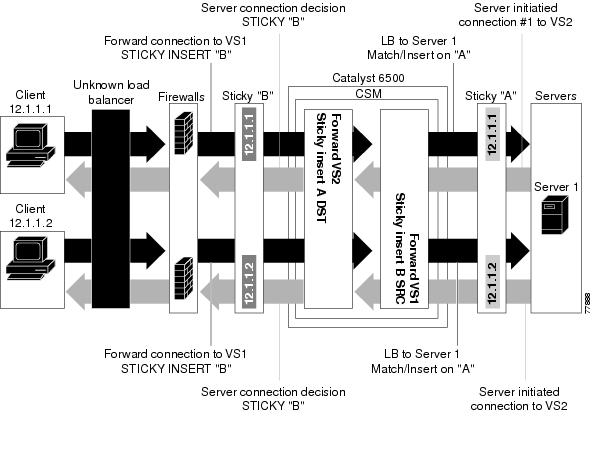
As shown in Figure 5-8, the reverse-sticky process is as follows:
•![]() A client connects to the CSM virtual server, VS1, through a load-balanced firewall. This load balancing decision is made without interaction with the CSM.
A client connects to the CSM virtual server, VS1, through a load-balanced firewall. This load balancing decision is made without interaction with the CSM.
•![]() Configure VS1 with cookie insert, so VS1 can insert a sticky entry into database B based on SRC pointing to firewall 1. This connection is used later by VS2 VS1 also performs a normal sticky to Server 1.
Configure VS1 with cookie insert, so VS1 can insert a sticky entry into database B based on SRC pointing to firewall 1. This connection is used later by VS2 VS1 also performs a normal sticky to Server 1.
•![]() Server 1 creates a connection back to the original client. This connection matches virtual server VS2. VS2 uses the sticky information inserted by the original VS1 reverse-sticky. Now the connection is forced to the same firewall 1.
Server 1 creates a connection back to the original client. This connection matches virtual server VS2. VS2 uses the sticky information inserted by the original VS1 reverse-sticky. Now the connection is forced to the same firewall 1.
•![]() A second client, coming in through a different firewall, will hit the same VS1. Reverse-sticky creates a new entry into database B for the second client, pointing to Firewall 2. VS1 also performs a normal sticky to Server 1.
A second client, coming in through a different firewall, will hit the same VS1. Reverse-sticky creates a new entry into database B for the second client, pointing to Firewall 2. VS1 also performs a normal sticky to Server 1.
•![]() Server 1 creates a connection back to Client 2. The connection matches the connection in VS2. VS2 uses the sticky information inserted by the original VS1 reverse-sticky. This connection is used for the connection to Firewall 2.
Server 1 creates a connection back to Client 2. The connection matches the connection in VS2. VS2 uses the sticky information inserted by the original VS1 reverse-sticky. This connection is used for the connection to Firewall 2.
•![]() If the server had originated the first connection, the link back to the server would have been inserted by VS2, and a normal load balancing decision would have generated a connection to one of the firewalls.
If the server had originated the first connection, the link back to the server would have been inserted by VS2, and a normal load balancing decision would have generated a connection to one of the firewalls.
Note ![]() This configuration supports forward direction connections (client to server) using any balancing metric. However, the balancing metric to the firewalls from VS2 must match that of the unknown load balancer, or the unknown load balancer must stick new buddy connections in a similar manner if client responses to server initiated traffic are to be sent to the correct firewall.
This configuration supports forward direction connections (client to server) using any balancing metric. However, the balancing metric to the firewalls from VS2 must match that of the unknown load balancer, or the unknown load balancer must stick new buddy connections in a similar manner if client responses to server initiated traffic are to be sent to the correct firewall.
Reverse-Sticky for Firewalls Configuration Example
To configure IP reverse-sticky for firewall load balancing, perform this task:
Configuring Generic Header Parsing
In software release 2.1(1), the CSM supports generic HTTP request header parsing. The HTTP request header contains fields that describe how content should be formatted to meet the user's requirements.
Understanding Generic Header Parsing
The CSM uses the information it learns by parsing and matching fields in the HTTP header along with policy information to make load-balancing decisions. For example, by parsing the browser-type field in the HTTP header, the CSM can determine if a user is accessing the content with a mobile browser and can select a server that contains content formatted for a mobile browser.
An example of a HTTP Get request header record is as follows:
GET /?u HTTP/1.1<0D><0A>
Accept: image/gif, image/x-xbitmap, image/jpeg, image/pjpeg<0D><0A>
Referer: http://www.yahoo.com/<0D><0A>
Accept-Language: en-us<0D><0A>
Accept-Encoding: gzip, deflate<0D><0A>
User-Agent: Mozilla/4.0 (compatible; MSIE 5.0; Windows NT; DigExt)<0D><0A>
Host: finance.yahoo.com<0D><0A>
Connection: Keep-Alive<0D><0A>
Cookie: B=51g3cjstaq3vm; Y=1<0D><0A>
<0D><0A>
Generic Header Parsing Configuration Example
You configure generic header parsing by entering commands that instruct the CSM to perform policy matching on fields in the HTTP header. These sections describe how to configure generic header parsing on the CSM:
•![]() Creating a Map for the HTTP Header
Creating a Map for the HTTP Header
•![]() Specifying Header Fields and Match Values
Specifying Header Fields and Match Values
•![]() Assigning an HTTP Header Map to a Policy
Assigning an HTTP Header Map to a Policy
•![]() Assigning the Policy to a Virtual Server
Assigning the Policy to a Virtual Server
Creating a Map for the HTTP Header
Using the map command, you create a map group with the type HTTP header. Entering the map command places you in a submode where you can specify the header fields and values for CSM to search for in the request.
To create a map for the HTTP header, perform this task:
|
|
|
|
|---|---|---|
Router(config-module-csm)# map name header |
Creates and names a HTTP header map group. |
Note ![]() Other map types include a URL and a cookie.
Other map types include a URL and a cookie.
Specifying Header Fields and Match Values
Using the match command, you specify the name of the field and corresponding value for the CSM to match when receiving an HTTP request.
To specify head fields and match values, perform this task:
Note ![]() The CSM allows you to specify one or more fields in the HTTP header to be the criteria for policy matching. When multiple fields are configured in a single HTTP header group, all of the expressions in this group must match in order to satisfy this criteria.
The CSM allows you to specify one or more fields in the HTTP header to be the criteria for policy matching. When multiple fields are configured in a single HTTP header group, all of the expressions in this group must match in order to satisfy this criteria.
Assigning an HTTP Header Map to a Policy
In policy submode, you specify the header map to include in that policy. The header map contains the HTTP header criteria to be included in a policy.
To assign an HTTP header map to a policy, perform this task:
|
|
|
|
|---|---|---|
Step 1 |
Router(config-module-csm)# policy policy-name |
Creates a policy. |
Step 2 |
Router(config-slb-policy)# header-map name |
Assigns an HTTP header map to a policy. |
Note ![]() By default, a policy rule can be satisfied with any HTTP header information. The HTTP URL and HTTP cookie are specific types of header information and are handled separately by the CSM.
By default, a policy rule can be satisfied with any HTTP header information. The HTTP URL and HTTP cookie are specific types of header information and are handled separately by the CSM.
Assigning the Policy to a Virtual Server
In virtual server submode, specify the name of the policy that has the header map assigned, using the ip slb vserver virtserver-name command.
To specify a policy with a header map assigned, perform this task:
|
|
|
|
|---|---|---|
Step 1 |
Router(config-module-csm)# vserver virtserver-name |
Configures a virtual server. |
Step 2 |
Router(config-slb-policy)# header-map name |
Assigns an HTTP header map to a policy. |
This example shows how to configure generic header parsing:
Router(config)# mod csm 2
Router(config-module-csm)# !!!configure generic header map
Router(config-module-csm)# map map2 header
Router(config-slb-map-heaer)# $col http header Host header-value *.yahoo.com
Router(config-slb-map-header)# !!! configure serverfarm
Router(config-slb-map-header)# serverfarm farm2
Router(config-slb-sfarm)# real 10.1.0.105
Router(config-slb-real)# inservice
Router(config-slb-real)# exit
Router(config-slb-sfarm)# exit
Router(config-module-csm)# !!! configurate policy
Router(config-module-csm)# policy pc2
Router(config-slb-policy)# serverfarm farm2
Router(config-slb-policy)# header-map map2
Router(config-slb-policy)# exit
Router(config-module-csm)# !!! config vserver
Router(config-module-csm)# vserver vs2
Router(config-slb-vserver)# virtual 10.1.0.82 tcp 80
Router(config-slb-vserver)# slb-policy pc2
Router(config-slb-vserver)# inservice
Router(config-slb-vserver)# end
Router(config)# show module csm 2 map det
Configuring Persistent Connections
The CSM allows HTTP connections to be switched based on a URL, cookies, or other fields contained in the HTTP header. Persistent connection support in the CSM allows for each successive HTTP request in a persistent connection to be switched independently. As a new HTTP request arrives, it may be switched to the same server as the prior request, it may be switched to a different server, or it may be reset to the client preventing that request from being completed.
In software release 2.1(1), the CSM supports HTTP 1.1 persistence. This features allows browsers to send multiple HTTP requests on a single persistent connection. After a persistent connection is established, the server keeps the connection open for a configurable interval, anticipating that it may receive more requests from the same client. Persistent connections eliminate the overhead involved in establishing a new TCP connection for each request.
HTTP 1.1 persistence is enabled by default on all virtual servers configured with Layer 7 policies. To disable persistent connections, enter the no persistent rebalance command. To enable persistent connection, enter the persistent rebalance command.
This example shows how to configure persistent connection:
Router# configure terminal
Enter configuration commands, one per line. End with
CNTL/Z.
Router(config)# mod csm 2
!!! configuring serverfarm
Router(config-module-csm)# serverfarm sf3
Router(config-slb-sfarm)# real 10.1.0.105
Router(config-slb-real)# inservice
!!! configuring vserver
Router(config-slb-real)# vserver vs3
Router(config-slb-vserver)# virtual 10.1.0.83 tcp 80
Router(config-slb-vserver)# persistent rebalance
Router(config-slb-vserver)# serverfarm sf3
Router(config-slb-vserver)# inservice
Router(config-slb-vserver)# end
Configuring Connection Redundancy
Connection redundancy prevents open connections from hanging when the active CSM fails and the standby CSM becomes active. With connection redundancy, the active CSM replicates forwarding information to the standby CSM for each connection that is to remain open when the active CSM fails over to the standby CSM.
To configure connection redundancy, perform this task:
This example shows how to set fault tolerance for connection redundancy:
Router(config-module-csm)# vserver VS_LINUX-TELNET
Router(config-slb-vserver)# virtual 10.6.0.100 tcp telnet
Router(config-slb-vserver)# serverfarm SF_NONAT
Router(config-slb-vserver)# sticky 100 group 35
Router(config-slb-vserver)#
replicate csrp sticky
Router(config-slb-vserver)#
replicate csrp connection
Router(config-slb-vserver)#
inservice
Router(config-slb-vserver)# exit
Router(config-module-csm)# ft group 90 vlan 111
Router(config-slb-ft)# priority 10
Router(config-slb-ft)# failover 3
Router(config-slb-ft)#
preempt
Router(config-slb-ft)# exit
Configuring a Hitless Upgrade
A hitless upgrade allows you to upgrade to a new version without any major service disruption due to the downtime for the upgrade. To configure a hitless upgrade, perform these steps:
Step 1 ![]() If you have preempt enabled, turn it off.
If you have preempt enabled, turn it off.
Step 2 ![]() Perform a write memory on standby.
Perform a write memory on standby.
Step 3 ![]() Upgrade the standby system with the new release, and then reboot the CSM.
Upgrade the standby system with the new release, and then reboot the CSM.
The standby CSM boots as standby with the new release. If you have sticky backup enabled, keep the standby CSM in standby mode for at least 5 minutes.
Step 4 ![]() Upgrade the active CSM.
Upgrade the active CSM.
Step 5 ![]() Reboot the active CSM.
Reboot the active CSM.
When the active CSM reboots, the standby CSM becomes the new active CSM and takes over the service responsibility.
Step 6 ![]() The rebooted CSM comes up as standby.
The rebooted CSM comes up as standby.
Configuring SNMP Traps for Real Servers
When enabled, an SNMP trap is sent to an external management device each time a real server changes its state (for example, each time a server is taken in or out of service). The trap contains an Object Identifier (OID) that identifies it as a real-server trap.
Note ![]() The real server trap OID is 1.3.6.1.4.1.9.9.161.2
The real server trap OID is 1.3.6.1.4.1.9.9.161.2
The trap also contains a message describing the reason for the server state change.
Use the snmp-server enable traps slb ft command to either enable or disable fault-tolerant traps associated with the SLB function of the Catalyst 6500 switch. A fault-tolerant trap deals with the fault tolerance aspects of SLB. For example, when fault-tolerant traps are enabled and the SLB device detects a failure in its fault-tolerant peer, it sends an SNMP trap as it transitions from standby to active.
To configure SNMP traps for real servers, perform this task:
|
|
|
|
|---|---|---|
Step 1 |
Router (config)# snmp-server community public |
Defines a password-like community string sent with the notification operation. The example string is public. |
Step 2 |
Router (config)# snmp-server host host-addr |
Defines the IP address of an external network management device to which traps are sent. |
Step 3 |
Router (config)# snmp-server enable traps slb csrp |
Enables SNMP traps for real servers1 . |
1 The no form of this command disables the SNMP fault-tolerant traps feature. |
Configuring Global Server Load Balancing
Global Server Load Balancing (GSLB) performs load balancing between multiple, dispersed hosting sites by directing client connections through DNS to different server farms and real servers based on load availability. GSLB is performed using access lists, maps, server farms, and load balancing algorithms. Table 5-1 gives an overview of what is required for a GSLB configuration on the CSM.
Figure 5-9 shows how a basic configuration for GSLB.
Figure 5-9 Global Server Load Balancing Configuration
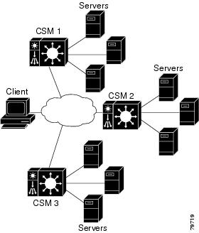
In this configuration illustration, the following apply to the configuration task and example:
•![]() CSM 1 does both GSLB and SLB, while CSM 2 and CSM 3 only do SLB.
CSM 1 does both GSLB and SLB, while CSM 2 and CSM 3 only do SLB.
•![]() CSM 1 has both a virtual server for SLB where the real servers in the serverfarm are the IP addresses of the local servers and a virtual server for GSLB.
CSM 1 has both a virtual server for SLB where the real servers in the serverfarm are the IP addresses of the local servers and a virtual server for GSLB.
•![]() The DNS policy uses a primary serverfarm where one of the real servers is local and the other two real servers are virtual servers configured on CSM 2 and CSM 3, respectively.
The DNS policy uses a primary serverfarm where one of the real servers is local and the other two real servers are virtual servers configured on CSM 2 and CSM 3, respectively.
•![]() Probes should be added for both the remote locations and the local real and virtual server.
Probes should be added for both the remote locations and the local real and virtual server.
•![]() DNS requests sent to a CSM 1 management IP address (a CSM 1 VLAN address or alias IP) will receive as a response one of the three real server IPs configured in the serverfarm GSLBFARM.
DNS requests sent to a CSM 1 management IP address (a CSM 1 VLAN address or alias IP) will receive as a response one of the three real server IPs configured in the serverfarm GSLBFARM.
To configure GSLB, perform these tasks:
This example shows how to configure GSLB:
On CSM1:
Router(config-module-csm)#serverfarm WEBFARM
Router(config-slb-sfarm)#predictor round-robin
Router(config-slb-sfarm)#real 3.5.5.5
Router(config-slb-real)#inservice
Router(config-slb-sfarm)#real 3.5.5.6
Router(config-slb-real)#inservice
Router(config-slb-real)#exit
Router(config-slb-sfarm)#exit
Router(config-module-csm)#vserver WEB
Router(config-slb-vserver)#virtual 10.10.10.10 tcp www
Router(config-slb-vserver)#serverfarm WEBFARM
Router(config-slb-vserver)#inservice
Router(config-module-csm)#serverfarm GSLBSERVERFARM dns-vip
Router(config-slb-sfarm)#predictor round-robine
Router(config-slb-sfarm)#real 10.10.10.10
Router(config-slb-real)#inservice
Router(config-slb-real)#exit
Router(config-slb-sfarm)#real 20.20.20.20
Router(config-slb-real)#inservice
Router(config-slb-real)#exit
Router(config-slb-sfarm)#real 30.30.30.30
Router(config-slb-real)#inservice
Router(config-slb-real)#exit
Router(config-module-csm)#map MAP1 dns
Router(config-dns-map)#match protocol dns domain foobar.com
Router(config-dns-map)#exit
Router(config-module-csm)#policy DNSPOLICY dns
Router(config-slb-policy)#dns map MAP1
Router(config-slb-policy)#serverfarm primary GSLBSERVERFARM ttl 20 responses 1
Router(config-slb-policy)#exit
Router(config-module-csm)#vserver DNSVSERVER dns
Router(config-slb-vserver)#dns-policy DNSPOLICY
Router(config-slb-vserver)#inservice
On CSM 2:
Router(config-module-csm)#serverfarm WEBFARM
Router(config-slb-sfarm)#predictor round-robin
Router(config-slb-sfarm)#real 4.5.5.5
Router(config-slb-real)#inservice
Router(config-slb-sfarm)#real 4.5.5.6
Router(config-slb-real)#inservice
Router(config-slb-real)#exit
Router(config-slb-sfarm)#exit
Router(config-module-csm)#vserver WEB
Router(config-slb-vserver)#virtual 20.20.20.20 tcp www
Router(config-slb-vserver)#serverfarm WEBFARM
Router(config-slb-vserver)#inservice
On CSM 3:
Router(config-module-csm)#serverfarm WEBFARM
Router(config-slb-sfarm)#predictor round-robin
Router(config-slb-sfarm)#real 5.5.5.5
Router(config-slb-real)#inservice
Router(config-slb-sfarm)#real 5.5.5.6
Router(config-slb-real)#inservice
Router(config-slb-real)#exit
Router(config-slb-sfarm)#exit
Router(config-module-csm)#vserver WEB
Router(config-slb-vserver)#virtual 30.30.30.30 tcp www
Router(config-slb-vserver)#serverfarm WEBFARM
Router(config-slb-vserver)#inservice
Configuring TCL Scripts
The CSM now enables you to upload and execute TCL (Toolkit Command Language) scripts on the CSM. TCL scripts allow you to write customized TCL scripts to develop customized health probes or standalone tasks. The TCL interpreter code in CSM is based on Release 8.0 of the standard TCL distribution. You can create a script to configure health probes (see "Configuring Scripts for Health Monitoring Probes" section) or to perform tasks on the CSM that are not part of a health probe. The CSM periodically executes the scripts at user configurable intervals.
Before CSM Release 3.1(1a), configuring a health probe for a protocol that was lacking in the basic health monitoring code was not possible. Now, you can write probes to customize the CSM for your specific application. TCL is a widely used scripting language within the networking community. It also has a huge libraries of scripts developed that can easily found from various sites.
The CSM currently supports two script modes.
•![]() Health-monitoring Script Mode—These scripts must be written using some simple rules. The execution of these scripts is controlled by Health-Monitoring module.
Health-monitoring Script Mode—These scripts must be written using some simple rules. The execution of these scripts is controlled by Health-Monitoring module.
•![]() Standalone Script Mode—These scripts can be considered as TCL scripts that you may download from the web. You control the execution of these scripts through the CSM configuration.
Standalone Script Mode—These scripts can be considered as TCL scripts that you may download from the web. You control the execution of these scripts through the CSM configuration.
For your convenience, sample scripts are available to support the TCL (Toolkit Command Language) feature. Other custom scripts will work, but these sample scripts are supported by Cisco TAC. The file with sample scripts is located at this URL:
http://www.cisco.com/cgi-bin/tablebuild.pl/cat6000-intellother
The file containing the scripts is named: c6slb-script.3-1-1a.tcl.
Loading Scripts
Scripts are loaded onto the CSM through script files. A script file may contain zero, one, or more scripts. Each script requires 128K bytes of stack space. Since there can be a maximum of 50 health scripts, the maximum stack space for script probes is 6.4 MB. Standalone scripts may also be running, which would consume more stack space.
Scripts can be loaded from a TFTP server, bootflash, slot0, and other storage devices using the script file [file-url] command.
This example shows how to load a script:
Router(config)# module csm 4
Router(config-module-csm)# script file tftp://192.168.1.1/httpProbe.test
The script name is either the filename of the script or a special name encoded within the script file. Each script file may contain a number scripts in the same file. To run the script or create a health probe using that script, you must refer to the script name, not the script file from which the script was loaded.
In order to identify each relevant script, each script must start with a line:
#!name = script_name
This example shows a master script file in which the scripts are bundled:
#!name = SCRIPT1
puts "this is script1"
!name = SCRIPT2
puts "this is script2"
This example shows how to find the scripts available in a master script file:
Router(config)#configure terminal
Router(config-t)# module csm 4
Router(config-module-csm)# script file tftp://192.168.1.1/script.master
Router(config-module-csm)# end
This example shows three scripts available from the script.master file:
Router(config)#show module csm 4 file tftp://192.168.1.1/script.master
RECURSIVE_TCL, file tftp://192.168.1.1/script.master
size = 304, load time = 03:49:36 UTC 03/26/93
ECHO_TCL, file tftp://192.168.1.1/script.master
size = 228, load time = 03:49:36 UTC 03/26/93
HTTP_PROBE, file tftp://192.168.1.1/script.master
size = 920, load time = 03:49:36 UTC 03/26/93
To show the contents of a loaded script file use this command:
Router(config)#show module csm slot script full_file_URL code
One major difference between a script task and a script probe is that the execution of a health script is scheduled by the health monitoring CSM module. These conditions apply:
•![]() A script can be modified while a script probe is active. The changes are picked up automatically in the next script execution. The same is true for command line arguments.
A script can be modified while a script probe is active. The changes are picked up automatically in the next script execution. The same is true for command line arguments.
•![]() During probe configuration, a particular script is attached to the probe. If the script is unavailable at that time, the probe executes with a NULL script. If this situation occurs, a warning flag is generated. However, when the script is loaded again, the binding between the probe object and the script does not run automatically. You must use the no script and script commands again to do the binding.
During probe configuration, a particular script is attached to the probe. If the script is unavailable at that time, the probe executes with a NULL script. If this situation occurs, a warning flag is generated. However, when the script is loaded again, the binding between the probe object and the script does not run automatically. You must use the no script and script commands again to do the binding.
•![]() Once a script is loaded it remains in the system. There is no way to remove a script. You can modify a script by changing a script and then by using the no script file and script file commands again.
Once a script is loaded it remains in the system. There is no way to remove a script. You can modify a script by changing a script and then by using the no script file and script file commands again.
•![]() Each script is always identified by its unique name. If two or more scripts have identical names, the last loaded script is used by the CSM. When there are duplicate script names, a warning message is generated by the CSM.
Each script is always identified by its unique name. If two or more scripts have identical names, the last loaded script is used by the CSM. When there are duplicate script names, a warning message is generated by the CSM.
Writing TCL Scripts
The CSM Release 3.1(1a) TCL script feature is based on the TCL 8.0 source distribution software. CSM TCL is modified to be the reentrant unlike standard the TCL library, allowing for concurrent TCL interpreter execution. The CSM TCL library does not support any standard TCL file I/O command, such as file, fcopy, and others. Table 5-2 lists the TCL commands that are supported by CSM.
Writing Health Scripts
After you configure each interval of time, an internal CSM scheduler schedules the health scripts. Write the script as if the intent is to perform only one probe. You must declare the result of the probe using the exit command.
A health script typically performs these actions:
•![]() Opens a socket to an IP address.
Opens a socket to an IP address.
•![]() Sends one or more requests.
Sends one or more requests.
•![]() Reads the responses.
Reads the responses.
•![]() Analyzes the responses.
Analyzes the responses.
•![]() Closes the socket.
Closes the socket.
•![]() Exits the script by using exit 5000 (success) or exit 5001 for failure.
Exits the script by using exit 5000 (success) or exit 5001 for failure.
This example shows how to probe an HTTP server using a health script:
Router(config)#!name = HTTP_TEST
# get the IP address of the real server from a predefined global array csm_env
set ip $csm_env(realIP)
set port 80
set url "GET /index.html HTTP/1.0\n\n"
# Open a socket to the server. This creates a TCP connection to the real server
set sock [socket $ip $port]
fconfigure $sock -buffering none -eofchar {}
# Send the get request as defined
puts -nonewline $sock $url;
# Wait for the response from the server and read that in variable line
set line [ read $sock ]
# Parse the response
if { [ regexp "HTTP/1.. (\[0-9\]+) " $line match status ] } {
puts "real $ip server response : $status"
}
# Close the socket. Application must close the socket once the
# is over. This allows other applications and tcl scripts to make
# a good use of socket resource. Health monitoring is allowed to open
# only 200 sockets simultaneously.
close $sock
# decide the exit code to return to control module.
# If the status code is OK then script MUST do exit 5000
# to signal successful completion of a script probe.
# In this example any other status code means failure.
# User must do exit 5001 when a probe has failed.
if { $status == 200 } {
exit 5000
} else {
exit 5001
}
Exit Codes
The CSM uses exit codes to signify various internal conditions. The exit code information can help you troubleshoot your scripts if they do not operate correctly. You can only use the exit 5000 and exit 5001 exit codes.
The TCL script may stop operating for these reasons:
•![]() Syntax errors—where there is no change in the state of the suspected improper syntax. The syntax error is a stored script control object and can be viewed using the sh mod csm X tech script command. A suspect will be denied.
Syntax errors—where there is no change in the state of the suspected improper syntax. The syntax error is a stored script control object and can be viewed using the sh mod csm X tech script command. A suspect will be denied.
•![]() A script hang—caused by an infinite loop or caused when the script attempts to connect to an invalid IP address. Each script must complete its task within the configured time interval. If the script does not complete its task, then the script controller terminates the script and the suspect will be FAILED implicitly.
A script hang—caused by an infinite loop or caused when the script attempts to connect to an invalid IP address. Each script must complete its task within the configured time interval. If the script does not complete its task, then the script controller terminates the script and the suspect will be FAILED implicitly.
•![]() Error conditions—for example, a connection timeout or a peer refused connection is also treated as an implicit FAILURE.
Error conditions—for example, a connection timeout or a peer refused connection is also treated as an implicit FAILURE.
Table 5-3 shows all exit codes used in the CSM.
This example shows how to use the EXIT_MSG variable to track script exit points to detect why a script is not working:
set EXIT_MSG "opening socket"
set s [socket 10.2.0.12 80]
set EXIT_MSG "writing to socket"
puts -nonewline $sock $url
Use the show module csm slot tech script command to check the EXIT_MSG.
Use the errorInfo and errorCode variables that are automatically set by the TCL core to determine why an error occurred. TCL stores internal error information using the errorInfo variable whenever a script task is aborted. Syntax errors for example, panic etc. will set these variables with the appropriate information which you can use to troubleshoot the error.
Environment Variable
Health scripts have access to many configured items through a predefined TCL array. The most common use of this array is to find the current real server IP addresses of the suspect during any particular launch of the script. Table 5-4 lists the members of the csm_env array.
You can use the new probe probe-name> script command for creating a script probe in Cisco IOS. This command enters a probe submode that is similar to the existing CSM health probe sub-modes (such as HTTP, TCP, DNS, SMTP, etc.). The probe script submode contains the existing probe submode commands failed, interval, open, receive, and retries.
A new command script script-name was added to the probe script submode. This command can take up to 5 arguments that are passed to the script when it is run as part of the health probe function.
You can also use the corresponding show module csm <slot> probe script [name <probe-name>] [code] command. Refer to the "Command Reference" in Appendix A for details about these commands.
System Resource Usage
Vxworks has 255 file descriptors that are divided across all applications, for example, standard input and output, and any socket connections (to or from). When developing standalone scripts, you must be extremely careful when opening a socket. We recommend that you close a socket as soon as the operation is complete because you may run out of resources. The health monitoring module controls the number of open sockets by way of controlling the number of actively running scripts. There is no such control for standalone scripts.
Memory, although a consideration, is not a big limiting factor since the module generally has enough memory available. Each script uses a 128K stack, and the rest of the memory is allocated at runtime by the script.
The script tasks are given the lowest priority in the system such that the real time characteristics of the system remain more or less the same while executing scripts. Unfortunately, scripts having low priority also means that if the system is busy doing non TCL operations, all TCL threads may take longer to complete. This situation may lead to some health scripts being terminated and the unfinished threads marked failed. To prevent scripts being failed, all script probes should have a retry value of 2 or more. You may want to use native CSM probes (for example, HTTP, DNS, etc.) whenever possible. The scripted health probes should be used to support non-supported applications. The purpose is to provide features, not speed.
TCL supports both synchronous and asynchronous socket commands. Asynchronous socket commands return immediately without waiting for true connections. The internal implementation of the asynchronous script version involves a much more complicated code path with many more system calls per each such command. This condition generally slows down the system by holding some critical resources. We do not recommend using the asynchronous socket for scripted probes unless this is a definite requirement. However, you may use this command in a standalone system.
Writing Standalone Scripts
There are no special considerations for developing a standalone script.
Running TCL Scripts
Once a script file has been loaded, the scripts in that file exist in the CSM independent of the file from which that script was loaded. If a script file is subsequently modified, use the script file command to reload the script file and enable the changes on the CSM. (See the "script file" section.)
The no script file command removes the script file command from the running configuration. This command does not unload the scripts in that file and does not affect scripts that are currently running on the CSM. You cannot unload scripts that have been loaded. If a loaded script is no longer needed, it is not necessary to remove it; however, do not use it.
In addition to displaying general script information, the code version of the script command (see the "show module csm script" section) displays the actual code within the script.
One of the key requirements of porting the TCL standard distribution to the CSM is to modify this base distribution to provide for re-entrance. With a re-entrant TCL library, it is possible for multiple vxWorks threads to be executing TCL interpreters simultaneously. This facility allows many health scripts and other custom scripts to simultaneously execute in multiple TCL interpreters.
Running Probe Scripts
A probe script indicates the relative health and availability of a real server using the exit code of the script. By calling exit (5000), a script indicates the server successfully responded to the probe. Calling exit (5001) indicates the server did not respond correctly to the health probe.
Whenever a script probe is executed on the CSM, a special array called csm_env is passed to the script. This array holds important parameters that may be used by the script. Refer to Table 5-4 for a list of the array parameters.
To run a probe script, you must configure a script probe type and then associate a script name with the probe object (see the "probe script" section) as follows:
Router(config)#probe probe_name script
Router(config-probe-script)#script script_name [command line arguments]
To run a probe script, use this configuration:
Router(config)# ip slb script file tftp://192.168.10.102/csmScripts
Router(config)#probe ECHOSCRIPT script
Router(config-probe-script)#script echoProbe.tcl
Router(config-probe-script)#interval 10
Router(config-probe-script)#retries 1
Router(config-probe-script)#failed 30
Running Standalone TCL Scripts
The script file command may be stored in the startup configuration so that it will run when the CSM boots. The script continues to run while the CSM is operating.
To run a TCL script when booting the module, perform this task:
This example shows how to run a script as a task when booting the CSM:
Router(config-module-csm)#configure terminal
Router(config-module-csm)#module csm 4
Router(config-module-csm)#script file tftp://192.168.1.1/httpProbe.test
One of the arguments of the script task command is script index, which is an integer between 1 and 100. The script index is used to halt a specific executing script task instance using the no script task command.
To run a standalone TCL script, perform this task:
This example shows how to run a script as a task when booting the CSM:
Router(config-module-csm)#confure terminal
Router(config-module-csm)#module csm 4
Router(config-module-csm)#script task 1 RECURSIVE_TCL
As shown in the examples, use the show module csm slot script task [index script-index] [detail] and the show module csm slot script [name script-name] [code] commands to display information about a specific running script.
Halting TCL Scripts
Use the no script task id command to destroy the script task. The task object will be available for postmortem and status even after the task finishes executing. If you need to rerun the same script again, you must do the following:
•![]() Use a different task ID.
Use a different task ID.
•![]() Run the no script task id command first, and then retype the command for that script.
Run the no script task id command first, and then retype the command for that script.
Note ![]() If you decide to modify the script or the command line arguments while a script task command is running, you must stop the task using the no script task command and then rerun the task.
If you decide to modify the script or the command line arguments while a script task command is running, you must stop the task using the no script task command and then rerun the task.
Configuring the XML Interface
In previous releases, the only method available for configuration of the CSM was the IOS command line interface. With XML, you can programmatically configure the CSM.
These considerations apply to XML for the CSM:
•![]() Up to 5 concurrent client connections are allowed.
Up to 5 concurrent client connections are allowed.
•![]() The XML configuration is independent of the current ip slb mode, with the following exception: the <csm_module slot='x' sense='no'> does have the desired effect and generates an XML error. Only CSM 2.2 features are supported by the Document Type Definition (DTD).
The XML configuration is independent of the current ip slb mode, with the following exception: the <csm_module slot='x' sense='no'> does have the desired effect and generates an XML error. Only CSM 2.2 features are supported by the Document Type Definition (DTD).
•![]() Pipelined HTTP posts are not supported.
Pipelined HTTP posts are not supported.
•![]() 30 second timeout for all client communication.
30 second timeout for all client communication.
•![]() Bad client credentials cause a message to be syslogged to IOS.
Bad client credentials cause a message to be syslogged to IOS.
•![]() A single CSM can act as proxy for other CSM configuration, by specifying a different slot attribute.
A single CSM can act as proxy for other CSM configuration, by specifying a different slot attribute.
When you enable this feature, a network management device may connect to the CSM and push new configurations to the device. The network management device pushes configuration commands to the CSM using the standard HTTP protocol. The new configuration is applied by sending an XML document to the CSM in the data portion of an HTTP POST.
This example shows an HTTP conversation:
******** Client **************
POST /xml-config HTTP/1.1
Authorization: Basic VTpQ
Content-Length: 95
<?xml version="1.0"?>
<config><csm_module slot="4"><vserver name="FOO"/></csm_module></config>
******** Server **************
HTTP/1.1 200 OK
Content-Length: 21
<?xml version="1.0"?>
******** Client **************
POST /xml-config HTTP/1.1
Content-Length: 95
<?xml version="1.0"?>
<config><csm_module slot="4"><vserver name="FOO"/></csm_module></config>
******** Server **************
HTTP/1.1 401 Unauthorized
Connection: close
WWW-Authenticate: Basic realm=/xml-config
The following HTTP return codes are all supported:
The following HTTP headers are supported:
•![]() Content-Length (non-zero value required for all POSTs)
Content-Length (non-zero value required for all POSTs)
•![]() Connection (close value indicates that request should not be persistent)
Connection (close value indicates that request should not be persistent)
•![]() WWW-Authenticate (sent to client when credentials are required and missing)
WWW-Authenticate (sent to client when credentials are required and missing)
•![]() Authorization (sent from client to specify Basic credentials in base64 encoding)
Authorization (sent from client to specify Basic credentials in base64 encoding)
For the XML feature to operate, the network management system must connect to a CSM IP address, not a switch interface IP address.
Because the master copy of the configuration must be stored in Cisco IOS, as it is with the command line interface, when XML configuration requests are received by the CSM, these requests must be sent up to the supervisor.
Note ![]() XML configuration allows a single CSM to act as proxy for all the CSMs in the same switch chassis. For example, an XML page with configuration for one CSM may be successfully posted through a different CSM in the same switch chassis.
XML configuration allows a single CSM to act as proxy for all the CSMs in the same switch chassis. For example, an XML page with configuration for one CSM may be successfully posted through a different CSM in the same switch chassis.
The Document Type Description (DTD), now publicly available, is the basis for XML configuration documents you create. (See "CSM XML Document Type Definition.") The XML documents are sent directly to the CSM in HTTP POST requests. To use XML, a minimum configuration must be created on the CSM in advance, using the Cisco IOS command line interface. Refer "Command Reference" for information on the xml-config command.
The response is an XML document mirroring the request, with troublesome elements flagged with child error elements, and with an error code and error string. You can specify which types of errors should be ignored by using an attribute of the root element in the XML document.
There will be an addition to the Cisco IOS command line interface for enabling XML configuration capabilities for a particular CSM interface. Along with the ability to enable and disable and the TCP port, security options for client access lists and HTTP authentication are supported.
To configure XML on the CSM, perform this task:
This example shows how to run configure XML on the CSM:
Router(config-module-csm)#configure terminal
Router(config-module-csm)#module csm 4
Router(config-module-csm)#xml-config
Router(config-slb-xml)#port 23
Router(config-slb-xml)#vlan 200
Router(config-slb-xml)#client-group 60
Router(config-slb-xml)#credentials eric @#$#%%@
Router#show module csm 4 xml stats
When an untolerated XML error occurs, the HTTP response contains a 200 code. The portion of the original XML document with the error is returned with an error element that contains the error type and description.
This example shows an error response to a condition where a virtual server name is missing:
<?xml version="1.0"?>
<config>
<csm_module slot="4">
<vserver>
<error code="0x20">Missing attribute name in element
vserver</error>
</vserver>
</csm_module>
</config>
The error codes returned also correspond to the bits of the error tolerance attribute of the configuration element. Returned XML error codes are:
XML_ERR_INTERNAL = 0x0001,
XML_ERR_COMM_FAILURE = 0x0002,
XML_ERR_WELLFORMEDNESS = 0x0004,
XML_ERR_ATTR_UNRECOGNIZED = 0x0008,
XML_ERR_ATTR_INVALID = 0x0010,
XML_ERR_ATTR_MISSING = 0x0020,
XML_ERR_ELEM_UNRECOGNIZED = 0x0040,
XML_ERR_ELEM_INVALID = 0x0080,
XML_ERR_ELEM_MISSING = 0x0100,
XML_ERR_ELEM_CONTEXT = 0x0200,
XML_ERR_IOS_PARSER = 0x0400,
XML_ERR_IOS_MODULE_IN_USE = 0x0800,
XML_ERR_IOS_WRONG_MODULE = 0x1000,
XML_ERR_IOS_CONFIG = 0x2000
The default error_tolerance value is 0x48, which corresponds to ignoring unrecognized attributes and elements.
 Feedback