- Title and copyright: T1/E1 Digital Voice Port Adapter Installation and Configuration
- Preface: T1/E1 Digital Voice Port Adapter Installation and Configuration
- Overview: T1/E1 Digital Voice Port Adapter Installation and Configuration
- Preparing to Install the T1/E1 Digital Voice Port Adapter
- Removing and Installing the T1/E1 Digital Voice Port Adapter
- Configuring the T1/E1 Digital Voice Port Adapter
Overview
This chapter describes the PA-VXA, PA-VXB, and PA-VXC port adapters and contains the following sections:
•![]() LEDs
LEDs
•![]() Cables, Connectors, and Pinouts
Cables, Connectors, and Pinouts
•![]() Port Adapter Slot Locations on the Supported Platforms
Port Adapter Slot Locations on the Supported Platforms
•![]() Identifying Interface Addresses
Identifying Interface Addresses
Port Adapter Overview
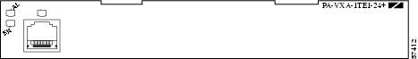
The PA-VXA-1TE1-24+(=) (see Figure 1-1) is a single port T1/E1 voice port adapter with seven active digital signal processors (DSPs). This PA-VXA can support up to 28 simultaneous medium-complexity codec (G.729a, G.726, or G.711) voice channels—enough channels to support a single T1 or E1 line.
Figure 1-1 PA-VXA-1TE1-24+ Port Adapter
The PA-VXA-1TE1-30+(=) (see Figure 1-2) is a single port T1/E1 voice port adapter with eight active DSPs. This PA-VXA can support up to 32 simultaneous medium-complexity codec (G.729a, G.726, or G.711) voice channels—enough channels to support a single T1 or E1 line.
Figure 1-2 PA-VXA-1TE1-30+ Port Adapter

The PA-VXAs are single-width port adapters with one universal port that is configurable for either a T1 or E1 connection. Using a PA-VXA packet voice port adapter, Cisco 7200 series routers, Cisco 7200 VXR routers, and Cisco 7500 series routers can become dedicated packet voice hubs or packet voice gateways that connect to both private branch exchanges (PBXs) and the Public Switched Telephone Network (PSTN). The result is that packet voice and packet fax calls can be placed over the wide-area network (WAN) and sent through the gateway into a traditional circuit-switched voice infrastructure.
The PA-VXB and the PA-VXC (see Figure 1-3 and Figure 1-4) are multichannel packet voice port adapters that allow Cisco 7200 series routers, Cisco 7200 VXR routers, Cisco 7301 routers, Cisco 7401ASR routers, and Cisco 7500 series routers to become dedicated packet voice hubs or packet voice gateways that connect to both private branch exchanges (PBXs) and the Public Switched Telephone Network (PSTN). With this technology, packet voice and packet fax calls can be placed over the wide-area network (WAN) and sent through the gateway into the traditional circuit-switched voice infrastructure.
Figure 1-3 PA-VXB-2TE1 Port Adapter
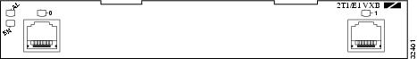
Figure 1-4 PA-VXC-2TE1 Port Adapter
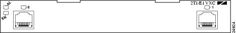
The PA-VXB and PA-VXC are single-width port adapters with two universal ports that are configurable for either T1 or E1 connections. The PA-VXB contains 12 high-performance digital signal processors (DSPs) that support up to 48 medium-complexity or 24 high-complexity channels of compressed voice. The PA-VXC contains 30 high-performance DSPs that support up to 120 medium-complexity or 60 high-complexity channels of compressed voice.
In Voice over IP, the DSP segments the voice signal into frames, which are then coupled in groups of two and stored in voice packets. These voice packets are transported using IP in compliance with ITU-T specification H.323. Because Voice over IP is a delay-sensitive application, you must have a well-engineered end-to-end network to use it successfully. Fine-tuning your network to adequately support Voice over IP involves a series of protocols and features geared toward quality of service (QoS). Traffic shaping considerations must be taken into account to ensure the reliability of the voice connection.
Features
The PA-VXA, PA-VXB, and PA-VXC have the following features:
•![]() Universal ports—One interface port (PA-VXA) or two interface ports (PA-VXB and PA-VXC) per port adapter are configurable as either T1 (with integrated CSU/DSU) or E1 (with integrated G.703/G.704 120-ohm interface). Additionally, a port may be configured on a per-DS0 basis for voice termination, time-division multiplexing (TDM) pass-through (cross-connect), or packet data.
Universal ports—One interface port (PA-VXA) or two interface ports (PA-VXB and PA-VXC) per port adapter are configurable as either T1 (with integrated CSU/DSU) or E1 (with integrated G.703/G.704 120-ohm interface). Additionally, a port may be configured on a per-DS0 basis for voice termination, time-division multiplexing (TDM) pass-through (cross-connect), or packet data.
•![]() High-density digital signal processor (DSP) technology—Full support exists for low-bit-rate voice compression (down to 5.3 kbps) on all T1/E1 port channels.
High-density digital signal processor (DSP) technology—Full support exists for low-bit-rate voice compression (down to 5.3 kbps) on all T1/E1 port channels.
•![]() Multiservice Interchange (MIX) support—Voice channels can be TDM-switched between port adapter slots in the Cisco 7200 VXR chassis. This allows DSP resources to be shared between port adapters in the same chassis or for port-to-port DS0 cross-connect between port adapter slots.
Multiservice Interchange (MIX) support—Voice channels can be TDM-switched between port adapter slots in the Cisco 7200 VXR chassis. This allows DSP resources to be shared between port adapters in the same chassis or for port-to-port DS0 cross-connect between port adapter slots.
•![]() DS0 drop and insert—Flexible TDM cross-connect capability between ports and the MIX bus is available.
DS0 drop and insert—Flexible TDM cross-connect capability between ports and the MIX bus is available.
•![]() VoIP and VoFR termination—Full VoIP and Voice over Frame Relay (VoFR) gateway functionality for mixed environments is available.
VoIP and VoFR termination—Full VoIP and Voice over Frame Relay (VoFR) gateway functionality for mixed environments is available.
•![]() Full-featured DSP firmware—Support exists for eight standard-compression algorithms plus echo cancellation, full dual tone multifrequency (DTMF)/MF tone detection and generation, and dial-pulse generation.
Full-featured DSP firmware—Support exists for eight standard-compression algorithms plus echo cancellation, full dual tone multifrequency (DTMF)/MF tone detection and generation, and dial-pulse generation.
•![]() Silence suppression—To conserve network bandwidth, voice activity detection (VAD) prevents sending data when no voice is present. Comfort-noise generation prevents uncomfortable dead silence on the receiving end.
Silence suppression—To conserve network bandwidth, voice activity detection (VAD) prevents sending data when no voice is present. Comfort-noise generation prevents uncomfortable dead silence on the receiving end.
•![]() Multiple clocking options—Ports can be clocked internally from the network, or the network clock from one port can be sent to the other port on the card or to other cards across the MIX bus in the VXR chassis.
Multiple clocking options—Ports can be clocked internally from the network, or the network clock from one port can be sent to the other port on the card or to other cards across the MIX bus in the VXR chassis.
•![]() Flexible signaling support—Channel-associated signaling (CAS) and common channel signaling (CCS) support is available for both E1 and T1 applications in H.323 environments.
Flexible signaling support—Channel-associated signaling (CAS) and common channel signaling (CCS) support is available for both E1 and T1 applications in H.323 environments.
DSP features:
•![]() Coders/decoders (codecs):
Coders/decoders (codecs):
G.711 (a-law/u-law), G.729/G.729.a (with b variant), G.723.1, G.728, G.726
•![]() Fax relay through T.30 support:
Fax relay through T.30 support:
V.17, V.29, V.27
•![]() Echo cancellation—32 milliseconds meeting G.165
Echo cancellation—32 milliseconds meeting G.165
•![]() DTMF/R2/MF/SF/CP tone detection and generation
DTMF/R2/MF/SF/CP tone detection and generation
•![]() Dial-pulse detection and generation
Dial-pulse detection and generation
•![]() Energy-based voice activity detection (VAD) and codec-specific VAD
Energy-based voice activity detection (VAD) and codec-specific VAD
•![]() Comfort noise generator
Comfort noise generator
Signaling supported for H.323 environments:
•![]() H.323 V.2 support
H.323 V.2 support
•![]() E1 CAS, T1 CAS (robbed-bit signaling)
E1 CAS, T1 CAS (robbed-bit signaling)
•![]() CCS signaling—E1 and T1 PRI (user and network side), Q.SIG
CCS signaling—E1 and T1 PRI (user and network side), Q.SIG
•![]() R2 signaling
R2 signaling
Port configured as T1 features:
•![]() DS1 100-ohm interfaces with RJ-45 connectors
DS1 100-ohm interfaces with RJ-45 connectors
•![]() D4 super frame (SF) and extended super frame (ESF) framing
D4 super frame (SF) and extended super frame (ESF) framing
•![]() Alternate mark inversion (AMI) or binary 8-zero substitution (B8ZS) line encoding
Alternate mark inversion (AMI) or binary 8-zero substitution (B8ZS) line encoding
•![]() Full Facility Data Link (FDL) support and FDL performance monitoring per ANSI T1.403 or AT&T TR 54016
Full Facility Data Link (FDL) support and FDL performance monitoring per ANSI T1.403 or AT&T TR 54016
•![]() Selectable DSX-1 cable length in increments from 0 to 655 feet (0 to 79.64 meters)
Selectable DSX-1 cable length in increments from 0 to 655 feet (0 to 79.64 meters)
•![]() Selectable DS1 CSU line build-out—0, -7.5, -15, or -22.5 dB
Selectable DS1 CSU line build-out—0, -7.5, -15, or -22.5 dB
•![]() Selectable DS1 CSU receiver gain—26 or 36 dB
Selectable DS1 CSU receiver gain—26 or 36 dB
•![]() DS1 line protection per UL1459/1950, FCC part 68
DS1 line protection per UL1459/1950, FCC part 68
•![]() Full support for DSX-1 Management Information Base (MIB), RFC 1406, including alarm detection and reporting
Full support for DSX-1 Management Information Base (MIB), RFC 1406, including alarm detection and reporting
•![]() DSX-1 MIB remote access supported
DSX-1 MIB remote access supported
Port configured as E1 features:
•![]() E1 120-ohm (G.703) with RJ-48C connectors
E1 120-ohm (G.703) with RJ-48C connectors
•![]() Software-configurable E1 national bits
Software-configurable E1 national bits
•![]() Binary 3-zero substitution (B3ZS) encoding
Binary 3-zero substitution (B3ZS) encoding
•![]() Full support for E1 MIB, RFC 1406, including alarm detection and reporting
Full support for E1 MIB, RFC 1406, including alarm detection and reporting
Full bit-error-rate testing capabilities on each E1/T1:
•![]() Programmable pseudorandom pattern up to 24 bits in length, including 211-1, 215-1, 220-1, 220-1 QRSS, 233-1, all zeros, all ones, and alternating ones and zeros
Programmable pseudorandom pattern up to 24 bits in length, including 211-1, 215-1, 220-1, 220-1 QRSS, 233-1, all zeros, all ones, and alternating ones and zeros
•![]() 32-bit-error count registers
32-bit-error count registers
Supported loopbacks:
•![]() Line loopback—T1/E1 stream is looped back at the line interface unit (LIU) toward the network.
Line loopback—T1/E1 stream is looped back at the line interface unit (LIU) toward the network.
•![]() Payload loopback—T1/E1 data stream is looped back at the framer toward the network.
Payload loopback—T1/E1 data stream is looped back at the framer toward the network.
•![]() Diagnostic local loopback—T1/E1 data stream is looped back at the framer toward the system.
Diagnostic local loopback—T1/E1 data stream is looped back at the framer toward the system.
•![]() Remote loopback—T1 stream is looped back at the LIU toward the network upon request from the far-end through the FDL command.
Remote loopback—T1 stream is looped back at the LIU toward the network upon request from the far-end through the FDL command.
LEDs
As shown in Figure 1-1 and Figure 1-2, the PA-VXAs have three LEDs on the faceplates; a green enabled LED, a bicolor alarm LED, and a bicolor port status LED. Table 1-1 lists the colors and functions of the LEDS.
As shown in Figure 1-3 and Figure 1-4, the PA-VXB and PA-VXC port adapters have four LEDs on the faceplate: a green enabled LED, a bicolor alarm LED, and two bicolor port status LEDs, one for each port. Table 1-1 lists the colors and functions of the LEDs.
Cables, Connectors, and Pinouts
The T1/E1 interface receptacles on the PA-VXA, PA-VXB, and PA-VXC port adapters are for RJ-45 connectors for both T1 (100 ohm) and E1 (120 ohm).
After you properly connect a port to a line, it takes approximately 30 seconds for the Cisco IOS to report that the line is up.
Each connection supports T1(100-ohm) or E1(120-ohm) interfaces that meet T1.403 and ACCUNET TR62411 standards. The RJ-45 connection does not require an external transceiver. The DS1 ports are T1 interfaces that use foil twisted-pair cables.
Shielded cables (foil twisted-pair [FTP]) with 120-ohm impedance are required to comply with CE marking requirements.
Figure 1-5 shows the PA-VXA, PA-VXB, and PA-VXC port adapter interface cable connector. See the "Connecting Interface Cables" section for directions on connecting the cables to a PA-VXA, PA-VXB, or PA-VXC.
Figure 1-5 PA-VXA, PA-VXB, and PA-VXC Port Adapter Interface Connector
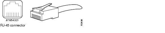
Table 1-2 lists the signal pinouts and descriptions for the RJ-45 connector.
|
|
|
|---|---|
1 |
RX tip |
2 |
RX ring |
3 |
No connection |
4 |
TX tip |
5 |
TX ring |
6 |
No connection |
7 |
No connection |
8 |
No connection |
Port Adapter Slot Locations on the Supported Platforms
This section discusses port adapter slot locations on the supported platforms. The illustrations that follow summarize slot location conventions on each platform:
•![]() Cisco 7200 Series and Cisco 7200 VXR Routers Slot Numbering
Cisco 7200 Series and Cisco 7200 VXR Routers Slot Numbering
•![]() Cisco 7301 Router Slot Numbering
Cisco 7301 Router Slot Numbering
•![]() Cisco 7401ASR Router Slot Numbering
Cisco 7401ASR Router Slot Numbering
Cisco 7200 Series and Cisco 7200 VXR Routers Slot Numbering
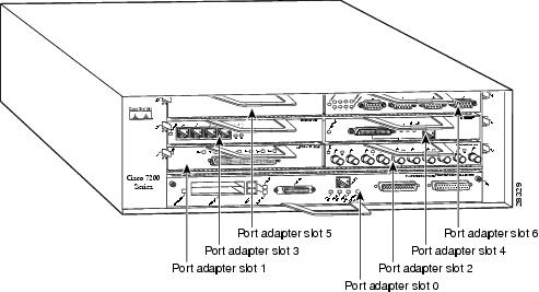
Figure 1-6 shows a Cisco 7206 with port adapters installed. In the Cisco 7206, port adapter slot 1 is in the lower left position, and port adapter slot 6 is in the upper right position. (The Cisco 7202 and Cisco 7204 are not shown; however, the PA-VXA, PA-VXB, and PA-VXC port adapters can be installed in any available port adapter slot. Slot 0 is always reserved for the Fast Ethernet port on the I/O controller—if present.)
Figure 1-6 Port Adapter Slots in the Cisco 7206
Cisco 7301 Router Slot Numbering
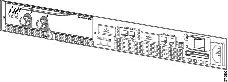
The Cisco 7301 router has one port adapter slot. See Figure 1-7.
Figure 1-7 Port Adpater Slot on the Cisco 7301 Router

Note ![]() The Cisco 7301 router is currently supported by the PA-VXB-2TE1+(=)
The Cisco 7301 router is currently supported by the PA-VXB-2TE1+(=)
and the PA-VXC-2TE1(=) port adapters only.
Cisco 7401ASR Router Slot Numbering
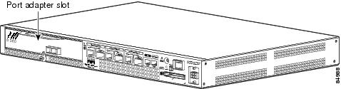
Figure 1-8 shows the front view of the Cisco 7401ASR router with a port adapter installed. There is only one port adapter slot in a Cisco 7401ASR router and it is port adapter slot 1.
Figure 1-8 Cisco 7401ASR Router with a Port Adapter Installed
Note ![]() The Cisco 7401ASR router is currently supported by the PA-VXB-2TE1+(=)
The Cisco 7401ASR router is currently supported by the PA-VXB-2TE1+(=)
and the PA-VXC-2TE1+(=) port adapters only.
VIP Slot Numbering
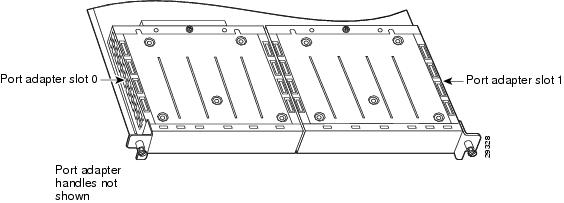
Figure 1-9 shows a partial view of a VIP motherboard with installed port adapters that would be used with a Cisco 7500 series router. With the motherboard oriented as shown in Figure 1-9, the left port adapter is in port adapter slot 0, and the right port adapter is in port adapter slot 1. The slots are always numbered 0 and 1.
Figure 1-9 VIP Motherboard with Two Port Adapters Installed—Horizontal Orientation
Note ![]() In the Cisco 7507, and Cisco 7513 chassis, the VIP motherboard is installed vertically. In the Cisco 7505 chassis, the VIP motherboard is installed horizontally as shown in Figure 1-10.
In the Cisco 7507, and Cisco 7513 chassis, the VIP motherboard is installed vertically. In the Cisco 7505 chassis, the VIP motherboard is installed horizontally as shown in Figure 1-10.
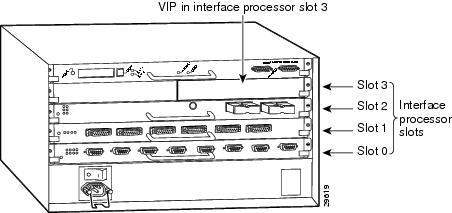
Interface processor slots are numbered as shown in Figure 1-10.
Figure 1-10 Interface Slot Numbers—Cisco 7505 Shown
Identifying Interface Addresses
This section describes how to identify interface addresses for the PA-VXA, PA-VXB, and PA-VXC port adapters in supported platforms. Interface addresses specify the actual physical location of each interface on a router or switch.
Interfaces on the PA-VXA, PA-VXB, and PA-VXC port adapters installed in a router maintain the same address regardless of whether other port adapters are installed or removed. However, when you move a port adapter to a different slot, the first number in the interface address changes to reflect the new port adapter slot number.
Note ![]() Interface ports are numbered from left to right starting with 0.
Interface ports are numbered from left to right starting with 0.
Table 1-3 explains how to identify interface addresses.
|
|
|
|
|
|---|---|---|---|
Cisco 7200 series and Cisco 7200 VXR routers |
Port-adapter-slot-number/interface-port-number |
Port adapter slot—1 through 6 (depends on the number of slots in the router)1 Interface port—0 or 1 |
1/0 |
Cisco 7301 routers2 |
Port-adapter-slot-number/interface-port-number |
Port adapter slot—always 1 Interface port—0 or 1 |
1/0 |
Cisco 7401ASR routers3 |
Port-adapter-slot-number/interface-port-number |
Port adapter slot—always 1 Interface port—0 or 1 |
1/0 |
VIP in Cisco 7500 series routers |
Interface-processor-slot-number/port-adapter-slot-number/interface-port-number |
Interface processor slot—0 through 12 (depends on the number of slots in the router) Port adapter slot—always 0 or 1 Interface port—0 or 1 |
3/0/0 |
1 Port adapter slot 0 is reserved for the Fast Ethernet port on the I/O controller (if present). 2 The Cisco 7301 router is currently supported by the PA-VXB-2TE1+(=) and the PA-VXC-2TE1(=) port adapters only. 3 The Cisco 7401ASR router is currently supported by the PA-VXB-2TE1+(=) and the PA-VXC-2TE1+(=) port adapters only. |
Cisco 7200 Series Routers Interface Addresses
This section describes how to identify the interface addresses used for the PA-VXA, PA-VXB, and PA-VXC port adapters in Cisco 7200 series and Cisco 7200 VXR routers. The interface address is composed of a two-part number in the format port-adapter-slot-number/interface-port-number. See Table 1-3 for the interface address format.
In Cisco 7200 series and Cisco 7200 VXR routers, port adapter slots are numbered from the lower left to the upper right, beginning with port adapter slot 1 and continuing through port adapter slot 2 for the Cisco 7202, slot 4 for the Cisco 7204 and Cisco 7204VXR, and slot 6 for the Cisco 7206 and Cisco 7206VXR. (Port adapter slot 0 is reserved for the optional Fast Ethernet port on the I/O controller—if present.)
Cisco 7301 Router Interface Addresses
This section describes how to identify the interface addresses used for the the PA-VXB-2TE1+(=) or the PA-VXC-2TE1(=) in a Cisco 7301 router. In the Cisco 7301 router, slot 1 is the port adapter slot you use for any of these two port adapters. (See Figure 1-7.) The interface address is composed of a two-part number in the format port-adapter-slot-number/interface-port-number. See Table 1-3 for the interface address format.
Note ![]() The Cisco 7301 router is currently supported by the PA-VXB-2TE1+(=)
The Cisco 7301 router is currently supported by the PA-VXB-2TE1+(=)
and the PA-VXC-2TE1(=) port adapters only.
Cisco 7401ASR Router Interface Addresses
This section describes how to identify the interface addresses used for the the PA-VXB-2TE1+(=) or the PA-VXC-2TE1+(=) in a Cisco 7401ASR router. In the Cisco 7401ASR router, slot 1 is the port adapter slot you use for any of these two port adapters. (See Figure 1-8.) The interface address is composed of a two-part number in the format port-adapter-slot-number/interface-port-number. See Table 1-3 for the interface address format.
Note ![]() The Cisco 7401ASR router is currently supported by the PA-VXB-2TE1+(=)
The Cisco 7401ASR router is currently supported by the PA-VXB-2TE1+(=)
and the PA-VXC-2TE1+(=) port adapters only.
Cisco 7500 Series Routers Interface Addresses
This section describes how to identify the interface addresses used for the PA-VXA, PA-VXB, and PA-VXC on a VIP in Cisco 7500 series routers.
Note ![]() Although the processor slots in the seven-slot Cisco 7507 and the thirteen-slot Cisco 7513 and Cisco 7576 are vertically oriented and those in the five-slot Cisco 7505 are horizontally oriented, all Cisco 7500 series routers use the same method for slot and port numbering.
Although the processor slots in the seven-slot Cisco 7507 and the thirteen-slot Cisco 7513 and Cisco 7576 are vertically oriented and those in the five-slot Cisco 7505 are horizontally oriented, all Cisco 7500 series routers use the same method for slot and port numbering.
The interface address is composed of a three-part number in the format interface-processor-slot-number/port-adapter-slot-number/interface-port-number. See Table 1-3 for the interface address format.
 Feedback