- Title and copyright: MIX-Multichannel T1/E1 Port Adapter Installation and Configuration
- Preface: MIX-Multichannel T1/E1 Port Adapter Installation and Configuration
- Overview: MIX-Multichannel T1/E1 Port Adapter Installation and Configuration
- Preparing to Install the MIX-Multichannel T1/E1 Port Adapter
- Removing and Installing the MIX-Multichannel T1/E1 Port Adapter
- Configuring the MIX-Multichannel T1/E1 Port Adapter
- Using the EXEC Command Interpreter
- Configuring the Interfaces
- Configuring Voice over IP
Configuring the PA-MCX
To continue your PA-MCX port adapter installation, you must configure the card type as either T1 or E1 and then configure the interfaces.
This chapter contains the following sections:
•![]() Using the EXEC Command Interpreter
Using the EXEC Command Interpreter
•![]() Configuring Voice over Frame Relay
Configuring Voice over Frame Relay
Using the EXEC Command Interpreter
You modify the configuration of your router through the software command interpreter called the EXEC (also called enable mode). You must enter the privileged level of the EXEC command interpreter with the enable command before you can use the configure command to configure a new interface or change the existing configuration of an interface. The system prompts you for a password if one has been set.
The system prompt for the privileged level ends with a pound sign (#) instead of an angle bracket (>). At the console terminal, use the following procedure to enter the privileged level:
Step 1 ![]() At the user-level EXEC prompt, enter the enable command. The EXEC prompts you for a privileged-level password as follows:
At the user-level EXEC prompt, enter the enable command. The EXEC prompts you for a privileged-level password as follows:
Router> enable
Password:
Step 2 ![]() Enter the password (the password is case sensitive). For security purposes, the password is not displayed.
Enter the password (the password is case sensitive). For security purposes, the password is not displayed.
When you enter the correct password, the system displays the privileged-level system prompt (#):
Router#
To configure the new interfaces, proceed to the "Configuring the Interfaces" section.
Configuring the Interfaces
The PA-MCX interfaces can be configured as data-only interfaces or as TDM cross-connects to a digital voice port adapter. After you verify that the new PA-MCX is installed correctly (the enabled LED goes on), use the privileged-level configure command to configure the new interfaces. Have the following information available:
•![]() Protocols you plan to route on each new interface
Protocols you plan to route on each new interface
•![]() IP addresses, if you plan to configure the interfaces for IP routing
IP addresses, if you plan to configure the interfaces for IP routing
•![]() Voice network plan
Voice network plan
•![]() Clock timing source you plan to use for each new interface and clock speeds for external timing
Clock timing source you plan to use for each new interface and clock speeds for external timing
If you installed a new PA-MCX or if you want to change the configuration of an existing interface, you must enter configuration mode to configure the new interfaces. If you replaced a PA-MCX that was previously configured, the system recognizes the new interfaces and brings each of them up in their existing configuration.
For a summary of the configuration options available and instructions for configuring interfaces on a PA-MCX, refer to the appropriate configuration publications listed in the "Related Documentation" section on page viii.
You execute configuration commands from the privileged level of the EXEC command interpreter, which usually requires password access. Contact your system administrator, if necessary, to obtain password access. (See the "Using the EXEC Command Interpreter" section for an explanation of the privileged level of the EXEC.)
This section contains the following subsections:
•![]() Performing a Basic Configuration
Performing a Basic Configuration
•![]() Performing a Basic Data Interface Configuration
Performing a Basic Data Interface Configuration
•![]() Configuring Cyclic Redundancy Checks
Configuring Cyclic Redundancy Checks
•![]() Configuring Multichannel ISDN PRI Interfaces
Configuring Multichannel ISDN PRI Interfaces
•![]() Configuring the Interface for DSPfarm
Configuring the Interface for DSPfarm
Shutting Down an Interface
Before you remove an interface that you will not replace, or replace port adapters, use the shutdown command to shut down (disable) the interfaces to prevent anomalies when you reinstall the new or reconfigured port adapter. When you shut down an interface, it is designated administratively down in the show command displays.
Follow these steps to shut down an interface:
Step 1 ![]() Enter the privileged level of the EXEC command interpreter (also called enable mode). (See the "Using the EXEC Command Interpreter" section for instructions.)
Enter the privileged level of the EXEC command interpreter (also called enable mode). (See the "Using the EXEC Command Interpreter" section for instructions.)
Step 2 ![]() At the privileged-level prompt, enter configuration mode and specify that the console terminal is the source of the configuration subcommands, as follows:
At the privileged-level prompt, enter configuration mode and specify that the console terminal is the source of the configuration subcommands, as follows:
Router# configure terminal
Enter configuration commands, one per line. End with CNTL/Z.
Router(config)#
Step 3 ![]() Shut down interfaces by entering the interface serial subcommand (followed by the interface address of the interface), and then enter the shutdown command. Table 4-1 shows the command syntax.
Shut down interfaces by entering the interface serial subcommand (followed by the interface address of the interface), and then enter the shutdown command. Table 4-1 shows the command syntax.
When you have finished, press Ctrl-Z—hold down the Control key while you press Z—or enter end or exit to exit configuration mode and return to the EXEC command interpreter.

Note ![]() If you need to shut down additional interfaces, enter the interface serial subcommand (followed by the interface address of the interface) for each of the interfaces on your port adapter. Use the no shutdown command to enable the interface.
If you need to shut down additional interfaces, enter the interface serial subcommand (followed by the interface address of the interface) for each of the interfaces on your port adapter. Use the no shutdown command to enable the interface.
Step 4 ![]() Write the new configuration to NVRAM as follows:
Write the new configuration to NVRAM as follows:
Router# copy running-config startup-config
[OK]
Router#
The system displays an OK message when the configuration has been stored in NVRAM.
Step 5 ![]() Verify that new interfaces are now in the correct state (shut down) using the
Verify that new interfaces are now in the correct state (shut down) using the
show interfaces command (followed by the interface type and interface address of the interface) to display the specific interface. Table 4-2 provides examples.
Step 6 ![]() Reenable interfaces by doing the following:
Reenable interfaces by doing the following:
a. ![]() Repeat Step 3 to reenable an interface. Substitute the no shutdown command for the shutdown command.
Repeat Step 3 to reenable an interface. Substitute the no shutdown command for the shutdown command.
b. ![]() Repeat Step 4 to write the new configuration to memory. Use the
Repeat Step 4 to write the new configuration to memory. Use the
copy running-config startup-config command.
c. ![]() Repeat Step 5 to verify that the interfaces are in the correct state. Use the
Repeat Step 5 to verify that the interfaces are in the correct state. Use the
show interfaces command followed by the interface type and interface address of the interface.
For complete descriptions of software configuration commands, refer to the publications listed in the "Related Documentation" section on page viii.
Performing a Basic Configuration
Following are instructions for a basic configuration: specifying card and service type, enabling an interface, and specifying IP routing. You might also need to enter other configuration subcommands, depending on the requirements for your system configuration and the protocols you plan to route on the interface. For complete descriptions of configuration subcommands and the configuration options available for serial interfaces, refer to the appropriate software documentation.
Specifying Card Type is Required
Because the PA-MCX port adapter can be configured for E1 or T1 connectivity, you must specify the card type as E1 or T1, as described in the following procedure. There is no default card type. The port adapter is not functional until the card type is set. Information about the port adapter is not indicated in the output of any show commands unless the card type has been set to E1 or T1.
In the following procedure, press the Return key after each step unless otherwise noted. At any time you can exit the privileged level and return to the user level by entering disable at the prompt as follows:
Router# disable
Router>
Step 1 ![]() Enter configuration mode and specify that the console terminal is the source of the configuration subcommands, as follows:
Enter configuration mode and specify that the console terminal is the source of the configuration subcommands, as follows:
Router# configure terminal
Enter configuration commands, one per line. End with CNTL/Z.
Router(config)#
Step 2 ![]() Specify whether the card is to be used as T1 or E1 by using the card type command in configuration mode.
Specify whether the card is to be used as T1 or E1 by using the card type command in configuration mode.
•![]() The example below sets the card in slot 1 to T1:
The example below sets the card in slot 1 to T1:
Router(config)# card type t1 1
•![]() The example below sets the card in slot 1 to E1:
The example below sets the card in slot 1 to E1:
Router(config)# card type e1 1
Note ![]() To change the card type of the PA-MCX after the card type command has been entered, you must remove the card from the router, save the running configuration to NVRAM, and reboot the router. When the router has finished rebooting, reinsert the card and repeat Step 2
To change the card type of the PA-MCX after the card type command has been entered, you must remove the card from the router, save the running configuration to NVRAM, and reboot the router. When the router has finished rebooting, reinsert the card and repeat Step 2
Or you can save the running configuration to the TFTP server and edit the card type in the saved file. Then use the copy tftp://<tftp address>/file name system://startup-config command to copy the configuration back to the router, and then reload.
Step 3 ![]() Specify whether the port is to be configured as a data-only port or as a TDM cross-connect to a digital voice port adapter by using the service-type {data | ccs-voice | cas-voice}command in controller mode. The example below sets the first port in slot 1 to data:
Specify whether the port is to be configured as a data-only port or as a TDM cross-connect to a digital voice port adapter by using the service-type {data | ccs-voice | cas-voice}command in controller mode. The example below sets the first port in slot 1 to data:
Router(config)# controller t1 1/0
Router(config-controller)# service-type data
No voice features are supported in data mode.
The example below sets the second port in slot 1 to common channel signalling (CCS) voice:
Router(config)# controller t1 1/1
router(config-controller)# service-type ccs-voice
This mode is used to connect to the PSTN or a PBX that supports CCS (such as ISDN PRI). In this mode, an external clock can be configured as the source clock for the entire router using the frame-clock-select command.
The example below sets the second port in slot 1 to channel associated signalling (CAS) voice:
Router(config)# controller t1 1/1
router(config-controller)# service-type cas-voice
This mode is used to connect to the PSTN or a PBX that supports CAS (such as T1 RBS or E1 R2). In this mode, an external clock can be configured as the source clock for the entire router using the frame-clock-select command.
Note ![]() When configuring an external clock in either CCS voice or CAS voice mode, it is important to ensure that all ports configured for this mode use the same clock, or framing slips may occur.
When configuring an external clock in either CCS voice or CAS voice mode, it is important to ensure that all ports configured for this mode use the same clock, or framing slips may occur.
Note ![]() When a port is set to CAS voice mode, 64Kbs data channel-groups can also be configured on that same T1 port.
When a port is set to CAS voice mode, 64Kbs data channel-groups can also be configured on that same T1 port.
The default is ccs-voice.
If you have configured ports on your PA-MCX for data only, proceed to the next section, "Configuring the Controller" and the "Performing a Basic Data Interface Configuration" section. If you have configured ports on your PA-MCX for TDM cross-connect, proceed to the "Configuring the Interface for DSPfarm" section.
Configuring the Controller
The following steps make up a basic controller configuration for the PA-MCX on the Cisco 7200 VXR platform:
Step 1 ![]() Enter configuration mode and specify that the console terminal is the source of the configuration subcommands, as follows:
Enter configuration mode and specify that the console terminal is the source of the configuration subcommands, as follows:
Router# configure terminal
Enter configuration commands, one per line. End with CNTL/Z.
Router(config)#
Step 2 ![]() Choose a controller by entering the controller t1 or controller e1 subcommand, followed by the interface address of the interface you plan to configure. Table 4-3 provides examples.
Choose a controller by entering the controller t1 or controller e1 subcommand, followed by the interface address of the interface you plan to configure. Table 4-3 provides examples.
Step 3 ![]() In controller configuration mode, enter the framing [sf | esf] configuration subcommand to set the framing format for T1, as in the following example:
In controller configuration mode, enter the framing [sf | esf] configuration subcommand to set the framing format for T1, as in the following example:
Router(config-controller)# framing esf
Enter the framing crc4 configuration subcommand to set the framing format for E1, as in the following example:
Router(config-controller)# framing crc4
Step 4 ![]() Enter the linecode b8zs subcommand to select the line coding for T1:
Enter the linecode b8zs subcommand to select the line coding for T1:
Router(config-controller)# linecode b8zs
Router(config-controller)#
Enter the linecode hdb3 subcommand to select the line coding for E1:
Router(config-controller)# linecode hdb3
Router(config-controller)#
Step 5 ![]() Enter the clock source {internal | line} configuration subcommand to set the clock source, as in the following example:
Enter the clock source {internal | line} configuration subcommand to set the clock source, as in the following example:
router(config-controller)# clock source internal
Use the no form of this command to restore the default, line.
Step 6 ![]() Enter the channel-group number time slots value {speed [56 | 64]} configuration subcommand to set the channel group, as in the following example:
Enter the channel-group number time slots value {speed [56 | 64]} configuration subcommand to set the channel group, as in the following example:
router(config-controller)# channel-group 0 timeslots 12 speed 64
Note ![]() The channel-group number can be from 0 to 23 and the time slot value can be from 1 to 24 for T1. The channel-group number can be from 0 to 30 and the time slot value can be from 1 to 31 for E1. The maximum number of channel groups per each eight-port PA-MCX is 128.
The channel-group number can be from 0 to 23 and the time slot value can be from 1 to 24 for T1. The channel-group number can be from 0 to 30 and the time slot value can be from 1 to 31 for E1. The maximum number of channel groups per each eight-port PA-MCX is 128.
Step 7 ![]() Enter the pri-group time slots range configuration subcommand to set the PRI group, as in the following example:
Enter the pri-group time slots range configuration subcommand to set the PRI group, as in the following example:
router(config-controller)# pri-group timeslots 12
Note ![]() The channel-group number can be from 0 to 23 and the time slot value can be from 1 to 24 for T1. The channel-group number can be from 0 to 30 and the time slot value can be from 1 to 31 for E1.
The channel-group number can be from 0 to 23 and the time slot value can be from 1 to 24 for T1. The channel-group number can be from 0 to 30 and the time slot value can be from 1 to 31 for E1.
Step 8 ![]() Enter the description line (up to 80 characters describing this controller) configuration subcommand to set the description, as in the following example:
Enter the description line (up to 80 characters describing this controller) configuration subcommand to set the description, as in the following example:
router(config-controller)# description Arizona 3 Router; location: building 2
Step 9 ![]() Enter the cablelength {long [gain26 | gain36] [0db | -7.5db | -15db | -22.5db]} configuration subcommand to set the cable length, as in the following example:
Enter the cablelength {long [gain26 | gain36] [0db | -7.5db | -15db | -22.5db]} configuration subcommand to set the cable length, as in the following example:
router(config-controller)# cablelength long gain26 -15db
Enter the no form of this command to restore the default, gain 36, 0 dB.
Step 10 ![]() For T1 enter the fdl {att | ansi} configuration subcommand to set the Facility Data Link (FDL), as in the following example:
For T1 enter the fdl {att | ansi} configuration subcommand to set the Facility Data Link (FDL), as in the following example:
router(config-controller)# fdl ansi
Use the no form of this command to disable FDL.
Note ![]() The fdl configuration subcommand is not allowed in Super Frame mode.
The fdl configuration subcommand is not allowed in Super Frame mode.
Step 11 ![]() Enter the shutdown configuration subcommand to shut down the controller, as in the following example:
Enter the shutdown configuration subcommand to shut down the controller, as in the following example:
router(config-controller)# shutdown
To exit controller configuration mode and return to global configuration mode, enter the exit command. To exit configuration mode and return to privileged EXEC mode, use the end command or press Ctrl-Z.
Performing a Basic Data Interface Configuration
Following are instructions for a basic data interface configuration: enabling the interface and specifying IP routing. You might also need to enter other configuration subcommands, depending on the requirements for your system configuration and the protocols you plan to route on the interface. To configure a basic TDM cross-connect to a digital voice card, proceed to the "Configuring the Interface for DSPfarm" section. For complete descriptions of configuration subcommands and the configuration options available for serial interfaces, refer to the appropriate software documentation.
In the following procedure, press the Return key after each step unless otherwise noted. At any time you can exit the privileged level and return to the user level by entering disable at the prompt as follows:
Router# disable
Router>
Step 1 ![]() Enter configuration mode and specify that the console terminal is the source of the configuration subcommands, as follows:
Enter configuration mode and specify that the console terminal is the source of the configuration subcommands, as follows:
Router# configure terminal
Enter configuration commands, one per line. End with CNTL/Z.
Router(config)#
Step 2 ![]() Specify the first interface to configure by entering the interface serial subcommand, followed by the interface address of the interface you plan to configure. Table 4-4 provides an example.
Specify the first interface to configure by entering the interface serial subcommand, followed by the interface address of the interface you plan to configure. Table 4-4 provides an example.
Step 3 ![]() Assign an IP address and subnet mask to the interface with the ip address configuration subcommand, as in the following example:
Assign an IP address and subnet mask to the interface with the ip address configuration subcommand, as in the following example:
Router(config-if)# ip address 10.1.15.1 255.255.255.0
Router(config-if)#
Step 4 ![]() Add any other interface subcommands required to enable routing protocols and adjust the interface characteristics.
Add any other interface subcommands required to enable routing protocols and adjust the interface characteristics.
Step 5 ![]() After including all of the configuration subcommands to complete your configuration, press Ctrl-Z—hold down the Control key while you press Z—or enter end or exit to exit configuration mode.
After including all of the configuration subcommands to complete your configuration, press Ctrl-Z—hold down the Control key while you press Z—or enter end or exit to exit configuration mode.
Step 6 ![]() Write the new configuration to NVRAM as follows:
Write the new configuration to NVRAM as follows:
Router# copy running-config startup-config
[OK]
Router#
This completes the procedure for creating a basic configuration.
Configuring Cyclic Redundancy Checks
Table 4-5 summarizes cyclic redundancy check (CRC) commands. For more information, see the remainder of this section.
CRC is an error-checking technique that uses a calculated numeric value to detect errors in transmitted data. All interfaces use a 16-bit CRC (CRC-CITT) by default but also support a 32-bit CRC. The sender of a data frame calculates the frame check sequence (FCS). Before it sends a frame, the sender appends the FCS value to the message. The receiver recalculates the FCS and compares its calculation to the FCS from the sender. If there is a difference between the two calculations, the receiver assumes that a transmission error occurred and sends a request to the sender to resend the frame.
Enable 32-bit CRC using the crc 32 command. Before you can enable 32-bit CRC, you must use the interface serial command (followed by the interface address of the interface) to select the interface on which you want to enable 32-bit CRC.
In the example that follows, 32-bit CRC is specified:
Router(config-if)# crc 32
Use the no crc 32 command to disable CRC-32 and return the interface to the default CRC-16 (CRC-CITT) setting.
When you have finished, press Ctrl-Z—hold down the Control key while you press Z—or enter end or exit to exit configuration mode and return to the EXEC command interpreter prompt. Then write the new configuration to NVRAM using the copy running-config startup-config command.
For command descriptions, refer to the Configuration Fundamentals Configuration Guide publication. For more information, see the "Related Documentation" section on page viii.
To check the interface configuration using show commands, proceed to the "Checking the Configuration" section.
Configuring Multichannel ISDN PRI Interfaces
Following are instructions for a basic multichannel ISDN PRI configuration: enabling a controller and specifying IP routing. You might also need to enter other configuration subcommands, depending on the requirements for your system configuration and the protocols you plan to route on the interface. For complete descriptions of configuration subcommands and the configuration options available, refer to the publications listed in the "Related Documentation" section on page viii.
The PRI group must be mapped before the multichannel controller can be configured (there is only one PRI group for each controller). The following are controller commands used to map the PRI group:
•![]() isdn switch-type switch-type
isdn switch-type switch-type
•![]() controller t1 port-adapter-slot-number/port-number
controller t1 port-adapter-slot-number/port-number
•![]() clock source line
clock source line
•![]() linecode b8zs
linecode b8zs
•![]() framing esf
framing esf
•![]() loopback [diagnostic | local | remote]
loopback [diagnostic | local | remote]
•![]() shutdown
shutdown
•![]() pri-group [timeslots range {56 | 64}]
pri-group [timeslots range {56 | 64}]
The value pri-group timeslots is a number between 1 and 24 for T1 or 1 and 31 for E1. Time slots 1 to 23 represent the B channels, and time slot 24 represents the D channel for T1. Time slots 1 to 15 and 17 to 31 represent the B channels and time slot 16 represents the D channel for E1. You can enter time slots individually and separate them by commas or enter them as a range separated by a hyphen (for example, 1-3, 8, 9-18). The default DS0 speed of the PRI group is 64 kbps.
Note ![]() If you do not specify the time slots, the controller is configured for 23 B channels (time slots 1 to 23) and one D channel (time slot 24) for T1. The controller is configured for 30 B channels and one D channel (time slot 16) for E1.
If you do not specify the time slots, the controller is configured for 23 B channels (time slots 1 to 23) and one D channel (time slot 24) for T1. The controller is configured for 30 B channels and one D channel (time slot 16) for E1.
In the following procedure for a basic multichannel ISDN PRI configuration, press Return after each configuration step:
Step 1 ![]() At the privileged-level prompt, enter configuration mode and specify that the console terminal will be the source of the configuration subcommands:
At the privileged-level prompt, enter configuration mode and specify that the console terminal will be the source of the configuration subcommands:
Router# configure terminal Enter configuration commands, one per line. End with CNTL/Z.
Router(config)#
Step 2 ![]() Identify the ISDN switch type. In the following example, the primary-5ess switch (a switch for the United States) is identified as the switch type:
Identify the ISDN switch type. In the following example, the primary-5ess switch (a switch for the United States) is identified as the switch type:
Router(config)# isdn switch-type primary-5ess
Note ![]() The ISDN switch type that you identify is for all ISDN ports installed in the router.
The ISDN switch type that you identify is for all ISDN ports installed in the router.
Step 3 ![]() Choose a controller (T1 or E1), set the clock source, specify the framing and line code, and PRI group time slots as described in the "Configuring the Controller" section and the "Performing a Basic Data Interface Configuration" section.
Choose a controller (T1 or E1), set the clock source, specify the framing and line code, and PRI group time slots as described in the "Configuring the Controller" section and the "Performing a Basic Data Interface Configuration" section.
Step 4 ![]() Write the new configuration to memory:
Write the new configuration to memory:
Router# write memory
The system displays an OK message when the configuration is stored.
Step 5 ![]() Exit the privileged level and return to the user level by entering disable at the prompt:
Exit the privileged level and return to the user level by entering disable at the prompt:
Router# disable
Router>
This completes the procedure for configuring multichannel ISDN PRI interfaces. Proceed to the "Checking the Configuration" section to check the interface configuration using show commands.
Configuring the Interface for DSPfarm
This section describes the procedure for enabling the PA-MCX interfaces to cross-connect to a digital voice port adapter for voice communications. After configuring the PA-MCX interfaces, see the "Configuring Voice over IP" section for information on configuring your router for Voice over IP.
Note ![]() The PA-MCX must have a digital voice port adapter installed in the same router for it to function as a voice-enabled port adapter.
The PA-MCX must have a digital voice port adapter installed in the same router for it to function as a voice-enabled port adapter.
Before using the configure command, you must enter the privileged level of the EXEC command interpreter with the enable command. The system prompts you for a password if one has been set.
Use the following procedure to configure the PA-MCX interfaces. Press the Return key after each configuration step unless otherwise noted.
Step 1 ![]() Configure the controllers and interfaces as described in the "Configuring the Controller" section and the "Performing a Basic Data Interface Configuration" section.
Configure the controllers and interfaces as described in the "Configuring the Controller" section and the "Performing a Basic Data Interface Configuration" section.
Step 2 ![]() Use the frame-clock-select priority carrier-type controller command in configuration mode to specify the clock source. This command may be used to specify backup clock sources, as shown in the example below:
Use the frame-clock-select priority carrier-type controller command in configuration mode to specify the clock source. This command may be used to specify backup clock sources, as shown in the example below:
Router(config)# frame-clock-select 1 T1 1/0
Router(config)# frame-clock-select 2 T1 1/1
The example above assigns T1 1/0 as the primary clock source. If that clock fails, T1 1/1 becomes the primary clock source.
Step 3 ![]() Use the ds0-group number timeslots range type command to create DS0 groups.
Use the ds0-group number timeslots range type command to create DS0 groups.
Router(config-controller)# ds0-group 1 timeslots 1-24 type e&m-wink-start
Note ![]() The time slot range for a T1 card is 1 to 24; the time slot range for an E1 card is 1 to 30.
The time slot range for a T1 card is 1 to 24; the time slot range for an E1 card is 1 to 30.
Step 4 ![]() Change the shutdown state to up and enable the interface:
Change the shutdown state to up and enable the interface:
Router(config-controller)# no shutdown
The no shutdown command passes an enable command to the PA-MCX port adapter. It also causes the PA-MCX port adapter to configure itself based on the previous configuration commands sent.
Configuring Voice over IP
Voice over IP (VoIP) enables a Cisco 7200 VXR router to carry voice traffic (for example, telephone calls and faxes) over an IP network.
Voice over IP offers the following benefits:
•![]() Toll bypass
Toll bypass
•![]() Remote PBX presence over WANs
Remote PBX presence over WANs
•![]() Unified voice and data trunking
Unified voice and data trunking
•![]() Plain Old Telephone Service (POTS)-Internet telephony gateways
Plain Old Telephone Service (POTS)-Internet telephony gateways
Prerequisite Tasks
Before you can configure your Cisco 7200 series, Cisco 7200 VXR, or Cisco 7500 series router to use Voice over IP, you must first:
•![]() Establish a working IP network. For more information about configuring IP, refer to the "IP Overview" and "IP Addressing and Services" chapters in the Cisco IOS Release 12.0 Network Protocols Configuration Guide, Part 1.
Establish a working IP network. For more information about configuring IP, refer to the "IP Overview" and "IP Addressing and Services" chapters in the Cisco IOS Release 12.0 Network Protocols Configuration Guide, Part 1.
•![]() Install the PA-MCX port adapter in your router.
Install the PA-MCX port adapter in your router.
•![]() Ensure that a PA-VXB or PA-VXC port adapter is installed in your router.
Ensure that a PA-VXB or PA-VXC port adapter is installed in your router.
•![]() Complete your company's dial plan.
Complete your company's dial plan.
•![]() Establish a working telephony network based on your company's dial plan.
Establish a working telephony network based on your company's dial plan.
•![]() Integrate your dial plan and telephony network into your existing IP network topology. Merging your IP and telephony networks depends on your particular IP and telephony network topology. In general, we recommend the following suggestions:
Integrate your dial plan and telephony network into your existing IP network topology. Merging your IP and telephony networks depends on your particular IP and telephony network topology. In general, we recommend the following suggestions:
–![]() Use canonical numbers wherever possible. It is important to avoid situations where numbering systems are significantly different on different routers or access servers in your network.
Use canonical numbers wherever possible. It is important to avoid situations where numbering systems are significantly different on different routers or access servers in your network.
–![]() Make routing or dialing transparent to the user—for example, avoid secondary dial tones from secondary switches, where possible.
Make routing or dialing transparent to the user—for example, avoid secondary dial tones from secondary switches, where possible.
–![]() Contact your PBX vendor for instructions about how to reconfigure the appropriate PBX interfaces.
Contact your PBX vendor for instructions about how to reconfigure the appropriate PBX interfaces.
After you have analyzed your dial plan and decided how to integrate it into your existing IP network, you are ready to configure your network devices to support Voice over IP.
How Voice over IP Handles a Typical Telephone Call
Before configuring Voice over IP on your Cisco 7200 series, Cisco 7200 VXR, or Cisco 7500 series router, it helps to understand what happens at an application level when you place a call using Voice over IP. The general flow of a two-party voice call using Voice over IP is as follows:
1. ![]() The user picks up the handset; this signals an off-hook condition to the signaling application part of Voice over IP in the Cisco 7200 series, Cisco 7200 VXR, or Cisco 7500 series router.
The user picks up the handset; this signals an off-hook condition to the signaling application part of Voice over IP in the Cisco 7200 series, Cisco 7200 VXR, or Cisco 7500 series router.
2. ![]() The session application part of Voice over IP issues a dial tone and waits for the user to dial a telephone number.
The session application part of Voice over IP issues a dial tone and waits for the user to dial a telephone number.
3. ![]() The user dials the telephone number; those numbers are accumulated and stored by the session application.
The user dials the telephone number; those numbers are accumulated and stored by the session application.
4. ![]() After enough digits are accumulated to match a configured destination pattern, the telephone number is mapped to an IP host through the dial plan mapper. The IP host has a direct connection to either the destination telephone number or a PBX that is responsible for completing the call to the configured destination pattern.
After enough digits are accumulated to match a configured destination pattern, the telephone number is mapped to an IP host through the dial plan mapper. The IP host has a direct connection to either the destination telephone number or a PBX that is responsible for completing the call to the configured destination pattern.
5. ![]() The session application then runs the H.323 session protocol to establish a transmission and a reception channel for each direction over the IP network. If the call is being handled by a PBX, the PBX forwards the call to the destination telephone. If Resource Reservation Protocol (RSVP) has been configured, the RSVP reservations are put into effect to achieve the desired quality of service over the IP network.
The session application then runs the H.323 session protocol to establish a transmission and a reception channel for each direction over the IP network. If the call is being handled by a PBX, the PBX forwards the call to the destination telephone. If Resource Reservation Protocol (RSVP) has been configured, the RSVP reservations are put into effect to achieve the desired quality of service over the IP network.
6. ![]() The codecs are enabled for both ends of the connection and the conversation proceeds using Real-Time Transport Protocol/User Datagram Protocol/Internet Protocol (RTP/UDP/IP) as the protocol stack.
The codecs are enabled for both ends of the connection and the conversation proceeds using Real-Time Transport Protocol/User Datagram Protocol/Internet Protocol (RTP/UDP/IP) as the protocol stack.
7. ![]() Any call-progress indications (or other signals that can be carried in-band) are cut through the voice path as soon as an end-to-end audio channel is established. Signaling that can be detected by the voice ports (for example, in-band DTMF digits after the call setup is complete) is also trapped by the session application at either end of the connection and carried over the IP network encapsulated in Real-Time Conferencing Protocol (RTCP) using the RTCP Advanced Peer-to-Peer Networking (APPN) extension mechanism.
Any call-progress indications (or other signals that can be carried in-band) are cut through the voice path as soon as an end-to-end audio channel is established. Signaling that can be detected by the voice ports (for example, in-band DTMF digits after the call setup is complete) is also trapped by the session application at either end of the connection and carried over the IP network encapsulated in Real-Time Conferencing Protocol (RTCP) using the RTCP Advanced Peer-to-Peer Networking (APPN) extension mechanism.
8. ![]() When either end of the call hangs up, the RSVP reservations are torn down (if RSVP is used) and the session ends. Each end becomes idle, waiting for the next off-hook condition to trigger another call setup.
When either end of the call hangs up, the RSVP reservations are torn down (if RSVP is used) and the session ends. Each end becomes idle, waiting for the next off-hook condition to trigger another call setup.
Configuration Tasks
To configure Voice over IP on the Cisco 7200 series, Cisco 7200 VXR, or Cisco 7500 series router, you need to perform the following steps:
Step 1 ![]() Configure your IP network to support real-time voice traffic. Fine-tuning your network to adequately support VoIP involves a series of protocols and features geared toward quality of service (QoS). To configure your IP network for real-time voice traffic, you need to take into consideration the entire scope of your network, and then select and configure the appropriate QoS tool or tools:
Configure your IP network to support real-time voice traffic. Fine-tuning your network to adequately support VoIP involves a series of protocols and features geared toward quality of service (QoS). To configure your IP network for real-time voice traffic, you need to take into consideration the entire scope of your network, and then select and configure the appropriate QoS tool or tools:
•![]() RSVP
RSVP
•![]() Multilink PPP with interleaving
Multilink PPP with interleaving
•![]() RTP header compression
RTP header compression
•![]() Custom queuing
Custom queuing
•![]() Weighted fair queuing
Weighted fair queuing
See the "Configuring IP Networks for Real-Time Voice Traffic" section for information about how to select and configure the appropriate QoS tools to optimize voice traffic on your network.
Step 2 ![]() (Optional.) If you plan to run Voice over IP over Frame Relay, you need to take certain factors into consideration when configuring Voice over IP for it to run smoothly over Frame Relay. For example, a public Frame Relay cloud provides no guarantees for QoS. See the "Configuring Voice over Frame Relay" section for information about deploying Voice over IP over Frame Relay.
(Optional.) If you plan to run Voice over IP over Frame Relay, you need to take certain factors into consideration when configuring Voice over IP for it to run smoothly over Frame Relay. For example, a public Frame Relay cloud provides no guarantees for QoS. See the "Configuring Voice over Frame Relay" section for information about deploying Voice over IP over Frame Relay.
Step 3 ![]() Use the num-exp command to configure number expansion if your telephone network is configured so that you can reach a destination by dialing only a portion (an extension number) of the full E.164 telephone number. See the "Configuring Number Expansion" section for information about number expansion.
Use the num-exp command to configure number expansion if your telephone network is configured so that you can reach a destination by dialing only a portion (an extension number) of the full E.164 telephone number. See the "Configuring Number Expansion" section for information about number expansion.
Step 4 ![]() Use the dial-peer voice command to define dial peers and switch to the dial-peer configuration mode. Each dial peer defines the characteristics associated with a call leg. A call leg is a discrete segment of a call connection that lies between two points in the connection. An end-to-end call comprises four call legs, two from the perspective of the source router, and two from the perspective of the destination router. Dial peers are used to apply attributes to call legs and to identify call origin and destination. There are two different kinds of dial peers:
Use the dial-peer voice command to define dial peers and switch to the dial-peer configuration mode. Each dial peer defines the characteristics associated with a call leg. A call leg is a discrete segment of a call connection that lies between two points in the connection. An end-to-end call comprises four call legs, two from the perspective of the source router, and two from the perspective of the destination router. Dial peers are used to apply attributes to call legs and to identify call origin and destination. There are two different kinds of dial peers:
•![]() POTS—Dial peer describing the characteristics of a traditional telephony network connection. POTS peers point to a particular voice port on a voice network device. To minimally configure a POTS dial peer, you need to configure the following two characteristics: associated telephone number and logical interface. Use the destination-pattern command to associate a telephone number with a POTS peer. Use the port command to associate a specific logical interface with a POTS peer. In addition, you can specify direct inward dialing for a POTS peer by using the direct-inward-dial command.
POTS—Dial peer describing the characteristics of a traditional telephony network connection. POTS peers point to a particular voice port on a voice network device. To minimally configure a POTS dial peer, you need to configure the following two characteristics: associated telephone number and logical interface. Use the destination-pattern command to associate a telephone number with a POTS peer. Use the port command to associate a specific logical interface with a POTS peer. In addition, you can specify direct inward dialing for a POTS peer by using the direct-inward-dial command.
•![]() VoIP—Dial peer describing the characteristics of a packet network connection; in the case of Voice over IP, this is an IP network. VoIP peers point to specific VoIP devices. To minimally configure a VoIP peer, you need to configure the following two characteristics: associated destination telephone number and a destination IP address. Use the destination-pattern command to define the destination telephone number associated with a VoIP peer. Use the session-target command to specify a destination IP address for a VoIP peer.
VoIP—Dial peer describing the characteristics of a packet network connection; in the case of Voice over IP, this is an IP network. VoIP peers point to specific VoIP devices. To minimally configure a VoIP peer, you need to configure the following two characteristics: associated destination telephone number and a destination IP address. Use the destination-pattern command to define the destination telephone number associated with a VoIP peer. Use the session-target command to specify a destination IP address for a VoIP peer.
In addition, you can use VoIP peers to define characteristics such as IP precedence, additional QoS parameters (when RSVP is configured), codec, and voice activity detection (VAD). Use the ip precedence command to define IP precedence. If you have configured RSVP, use either the req-qos or acc-qos command to configure QoS parameters. Use the codec command to configure specific voice coder rates. Use the vad command to disable voice activation detection and the transmission of silence packets.
See the "Configuring Dial Peers" section and the "Optimizing Dial Peer and Network Interface Configurations" section for additional information about configuring dial peers and dial-peer characteristics.
Step 5 ![]() You need to configure your router to support voice ports. In general, voice-port commands define the characteristics associated with a particular voice-port signaling type. Voice ports on the Cisco 7200 series, Cisco 7200 VXR, and Cisco 7500 series routers support three basic voice signaling types:
You need to configure your router to support voice ports. In general, voice-port commands define the characteristics associated with a particular voice-port signaling type. Voice ports on the Cisco 7200 series, Cisco 7200 VXR, and Cisco 7500 series routers support three basic voice signaling types:
•![]() FXO—Foreign Exchange Office interface
FXO—Foreign Exchange Office interface
•![]() FXS—Foreign Exchange Station interface
FXS—Foreign Exchange Station interface
•![]() E&M—"RecEive and TransMit" interface, or the "Ear and Mouth" interface
E&M—"RecEive and TransMit" interface, or the "Ear and Mouth" interface
Under most circumstances, the default voice-port command values are adequate to configure FXO and FXS ports to transport voice data over your existing IP network. Because of the inherent complexities involved with PBX networks, E&M ports might need specific voice-port values configured, depending on the specifications of the devices in your telephony network. For information about configuring voice ports, see the "Configuring Voice Ports" section.
Configuring IP Networks for Real-Time Voice Traffic
You need to have a well-engineered network end-to-end when you run delay-sensitive applications such as VoIP. Fine-tuning your network to adequately support VoIP involves a series of protocols and features geared toward quality of service (QoS). It is beyond the scope of this document to explain the specific details relating to wide-scale QoS deployment. Cisco IOS software provides many tools for enabling QoS on your backbone, such as random early detection (RED), weighted random early detection (WRED), fancy queuing (meaning custom, priority, or weighted fair queuing), and IP precedence. To configure your IP network for real-time voice traffic, you must consider the entire scope of your network, and then select the appropriate QoS tool or tools.
The important thing to remember is that QoS must be configured throughout your network—not just on the Cisco 7200 series, Cisco 7200 VXR, or Cisco 7500 series router running VoIP—to improve voice network performance. Not all QoS techniques are appropriate for all network routers. Edge routers and backbone routers in your network do not necessarily perform the same operations; the QoS tasks they perform might differ as well. To configure your IP network for real-time voice traffic, you need to take into consideration the functions of both edge and backbone routers in your network, and then select the appropriate QoS tool or tools.
In general, edge routers perform the following QoS functions:
•![]() Packet classification
Packet classification
•![]() Admission control
Admission control
•![]() Bandwidth management
Bandwidth management
•![]() Queuing
Queuing
In general, backbone routers perform the following QoS functions:
•![]() High-speed switching and transport
High-speed switching and transport
•![]() Congestion management
Congestion management
•![]() Queue management
Queue management
Scalable QoS solutions require cooperative edge and backbone functions.
Although not mandatory, some QoS tools have been identified as valuable in fine-tuning your network to support real-time voice traffic. To configure your IP network for QoS using these tools, perform one or more of the following tasks:
•![]() Configuring Multilink PPP with Interleaving
Configuring Multilink PPP with Interleaving
•![]() Configuring RTP Header Compression
Configuring RTP Header Compression
•![]() Configuring Weighted Fair Queuing
Configuring Weighted Fair Queuing
Each of these tasks is discussed in the following sections.
Configuring RSVP for Voice
RSVP allows end systems to request a particular quality of service (QoS) from the network. Real-time voice traffic requires network consistency. Without consistent QoS, real-time traffic can experience jitter, insufficient bandwidth, delay variations, or information loss. RSVP works in conjunction with current queuing mechanisms. It is up to the interface queuing mechanism (such as weighted fair queuing or weighted random early detection) to implement the reservation.
RSVP can be equated to a dynamic access list for packet flows.
You should configure RSVP to ensure QoS if the following conditions exist in your network:
•![]() Small-scale voice network implementation
Small-scale voice network implementation
•![]() Slow links
Slow links
•![]() Links with high utilization
Links with high utilization
•![]() Links less than 2 Mbps
Links less than 2 Mbps
•![]() Need for the best possible voice quality
Need for the best possible voice quality
Enable RSVP
To minimally configure RSVP for voice traffic, you must enable RSVP on each interface where priority needs to be set.
By default, RSVP is disabled so that it is backward compatible with systems that do not implement RSVP. To enable RSVP on an interface, use the following command in interface configuration mode:
ip rsvp bandwidth [interface-kbps [single-flow-kbps]]
This command starts RSVP and sets the bandwidth and single-flow limits. The default maximum bandwidth is up to 75 percent of the bandwidth available on the interface. By default, the amount reservable by a flow can be up to the entire reservable bandwidth.
On subinterfaces, this command applies the more restrictive of the available bandwidths of the physical interface and the subinterface.
Reservations on individual circuits that do not exceed the single flow limit normally succeed. If, however, reservations have been made on other circuits adding up to the line speed, and a reservation is made on a subinterface that itself has enough remaining bandwidth, it will still be refused because the physical interface lacks supporting bandwidth.
Cisco 7200 series, Cisco 7200 VXR, and Cisco 7500 series routers running VoIP and configured for RSVP request allocations according to the following formula:
bps = packet_size + ip/udp/rtp header size * 50 per second
For G.729, the allocation is 24,000 bps. For G.711, the allocation is 80,000 bps.
RSVP Configuration Example
The following example enables RSVP and sets the maximum bandwidth to 100 kbps and the maximum bandwidth per single request to 32 kbps (the example presumes that both VoIP dial peers have been configured):
interface DSPfarm 1/0/0
ip rsvp bandwidth 100 32
fair-queue
end
!
dial-peer voice 1211 voip
req-qos controlled-load
!
dial-peer voice 1212 voip
req-qos controlled-load
Configuring Multilink PPP with Interleaving
Multiclass Multilink PPP interleaving allows large packets to be multilink-encapsulated and fragmented into smaller packets to satisfy the delay requirements of real-time voice traffic; small real-time packets, which are not multilink-encapsulated, are transmitted between fragments of the large packets. The interleaving feature also provides a special transmit queue for the smaller, delay-sensitive packets, enabling them to be transmitted earlier than other flows. Interleaving provides the delay bounds for delay-sensitive voice packets on a slow link that is used for other best-effort traffic.
Note ![]() Interleaving applies only to interfaces that can configure a multilink bundle interface. These include virtual templates, dialer interfaces, and ISDN BRI or PRI interfaces.
Interleaving applies only to interfaces that can configure a multilink bundle interface. These include virtual templates, dialer interfaces, and ISDN BRI or PRI interfaces.
In general, Multilink PPP with interleaving is used in conjunction with weighted fair queuing and RSVP or IP precedence to ensure voice packet delivery. Use Multilink PPP with interleaving and weighted fair queuing to define how data will be managed; use RSVP or IP precedence to give priority to voice packets.
You should configure Multilink PPP if the following conditions exist in your network:
•![]() Point-to-point connection using PPP encapsulation
Point-to-point connection using PPP encapsulation
•![]() Slow links
Slow links
Note ![]() Do not use Multilink PPP on links greater than 2 Mbps.
Do not use Multilink PPP on links greater than 2 Mbps.
Multilink PPP support for interleaving can be configured on virtual templates, dialer interfaces, and ISDN BRI or PRI interfaces. To configure interleaving, you need to complete the following tasks:
•![]() Configure the dialer interface or virtual template, as defined in the relevant chapters of the Cisco IOS Release 12.0 Dial Solutions Configuration Guide.
Configure the dialer interface or virtual template, as defined in the relevant chapters of the Cisco IOS Release 12.0 Dial Solutions Configuration Guide.
•![]() Configure Multilink PPP and interleaving on the interface or template.
Configure Multilink PPP and interleaving on the interface or template.
To configure Multilink PPP and interleaving on a configured and operational interface or virtual interface template, use the following commands in interface mode:
Note ![]() The ip rtp reserve command can be used instead of configuring RSVP. If you configure RSVP, this command is not required.
The ip rtp reserve command can be used instead of configuring RSVP. If you configure RSVP, this command is not required.
For more information about Multilink PPP, refer to the "Configuring Media-Independent PPP and Multilink PPP" chapter in the Cisco IOS Release 12.0 Dial Solutions Configuration Guide.
Multilink PPP Configuration Example
The following example defines a virtual interface template that enables Multilink PPP with interleaving and a maximum real-time traffic delay of 20 milliseconds, and then applies that virtual template to the Multilink PPP bundle:
interface virtual-template 1
ppp multilink
encapsulated ppp
ppp multilink interleave
ppp multilink fragment-delay 20
ip rtp reserve 16384 100 64
multilink virtual-template 1
Configuring RTP Header Compression
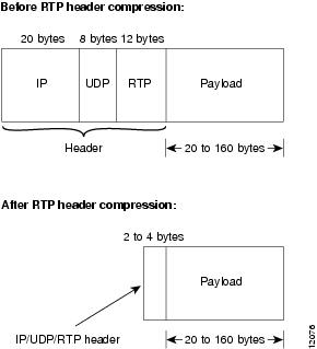
RTP is used for carrying packetized audio traffic over an IP network. RTP header compression compresses the IP/UDP/RTP header in an RTP data packet from 40 bytes to approximately 2 to 4 bytes (most of the time), as shown in Figure 4-1.
This compression feature is beneficial if you are running Voice over IP over slow links. Enabling compression on both ends of a low-bandwidth serial link can greatly reduce the network overhead if there is a lot of RTP traffic on that slow link.
Typically, an RTP packet has a payload of approximately 20 to 160 bytes for audio applications that use compressed payloads. RTP header compression is especially beneficial when the RTP payload size is small (for example, compressed audio payloads between 20 and 50 bytes).
Figure 4-1 RTP Header Compression
You should configure RTP header compression if the following conditions exist in your network:
•![]() Slow links
Slow links
•![]() Need to save bandwidth
Need to save bandwidth
Note ![]() Do not use RTP header compression on links greater than 2 Mbps.
Do not use RTP header compression on links greater than 2 Mbps.
Perform the following tasks to configure RTP header compression for Voice over IP. The first task is required; the second task is optional.
•![]() Enabling RTP Header Compression on a Serial Interface
Enabling RTP Header Compression on a Serial Interface
•![]() Changing the Number of Header Compression Connections
Changing the Number of Header Compression Connections
Enabling RTP Header Compression on a Serial Interface
To use RTP header compression, you need to enable compression on both ends of a serial connection. To enable RTP header compression, use the following command in interface configuration mode:
ip rtp header-compression [passive]
If you include the passive keyword, the software compresses outgoing RTP packets only if incoming RTP packets on the same interface are compressed. If you use the command without the passive keyword, the software compresses all RTP traffic.
Changing the Number of Header Compression Connections
By default, the software supports a total of 16 RTP header compression connections on an interface. To specify a different number of RTP header compression connections, use the following command in interface configuration mode:
ip rtp compression connections number
RTP Header Compression Configuration Example
The following example enables RTP header compression for a serial interface:
interface serial 0
ip rtp header-compression
encapsulation ppp
ip rtp compression-connections 25
Configuring Custom Queuing
Some QoS features, such as IP RTP reserve and custom queuing, are based on the transport protocol and the associated port number. Real-time voice traffic is carried on UDP ports ranging from 16384 to 16624. This number is derived from the following formula:
16384 = 4(number of voice ports in the Cisco 7200 VXR router)
Custom queuing and other methods for identifying high-priority streams should be configured for these port ranges.
Configuring Weighted Fair Queuing
Weighted fair queuing ensures that queues do not starve for bandwidth and that traffic gets predictable service. Low-volume traffic streams receive preferential service; high-volume traffic streams share the remaining capacity, obtaining equal or proportional bandwidth.
In general, weighted fair queuing is used in conjunction with Multilink PPP with interleaving and RSVP or IP precedence to ensure voice packet delivery. Use weighted fair queuing with Multilink PPP to define how data will be managed; use RSVP or IP precedence to give priority to voice packets.
Configuring Number Expansion
In most corporate environments, the telephone network is configured so that you can reach a destination by dialing only a portion (an extension number) of the full E.164 telephone number. Voice over IP can be configured to recognize extension numbers and expand them into their full E.164 dialed number by using two commands in tandem: destination-pattern and num-exp. Before you configure these two commands, it is helpful to map individual telephone extensions with their full E.164 dialed numbers. This can be done easily by creating a number expansion table.
Creating a Number Expansion Table
In the example in Figure 4-2, a small company wants to use Voice over IP to integrate its telephony network with its existing IP network. The destination pattern (or expanded telephone number) associated with Router A (located to the left of the IP cloud) is (408) 555-xxxx, where xxxx identifies the individual dial peers by extension. The destination pattern (or expanded telephone number) associated with Router B (located to the right of the IP cloud) is (729) 411-xxxx.
Figure 4-2 Sample Voice over IP Network
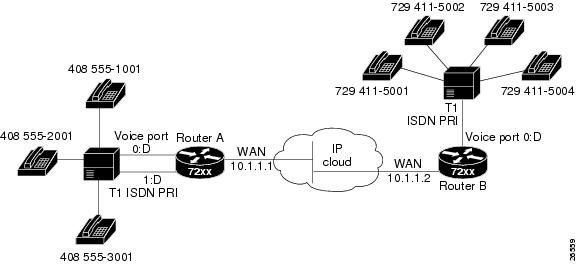
Table 4-6 shows the number expansion table for this scenario.
Note ![]() You can use the period symbol (.) to represent variables (such as extension numbers) in a telephone number.
You can use the period symbol (.) to represent variables (such as extension numbers) in a telephone number.
The information included in this example needs to be configured on both Router A and Router B.
Expanding a Number
To define how to expand an extension number into a particular destination pattern, use the following command in global configuration mode:
num-exp extension-number extension-string
You can verify the number expansion information by using the show num-exp command to verify that you have mapped the telephone numbers correctly.
After you have configured dial peers and assigned destination patterns to them, you can verify number expansion information by using the show dialplan number command to see how a telephone number maps to a dial peer.
Configuring Dial Peers
The key point to understanding how Voice over IP functions is to understand dial peers. Each dial peer defines the characteristics associated with a call leg, as shown in Figure 4-3 and Figure 4-4. A call leg is a discrete segment of a call connection that lies between two points in the connection. All of the call legs for a particular connection have the same connection ID.
There are two different kinds of dial peers:
•![]() POTS—Dial peer describing the characteristics of a traditional telephony network connection. POTS peers point to a particular voice port on a voice network device.
POTS—Dial peer describing the characteristics of a traditional telephony network connection. POTS peers point to a particular voice port on a voice network device.
•![]() VoIP—Dial peer describing the characteristics of a packet network connection; in the case of Voice over IP, this is an IP network. VoIP peers point to specific VoIP devices.
VoIP—Dial peer describing the characteristics of a packet network connection; in the case of Voice over IP, this is an IP network. VoIP peers point to specific VoIP devices.
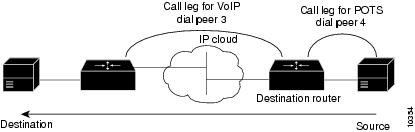
An end-to-end call comprises four call legs, two from the perspective of the source router as shown in Figure 4-3, and two from the perspective of the destination router as shown in Figure 4-4. A dial peer is associated with each one of these call legs. Dial peers are used to apply attributes to call legs and to identify call origin and destination. Attributes applied to a call leg include QoS, codec, VAD, and fax rate.
Figure 4-3 Dial Peer Call Legs from the Perspective of the Source Router
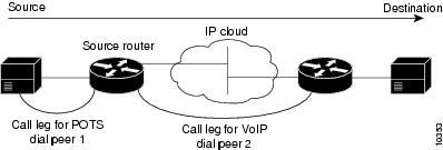
Figure 4-4 Dial Peer Call Legs from the Perspective of the Destination Router
Inbound Versus Outbound Dial Peers
Dial peers are used for both inbound and outbound call legs. It is important to remember that these terms are defined from the router's perspective. An inbound call leg originates outside the router. An outbound call leg originates from the router.
For inbound call legs, a dial peer might be associated with the calling number or the port designation. Outbound call legs always have a dial peer associated with them. The destination pattern is used to identify the outbound dial peer. The call is associated with the outbound dial peer at setup time.
POTS peers associate a telephone number with a particular voice port so that incoming calls for that telephone number can be received and outgoing calls can be placed. VoIP peers point to specific devices (by associating destination telephone numbers with a specific IP address) so that incoming calls can be received and outgoing calls can be placed. Both POTS and VoIP peers are needed to establish Voice over IP connections.
Establishing communication using Voice over IP is similar to configuring an IP static route; you are establishing a specific voice connection between two defined endpoints. As shown in Figure 4-5, for outgoing calls (from the perspective of the POTS dial peer 1), the POTS dial peer establishes the source (through the originating telephone number or voice port) of the call. The VoIP dial peer establishes the destination by associating the destination telephone number with a specific IP address.
Figure 4-5 Outgoing Calls from the Perspective of POTS Dial Peer 1
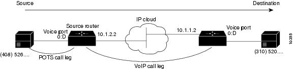
To configure call connectivity between the source and destination as illustrated in Figure 4-5, enter the following commands on router 10.1.2.2:
dial-peer voice 1 pots
destination-pattern 1408526....
port 1/0/0
dial-peer voice 2 voip
destination-pattern 1310520....
session target ipv4:10.1.1.2
In the previous configuration example, the last four digits in the VoIP dial peer's destination pattern were replaced with wildcards. This means that from router 10.1.2.2, calling any number string that begins with the digits "1310520" results in a connection to router 10.1.1.2. This implies that router 10.1.1.2 services all numbers beginning with those digits. From router 10.1.1.2, calling any number string that begins with the digits "1408526" will result in a connection to router 10.1.2.2. This implies that router 10.1.2.2 services all numbers beginning with those digits. For more information about stripping and adding digits, see the "Outbound Dialing on POTS Peers" section.
Figure 4-6 shows how to complete the end-to-end call between dial peer 1 and dial peer 4.
Figure 4-6 Outgoing Calls from the Perspective of POTS Dial Peer 2
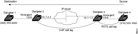
To complete the end-to-end call between dial peer 1 and dial peer 4 as illustrated in Figure 4-6, enter the following commands on router 10.1.1.2:
dial-peer voice 4 pots
destination-pattern 1310555....
port 1/0/0
dial-peer voice 3 voip
destination-pattern 1408555....
session target ipv4:10.1.2.2
Creating a Peer Configuration Table
There is specific data relative to each dial peer that needs to be identified before you can configure dial peers in Voice over IP. One way to do this is to create a peer configuration table.
Using the example in Figure 4-2, Router A, with an IP address of 10.1.1.1, connects a small sales branch office to the main office through Router B. There are three telephones in the sales branch office that need to be established as dial peers. Router B, with an IP address of 10.1.1.2, is the primary gateway to the main office; as such, it needs to be connected to the company's PBX. There are four devices that need to be established as dial peers in the main office, all of which are basic telephones connected to the PBX. Figure 4-2 shows a diagram of this small voice network.
Table 4-7 shows the peer configuration table for the example illustrated in Figure 4-2.
Configuring POTS Peers
POTS peers enable incoming calls to be received by a particular telephony device. To configure a POTS peer, you need to uniquely identify the peer (by assigning it a unique tag number), define its telephone numbers, and associate it with a voice port through which calls will be established. Under most circumstances, the default values for the remaining dial-peer configuration commands will be sufficient to establish connections.
To enter the dial-peer configuration mode (and select POTS as the method of voice-related encapsulation), use the following command in global configuration mode:
dial-peer voice number pots
The number value of the dial-peer voice pots command is a tag that uniquely identifies the dial peer. (This number has local significance only.)
To configure the identified POTS peer, use the following commands in dial-peer configuration mode:
Outbound Dialing on POTS Peers
When a router receives a voice call, it selects an outbound dial peer by comparing the called number (the full E.164 telephone number) in the call information with the number configured as the destination pattern for the POTS peer. The router then strips out the left-justified numbers corresponding to the destination pattern matching the called number. If you have configured a prefix, the prefix will be put in front of the remaining numbers, creating a dial string, which the router will then dial. If all numbers in the destination pattern are stripped out, the user receives (depending on the attached equipment) a dial tone.
For example, suppose there is a voice call whose E.164 called number is 1 (310) 767-2222. If you configure a destination pattern of "1310767" and a prefix of "9," the router strips out "1310767" from the E.164 telephone number, leaving the extension number of "2222." It then appends the prefix "9" to the front of the remaining numbers, so that the actual numbers dialed are "9, 2222." The comma in this example means that the router will pause for one second between dialing the "9" and the "2" to allow for a secondary dial tone.
Direct Inward Dial for POTS Peers
Direct inward dial (DID) is used to determine how the called number is treated for incoming POTS call legs. As shown in Figure 4-7, incoming means from the perspective of the router. In this case, it is the call leg coming into the router to be forwarded through to the appropriate destination pattern.
Figure 4-7 Incoming and Outgoing POTS Call Legs
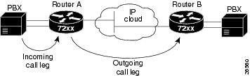
Unless otherwise configured, when a call arrives on the router, the router presents a dial tone to the caller and collects digits until it can identify the destination dial peer. After the dial peer has been identified, the call is forwarded through the next call leg to the destination.
There are cases when it might be necessary for the router to use the called number Dialed Number Identification Service (DNIS) to find a dial peer for the outgoing call leg—for example, if the switch connecting the call to the router has already collected the digits. DID enables the router to match the called number with a dial peer and then directly place the outbound call. With DID, the router does not present a dial tone to the caller and does not collect digits; it forwards the call directly to the configured destination.
To use DID and an incoming called number, a dial peer must be associated with the incoming call leg. It is helpful to understand the logic behind the algorithm used to associate the incoming call leg with the dial peer.
The algorithm used to associate incoming call legs with dial peers uses three inputs (which are derived from signaling and interface information associated with the call) and four defined dial peer elements. The three signaling inputs are:
•![]() Called number (DNIS)—Set of numbers representing the destination, which is derived from the ISDN setup message or CAS DNIS.
Called number (DNIS)—Set of numbers representing the destination, which is derived from the ISDN setup message or CAS DNIS.
•![]() Calling number (ANI)—Set of numbers representing the origin, which is derived from the ISDN setup message or CAS DNIS.
Calling number (ANI)—Set of numbers representing the origin, which is derived from the ISDN setup message or CAS DNIS.
•![]() Voice port—Voice port carrying the call.
Voice port—Voice port carrying the call.
The four defined dial peer elements are:
•![]() Destination pattern—Pattern representing the phone numbers to which the peer can connect.
Destination pattern—Pattern representing the phone numbers to which the peer can connect.
•![]() Answer address—Pattern representing the phone numbers from which the peer can connect.
Answer address—Pattern representing the phone numbers from which the peer can connect.
•![]() Incoming called number—Pattern representing the phone numbers that associate an incoming call leg to a peer based on the called number or DNIS.
Incoming called number—Pattern representing the phone numbers that associate an incoming call leg to a peer based on the called number or DNIS.
•![]() Port—Port through which calls to this peer are placed.
Port—Port through which calls to this peer are placed.
Using the elements, the algorithm is as follows:
For all peers where call type (VoIP versus POTS) matches dial peer type:
if the type is matched, associate the called number with the incoming called-number
else if the type is matched, associate calling-number with answer-address
else if the type is matched, associate calling-number with destination-pattern
else if the type is matched, associate voice port to port
This algorithm shows that if a value is not configured for answer address, the origin address is used because, in most cases, the origin address and answer address are the same.
To configure DID for a particular POTS dial peer, use the following commands, initially in global configuration mode:
|
|
|
|
|---|---|---|
Step 1 |
dial-peer voice number pots |
Enter the dial-peer configuration mode to configure a POTS peer. |
Step 2 |
direct-inward-dial |
Specify direct inward dial for this POTS peer. |
Note ![]() Direct inward dial is configured for the calling POTS dial peer.
Direct inward dial is configured for the calling POTS dial peer.
Configuring VoIP Peers
VoIP peers enable outgoing calls to be made from a particular telephony device. To configure a VoIP peer, you need to uniquely identify the peer (by assigning it a unique tag number) and define its destination telephone number and destination IP address. As with POTS peers, under most circumstances, the default values for the remaining dial-peer configuration commands are adequate to establish connections.
To enter the dial-peer configuration mode (and select VoIP as the method of voice-related encapsulation), use the following command in global configuration mode:
dial-peer voice number voip
The number value of the dial-peer voice voip command is a tag that uniquely identifies the dial peer.
To configure the identified VoIP peer, use the following commands in dial-peer configuration mode:
Verifing Configuration
You can check the validity of your dial-peer configuration by performing the following tasks:
•![]() If you have relatively few dial peers configured, you can use the show dial-peer voice command to verify that the data configured is correct. Use this command to display a specific dial peer or to display all configured dial peers.
If you have relatively few dial peers configured, you can use the show dial-peer voice command to verify that the data configured is correct. Use this command to display a specific dial peer or to display all configured dial peers.
•![]() Use the show dialplan number command to show the dial peer to which a particular number (destination pattern) resolves.
Use the show dialplan number command to show the dial peer to which a particular number (destination pattern) resolves.
Tips
If you are having trouble connecting a call and you suspect the problem is associated with dial-peer configuration, you can try to resolve the problem by performing the following tasks:
•![]() Ping the associated IP address to confirm connectivity.
Ping the associated IP address to confirm connectivity.
•![]() Use the show dial-peer voice command to verify that the operational status of the dial peer is up.
Use the show dial-peer voice command to verify that the operational status of the dial peer is up.
•![]() Use the show dialplan number command on the local and remote routers to verify that the data is configured correctly on both.
Use the show dialplan number command on the local and remote routers to verify that the data is configured correctly on both.
•![]() If you have configured number expansion, use the show num-exp command to check that the partial number on the local router maps to the correct full E.164 telephone number on the remote router.
If you have configured number expansion, use the show num-exp command to check that the partial number on the local router maps to the correct full E.164 telephone number on the remote router.
•![]() If you have configured a codec value, there can be a problem if both VoIP dial peers on either side of the connection have incompatible codec values. Make sure that both VoIP peers have been configured with the same codec value.
If you have configured a codec value, there can be a problem if both VoIP dial peers on either side of the connection have incompatible codec values. Make sure that both VoIP peers have been configured with the same codec value.
•![]() Use the debug vpm spi command to verify the output string that the router dials is correct.
Use the debug vpm spi command to verify the output string that the router dials is correct.
•![]() Use the debug cch323 rtp command to check RTP packet transport.
Use the debug cch323 rtp command to check RTP packet transport.
•![]() Use the debug cch323 h225 command to check the call setup.
Use the debug cch323 h225 command to check the call setup.
Configuring Voice Ports
Voice ports on Cisco 7200 series, Cisco 7200 VXR, and Cisco 7500 series routers support three basic voice signaling types:
•![]() FXO—Foreign Exchange Office interface. The FXO interface allows a connection to be directed to the PSTN's central office (or to a standard PBX interface, if the local telecommunications authority permits). This interface is of value for off-premises extension applications.
FXO—Foreign Exchange Office interface. The FXO interface allows a connection to be directed to the PSTN's central office (or to a standard PBX interface, if the local telecommunications authority permits). This interface is of value for off-premises extension applications.
•![]() FXS—The Foreign Exchange Station interface allows connection for basic telephone equipment, key sets, and PBXs, and supplies ring, voltage, and dial tone.
FXS—The Foreign Exchange Station interface allows connection for basic telephone equipment, key sets, and PBXs, and supplies ring, voltage, and dial tone.
•![]() E&M—The "Ear and Mouth" interface (or "RecEive and TransMit" interface) allows connection for PBX trunk lines (tie lines). It is a signaling technique for two-wire and four-wire telephone and trunk interfaces.
E&M—The "Ear and Mouth" interface (or "RecEive and TransMit" interface) allows connection for PBX trunk lines (tie lines). It is a signaling technique for two-wire and four-wire telephone and trunk interfaces.
In general, voice-port commands define the characteristics associated with a particular voice-port signaling type. Under most circumstances, the default voice-port command values are adequate to configure FXO and FXS ports to transport voice data over your existing IP network. Because of the inherent complexities involved with PBX networks, E&M ports might need specific voice-port values configured, depending on the specifications of the devices in your telephony network.
Configuring FXO or FXS Voice Ports
Under most circumstances, the default voice-port values are adequate for both FXO and FXS voice ports. If you need to change the default configuration for these voice ports, perform the following tasks. Items included in Step 1 and Step 2 are required; items included in Step 3 are optional.
Step 1 ![]() Identify the voice port and enter the voice-port configuration mode by using the voice-port command.
Identify the voice port and enter the voice-port configuration mode by using the voice-port command.
Step 2 ![]() Configure the following mandatory voice-port parameters by using the indicated commands:
Configure the following mandatory voice-port parameters by using the indicated commands:
•![]() Dial type (FXO only) using the dial-type command
Dial type (FXO only) using the dial-type command
•![]() Signal type using the signal command
Signal type using the signal command
•![]() Call progress tone using the cptone command
Call progress tone using the cptone command
•![]() Ring frequency (FXS only) using the ring frequency command
Ring frequency (FXS only) using the ring frequency command
•![]() Ring number (FXO only) using the ring number command
Ring number (FXO only) using the ring number command
Step 3 ![]() Configure one or more of the following optional voice-port parameters by using the indicated commands:
Configure one or more of the following optional voice-port parameters by using the indicated commands:
•![]() PLAR connection mode using the connection plar command
PLAR connection mode using the connection plar command
•![]() Music threshold using the music-threshold command
Music threshold using the music-threshold command
•![]() Description using the description command
Description using the description command
•![]() Comfort noise (if VAD is activated—VAD is a dial-peer command) using the comfort-noise command
Comfort noise (if VAD is activated—VAD is a dial-peer command) using the comfort-noise command
To configure FXO and FXS voice ports, use the following commands beginning in privileged EXEC mode:
Validation Tips
You can check the validity of your voice-port configuration by performing the following tasks:
•![]() Pick up the handset of an attached telephony device and check for a dial tone.
Pick up the handset of an attached telephony device and check for a dial tone.
•![]() If you have dial tone, check for dual tone multifrequency (DTMF) detection. If the dial tone stops when you dial a digit, then the voice port is most likely configured properly.
If you have dial tone, check for dual tone multifrequency (DTMF) detection. If the dial tone stops when you dial a digit, then the voice port is most likely configured properly.
•![]() Use the show voice-port command to verify that the data configured is correct.
Use the show voice-port command to verify that the data configured is correct.
Troubleshooting Tips
If you are having trouble connecting a call and you suspect the problem is associated with voice-port configuration, you can try to resolve the problem by performing the following tasks:
•![]() Ping the associated IP address to confirm connectivity.
Ping the associated IP address to confirm connectivity.
•![]() Use the show voice-port command to make sure that the port is enabled. If the port is offline, use the no shutdown command.
Use the show voice-port command to make sure that the port is enabled. If the port is offline, use the no shutdown command.
•![]() If you have configured E&M interfaces, make sure that the values pertaining to your specific PBX setup, such as timing or type, are correct.
If you have configured E&M interfaces, make sure that the values pertaining to your specific PBX setup, such as timing or type, are correct.
•![]() Check to see if the voice network module has been correctly installed. For more information, refer to the installation document Voice Network Module and Voice Interface Card Configuration Note that came with your voice network module.
Check to see if the voice network module has been correctly installed. For more information, refer to the installation document Voice Network Module and Voice Interface Card Configuration Note that came with your voice network module.
Fine-Tuning FXO and FXS Voice Ports
Depending on the specifics of your particular network, you might need to adjust voice parameters involving timing, input gain, and output attenuation for FXO or FXS voice ports. Collectively, these commands are referred to as voice-port tuning commands.
Note ![]() In most cases, the default values for voice-port tuning commands are sufficient.
In most cases, the default values for voice-port tuning commands are sufficient.
To configure voice-port tuning for FXO and FXS voice ports, perform the following steps:
Step 1 ![]() Identify the voice port and enter the voice-port configuration mode using the voice-port command.
Identify the voice port and enter the voice-port configuration mode using the voice-port command.
Step 2 ![]() For each of the following parameters, select the appropriate value using the commands indicated:
For each of the following parameters, select the appropriate value using the commands indicated:
•![]() Input gain using the input gain command
Input gain using the input gain command
•![]() Output attenuation using the output attenuation command
Output attenuation using the output attenuation command
•![]() Echo cancel coverage using the echo-cancel enable and echo-cancel coverage commands
Echo cancel coverage using the echo-cancel enable and echo-cancel coverage commands
•![]() Nonlinear processing using the non-linear command
Nonlinear processing using the non-linear command
•![]() Initial digit timeouts using the timeouts initial command
Initial digit timeouts using the timeouts initial command
•![]() Interdigit timeouts using the timeouts interdigits command
Interdigit timeouts using the timeouts interdigits command
•![]() Timing other than timeouts, using the timing digit, timing inter-digit, timing pulse-digit, and timing pulse-inter-digit commands
Timing other than timeouts, using the timing digit, timing inter-digit, timing pulse-digit, and timing pulse-inter-digit commands
To fine-tune FXO or FXS voice ports, use the following commands beginning in privileged EXEC mode:
:
Note ![]() After you change any voice-port command, it is a good idea to cycle the port by using the shutdown and no shutdown commands.
After you change any voice-port command, it is a good idea to cycle the port by using the shutdown and no shutdown commands.
Configuring E&M Voice Ports
Unlike FXO and FXS voice ports, the default E&M voice-port parameters most likely are not sufficient to enable voice data transmission over your IP network. E&M voice-port values must match those specified by the particular PBX device to which the voice port is connected.
To configure an E&M voice port, perform the following steps. Items included in Step 1 and Step 2 are required; items included in Step 3 are optional.
Step 1 ![]() Identify the voice port and enter the voice-port configuration mode using the voice-port command.
Identify the voice port and enter the voice-port configuration mode using the voice-port command.
Step 2 ![]() For each of the following required parameters, select the appropriate parameter value using the commands indicated:
For each of the following required parameters, select the appropriate parameter value using the commands indicated:
•![]() Dial type using the dial-type command
Dial type using the dial-type command
•![]() Signal type using the signal command
Signal type using the signal command
•![]() Call progress tone using the cptone command
Call progress tone using the cptone command
•![]() Operation using the operation command
Operation using the operation command
•![]() Type using the type command
Type using the type command
•![]() Impedance using the impedance command
Impedance using the impedance command
Step 3 ![]() Select one or more of the following optional parameters, using the indicated commands:
Select one or more of the following optional parameters, using the indicated commands:
•![]() Connection mode using the connection plar command
Connection mode using the connection plar command
•![]() Music threshold using the music-threshold command
Music threshold using the music-threshold command
•![]() Description using the description command
Description using the description command
•![]() Comfort tone (if VAD is activated) using the comfort-noise command
Comfort tone (if VAD is activated) using the comfort-noise command
To configure E&M voice ports, use the following commands beginning in privileged EXEC mode:
Validation Tips
You can check the validity of your voice-port configuration by performing the following tasks:
•![]() Pick up the handset of an attached telephony device and check for a dial tone.
Pick up the handset of an attached telephony device and check for a dial tone.
•![]() If you have a dial tone, check for DTMF detection. If the dial tone stops when you dial a digit, then the voice port is most likely configured properly.
If you have a dial tone, check for DTMF detection. If the dial tone stops when you dial a digit, then the voice port is most likely configured properly.
•![]() Use the show voice-port command to verify that the data configured is correct.
Use the show voice-port command to verify that the data configured is correct.
Troubleshooting Tips
If you are having trouble connecting a call and you suspect the problem is associated with voice-port configuration, you can try to resolve the problem by performing the following tasks:
•![]() Ping the associated IP address to confirm connectivity.
Ping the associated IP address to confirm connectivity.
•![]() Use the show voice-port command to make sure that the port is enabled. If the port is offline, use the no shutdown command.
Use the show voice-port command to make sure that the port is enabled. If the port is offline, use the no shutdown command.
•![]() If you have configured E&M interfaces, make sure that the values pertaining to your specific PBX setup, such as timing or type, are correct.
If you have configured E&M interfaces, make sure that the values pertaining to your specific PBX setup, such as timing or type, are correct.
•![]() Check to see if the voice network module has been correctly installed. For more information, refer to the installation document Voice Network Module and Voice Interface Card Configuration Note that came with your voice network module.
Check to see if the voice network module has been correctly installed. For more information, refer to the installation document Voice Network Module and Voice Interface Card Configuration Note that came with your voice network module.
Fine-Tuning E&M Voice Ports
Depending on the specifics of your particular network, you may need to adjust voice parameters involving timing, input gain, and output attenuation for E&M voice ports. Collectively, these commands are referred to as voice-port tuning commands.
Note ![]() In most cases, the default values for voice-port tuning commands are sufficient.
In most cases, the default values for voice-port tuning commands are sufficient.
To configure voice-port tuning for E&M voice ports, perform the following steps:
Step 1 ![]() Identify the voice port and enter the voice-port configuration mode by using the voice-port command.
Identify the voice port and enter the voice-port configuration mode by using the voice-port command.
Step 2 ![]() For each of the following parameters, select the appropriate value, using the commands indicated:
For each of the following parameters, select the appropriate value, using the commands indicated:
•![]() Input gain using the input gain command
Input gain using the input gain command
•![]() Output attenuation using the output attenuation command
Output attenuation using the output attenuation command
•![]() Echo cancel coverage using echo-cancel enable and echo-cancel coverage commands
Echo cancel coverage using echo-cancel enable and echo-cancel coverage commands
•![]() Nonlinear processing using the non-linear command
Nonlinear processing using the non-linear command
•![]() Initial digit timeouts using the timeouts initial command
Initial digit timeouts using the timeouts initial command
•![]() Interdigit timeouts using the timeouts interdigit command
Interdigit timeouts using the timeouts interdigit command
•![]() Timing other than timeouts using the timing clear-wait, timing delay-duration, timing delay-start, timing dial-pulse min-delay, timing digit, timing inter-digit, timing pulse, timing pulse-inter-digit, timing wink-duration, and timing wink-wait commands
Timing other than timeouts using the timing clear-wait, timing delay-duration, timing delay-start, timing dial-pulse min-delay, timing digit, timing inter-digit, timing pulse, timing pulse-inter-digit, timing wink-duration, and timing wink-wait commands
To fine-tune E&M voice ports, use the following commands beginning in privileged EXEC mode
:
Note ![]() After you change any voice-port command, it is a good idea to cycle the port by using the shutdown and no shutdown commands.
After you change any voice-port command, it is a good idea to cycle the port by using the shutdown and no shutdown commands.
Optimizing Dial Peer and Network Interface Configurations
Depending on how you have configured your network interfaces, you might need to configure additional VoIP dial-peer parameters. This section describes the following topics:
•![]() Configuring IP Precedence for Dial Peers
Configuring IP Precedence for Dial Peers
•![]() Configuring RSVP for Dial Peers
Configuring RSVP for Dial Peers
•![]() Configuring Codec and VAD for Dial Peers
Configuring Codec and VAD for Dial Peers
Configuring IP Precedence for Dial Peers
If you want to give real-time voice traffic a higher priority than other network traffic, you can weight the voice data traffic associated with a particular VoIP dial peer by using IP precedence. IP precedence scales better than RSVP but provides no admission control.
To give real-time voice traffic precedence over other IP network traffic, use the following commands, beginning in global configuration mode:
In IP precedence, the numbers 1 through 5 identify classes for IP flows; the numbers 6 through 7 are used for network and backbone routing and updates.
For example, to ensure that voice traffic associated with VoIP dial peer 103 is given a higher priority than other IP network traffic, enter the following:
dial-peer voice 103 voip
ip precedence 5
In this example, when an IP call leg is associated with VoIP dial peer 103, all packets transmitted to the IP network through this dial peer have their precedence bits set to 5. If the networks receiving these packets have been configured to recognize precedence bits, the packets are given priority over packets with a lower configured precedence value.
Configuring RSVP for Dial Peers
If you have configured your WAN or LAN interfaces for RSVP, you must configure the QoS for any associated VoIP peers. To configure quality of service for a selected VoIP peer, use the following commands, beginning in global configuration mode:
Note ![]() We suggest that you select controlled-load for the requested quality of service.
We suggest that you select controlled-load for the requested quality of service.
For example, to specify guaranteed delay QoS for VoIP dial peer 108, enter the following:
dial-peer voice 108 voip
destination-pattern +1408528
req-qos guaranteed-delay
session target ipv4:10.0.0.8
In this example, every time a connection is made through VoIP dial peer 108, an RSVP reservation request is made between the local router, all intermediate routers in the path, and the final destination router.
To generate an SNMP trap message if the reserved QoS is less than the configured value for a selected VoIP peer, use the following commands, beginning from the global configuration mode:
Note ![]() RSVP reservations are only one-way. If you configure RSVP, the VoIP dial peers on both ends of the connection must be configured for RSVP.
RSVP reservations are only one-way. If you configure RSVP, the VoIP dial peers on both ends of the connection must be configured for RSVP.
Configuring Codec and VAD for Dial Peers
Coder-decoder (codec) and voice activity detection (VAD) for a dial peer determine how much bandwidth the voice session uses. Codec typically is used to transform analog signals into a digital bit stream and digital signals back into analog signals—in this case, it specifies the voice coder rate of speech for a dial peer. VAD is used to disable the transmission of silence packets.
Configuring Codec for a VoIP Dial Peer
To specify a voice coder rate for a selected VoIP peer, use the following commands, initially beginning in global configuration mode:
The default for the codec command is g729r8; normally the default configuration for this command is the most desirable. If, however, you are operating on a high-bandwidth network and voice quality is of the highest importance, you should configure the codec command for g711alaw or ulaw. Using this value results in better voice quality, but it also requires higher bandwidth requirements for voice.
For example, to specify a codec rate of G.711a-law for VoIP dial peer 108, enter the following:
dial-peer voice 108 voip
destination-pattern +1408528
codec g711alaw
session target ipv4:10.0.0.8
Configuring VAD for a VoIP Dial Peer
To disable the transmission of silence packets for a selected VoIP peer, use the following commands, beginning in global configuration mode:
|
|
|
|
|---|---|---|
Step 1 |
dial-peer voice number voip |
Enter the dial-peer configuration mode to configure a VoIP peer. |
Step 2 |
vad |
Disable the transmission of silence packets (enabling VAD). |
The default for the vad command is enabled; normally the default configuration for this command is the most desirable. If you are operating on a high-bandwidth network and voice quality is of the highest importance, you should disable vad. Using this value will result in better voice quality, but it will also require higher bandwidth requirements for voice.
For example, to enable VAD for VoIP dial peer 108, enter the following:
dial-peer voice 108 voip
destination-pattern +1408528
vad
session target ipv4:10.0.0.8
Configuring Voice over Frame Relay
You need to take certain factors into consideration when configuring Voice over IP for it to run smoothly over Frame Relay. A public Frame Relay cloud provides no guarantees for QoS. For real-time traffic to be transmitted in a timely manner, the data rate must not exceed the committed information rate (CIR), or there is the possibility that packets will be dropped. In addition, Frame Relay traffic shaping and RSVP are mutually exclusive. This is particularly important to remember if multiple data-link connection identifiers (DLCIs) are carried on a single interface.
For Frame Relay links with slow output rates (less than or equal to 64 kbps), where data and voice are being transmitted over the same PVC, we recommend the following solutions:
•![]() Separate DLCIs for voice and data—By providing a separate subinterface for voice and data, you can use the appropriate QoS tool per line. For example, each DLCI would use 32 kbps of a 64 kbps line.
Separate DLCIs for voice and data—By providing a separate subinterface for voice and data, you can use the appropriate QoS tool per line. For example, each DLCI would use 32 kbps of a 64 kbps line.
–![]() Apply adaptive traffic shaping to both DLCIs.
Apply adaptive traffic shaping to both DLCIs.
–![]() Use RSVP or IP precedence to prioritize voice traffic.
Use RSVP or IP precedence to prioritize voice traffic.
–![]() Use compressed RTP to minimize voice packet size.
Use compressed RTP to minimize voice packet size.
–![]() Use weighted fair queuing to manage voice traffic.
Use weighted fair queuing to manage voice traffic.
•![]() Lower MTU size—Voice packets are generally small. By lowering the maximum transmission unit (MTU) size (for example, to 300 bytes), large data packets can be broken up into smaller data packets that can more easily be interwoven with voice packets.
Lower MTU size—Voice packets are generally small. By lowering the maximum transmission unit (MTU) size (for example, to 300 bytes), large data packets can be broken up into smaller data packets that can more easily be interwoven with voice packets.
Note ![]() Lowering the MTU size affects data throughput speed.
Lowering the MTU size affects data throughput speed.
•![]() CIR equal to line rate—Make sure that the data rate does not exceed the CIR. This is accomplished through generic traffic shaping.
CIR equal to line rate—Make sure that the data rate does not exceed the CIR. This is accomplished through generic traffic shaping.
–![]() Use RSVP or IP precedence to prioritize voice traffic.
Use RSVP or IP precedence to prioritize voice traffic.
–![]() Use compressed RTP to minimize voice packet header size.
Use compressed RTP to minimize voice packet header size.
•![]() Traffic shaping—Use adaptive traffic shaping to throttle back the output rate based on the backward explicit congestion notification (BECN). If the feedback from the switch is ignored, packets (both data and voice) might be discarded. Because the Frame Relay switch does not distinguish between voice and data packets, voice packets could be discarded, which would result in a deterioration of voice quality.
Traffic shaping—Use adaptive traffic shaping to throttle back the output rate based on the backward explicit congestion notification (BECN). If the feedback from the switch is ignored, packets (both data and voice) might be discarded. Because the Frame Relay switch does not distinguish between voice and data packets, voice packets could be discarded, which would result in a deterioration of voice quality.
–![]() Use RSVP, compressed RTP, reduced MTU size, and adaptive traffic shaping based on BECN to hold the data rate to the CIR.
Use RSVP, compressed RTP, reduced MTU size, and adaptive traffic shaping based on BECN to hold the data rate to the CIR.
–![]() Use generic traffic shaping to obtain a low interpacket wait time. For example, set Bc to 4000 to obtain an interpacket wait of 125 ms.
Use generic traffic shaping to obtain a low interpacket wait time. For example, set Bc to 4000 to obtain an interpacket wait of 125 ms.
Voice over Frame Relay Configuration Example
For Frame Relay, it is customary to configure a main interface and several subinterfaces, one subinterface per PVC. The following example configures a Frame Relay main interface and a subinterface so that voice and data traffic can be successfully transported:
interface serial 1/1
MTU 300
no ip address
encapsulation frame-relay
no ip route-cache
no ip mroute-cache
fair-queue 64 256 1000
frame-relay ip rtp header-compression
interface serial 1/1.1
MTU 300
ip address 10.0.0.5 255.0.0.0
ip rsvp bandwidth 48 48
no ip route-cache
no ip mroute-cache
bandwidth 64
traffic-shape rate 32000 4000 4000
frame-relay interface-dlci 16
frame-relay ip rtp header-compression
In this configuration example, the main interface has been configured as follows:
•![]() MTU size is 300 bytes.
MTU size is 300 bytes.
•![]() No IP address is associated with this serial interface. The IP address must be assigned for the subinterface.
No IP address is associated with this serial interface. The IP address must be assigned for the subinterface.
•![]() Encapsulation method is Frame Relay.
Encapsulation method is Frame Relay.
•![]() Fair queuing is enabled.
Fair queuing is enabled.
•![]() IP RTP header compression is enabled
IP RTP header compression is enabled
The subinterface has been configured as follows:
•![]() MTU size is inherited from the main interface.
MTU size is inherited from the main interface.
•![]() IP address for the subinterface is specified.
IP address for the subinterface is specified.
•![]() Bandwidth is set to 64 kbps.
Bandwidth is set to 64 kbps.
•![]() RSVP is enabled to use the default value, which is 75 percent of the configured bandwidth.
RSVP is enabled to use the default value, which is 75 percent of the configured bandwidth.
•![]() Generic traffic shaping is enabled with 32 kbps CIR where Bc = 4000 bits and Be = 4000 bits.
Generic traffic shaping is enabled with 32 kbps CIR where Bc = 4000 bits and Be = 4000 bits.
•![]() Frame Relay DLCI number is specified.
Frame Relay DLCI number is specified.
•![]() IP RTP header compression is enabled.
IP RTP header compression is enabled.
Note ![]() When traffic bursts over the CIR, output rate is held at the speed configured for the CIR (for example, traffic will not go beyond 32 kbps if the CIR is set to 32 kbps).
When traffic bursts over the CIR, output rate is held at the speed configured for the CIR (for example, traffic will not go beyond 32 kbps if the CIR is set to 32 kbps).
For more information about Frame Relay, refer to the Cisco IOS Release 12.0 Wide-Area Networking Configuration Guide.
Checking the Configuration
After configuring the new interface, use the show commands to display the status of the new interface or all interfaces, and use the ping command to check connectivity. This section includes the following subsections:
•![]() Using show Commands to Verify the New Interface Status
Using show Commands to Verify the New Interface Status
•![]() Using the ping Command to Verify Network Connectivity
Using the ping Command to Verify Network Connectivity
Using show Commands to Verify the New Interface Status
Table 4-8 demonstrates how you can use the show commands to verify that new interfaces are configured and operating correctly and that the PA-MCX appears in them correctly. Sample displays of the output of selected show commands appear in the sections that follow. For complete command descriptions and examples, refer to the publications listed in the "Related Documentation" section on page viii.
Troubleshooting Tips
If information about the PA-MCX port adapter is not indicated in show command output, it is probably because the card type has not been specified.
Because the PA-MCX port adapter can be configured for E1 or T1 connectivity, you must specify the card type as E1 or T1, as described in "Performing a Basic Configuration" section. There is no default card type. The port adapter is not functional until the card type is set.
Note ![]() The outputs that appear in this document may not match the output you receive when running these commands. The outputs in this document are examples only.
The outputs that appear in this document may not match the output you receive when running these commands. The outputs in this document are examples only.
If an interface is shut down and you configured it as up, or if the displays indicate that the hardware is not functioning properly, ensure that the interface is properly connected and terminated. If you still have problems bringing up the interface, contact a service representative for assistance. This section includes the following subsections:
•![]() Using the show version or show hardware Commands
Using the show version or show hardware Commands
•![]() Using the show interfaces Command
Using the show interfaces Command
Choose the subsection appropriate for your system. Proceed to the "Using the ping Command to Verify Network Connectivity" section when you have finished using the show commands.
Using the show version or show hardware Commands
Display the configuration of the system hardware, the number of each interface type installed, the Cisco IOS software version, the names and sources of configuration files, and the boot images, using the show version (or show hardware) command.
Note ![]() The outputs that appear in this document may not match the output you receive when running these commands. The outputs in this document are examples only.
The outputs that appear in this document may not match the output you receive when running these commands. The outputs in this document are examples only.
Following is an example of the show version command from a Cisco 7200 VXR router with the PA-MCX:
Router# show version
Cisco Internetwork Operating System Software
IOS (tm) 7200 Software (C7200-IS-M), Version 12.1(20000628:194205)]
Copyright (c) 1986-2000 by cisco Systems, Inc.
Compiled Fri 30-Jun-00 07:45 by nyv
Image text-base: 0x60008960, data-base: 0x612AE000
ROM: System Bootstrap, Version 12.0(19990210:195103) [12.0XE 104], DEVELOPMENT E
BOOTFLASH: 7200 Software (C7200-BOOT-M), Version 12.1(20000621:184]
Router uptime is 1 day, 2 hours, 22 minutes
System returned to ROM by reload
System image file is "tftp://172.168.0.0/c7200-is-mz.delt4"
cisco 7206VXR (NPE300) processor (revision B) with 57344K/40960K bytes of memor.
Processor board ID 11060156
R7000 CPU at 262Mhz, Implementation 39, Rev 1.0, 256KB L2, 2048KB L3 Cache
6 slot VXR midplane, Version 2.0
Last reset from power-on
Channelized E1, Version 1.0.
Bridging software.
X.25 software, Version 3.0.0.
Primary Rate ISDN software, Version 1.1.
4 Ethernet/IEEE 802.3 interface(s)
1 FastEthernet/IEEE 802.3 interface(s)
12 Serial network interface(s)
6 Channelized E1/PRI port(s)
12 Channelized T1/PRI port(s)
1 Voice resource(s)
125K bytes of non-volatile configuration memory.
20480K bytes of Flash PCMCIA card at slot 0 (Sector size 128K).
4096K bytes of Flash internal SIMM (Sector size 256K).
Configuration register is 0x0
Using the show diag Command
Display the types of port adapters installed in your system (and specific information about each) using the show diag slot command, where slot is the port adapter slot in a Cisco 7200 VXR router.
Note ![]() The outputs that appear in this document may not match the output you receive when running these commands. The outputs in this document are examples only.
The outputs that appear in this document may not match the output you receive when running these commands. The outputs in this document are examples only.
Following is an example of the show diag slot command that shows a PA-MCX in port adapter slot 5 of a Cisco 7200 VXR router:
Router# show diag 5
Slot 5:
PA-MCX-8TE1 Port adapter, 8 ports
Port adapter is analyzed
Port adapter insertion time 1d02h ago
EEPROM contents at hardware discovery:
Hardware Revision : 1.0
PCB Serial Number : 0001608`252
Part Number : 73-4118-01
Board Revision : 09
RMA Test History : 00
RMA Number : 0-0-0-0
RMA History : 00
Deviation Number : 0-0
Product Number : P@PA-MCX-8TE1
Top Assy. Part Number : 800-05358-01
EEPROM format version 4
EEPROM contents (hex):
0x00: 04 FF 40 01 7A 41 01 00 C1 8B 30 30 30 31 36 30
0x10: 38 60 32 35 32 82 49 10 16 01 42 30 39 03 00 81
0x20: 00 00 00 00 04 00 80 00 00 00 00 CB 94 50 40 50
0x30: 41 2D 4D 43 58 2D 38 54 45 31 20 20 20 20 20 20
0x40: 20 C0 46 03 20 00 14 EE 01 FF FF FF FF FF FF FF
0x50: FF FF FF FF FF FF FF FF FF FF FF FF FF FF FF FF
0x60: FF FF FF FF FF FF FF FF FF FF FF FF FF FF FF FF
0x70: FF FF FF FF FF FF FF FF FF FF FF FF FF FF FF FF
Using the show interfaces Command
The show interfaces command displays status information (including the physical slot and interface address) for the interfaces you specify. The example that follows specifies DSPfarm interfaces.
For complete descriptions of interface subcommands and the configuration options available for Cisco 7200 series interfaces, refer to the publications listed in the "Related Documentation" section on page viii.
Note ![]() The outputs that appear in this document may not match the output you receive when running these commands. The outputs in this document are examples only.
The outputs that appear in this document may not match the output you receive when running these commands. The outputs in this document are examples only.
Following is an example of the show interfaces serial command for Cisco 7200 VXR routers. In this example, the PA-MCX port adapter is located in port adapter slot 3.
Router# show interfaces serial 3/0
Serial3/0:0 is down, line protocol is down
Hardware is PA-MCX-2TE1
MTU 1500 bytes, BW 1984 Kbit, DLY 20000 usec,
reliability 255/255, txload 1/255, rxload 1/255
Encapsulation HDLC, crc 16, loopback not set
Keepalive set (10 sec)
Last input never, output never, output hang never
Last clearing of "show interface" counters never
Input queue: 0/75/0/0 (size/max/drops/flushes); Total output drops: 0
Queueing strategy: weighted fair
Output queue: 0/1000/64/0 (size/max total/threshold/drops)
Conversations 0/0/16 (active/max active/max total)
Reserved Conversations 0/0 (allocated/max allocated)
Available Bandwidth 1488 kilobits/sec
5 minute input rate 0 bits/sec, 0 packets/sec
5 minute output rate 0 bits/sec, 0 packets/sec
0 packets input, 0 bytes, 0 no buffer
Received 0 broadcasts, 0 runts, 0 giants, 0 throttles
0 input errors, 0 CRC, 0 frame, 0 overrun, 0 ignored, 0 abort
0 packets output, 0 bytes, 0 underruns
0 output errors, 0 collisions, 0 interface resets
0 output buffer failures, 0 output buffers swapped out
0 carrier transitions alarm present
Timeslot(s) Used:1-31, subrate: 64Kb/s, transmit delay is 0 flags
Serial3/1:0 is down, line protocol is down
Proceed to the next section, "Using the ping Command to Verify Network Connectivity," to check network connectivity of the PA-MCX and switch or router.
Using the ping Command to Verify Network Connectivity
Using the ping command, you can verify that an interface port is functioning properly. This section provides a brief description of this command. Refer to the publications listed in the "Related Documentation" section on page viii for detailed command descriptions and examples.
The ping command sends echo request packets out to a remote device at an IP address that you specify. After sending an echo request, the system waits a specified time for the remote device to reply. Each echo reply is displayed as an exclamation point (!) on the console terminal; each request that is not returned before the specified timeout is displayed as a period (.). A series of exclamation points (!!!!!) indicates a good connection; a series of periods (.....) or the messages [timed out] or [failed] indicate a bad connection.
Following is an example of a successful ping command to a remote server with the address 10.0.0.10:
Router# ping 10.0.0.10 <Return>
Type escape sequence to abort.
Sending 5, 100-byte ICMP Echoes to 10.0.0.10, timeout is 2 seconds:
!!!!!
Success rate is 100 percent (5/5), round-trip min/avg/max = 1/15/64 ms
Router#
If the connection fails, verify that you have the correct IP address for the destination and that the device is active (powered on), and repeat the ping command.
 Feedback