PA-4R-FDX Full-Duplex Token Ring Port Adapter Installation and Configuration
Available Languages
Table Of Contents
PA-4R-FDX Full-Duplex Token Ring Port Adapter Installation and Configuration
Port Adapter Installation Prerequisites
Software and Hardware Requirements
Checking Hardware and Software Compatibility
Verifying Full-Duplex Token Ring Port Adapter Capability in Your Router
Electrical Equipment Guidelines
Preventing Electrostatic Discharge Damage
Token Ring Connection Equipment
Token Ring Distance Limitations
Token Ring Speed Considerations
What Is the 4R-FDX Port Adapter?
Port Adapter Locations on the VIP2 and the Cisco 7200 Series Router
4R-FDX Port Adapter Receptacles, Cables, and Pinouts
4R-FDX Port Adapter Receptacle Pinout
VIP2 and the 4R-FDX Port Adapter
Installing or Replacing a Port Adapter on a VIP2
Attaching 4R-FDX Port Adapter Interface Cables
Determining Chassis Slot, Port Adapter, and Token Ring Interface Port Numbers
Configuring Full-Duplex Operation
Cisco 7200 Series and the 4R-FDX Port Adapter
Installing or Replacing a Port Adapter in Cisco 7200 Series Routers
Attaching 4R-FDX Port Adapter Interface Cables
Selecting Port Adapter Slot and Token Ring Interface Port Numbers
Configuring Full-Duplex Operation
Obtaining Technical Assistance
PA-4R-FDX Full-Duplex Token Ring Port Adapter Installation and Configuration
Product Number: PA-4R-FDX(=)
This configuration note describes how to install and configure the full-duplex Token Ring port adapter (PA-4R-FDX), which can be used in the following supported platforms:
•
Cisco 7200 series routers, which consists of the 2-slot Cisco 7202, 4-slot Cisco 7204, and the 6-slot Cisco 7206
•

Note
For Cisco 7200 series router users, use this configuration note in conjunction with the Cisco 72xx Installation and Configuration Guide that shipped with your Cisco 7200 series system.
Contents
This configuration note is organized into the following sections:
•
•
•
•
•
Port Adapter Installation Prerequisites
This section provides software requirements, a list of parts and tools you will need to perform the port adapter installation, and safety and ESD-prevention guidelines to help you avoid injury and damage to the equipment during installation. Also included is information on the systems in which port adapters can be installed and overview information on interface specifications.
The following sections discuss general information and information about port adapter installation requirements:
•
•
•
Software and Hardware Requirements
Following are specific hardware and software prerequisites to ensure proper operation of the 4R-FDX port adapter:
•
•
•
•
Note
In the Cisco 7000 series or Cisco 7500 series routers, the 4R port adapter requires the following VIP2 models:
•
•
•

Caution
Note
Checking Hardware and Software Compatibility
To check the minimum software requirements of Cisco IOS software with the hardware installed on your router, Cisco maintains the Software Advisor tool on Cisco.com. This tool does not verify whether modules within a system are compatible, but it does provide the minimum IOS requirements for individual hardware modules or components.
Note
To access Software Advisor, click Login at Cisco.com and go to Technical Support Help—Cisco TAC: Tool Index: Software Advisor. You can also access the tool by pointing your browser directly to http://www.cisco.com/cgi-bin/support/CompNav/Index.pl.
Choose a product family or enter a specific product number to search for the minimum supported software release needed for your hardware.
Verifying Full-Duplex Token Ring Port Adapter Capability in Your Router
The PA-4R-FDX port adapter supports full-duplex operation. (The PA-4R port adapter does not support full-duplex operation.) For a Token Ring interface to support full-duplex operation, it must be a PA-4R-FDX interface installed in a host router that is running the appropriate Cisco IOS software.
To determine if a Token Ring interface installed in your system supports full-duplex operation, use the show interfaces tokenring command. If the interface does not support full-duplex, the following message is displayed, and no changes are made to the interface:
%TokenRing5/0 interface does not support full-duplex.If you do not have the appropriate Cisco IOS software release and 4R-FDX port adapter installed in your system, you cannot configure full-duplex operation. For specific full-duplex configuration requirements, refer to the sections "Configuring Full-Duplex Operation," on page 24 (for operation with VIP2), and to "Configuring Full-Duplex Operation," on page 38 (for operation with Cisco 7200 series routers).
List of Parts and Tools
You need the following parts and tools to install a port adapter. If you need additional equipment, contact a service representative for ordering information.
•
–
–
•
•
•
Safety Guidelines
Following are safety guidelines that you should observe when working with any equipment that connects to electrical power or telephone wiring.
Safety Warnings
Electrical Equipment Guidelines
Follow these basic guidelines when working with any electrical equipment:
•
•
•
•
Telephone Wiring Guidelines
Use the following guidelines when working with any equipment that is connected to telephone wiring or to other network cabling:
•
•
•
•
Preventing Electrostatic Discharge Damage
Electrostatic discharge (ESD) damage, which can occur when electronic cards or components are improperly handled, results in complete or intermittent failures. Port adapters and processor modules comprise printed circuit boards that are fixed in metal carriers. Electromagnetic interference (EMI) shielding and connectors are integral components of the carrier. Although the metal carrier helps to protect the board from ESD, use a preventive antistatic strap during handling.
Following are guidelines for preventing ESD damage:
•
•
•
•
•
•
•
•
Caution
Token Ring Overview
The following sections describe Token Ring specifications, physical connections, connection equipment, and cables and connectors.
Token Ring Specifications
The term Token Ring refers to both IBM's Token Ring Network, which IBM developed in the 1970s, and to IEEE 802.5 networks. The IEEE 802.5 specification was modeled after, and still closely shadows, IBM's network. The two types are compatible, although the specifications differ slightly.
Token Ring and IEEE 802.5 are token passing networks, which move a small frame, called a token, around the network. Possession of the token grants the right to transmit; a station with information to transmit must wait until it detects a free token passing by.
The IBM Token Ring specifies a star topology, with all end stations connected through a device called a multistation access unit (MSAU) for half-duplex functionality or a Token Ring switch for full-duplex functionality. IEEE 802.5 does not specify any topology, although most implementations are based on a star configuration with end stations attached to a device called a media access unit (MAU) for half-duplex functionality or a Token Ring switch for full-duplex functionality. Also, IBM Token Ring specifies twisted-pair cabling, whereas IEEE 802.5 does not specify media type. Most Token Ring networks use shielded twisted-pair cabling; however, some networks that operate at 4 Mbps use unshielded twisted-pair cable. shows a comparison of the two types.
Figure 1 IBM Token Ring and IEEE 802.5 Comparison
All 4R-FDX port adapter interfaces support both 4- and 16-Mbps, half-duplex and full-duplex, operation and early token release. The default for all ports is for half-duplex 4-Mbps operation with early token release disabled. Both states are enabled with configuration commands in configuration mode.
To enable 16 Mbps, specify the slot/port address and use the configuration command ring-speed 16; to return to 4 Mbps operation, use the command ring-speed 4. To enable and disable early token release, specify the slot/port address and use the configuration command [no] early token release. To enable full-duplex operation, specify the slot/port address and use configuration command full-duplex. To return to half-duplex operation, use the no full-duplex or half-duplex command. For complete descriptions and examples of software commands, refer to the related software configuration documentation.
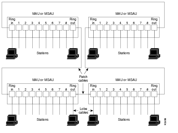
In the typical half-duplex Token Ring network, lobe cables connect each Token Ring station (4R-FDX port adapter interface) to the MSAU (or MAU), and patch cables connect adjacent MSAUs (or MAUs) to form one large ring. (See Figure 2.)
Figure 2 Half-Duplex Token Ring Network Physical Connections
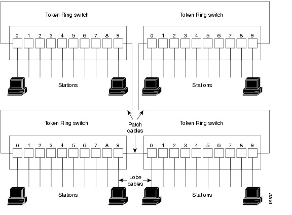
In the typical full-duplex Token Ring network, lobe cables connect each Token Ring station (4R-FDX port adapter interface) to the Token Ring switch, and patch cables connect adjacent Token Ring switches to form one large ring.Figure 3
Figure 3 Full-Duplex Token Ring Network Physical Connections
Token Ring Connection Equipment
You will need an 802.5 MAU, MSAU, or a Token Ring switch to provide the interface between the 4R-FDX port adapter Token Ring interfaces and the external ring, and a Token Ring lobe cable between each 4R-FDX port adapter interface and the MAU, MSAU, or the Token Ring switch. Lobe cables connect each Token Ring station (4R-FDX port adapter interface) to the MAU, MSAU, or Token Ring switch. Patch cables can connect adjacent MSAUs or Token Ring switches to form one large ring.
4R-FDX port adapter interfaces operate at either 4 or 16 Mbps. The default speed for all 4R-FDX port adapter interfaces is 4 Mbps, which you can change to 16 Mbps on any port by using the ring-speed n configuration command, where n is the speed (4 or 16) in Mbps. The speed of each Token Ring port must match the speed of the ring to which it is connected. Before you enable the Token Ring interfaces, ensure that each is set for the correct speed, or you risk bringing down the ring.
Caution
Token Ring Distance Limitations
The maximum transmission distance is not defined for IEEE 802.5 (Token Ring) networks. Shielded twisted-pair (STP) cabling is most commonly used for rates of 4 and 16 Mbps. Twisted-pair cabling is more susceptible to interference than other types of cabling; therefore, the network length and repeater spacing should be planned accordingly.
Token Ring Speed Considerations
Before you install the 4R-FDX port adapter, determine the ring speed (4 or 16 Mbps) of each ring to be connected to the server. There is no factory default for the interface speed; you must set the speed of each interface (within the setup command facility or with the ring-speed command) before you bring the interface up and insert it into the ring with the no shutdown command.
Caution
What Is the 4R-FDX Port Adapter?
The following sections provide additional information specific to the 4R-FDX port adapter.
•
•
The 4R-FDX port adapter (see ) provides up to four IBM Token Ring or IEEE 802.5 Token Ring interfaces. Each Token Ring interface can be set for 4 Mbps or 16 Mbps, half-duplex or full-duplex operation. All Token Ring ports run at wire speed.
Figure 4 4R-FDX Port Adapter, Faceplate View
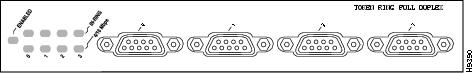
The 4R-FDX port adapter can be installed on the VIP2 in port adapter slot 0 and port adapter slot 1, or in the Cisco 7200 series routers in any of the chassis' port adapter slots: slot 1 and slot 2 of the Cisco 7202, slots 1 through 4 of the Cisco 7204,and slots 1 through 6 of the Cisco 7206.
Port Adapter Locations on the VIP2 and the Cisco 7200 Series Router
This section provides information about where you can install the 4R-FDX port adapter on the VIP2 and in the Cisco 7200 series routers.
Note
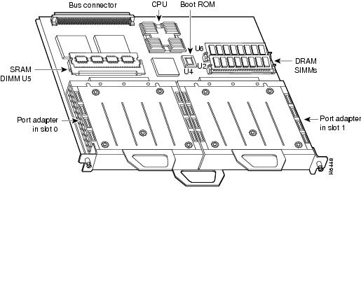
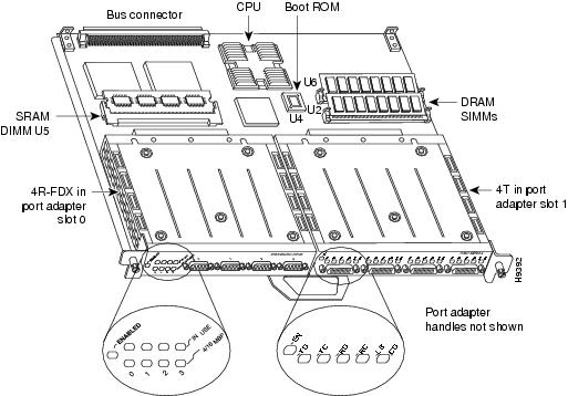
shows a VIP2-15 or VIP2-40 with two installed port adapters. With the VIP2 oriented as shown, the left port adapter is in port adapter slot 0, and the right port adapter is in port adapter slot 1.
Figure 5 Two Port Adapters on a VIP2-15 or VIP2-40 (Horizontal Orientation Shown)
Note
In the Cisco 7200 series routers, port adapter slots are numbered from the lower left to the upper right, beginning with port adapter slot 1 and continuing through port adapter slot 2 for the Cisco 7202, slot 4 for the Cisco 7204, and slot 6 for the Cisco 7206. Port adapter slot 0 is reserved for the optional Fast Ethernet port on the I/O controller.
Note
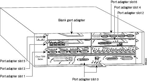
Figure 6Figure 6 shows a Cisco 7206 with installed port adapters and an I/O controller with a Fast Ethernet port. Not shown is the Cisco 7202, which has two port adapter slots, and the Cisco 7204, which has four port adapter slots. The 4R-FDX port adapter can be installed in any available port adapter slot in the Cisco 7200 series routers.
Figure 6 Port Adapters in the Cisco 7206
4R-FDX Port Adapter LEDs
The 4R-FDX port adapter has several LEDs that indicate status of the port adapter and its interfaces. The 4R-FDX port adapter's enabled LED (shown in ) goes on to indicate the following status of the 4R-FDX port adapter:
•
•
•
If any of these conditions is not met, or if the initialization fails for other reasons, the port adapter's enabled LED does not go on.
Figure 7 4R-FDX Port Adapter LEDs
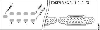
When a Token Ring interface is configured by using software commands, the In Ring and 4/16 Mbps LEDs (shown in ) indicate the following for each port:
•
•
4R-FDX Port Adapter Receptacles, Cables, and Pinouts
A network interface cable provides the connection between the 9-pin Token Ring receptacles on the 4R-FDX port adapter and a media access unit (MAU) or Token Ring switch. The 9-pin connector at the 4R-FDX port adapter end and the MAU or Token Ring switch connector at the network end are described in the section "Token Ring Connection Equipment" on page 9.
4R-FDX Port Adapter Cables
The Token Ring ports on the 4R-FDX port adapter are DB-9 (PC type) receptacles that require Type 1 or Type 3 lobe cables. Token Ring interface cables are not available from Cisco Systems, but are commercially available through outside cable vendors.
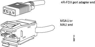
Type 1 lobe cables use shielded twisted-pair (STP) cable and terminate at the network end with a large MAU plug. (See Figure 8Figure 8.) The 4R-FDX port adapter end of the cable is a DB-9 plug.
Figure 8 Token Ring Type 1 Lobe Cable Connectors, DB-9 and MAU Types
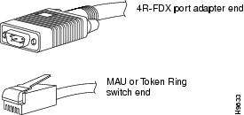
Type 3 lobe cables use either shielded or unshielded twisted-pair (UTP) cable and terminate at the network end with an RJ-11 plug. (See Figure 9.) The 4R-FDX port adapter end of the cable is a DB-9 plug.
Figure 9 Token Ring Type 3 Lobe Cable Connectors, DB-9 and RJ-11 Types
4R-FDX Port Adapter Receptacle Pinout
Table 1 lists the pinouts for the DB-9 receptacle used on the 4R-FDX port adapter.
Table 1 Token Ring Signals
VIP2 and the 4R-FDX Port Adapter
The following sections provide additional information specific to the 4R-FDX port adapter and its use on the VIP2 in Cisco 7000 series and Cisco 7500 series routers:
•
•
•
The 4R-FDX port adapter can be installed in port adapter slot 0 or port adapter slot 1 on the VIP2. Figure 10 shows a 4R-FDX port adapter installed on a VIP2 in port adapter slot 0.
Figure 10 VIP2 with a 4R-FDX Port Adapter in Port Adapter Slot 0
Note
Installing or Replacing a Port Adapter on a VIP2
Depending on the circumstances, you might need to install a new port adapter on a VIP2 motherboard or replace a failed port adapter in the field. In either case, you need a number 1 Phillips screwdriver, an antistatic mat onto which you can place the removed interface processor, and an antistatic container into which you can place a failed port adapter for shipment back to the factory.
Note
Caution
Note
While the VIP2 supports online insertion and removal, individual port adapters do not. To replace port adapters, you must first remove the VIP2 from the chassis, then install or replace port adapters as required. If a blank port adapter is installed on the VIP2 in which you want to install a new port adapter, you must first remove the VIP2 from the chassis, then remove the blank port adapter.
When only one port adapter is installed on a VIP2, a blank port adapter must fill the empty slot to allow the VIP2 and router chassis to conform to electromagnetic interference (EMI) emissions requirements, and to permit proper airflow through the chassis. If you plan to install a new port adapter, you must first remove the blank port adapter.
Following is the standard procedure for removing and replacing any type of port adapter on the VIP2:
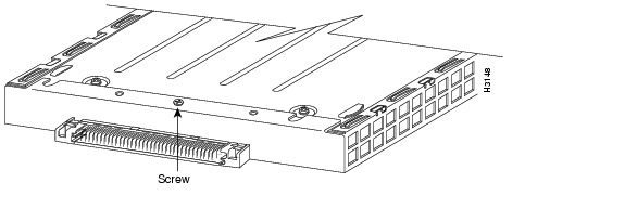
Step 1
Step 2
Step 3
Step 4
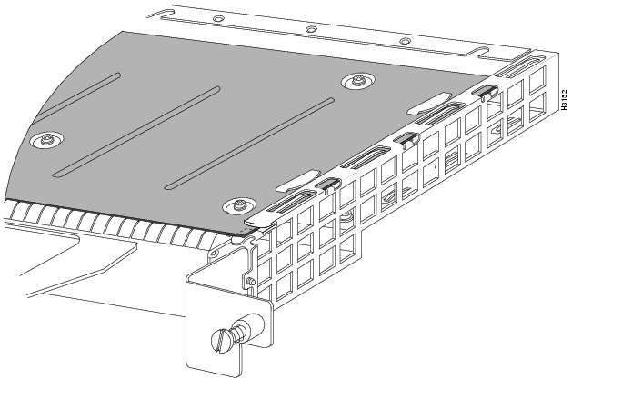
Figure 11 Location of Port Adapter Screw (Partial Port Adapter View)
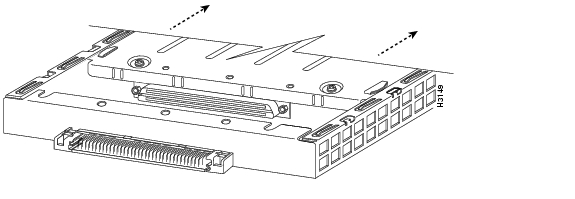
Step 5
Step 6
Figure 12 Pulling a Port Adapter Out of a Slot (Partial Port Adapter View)
Step 7
Step 8
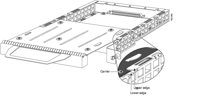
Step 9
Figure 13 Aligning a Port Adapter in a Port Adapter Slot
Caution
Caution
Step 10
Figure 14 Port Adapter Installed in a Port Adapter Slot (Partial Port Adapter View)
Step 11
Step 12
Step 13
This completes the procedure for installing a new port adapter or replacing a port adapter on a VIP2.
Attaching 4R-FDX Port Adapter Interface Cables
You need one Token Ring interface cable for each 4R-FDX port adapter interface you want to use. Token Ring interface cables are not available from Cisco Systems but are commercially available through outside cable vendors.
Use the following procedure to attach Token Ring cables to the 4R-FDX port adapter:
Step 1
Note
Step 2
Note
Figure 15 Token Ring Interface Cable Connections
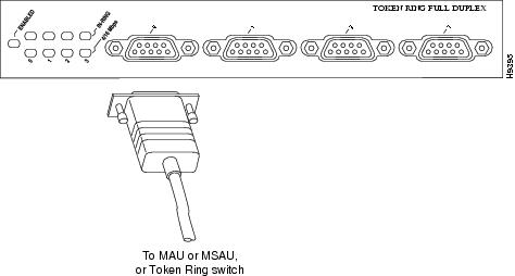
Caution
Step 3
This completes the procedure for attaching a 4R-FDX interface cable.
Configuring 4R-FDX Interfaces
If you installed a new 4R-FDX-equipped VIP2 or if you want to change the configuration of an existing interface, you must use the privileged-level configure command. If you replaced a 4R-FDX port adapter that was previously configured, the system will recognize the new 4R-FDX port adapter interfaces and bring each of them up in their existing configuration.
Note
After you verify that the new 4R-FDX port adapter is installed correctly (the enabled LED goes on), use the configure command to configure the new interfaces. Be prepared with the information you will need, such as the following:
•
•
•
Note
For complete descriptions of interface subcommands and the configuration options available for Cisco 7000 and Cisco 7500 series-related interfaces, refer to the publications listed in the section "Related Documentation" section.
Determining Chassis Slot, Port Adapter, and Token Ring Interface Port Numbers
This section describes how to identify chassis slot, port adapter, and Token Ring interface port numbers.
Note
In the router, physical port addresses specify the actual physical location of each interface port on the router interface processor end. (See Figure 16.) This address is composed of a three-part number in the format chassis slot number/port adapter number/interface port number:
•
•
•
Interface ports on the 4R-FDX port adapter maintain the same address regardless of whether other interface processors are installed or removed. However, when you move a VIP2 to a different slot, the first number in the address changes to reflect the new slot number.
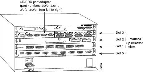
Figure 16 shows some of the port adapter slots and interface ports of a sample Cisco 7505 system. The first port adapter slot number is always 0. The second port adapter slot number is always 1. The individual interface port numbers always begin with 0. The number of additional ports depends on the number of ports on a port adapter.
For example, the addresses for the 4R-FDX interface ports on the first port adapter on a VIP2 (see Figure 16) are 3/0/0 through 3/0/3 (chassis slot 3, port adapter slot 0, and interface ports 0 through 3). If the 4R-FDX port adapter were installed in port adapter slot 1, the interface addresses would be 3/1/0 through 3/1/3.
Note
Figure 16 4R-FDX Token Ring Interface Port Number Example (Cisco 7505 Shown)
You can identify interface ports by physically checking the slot/port adapter/interface port location on the back of the router or by using software commands to display information about a specific interface or all interfaces in the router.
Shutting Down an Interface
Before you replace an interface cable, replace port adapters, or remove an interface that you will not replace, use the shutdown command to shut down (disable) the interfaces. Doing so prevents anomalies from occurring when you reinstall the new or reconfigured VIP2. You can shut down individual interfaces by specifying the chassis slot number, port adapter number, and interface port number. When you shut down an interface, it is designated administratively down in the show command displays.
Follow these steps to shut down an interface:
Step 1
Router> enableThe EXEC prompts you for a privileged level password:
Password:Step 2
For security purposes, the password is not displayed. (Also note that the password is case sensitive). When you enter the correct password, the system displays the privileged mode system prompt:
Router#Step 3
Router# configure terminalEnter configuration commands, one per line. End with CNTL/Z.Router(config)#Step 4
Router(config)# controller tokenring 3/1/0Step 5
Router(config-cont)# shutdownStep 6
Router# copy running-config startup-config[OK]Router#The system displays an OK message when the configuration has been stored.
Step 7
Router# show int tokenring 3/1/0TokenRing3/1/0 is down, line protocol is downHardware is cxBus Token Ring, address is 0000.0000.0000 (bia 0000.0000.0000)[display text omitted]Step 8
Router(config)# int tokenring 3/1/0Router(config-int)# no shutdownCtrl-ZRouter#Router# copy running-config startup-config[OK]Router# show int tokenring 3/1/0TokenRing3/1/0 is up, line protocol is upHardware is cxBus Token Ring, address is 0000.0000.0000 (bia 0000.0000.0000)[display text omitted]
For complete descriptions of software configuration commands, refer to the publications listed in the section "Related Documentation" section.
Configuring Interfaces
Following are instructions for a basic configuration using the configure command: enabling an interface setting interface ring speed, and specifying IP routing. You might also need to enter other configuration subcommands depending upon the requirements for your system configuration and the protocols you plan to route on the interface. For complete descriptions of configuration subcommands and the configuration options available, refer to the publications listed in the section "Related Documentation" section.
Press the Return key after each step unless otherwise noted. At any time you can exit the privileged level and return to the user level by entering disable at the prompt as follows:
Router# disableRouter>Following is an example of a basic configuration procedure:
Step 1
Router# conf t
Enter configuration commands, one per line. End with CNTL/Z. Router(config)#
Step 2
Router(config)# interface tokenring 3/0/0Step 3
Router(config-int)# ip address 1.1.1.10 255.255.255.0
Caution
Note
Step 4
Router(config-int)# no shutdownWhen you enable the interface by using the no shutdown command, the LED for 4 Mbps or 16 Mbps is turned on after about 5 seconds. The In Ring LED for that interface is turned on about 5 to 18 seconds later, when the port is initialized and connected to the ring.
Step 5
Router(config-int)# ring-speed 16Step 6
Step 7
Step 8
Step 9
Router# copy running-config startup-config[OK]Router#Step 10
Router# quit
You have completed configuring the Token Ring interfaces. To check the configuration, proceed to the following section "Checking the Configuration."
Note
Configuring Full-Duplex Operation
Full-duplex operation requires a 4R-FDX port adapter and a host router running a specific level of Cisco IOS software. (Refer to the section "Software and Hardware Requirements" section.)
Full-duplex operation is not the default configuration and must be turned on using the full-duplex command. To turn off full-duplex operation and reset the interface, use the no full-duplex or half-duplex command.
Following is an example of configuring a 4R-FDX interface for full-duplex operation using the full-duplex command:
Router# conf tEnter configuration commands, one per line. End with CNTL/Z.Router(config)# int tokenring 3/0/0Router(config-if)# full-duplexCtrl-zRouter#
Note
The output of the show interfaces tokenring slot/port-adapter/port command displays the state of the Token Ring port adapter interface and the state of full-duplex operation. Following is a partial sample output of this command from a 4R-FDX interface with full-duplex operation enabled:
Router# show int tokenring 3/0/0TokenRing3/0/0 is up, line protocol is upHardware is cxBus Token Ring, address is 0000.0000.0000 (bia 0000.0000.0000)Internet address is 14.0.0.2/8MTU 4464 bytes, BW 1600 Kbit, DLY 630 usec, rely 255/255, load 1/255Encapsulation SNAP, loopback not set, keepalive not setARP type: SNAP, ARP Timeout 04:00:00Ring speed: 16 Mbps, operating in full-duplex[display text omitted]
Note
Checking the Configuration
After configuring the new interface, use the show commands to display the status of the new interface or all interfaces, and the ping command to check connectivity.
Using show Commands to Verify the VIP2 Status
The following steps use show commands to verify that the new interfaces are configured and operating correctly.
Step 1
Step 2
Step 3
Step 4
Step 5
If the interface is down and you configured it as up, or if the displays indicate that the hardware is not functioning properly, ensure that the network interface is properly connected and terminated. If you still have problems bringing up the interface, contact a customer service representative for assistance.
To display information about a specific interface, use the show interfaces command with the interface type, chassis slot, port adapter, and interface port address in the format show interfaces [type slot/port adapter/port]. To display information about all interfaces installed in the system, use the show interfaces command without arguments.
The following example of the show interfaces tokenring [slot/port adapter/port] command shows information specific to the first 4R-FDX interface port (port 0) in chassis slot 3 and port adapter slot 0:
Router# sh int tokenring 3/0/0TokenRing3/0/0 is up, line protocol is upHardware is cxBus Token Ring, address is 0000.0000.0000 (bia 0000.0000.0000)Internet address is 14.0.0.2/8MTU 4464 bytes, BW 1600 Kbit, DLY 630 usec, rely 255/255, load 1/255Encapsulation SNAP, loopback not set, keepalive not setARP type: SNAP, ARP Timeout 04:00:00Ring speed: 16 Mbps, operating in full-duplex[display text omitted]The show version (or show hardware) command displays the configuration of the system hardware (the number of each interface processor type installed), the software version, the names and sources of configuration files, and the boot images. Following is an example of the show version command used with a Cisco 7500 series system:
Router# show versionCisco Internetwork Operating System SoftwareIOS (tm) GS Software (RSP-A), Version 11.1(8)CA [amcrae 125]Copyright (c) 1986-1996 by cisco Systems, Inc.Compiled Sat 10-Aug-96 17:56 by biffImage text-base: 0x600108A0, data-base: 0x60952000ROM: System Bootstrap, Version 5.3(16645) [szhang 571], INTERIM SOFTWAREROM: GS Software (RSP-BOOT-M), Version 11.1(8)CA, RELEASE SOFTWARE (fc1)Router uptime is 5 days, 4 minutesSystem restarted by reloadSystem image file is "rsp-jv-mz", booted via slot0cisco RSP2 (R4600) processor with 16384K bytes of memory.R4600 processor, Implementation 32, Revision 2.0Last reset from power-onG.703/E1 software, Version 1.0.Channelized E1, Version 1.0.SuperLAT software copyright 1990 by Meridian Technology Corp).Bridging software.X.25 software, Version 2.0, NET2, BFE and GOSIP compliant.TN3270 Emulation software (copyright 1994 by TGV Inc).Primary Rate ISDN software, Version 1.0.Chassis Interface.1 EIP controller (6 Ethernet).1 TRIP controller (4 Token Ring).2 MIP controllers (4 E1).1 VIP2 controller (2 E1)(4 Token Ring).6 Ethernet/IEEE 802.3 interfaces.8 Token Ring/IEEE 802.5 interfaces.3 Serial network interfaces.6 Channelized E1/PRI ports.125K bytes of non-volatile configuration memory.8192K bytes of Flash PCMCIA card at slot 0 (Sector size 128K).8192K bytes of Flash internal SIMM (Sector size 256K).No slave installed in slot 7.Configuration register is 0x0To determine which type of port adapter is installed on a VIP2 in your system, use the show diag slot command. Specific port adapter information is displayed, as shown in the following example of two 4R-FDX port adapters in chassis slot 3:
Router# show diag 3Slot 3:Physical slot 3, ~physical slot 0x7, logical slot 3, CBus 0Microcode Status 0x4Master Enable, LED, WCS LoadedBoard is analyzedPending I/O Status: NoneEEPROM format version 1VIP2 controller, HW rev 2.2, board revision UNKNOWNSerial number: 03341418 Part number: 73-1684-02Test history: 0x00 RMA number: 00-00-00Flags: cisco 7000 board; 7500 compatibleEEPROM contents (hex):0x20: 01 15 02 02 00 32 FC 6A 49 06 94 02 00 00 00 000x30: 07 2B 00 2A 1A 00 00 00 00 00 00 00 00 00 00 00Slot database information:Flags: 0x4 Insertion time: 0x3188 (01:20:53 ago)Controller Memory Size: 8 MBytesPA Bay 0 Information:Token Ring PA, 4 portsEEPROM format version 1HW rev 1.1, Board revision 0Serial number: 02827613 Part number: 73-1390-04PA Bay 1 Information:Token Ring PA, 4 portsEEPROM format version 1HW rev 1.1, Board revision 88Serial number: 02023786 Part number: 73-1390-04Using the ping and loopback Commands
The ping and loopback commands allow you to verify that an interface port is functioning properly and to check the path between a specific port and connected devices at various locations on the network, after the system has booted successfully and is operational. This section provides brief descriptions of these commands. Refer to the publications listed in the section "Related Documentation" section, for detailed command descriptions and examples.
The ping command sends echo request packets out to a remote device at an IP address that you specify. After sending an echo request, the command waits a specified time for the remote device to reply. Each echo reply is displayed as an exclamation point (!) on the console terminal; each request that is not returned before the specified timeout is displayed as a period (.). A series of exclamation points (!!!!!) indicates a good connection; a series of periods (.....) or the messages [timed out] or [failed] indicate that the connection failed.
Following is an example of a successful ping command to a remote server with the address 1.1.1.10:
Router# ping 1.1.1.10 <Return>Type escape sequence to abort.Sending 5, 100-byte ICMP Echoes to 1.1.1.10, timeout is 2 seconds:!!!!!Success rate is 100 percent (5/5), round-trip min/avg/max = 1/15/64 msRouter#If the connection fails, verify that you have the correct IP address for the destination and that the device is active (powered on), and repeat the ping command.
The loopback test allows you to detect and isolate equipment malfunctions by testing the connection between the 4R-FDX port adapter interface and a remote device such as a MAU, MSAU, or Token Ring switch. The loopback subcommand places an interface in loopback mode, which enables test packets that are generated from the ping command to loop through a remote device or interface cable. If the packets complete the loop, the connection is good. If not, you can isolate a fault to the remote device or interface cable in the path of the loopback test.
Note
When no interface cable is attached to a 4R-FDX port adapter interface, issuing the loopback controller command tests the path between the VIP2 and the interface port only (without leaving the VIP2 and port adapter).
For complete descriptions of interface subcommands and the configuration options available for Cisco 7000 and Cisco 7500 series-related interfaces, refer to the publications listed in the section "Related Documentation" section.
Cisco 7200 Series and the 4R-FDX Port Adapter
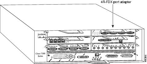
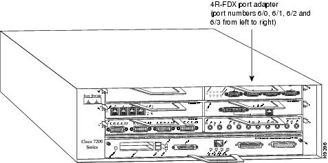
The 4R-FDX port adapter can be installed in any available port adapter slot in Cisco 7200 series routers (which consists of the 2-slot Cisco 7202, 4-slot Cisco 7204, and the 6-slot Cisco 7206). Figure 17 shows a 4R-FDX port adapter installed in port adapter slot 6 of a Cisco 7206.
Figure 17 Cisco 7206 with a 4R-FDX Port Adapter in Port Adapter Slot 6
The following sections include information specific to the 4R-FDX port adapter and its use in the Cisco 7200 series routers:
•
•
•
Installing or Replacing a Port Adapter in Cisco 7200 Series Routers
Depending on your circumstances, you might need to install a new port adapter in a Cisco 7200 series router or replace a failed port adapter in the field. In either case no tools are necessary; all port adapters available for the Cisco 7200 series connect directly to the router midplane and are locked into position by a port adapter lever. When removing and replacing a port adapter, you will need an antistatic mat onto which you can place a removed port adapter and an antistatic container into which you can place a failed port adapter for shipment back to the factory.
Note
When a port adapter slot is not in use, a blank port adapter must fill the empty slot to allow the router to conform to EMI emissions requirements and to allow proper air flow across the port adapters. If you plan to install a new port adapter in a slot that is not in use, you must first remove a blank port adapter.
Removing a Port Adapter
Following is the procedure for removing a port adapter from a Cisco 7200 series router:
Step 1
Step 2
Figure 18 Placing the Port Adapter Lever in the Unlocked Position (Cisco 7206 Shown)
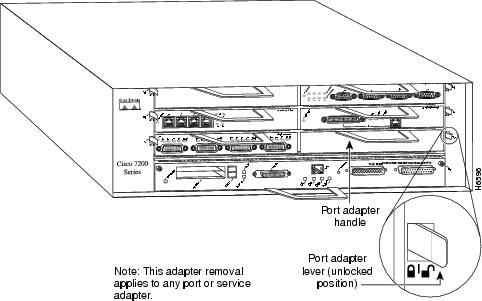
Step 3
Note
Step 4
Step 5
Caution
Figure 19 Handling a Port Adapter
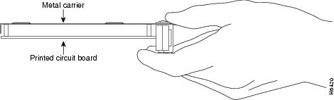
Step 6
This completes the procedure for removing a port adapter from a Cisco 7200 series router.
Replacing a Port Adapter
Following is the procedure for installing a new port adapter in a Cisco 7200 series router:
Step 1
Step 2
Step 3
Figure 20 Aligning the Port Adapter Metal Carrier Between the Slot Guides
(Cisco 7206 Shown)
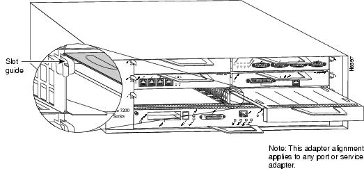
Step 4
Caution
Step 5
Step 6
Step 7
Note
Figure 21 Placing the Port Adapter Lever in the Locked Position (Cisco 7206 Shown)
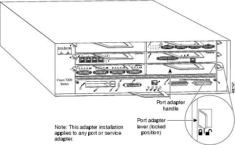
This completes the procedure for installing a new port adapter in a Cisco 7200 series router.
Attaching 4R-FDX Port Adapter Interface Cables
You need one Token Ring interface cable for each 4R-FDX port adapter interface you want to use. Token Ring interface cables are not available from Cisco Systems, but are commercially available through outside cable vendors.
Use the following procedure to attach Token Ring cables to the 4R-FDX port adapter:
Step 1
Note
Step 2
Note
Figure 22 Token Ring Interface Cable Connections
Caution
Step 3
This completes the procedure for attaching port adapter interface cables.
Configuring 4R-FDX Interfaces
If you installed a new 4R-FDX port adapter or if you want to change the configuration of an existing interface, you must use the privileged-level configure command. If you replaced a 4R-FDX port adapter that was previously configured, the system will recognize the new 4R-FDX port adapter interfaces and bring each of them up in their existing configuration.
Note
After you verify that the new 4R-FDX port adapter is installed correctly (the enabled LED goes on), use the configure command to configure the new interfaces. Be prepared with the information you will need, such as the following:
•
•
•
Note
For complete descriptions of interface subcommands and the configuration options available for Cisco 7200 series-related interfaces, refer to the publications listed in the section "Related Documentation" section.
Selecting Port Adapter Slot and Token Ring Interface Port Numbers
This section describes how to identify port adapter slot and Token Ring interface port numbers. In the router, physical port addresses specify the actual physical location of each interface port on the router. (See .) This address is composed of a two-part number in the format port adapter slot number/interface port number:
•
•
Interface ports on the 4R-FDX port adapter maintain the same address regardless of whether other port adapters are installed or removed. However, when you move a port adapter to a different slot, the first number in the address changes to reflect the new slot number.
In the Cisco 7200 series routers, port adapter slots are numbered from the lower left to the upper right, beginning with port adapter slot 1 and continuing through port adapter slot 2 for the Cisco 7202, slot 4 for the Cisco 7204, and slot 6 for the Cisco 7206. Port adapter slot 0 is reserved for the optional Fast Ethernet port on the I/O controller—if present. Figure 23 shows the port adapter slots and interface ports of a Cisco 7206.
Note
The individual interface port numbers always begin with 0. The number of additional ports depends on the number of ports on a port adapter. For example, the addresses of the interface ports on the 4R-FDX port adapter in slot 6 are 6/0 through 6/3 (chassis slot 6 and interface ports 0 through 3). If the 4R-FDX port adapter were installed in port adapter slot 4, the interface addresses would be 4/0 through 4/3.
Figure 23 4R-FDX Token Ring Interface Port Number Example
You can identify interface ports by physically checking the slot/interface port location on the back of the router or by using software commands to display information about a specific interface or all interfaces in the router.
Shutting Down an Interface
Before you replace an interface cable, replace port adapters, or remove an interface that you will not replace, use the shutdown command to shut down (disable) the interfaces. Doing so prevents anomalies from occurring when you reinstall the new or reconfigured port adapters. You can shut down individual interfaces by specifying the chassis slot number, port adapter number, and the interface port number. When you shut down an interface, it is designated administratively down in the show command displays.
Follow these steps to shut down an interface:
Step 1
Step 2
Router# configure terminalEnter configuration commands, one per line. End with CNTL/Z.Router(config)#Step 3
Router(config)# controller tokenring 3/0Step 4
Router(config-cont)# shutdownStep 5
Router# copy running-config startup-config[OK]Router#The system displays an OK message when the configuration has been stored.
Step 6
Router# show int tokenring 3/0TokenRing3/0 is down, line protocol is downHardware is IBM2692, address is 0000.0000.0000 (bia 0000.0000.0000)[display text omitted]Step 7
Router(config)# int tokenring 3/0Router(config-int)# no shutdownCtrl-ZRouter#Router# copy running-config startup-config[OK]Router# show int tokenring 3/0TokenRing3/0 is up, line protocol is upHardware is IBM2692, address is 0000.0000.0000 (bia 0000.0000.0000)[display text omitted]
For complete descriptions of software configuration commands, refer to the publications listed in the section "Related Documentation" section.
Configuring Interfaces
Following are instructions for a basic interface configuration using the configure command: enabling an interface, setting interface ring speed, and specifying IP routing. You might also need to enter other configuration subcommands depending upon the requirements for your system configuration. For complete descriptions of configuration subcommands and the configuration options available, refer to the publications listed in the section "Related Documentation" section.
Press the Return key after each step unless otherwise noted. At any time you can exit the privileged level and return to the user level by entering disable at the prompt as follows:
Router# disableRouter>Following is an example of a basic configuration procedure:
Step 1
Router# configure terminalEnter configuration commands, one per line. End with CNTL/Z.Step 2
Router(config)# interface tokenring 6/0Step 3
Router(config-int)# ip address 1.1.1.10 255.255.255.0
Caution
Note
Step 4
Router(config-int)# no shutdownWhen you enable the interface by using the no shutdown command, the LED for 4 Mbps or 16 Mbps is turned on after about 5 seconds. The In Ring LED for that interface is turned on about 5 to 18 seconds later, when the port is initialized and connected to the ring.
Step 5
Router(config-int)# ring-speed 16Step 6
Step 7
Step 8
Step 9
Router# copy running-config startup-config[OK]Router#
You have completed configuring the Token Ring interfaces. To check the configuration, proceed to the following section "Checking the Configuration" section.
Note
Configuring Full-Duplex Operation
Full-duplex operation requires a 4R-FDX port adapter and a host router running a specific level of Cisco IOS software. (Refer to the section "Software and Hardware Requirements" section.)
Full-duplex operation is not the default configuration and must be turned on using the full-duplex command. To turn off full-duplex operation and reset the interface, use the no full-duplex or half-duplex command.
Following is an example of configuring a 4R-FDX interface for full-duplex operation using the full-duplex command:
Router# conf tEnter configuration commands, one per line. End with CNTL/Z.Router(config)# int tokenring 6/0Router(config-if)# full-duplexCtrl-zRouter#
Note
The output of the show interfaces tokenring port adapter slot/interface port command displays the state of the Token Ring port adapter interface and the state of full-duplex operation. Following is a partial sample output of this command from a 4R-FDX interface with full-duplex operation enabled:
Router# show int tokenring 6/0TokenRing6/0 is up, line protocol is upHardware is IBM2692, address is 0000.0000.0000 (bia 0000.0000.0000)Internet address is 14.0.0.2/8MTU 4464 bytes, BW 1600 Kbit, DLY 630 usec, rely 255/255, load 1/255Encapsulation SNAP, loopback not set, keepalive not setARP type: SNAP, ARP Timeout 04:00:00Ring speed: 16 Mbps, operating in full-duplex[display text omitted]
Note
Checking the Configuration
After configuring the new interface, use the show commands to display the status of the new interface or all interfaces, and the ping command to check connectivity.
Using show Commands to Verify the Status of the New Interfaces
The following steps use show commands to verify that the new interfaces are configured and operating correctly.
Step 1
Step 2
Step 3
Step 4
Step 5
If the interface is down and you configured it as up, or if the displays indicate that the hardware is not functioning properly, ensure that the network interface is properly connected and terminated. If you still have problems bringing up the interface, contact a customer service representative for assistance.
To display information about a specific interface, use the show interfaces command with the interface type, port adapter slot, and interface port address in the format show interfaces [type port adapter slot/interface port]. To display information about all interfaces installed in the system, use the show interfaces command without arguments.
Following is an example of the show interfaces tokenring [port adapter slot/interface port] command shows information specific to the first 4R-FDX interface port (port 0) in port adapter slot 6:
Router# sh int tokenring 6/0TokenRing6/0 is up, line protocol is upHardware is IBM2692, address is 0000.0c0c.4444 (bia 0060.3e47.4360)Internet address is 14.0.0.2/8MTU 4464 bytes, BW 1600 Kbit, DLY 630 usec, rely 255/255, load 1/255Encapsulation SNAP, loopback not set, keepalive not setARP type: SNAP, ARP Timeout 04:00:00Ring speed: 16 Mbps, operating in full-duplex[display text omitted]The show version (or show hardware) command displays the configuration of the system hardware (the number of each interface type installed), the software version, the names and sources of configuration files, and the boot images. Following is an example of the show version command:
Router# show versionCisco Internetwork Operating System SoftwareIOS (tm) 7200 Software (C7200-J-M), Version 11.1(8)CA [rmontino 105]Copyright (c) 1986-1996 by cisco Systems, Inc.Compiled Sun 04-Aug-96 06:00 by rmontinoImage text-base: 0x600088A0, data-base: 0x605A4000ROM: System Bootstrap, Version 11.1(8)CA RELEASED SOFTWAREROM: 7200 Software (C7200-BOOT-M), RELEASED SOFTWARE 11.1(8)CA [gstovall 1]Router uptime is 4 hours, 22 minutesSystem restarted by reloadSystem image file is "c7200-j-mz", booted via slot0cisco 7206 (NPE150) processor with 12288K/4096K bytes of memory.R4700 processor, Implementation 33, Revision 1.0 (Level 2 Cache)Last reset from power-onBridging software.Channelized E1, Version 1.0.SuperLAT software copyright 1990 by Meridian Technology Corp.X.25 software, Version 2.0, NET2, BFE and GOSIP compliant.TN3270 Emulation software (copyright 1994 by TGV INC).Primary Rate ISDN software, Version 1.0.Chassis Interface.4 Ethernet/IEEE 802.3 interfaces.1 FastEthernet/IEEE 802.3 interface.4 Token Ring /IEEE802.5 interfaces.12 Serial network interfaces.2 Channelized E1/PRI ports.125K bytes of non-volatile configuration memory.1024K bytes of packet SRAM memory.20480K bytes of Flash PCMCIA card at slot 0 (Sector size 128K).8192K bytes of Flash internal SIMM (Sector size 256K).Configuration register is 0x2To determine which type of port adapter is installed in your Cisco 7200 series router, use the show diag slot command. Specific port adapter information is displayed, as shown in the following example of a 4R-FDX port adapter in port adapter slot 6:
Router# show diag 6Slot 6:Token-ring Full Duplex port adapter, 4 portsPort adapter is analyzedPort adapter insertion time 1d18h agoHardware revision 1.0 Board revision A0Serial number 2023868 Part number 73-1390-04Test history 0x0 RMA number 00-00-00EEPROM format version 1EEPROM contents (hex):0x20: 01 4A 01 01 00 1E E1 71 49 05 6E 04 00 00 00 000x30: 58 00 00 00 00 00 00 00 00 00 00 00 00 00 00 00For complete command descriptions and examples for the Cisco 7200 series routers, refer to the publications listed in the section "Related Documentation" section.
Using the ping and loopback Commands
The ping and loopback commands allow you to verify that an interface port is functioning properly and to check the path between a specific port and connected devices at various locations on the network, after the system has booted successfully and is operational. This section provides brief descriptions of these commands. Refer to the publications listed in the section "Related Documentation" section, for detailed command descriptions and examples.
The ping command sends echo request packets out to a remote device at an IP address that you specify. After sending an echo request, the command waits a specified time for the remote device to reply. Each echo reply is displayed as an exclamation point (!) on the console terminal; each request that is not returned before the specified timeout is displayed as a period (.). A series of exclamation points (!!!!!) indicates a good connection; a series of periods (.....) or the messages [timed out] or [failed] indicate that the connection failed.
Following is an example of a successful ping command to a remote server with the address 1.1.1.10:
Router# ping 1.1.1.10 <Return>Type escape sequence to abort.Sending 5, 100-byte ICMP Echoes to 1.1.1.10, timeout is 2 seconds:!!!!!Success rate is 100 percent (5/5), round-trip min/avg/max = 1/15/64 msRouter#If the connection fails, verify that you have the correct IP address for the destination and that the device is active (powered on), and repeat the ping command.
The loopback test allows you to detect and isolate equipment malfunctions by testing the connection between the 4R-FDX port adapter interface and a remote device such as a MAU, MSAU, or Token Ring switch. The loopback subcommand places an interface in loopback mode, which enables test packets that are generated from the ping command to loop through a remote device or interface cable. If the packets complete the loop, the connection is good. If not, you can isolate a fault to the remote device or interface cable in the path of the loopback test.
Note
When no interface cable is attached to a 4R-FDX port adapter interface, issuing the loopback controller command tests the path between the network processing engine and the interface port only (without leaving the network processing engine and port adapter).
For complete descriptions of interface subcommands and the configuration options available for Cisco 7200 series-related interfaces, refer to the publications listed in the section "Related Documentation" section.
Related Documentation
The documentation listed below is available online, on the Documentation CD-ROM, or as printed documents.
Your router, switch, or gateway and the Cisco IOS software running on it contain extensive features and functionality, which are documented in the following resources:
•
–
–
Note
•
For hardware installation and maintenance information, refer to the following publications:
–
–
•
–
–
–
–
•
For hardware installation and maintenance information, refer to the following publications:
–
–
•
–
–
–
–
•
–
–
Obtaining Documentation
These sections explain how to obtain documentation from Cisco Systems.
World Wide Web
You can access the most current Cisco documentation on the World Wide Web at this URL:
Translated documentation is available at this URL:
http://www.cisco.com/public/countries_languages.shtml
Documentation CD-ROM
Cisco documentation and additional literature are available in a Cisco Documentation CD-ROM package, which is shipped with your product. The Documentation CD-ROM is updated monthly and may be more current than printed documentation. The CD-ROM package is available as a single unit or through an annual subscription.
Ordering Documentation
You can order Cisco documentation in these ways:
•
http://www.cisco.com/cgi-bin/order/order_root.pl
•
http://www.cisco.com/go/subscription
•
Documentation Feedback
You can submit comments electronically on Cisco.com. In the Cisco Documentation home page, click the Fax or Email option in the "Leave Feedback" section at the bottom of the page.
You can e-mail your comments to bug-doc@cisco.com.
You can submit your comments by mail by using the response card behind the front cover of your document or by writing to the following address:
Cisco Systems
Attn: Document Resource Connection
170 West Tasman Drive
San Jose, CA 95134-9883We appreciate your comments.
Obtaining Technical Assistance
Cisco provides Cisco.com as a starting point for all technical assistance. Customers and partners can obtain online documentation, troubleshooting tips, and sample configurations from online tools by using the Cisco Technical Assistance Center (TAC) Web Site. Cisco.com registered users have complete access to the technical support resources on the Cisco TAC Web Site.
Cisco.com
Cisco.com is the foundation of a suite of interactive, networked services that provides immediate, open access to Cisco information, networking solutions, services, programs, and resources at any time, from anywhere in the world.
Cisco.com is a highly integrated Internet application and a powerful, easy-to-use tool that provides a broad range of features and services to help you with these tasks:
•
•
•
•
•
If you want to obtain customized information and service, you can self-register on Cisco.com. To access Cisco.com, go to this URL:
Technical Assistance Center
The Cisco Technical Assistance Center (TAC) is available to all customers who need technical assistance with a Cisco product, technology, or solution. Two levels of support are available: the Cisco TAC Web Site and the Cisco TAC Escalation Center.
Cisco TAC inquiries are categorized according to the urgency of the issue:
•
•
•
•
The Cisco TAC resource that you choose is based on the priority of the problem and the conditions of service contracts, when applicable.
Cisco TAC Web Site
You can use the Cisco TAC Web Site to resolve P3 and P4 issues yourself, saving both cost and time. The site provides around-the-clock access to online tools, knowledge bases, and software. To access the Cisco TAC Web Site, go to this URL:
All customers, partners, and resellers who have a valid Cisco service contract have complete access to the technical support resources on the Cisco TAC Web Site. The Cisco TAC Web Site requires a Cisco.com login ID and password. If you have a valid service contract but do not have a login ID or password, go to this URL to register:
http://www.cisco.com/register/
If you are a Cisco.com registered user, and you cannot resolve your technical issues by using the Cisco TAC Web Site, you can open a case online by using the TAC Case Open tool at this URL:
http://www.cisco.com/tac/caseopen
If you have Internet access, we recommend that you open P3 and P4 cases through the Cisco TAC Web Site.
Cisco TAC Escalation Center
The Cisco TAC Escalation Center addresses priority level 1 or priority level 2 issues. These classifications are assigned when severe network degradation significantly impacts business operations. When you contact the TAC Escalation Center with a P1 or P2 problem, a Cisco TAC engineer automatically opens a case.
To obtain a directory of toll-free Cisco TAC telephone numbers for your country, go to this URL:
http://www.cisco.com/warp/public/687/Directory/DirTAC.shtml
Before calling, please check with your network operations center to determine the level of Cisco support services to which your company is entitled: for example, SMARTnet, SMARTnet Onsite, or Network Supported Accounts (NSA). When you call the center, please have available your service agreement number and your product serial number.
This document is to be used in conjunction with the documents listed in the "Related Documentation <required for IOS - optional for other>" section.

Copyright © 1997-2002, Cisco Systems, Inc.
All rights reserved.

 Feedback
Contact Cisco
- Open a Support Case

- (Requires a Cisco Service Contract)