- Title and copyright: PA-8T-232 Synchronous Serial Port Adpater Installation and Configuration
- Preface: PA-8T-232 Synchronous Serial Port Adapter Installation and Configuration
- Overview: PA-8T-232 Synchronous Serial Port Adapter Installation and Configuration
- Preparing to Install the PA-8T-232 Synchronous Serial Port Adapter
- Removing and Installing the PA-8T-232 Synchronous Serial Port Adapter
- Attaching the PA-8T-232 Interface Cables
- Configuring the PA-8T-232 Synchronous Serial Port Adapter
- Port Adapter Overview
- Serial Interface Specifications
- LEDs
- Cables and Pinouts
- Port Adapter Slot Locations on the Supported Platforms
- Catalyst RSM/VIP2 Slot Numbering
- Catalyst 6000 Family FlexWAN Module Slot Numbering
- Cisco 7100 Series Routers Slot Numbering
- Cisco 7200 Series and Cisco uBR7200 Series Routers Slot Numbering
- Cisco 7301 Router Slot Numbering
- Cisco 7304 PCI Port Adapter Carrier Card Slot Numbering
- Cisco 7401ASR Router Slot Numbering
- VIP Slot Numbering
- Identifying Interface Addresses
- Catalyst RSM/VIP2 Interface Addresses
- Catalyst 6000 Family FlexWAN Module Interface Addresses
- Cisco 7100 Series Routers Interface Addresses
- Cisco 7200 Series and Cisco uBR7200 Series Routers Interface Addresses
- Cisco 7301 Router Interface Addresses
- Cisco 7304 PCI Port Adapter Carrier Card Interface Addresses
- Cisco 7401ASR Router Interface Addresses
- VIP Interface Addresses
Overview
This chapter describes the Cisco PA-8T-232 synchronous serial port adapter. This chapter contains the following sections:
•![]() Serial Interface Specifications
Serial Interface Specifications
•![]() LEDs
LEDs
•![]() Port Adapter Slot Locations on the Supported Platforms
Port Adapter Slot Locations on the Supported Platforms
•![]() Identifying Interface Addresses
Identifying Interface Addresses
Port Adapter Overview
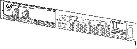
The PA-8T-232, shown in Figure 1-1, provides up to eight EIA/TIA-232 synchronous serial interfaces for Catalyst 5000 family switches (that use the Catalyst RSM/VIP2), Catalyst 6000 family switches (that use the Catalyst 6000 family FlexWAN module), Cisco 7000 series and Cisco 7500 series routers (that use the VIP), Cisco 7100 series routers, Cisco uBR7200 series routers, Cisco 7301 routers, Cisco 7304 routers (that use the Cisco 7304 PCI Port Adapter Carrier Card), and Cisco 7401ASR routers. The EIA/TIA-232 interfaces provide a direct connection between the high-speed bus in the router and external networks. Each EIA/TIA-232 interface provides full-duplex (FDX) operation at the rate of 64 kilobytes per second (kbps). The EIA/TIA-232 interface is most commonly used in the United States.
Figure 1-1 PA-8T-232—Faceplate View
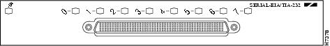
All eight interfaces connect to the external networks through a single port that has a 200-pin, D-shell receptacle. You must use an EIA/TIA-232 compact serial cable to connect interfaces to an external data service unit (DSU) or channel service unit (CSU). The compact serial cable attached to the single receptacle determines the mode (DCE or DTE) for all eight interfaces.

Note ![]() Although the Cisco 7304 PCI Port Adapter Carrier Card in the Cisco 7304 router, Catalyst RSM/VIP2, Catalyst 6000 family FlexWAN module, and VIP support online insertion and removal (OIR), individual port adapters do not. To replace port adapters, you must first remove the Cisco 7304 PCI Port Adapter Carrier Card in the Cisco 7304 router, the Catalyst RSM/VIP2, Catalyst 6000 family FlexWAN module, or VIP from the chassis and then replace port adapters as required.
Although the Cisco 7304 PCI Port Adapter Carrier Card in the Cisco 7304 router, Catalyst RSM/VIP2, Catalyst 6000 family FlexWAN module, and VIP support online insertion and removal (OIR), individual port adapters do not. To replace port adapters, you must first remove the Cisco 7304 PCI Port Adapter Carrier Card in the Cisco 7304 router, the Catalyst RSM/VIP2, Catalyst 6000 family FlexWAN module, or VIP from the chassis and then replace port adapters as required.
Cisco 7100 series, Cisco 7200 series, Cisco uBR7200 series routers, Cisco 7301 routers, and Cisco 7401ASR routers support online insertion and removal of all port adapter types.
The PA-8T-232 supports non return to zero (NRZ) and non return to zero inverted (NRZI) signaling, and both 16-bit and 32-bit cyclic redundancy checks (CRCs). The default configuration is for NRZ signaling and 16-bit CRC. You can change the default settings with software commands. (For more information, see the "Configuring the EIA/TIA-232 Interfaces" section.)
There is no default mode or clock rate set on serial ports, although an internal clock signal is present on all ports for DCE support. The internal clock also allows you to perform local loopback tests without having to terminate the port or connect a cable. To use the port as a DCE interface, you must set the clock rate and connect a DCE compact serial cable. To use the port as a DTE interface, you need only connect a DTE compact serial cable to the port. Because the serial adapter cables determine the mode and interface type, the PA-8T-232 interface becomes a DTE when you connect a DTE cable to it.
If you connect a DTE cable to a port with a clock rate set, the DTE ignores the clock rate and uses the external clock signal that is sent from the remote DCE. For a brief description of the clock rate command, see the "Configuring Timing (Clock) Signals" section. For complete command descriptions and instructions, refer to the publications listed in the "Related Documentation" section on page viii.
Serial Interface Specifications
Serial signals can travel a limited distance at any given bit rate; generally, the slower the bit rate, the greater the distance. All serial signals are subject to distance limits beyond which a signal degrades significantly or is completely lost. Table 1-1 lists recommended transmission speeds and distances for EIA/TIA-232 serial interfaces. The recommended maximum rate for EIA/TIA-232 is 64 kbps.
|
|
||
|---|---|---|
|
|
|
|
2400 |
200 |
60 |
4800 |
100 |
30 |
9600 |
50 |
15 |
19200 |
25 |
7.6 |
38400 |
12 |
3.7 |
56000 |
8.6 |
2.6 |
2048000 |
- |
- |
Note ![]() EIA/TIA-232 supports 64 kbps rates without any problems; however, we do not recommend you exceed the listed specifications for transmission speed versus distance. Do so at your own risk.
EIA/TIA-232 supports 64 kbps rates without any problems; however, we do not recommend you exceed the listed specifications for transmission speed versus distance. Do so at your own risk.
LEDs
The PA-8T-232 has one row of eight status LEDs (one for each port) and one enabled (EN) LED. (See Figure 1-2.) The green- and amber-colored LED for each port indicates port status.
Figure 1-2 LEDs on the PA-8T-232—Horizontal Orientation Shown
After system initialization, the enabled LED goes on to indicate that the port adapter is enabled for operation.
The following conditions must be met before the PA-8T-232 is enabled:
•![]() Port adapter is correctly connected to the backplane or midplane and receiving power.
Port adapter is correctly connected to the backplane or midplane and receiving power.
•![]() Valid system software image for the port adapter has been downloaded successfully.
Valid system software image for the port adapter has been downloaded successfully.
•![]() System recognizes the port adapter or PA-8T-232-equipped Catalyst RSM/VIP2, Catalyst 6000 family FlexWAN module, VIP, or Cisco 7304 PCI Port Adapter Carrier Card.
System recognizes the port adapter or PA-8T-232-equipped Catalyst RSM/VIP2, Catalyst 6000 family FlexWAN module, VIP, or Cisco 7304 PCI Port Adapter Carrier Card.
If any of the above conditions are not met, or if the initialization fails for other reasons, the enabled LED does not go on.
Table 1-2 lists port LED colors and indications.
Cables and Pinouts
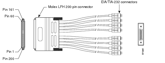
The compact serial cable for the PA-8T-232 is available in DTE or DCE mode with a 200-pin, D-shell plug at the router end and eight, 25-pin Winchester block-type receptacles or plugs at the network end. (See Figure 1-3.) The compact serial cable for the PA-8T-232 is 6 feet (1.8 meters) long.
Figure 1-3 EIA/TIA-232 Compact Serial Cable
Note ![]() The EIA/TIA-232 compact serial cable attached to the single PA-8T-232 port determines the mode (DTE or DCE) of the eight EIA/TIA-232 interfaces.
The EIA/TIA-232 compact serial cable attached to the single PA-8T-232 port determines the mode (DTE or DCE) of the eight EIA/TIA-232 interfaces.
Following are the product numbers, according to mode, for the EIA/TIA-232 compact serial cable:
•![]() DTE mode with a 25-pin Winchester-type EIA/TIA-232 plug (CAB-OCT-232-MT[=])
DTE mode with a 25-pin Winchester-type EIA/TIA-232 plug (CAB-OCT-232-MT[=])
•![]() DCE mode with a 25-pin Winchester-type EIA/TIA-232 receptacle (CAB-OCT-232-FC[=])
DCE mode with a 25-pin Winchester-type EIA/TIA-232 receptacle (CAB-OCT-232-FC[=])
Note ![]() Do not use the Cisco Systems-provided EIA/TIA-232 adapter cable CAB-OCT-232-MT= to connect a PA-8T-232 interface that is configured for DTE mode directly to an NEC - NEXTSTAR 1E model C4969 MD/SAC unit interface that is configured for DCE mode. Doing so prevents transmit and receive data signals from being properly exchanged between the two interfaces.
Do not use the Cisco Systems-provided EIA/TIA-232 adapter cable CAB-OCT-232-MT= to connect a PA-8T-232 interface that is configured for DTE mode directly to an NEC - NEXTSTAR 1E model C4969 MD/SAC unit interface that is configured for DCE mode. Doing so prevents transmit and receive data signals from being properly exchanged between the two interfaces.
Instead, you must connect an additional, intermediate adapter cable—with standard EIA/TIA-232 DB-25 connectors at both ends—from the network end of CAB-OCT-232-MT= to the standard EIA/TIA-232 DB-25 connector (the DCE interface) on the NEC - NEXTSTAR 1E model C4969 MD/SAC unit. Cisco Systems does not provide this additional cable; however, its signals and pin assignments are listed in Table 1-5.
Note ![]() You can use the Cisco Systems-provided EIA/TIA-232 adapter cable CAB-OCT-232-FC= to connect a PA-8T-232 interface that is configured for DCE mode directly to an NEC - NEXTSTAR 1E model C4969 MD/SAC unit interface that is configured for DTE mode.
You can use the Cisco Systems-provided EIA/TIA-232 adapter cable CAB-OCT-232-FC= to connect a PA-8T-232 interface that is configured for DCE mode directly to an NEC - NEXTSTAR 1E model C4969 MD/SAC unit interface that is configured for DTE mode.
Because the PA-8T-232 uses a special, high-density port that requires a special compact serial interface cable, we recommend that you obtain the cables from the factory.
Figure 1-4 shows the connectors at the network end of the EIA/TIA-232 compact serial cable.
Figure 1-4 EIA/TIA-232 Compact Serial Cable Connectors
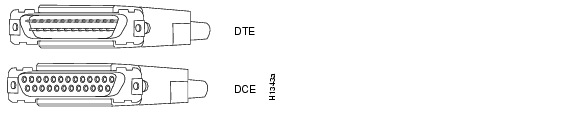
Table 1-3 lists connector pinouts for the EIA/TIA-232 DTE compact serial cable (CAB-OCT-232-MT[=]), and Table 1-4 lists connector pinouts for the EIA/TIA-232 DCE compact serial cable (CAB-OCT-232-FC[=]).
Port Adapter Slot Locations on the Supported Platforms
This section discusses port adapter slot locations on the supported platforms. The illustrations that follow summarize slot locations on each platform:
•![]() Catalyst RSM/VIP2 Slot Numbering
Catalyst RSM/VIP2 Slot Numbering
•![]() Catalyst 6000 Family FlexWAN Module Slot Numbering
Catalyst 6000 Family FlexWAN Module Slot Numbering
•![]() Cisco 7100 Series Routers Slot Numbering
Cisco 7100 Series Routers Slot Numbering
•![]() Cisco 7200 Series and Cisco uBR7200 Series Routers Slot Numbering
Cisco 7200 Series and Cisco uBR7200 Series Routers Slot Numbering
•![]() Cisco 7301 Router Slot Numbering
Cisco 7301 Router Slot Numbering
•![]() Cisco 7304 PCI Port Adapter Carrier Card Slot Numbering
Cisco 7304 PCI Port Adapter Carrier Card Slot Numbering
•![]() Cisco 7401ASR Router Slot Numbering
Cisco 7401ASR Router Slot Numbering
Catalyst RSM/VIP2 Slot Numbering
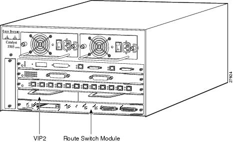
The Catalyst RSM/VIP2 can be installed in any slot except the top slots, which contain the supervisor engines. The Catalyst RSM/VIP2 in a Catalyst 5000 family switch does not use interface processor slot numbering; therefore, slots are not numbered in Figure 1-5. The PA-8T-232 can be installed into either port adapter slot 0 or slot 1 on a Catalyst RSM/VIP2. Figure 1-5 shows a Catalyst RSM/VIP2 with two port adapters installed.
Note ![]() The Catalyst 5500 switch has 13 slots. Slot 1 is reserved for the supervisor engine. If a redundant supervisor engine is used, it would go in slot 2; otherwise, slot 2 can be used for other modules. Slot 13 is a dedicated slot, reserved for the ATM Switch Processor (ASP) module. Refer to the Catalyst 5000 Series Route Switch Module Installation and Configuration Note for any additional slot restrictions for the Catalyst RSM/VIP2.
The Catalyst 5500 switch has 13 slots. Slot 1 is reserved for the supervisor engine. If a redundant supervisor engine is used, it would go in slot 2; otherwise, slot 2 can be used for other modules. Slot 13 is a dedicated slot, reserved for the ATM Switch Processor (ASP) module. Refer to the Catalyst 5000 Series Route Switch Module Installation and Configuration Note for any additional slot restrictions for the Catalyst RSM/VIP2.
Figure 1-5 Catalyst 5000 Family Switch with Port Adapters Installed on Catalyst RSM/VIP2
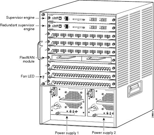
Catalyst 6000 Family FlexWAN Module Slot Numbering
The Catalyst 6000 family FlexWAN module can be installed in any slot except slot 1, which is reserved for the supervisor engine. The PA-8T-232 can be installed into either port adapter bay 0 or bay 1 on a FlexWAN module. Figure 1-6 shows a FlexWAN module with two blank port adapters installed.
Note ![]() Slot 1 is reserved for the supervisor engine. If a redundant supervisor engine is used, it would go in slot 2; otherwise, slot 2 can be used for other modules.
Slot 1 is reserved for the supervisor engine. If a redundant supervisor engine is used, it would go in slot 2; otherwise, slot 2 can be used for other modules.
Figure 1-6 Catalyst 6000 Family Switch with Blank Port Adapters Installed on FlexWAN Module
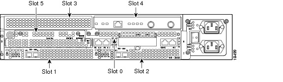
Cisco 7100 Series Routers Slot Numbering
The PA-8T-232 can be installed in port adapter slot 3 in Cisco 7120 series routers, and in port adapter slot 4 in Cisco 7140 series routers. Figure 1-7 shows a Cisco 7120 with a port adapter installed in slot 3. Figure 1-8 shows a Cisco 7140 with a port adapter installed in slot 4.
Figure 1-7 Port Adapter Slots in the Cisco 7100 Series Router—Cisco 7120 Series
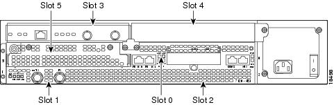
Figure 1-8 Port Adapter Slots in the Cisco 7100 Series Router—Cisco 7140 Series
Cisco 7200 Series and Cisco uBR7200 Series Routers Slot Numbering
Figure 1-9 shows a Cisco 7206 with port adapters installed. In the Cisco 7206, port adapter slot 1 is in the lower left position, and port adapter slot 6 is in the upper right position. (The Cisco 7202 and Cisco 7204 are not shown; however, the PA-8T-232 can be installed in any available port adapter slot.)
Figure 1-9 Port Adapter Slots in the Cisco 7206
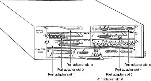
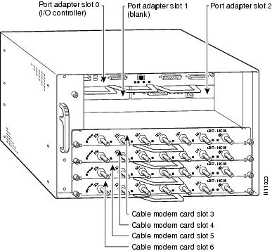
Figure 1-10 shows the slot numbering of port adapters in a Cisco uBR7246 and Cisco uBR7246VXR router. The port adapter slots are numbered slot 1 and slot 2 for the Cisco uBR7246 and Cisco uBR7246VXR router and slot 1 for the Cisco uBR7223. (Slot 0 is always reserved for the Fast Ethernet port on the I/O controller—if present.)
Figure 1-10 Port Adapter Slots in the Cisco uBR7246 and Cisco uBR7246VXR
Cisco 7301 Router Slot Numbering
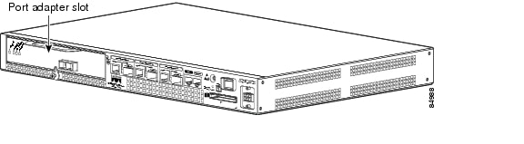
The Cisco 7301 router has one standard port adapter slot. See Figure 1-11.
Figure 1-11 Port Adapter Slot in the Cisco 7301 Router
Cisco 7304 PCI Port Adapter Carrier Card Slot Numbering
The Cisco 7304 PCI Port Adapter Carrier Card accepts one single-width port adapter. Figure 1-12 shows a Cisco 7304 PCI Port Adapter Carrier Card with a port adapter installed.
Figure 1-12 Cisco 7304 PCI Port Adapter Carrier Card—Port Adapter Installed
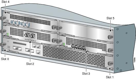
The Cisco 7304 PCI Port Adapter Carrier Card installs in Cisco 7304 router module slots 2 through 5. See Figure 1-13 for module slot numbering on a Cisco 7304 router.
Figure 1-13 Module Slots on the Cisco 7304 Router
Cisco 7401ASR Router Slot Numbering
Figure 1-14 shows the front view of a Cisco 7401ASR router with a port adapter installed. There is only one port adapter slot in a Cisco 7401ASR router.
Figure 1-14 Cisco 7401ASR Router with a Port Adapter Installed
VIP Slot Numbering
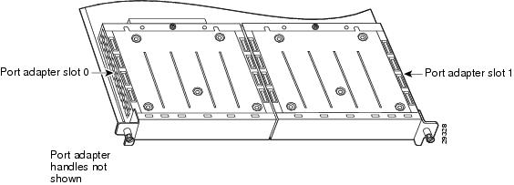
Figure 1-15 shows a partial view of a VIP motherboard with installed port adapters. With the motherboard oriented as shown in Figure 1-15, the left port adapter is in port adapter slot 0, and the right port adapter is in port adapter slot 1. The slot numbering is the same for the Catalyst RSM/VIP2. The slots are always numbered 0 and 1.
Figure 1-15 VIP Motherboard with Two Port Adapters Installed—Horizontal Orientation
Note ![]() In the Cisco 7000, Cisco 7507, and Cisco 7513 chassis, the VIP motherboard is installed vertically. In the Cisco 7010 and Cisco 7505 chassis, the VIP motherboard is installed horizontally.
In the Cisco 7000, Cisco 7507, and Cisco 7513 chassis, the VIP motherboard is installed vertically. In the Cisco 7010 and Cisco 7505 chassis, the VIP motherboard is installed horizontally.
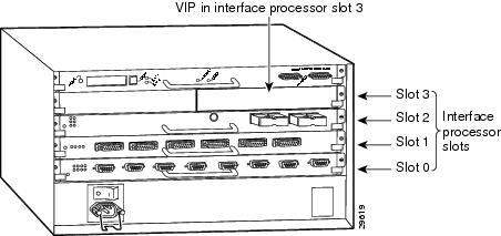
Interface processor slots are numbered as shown in Figure 1-16.
Figure 1-16 Interface Slot Numbers—Cisco 7505 shown
Identifying Interface Addresses
This section describes how to identify interface addresses for the PA-8T-232 in supported platforms. Interface addresses specify the actual physical location of each interface on a router or switch.
Interfaces on the PA-8T-232 installed in a router maintain the same address regardless of whether other port adapters are installed or removed. However, when you move a port adapter to a different slot, the first number in the interface address changes to reflect the new port adapter slot number.
Interfaces on a PA-8T-232 installed in a Catalyst 6000 family FlexWAN module or a VIP maintain the same address regardless of whether other interface processors are installed or removed. However, when you move a VIP to a different slot, the interface processor slot number changes to reflect the new interface processor slot.
Note ![]() Interface ports are numbered from left to right starting with 0.
Interface ports are numbered from left to right starting with 0.
Table 1-6 explains how to identify interface addresses.
|
|
|
|
|
|---|---|---|---|
Catalyst RSM/VIP2 in Catalyst 5000 family switches |
Port-adapter-slot-number/interface-port-number |
Port adapter slot—always 0 or 1 Interface port—0 through 7 |
0/1 |
Catalyst 6000 family FlexWAN module in Catalyst 6000 family switches |
Module-slot-number/port-adapter-bay-number/ |
Module slot number—21 through 6 or 9 (depending on the number of slots in the switch) Port adapter bay—always 0 or 1 Interface port—0 through 7 |
3/0/0 |
Cisco 7120 series routers |
Port-adapter-slot-number/interface-port-number |
Port adapter slot—always 3 Interface port—0 through 7 |
3/1 |
Cisco 7140 series routers |
Port-adapter-slot-number/interface-port-number |
Port adapter slot—always 4 Interface port—0 through 7 |
4/0 |
Cisco 7200 series routers |
Port-adapter-slot-number/interface-port-number |
Port adapter slot—0 through 6 (depends on the number of slots in the router)2 Interface port—0 through 7 |
1/0 |
Cisco uBR7223 router |
Port-adapter-slot-number/interface-port-number |
Port adapter slot—always 12 Interface port—0 through 7 |
1/0 |
Cisco uBR7246 and Cisco uBR7246VXR routers |
Port-adapter-slot-number/interface-port-number |
Port adapter slot—always 1 or 22 Interface port—0 through 7 |
1/2 |
Cisco 7301 routers |
Port-adapter-slot-number/interface-port-number |
Port adapter slot—always 1 Interface port—0 through 7 |
1/0 |
Cisco 7304 PCI Port Adapter Carrier Card in Cisco 7304 routers |
Port-adapter-slot-number/interface-port-number |
Port adapter slot—router module slot 2 through 5 Interface port—0 through 7 |
3/0 |
Cisco 7401ASR routers |
Port-adapter-slot-number/interface-port-number |
Port adapter slot—always 1 Interface port—0 through 7 |
1/0 |
VIP in Cisco 7000 series or Cisco 7500 series routers |
Interface-processor-slot-number/port-adapter- |
Interface processor slot—0 through 12 (depends on the number of slots in the router) Port adapter slot—always 0 or 1 Interface port—0 through 7 |
3/1/0 |
1 Slot 1 is reserved for the supervisor engine. If a redundant supervisor engine is used, it must go in slot 2; otherwise, slot 2 can be used for other modules. 2 Port adapter slot 0 is reserved for the Fast Ethernet port on the I/O controller (if present). |
Catalyst RSM/VIP2 Interface Addresses
This section describes how to identify the interface addresses used for the PA-8T-232 on the Catalyst RSM/VIP2 in the Catalyst 5000 family switches. The interface address is composed of a two-part number in the format port-adapter-slot number/interface-port number.
See Table 1-6 for the interface address format.
Catalyst 6000 Family FlexWAN Module Interface Addresses
This section describes how to identify the interface addresses used for the PA-8T-232 on the Catalyst FlexWAN module in the Catalyst 6000 family switches.The interface address is composed of a three-part number in the format module-number/port-adapter-bay-number/interface-port-number.
See Table 1-6 for the interface address format.
If the FlexWAN module is inserted in module slot 3, then the interface addresses of the PA-8T-232 are 3/0/0 through 3/0/7 (module slot 3, port adapter bay 0, and interfaces 0 through 7). If the port adapter was in port adapter bay 1 on the FlexWAN module, these same interface addresses would be numbered 3/1/0 through 3/1/7.
Note ![]() If you remove the FlexWAN module with the PA-8T-232 from module slot 3 and install it in module slot 6, the interface addresses become 6/0/0 through 6/0/7.
If you remove the FlexWAN module with the PA-8T-232 from module slot 3 and install it in module slot 6, the interface addresses become 6/0/0 through 6/0/7.
Note ![]() The FlexWAN module physical port address begins with slot 0, which differs from the conventional Catalyst 6000 family port address, which begins with slot 1.
The FlexWAN module physical port address begins with slot 0, which differs from the conventional Catalyst 6000 family port address, which begins with slot 1.
Cisco 7100 Series Routers Interface Addresses
This section describes how to identify the interface addresses used for the PA-8T-232 in Cisco 7100 series routers. The interface address is composed of a two-part number in the format port-adapter-slot-number/interface-port-number. See Table 1-6 for the interface address format.
Cisco 7200 Series and Cisco uBR7200 Series Routers Interface Addresses
This section describes how to identify the interface addresses used for the PA-8T-232 in Cisco 7200 series routers or Cisco uBR7200 series routers. The interface address is composed of a two-part number in the format port-adapter-slot-number/interface-port-number. See Table 1-6 for the interface address format.
In Cisco 7200 series routers, port adapter slots are numbered from the lower left to the upper right, beginning with port adapter slot 1 and continuing through port adapter slot 2 for the Cisco 7202, slot 4 for the Cisco 7204 and Cisco 7204VXR, and slot 6 for the Cisco 7206 and Cisco 7206VXR. (Port adapter slot 0 is reserved for the optional Fast Ethernet port on the I/O controller—if present.)
The interface addresses of the interfaces on the PA-8T-232 in port adapter slot 1 are 1/0 through 1/7 (port adapter slot 1 and interfaces 0 through 7). If the PA-8T-232 was in port adapter slot 4, these same interfaces would be numbered 4/0 through 4/7 (port adapter slot 4 and interfaces 0 through 7).
In Cisco uBR7200 series routers, port adapter slots are numbered slot 1 and slot 2 for the Cisco uBR7246 and Cisco uBR7246VXR and slot 1 for the Cisco uBR7223. (Slot 0 is always reserved for the Fast Ethernet port on the I/O controller—if present.) The individual interfaces always begin with 0. The number of additional interfaces depends on the number of interface ports on a port adapter.
The interface addresses of the interfaces on a PA-8T-232 in port adapter slot 2 are 2/0 and 2/1 (port adapter slot 2 and interfaces 0 and 1). If the PA-8T-232 was in port adapter slot 1, these same interfaces would be numbered 1/0 and 1/1 (port adapter slot 1 and interfaces 0 and 1).
Cisco 7301 Router Interface Addresses
This section describes how to identify the interface addresses used for the port adapter in Cisco 7301 router. The interface address is composed of a two-part number in the format port-adapter-slot-number/interface-port-number. See Table 1-6 for the interface address format.
Cisco 7304 PCI Port Adapter Carrier Card Interface Addresses
This section describes how to identify the interface addresses used for the PA-8T-232 in the Cisco 7304 PCI Port Adapter Carrier Card in Cisco 7304 routers. The interface address is made of a two-part number in the format port-adapter-slot-number/interface-port-number.
The Cisco 7304 PCI Port Adapter Carrier Card installs into Cisco 7304 router module slots 2 through 5 (See Figure 1-13.) The port-adapter-slot-number is the Cisco 7304 router module slot number. For example, the interface address of port 0 on a PA-8T-232, in which the Cisco 7304 PCI Port Adapter Carrier Card is installed in Cisco 7304 router module slot 3, would be numbered 3/0.
Cisco 7401ASR Router Interface Addresses
This section describes how to identify the interface addresses used for the PA-8T-232 in the Cisco 7401ASR router. In the Cisco 7401ASR router, slot 1 is the port adapter slot you use for the PA-8T-232. The interface address is composed of a two-part number in the format port-adapter-slot-number/interface-port-number. See Table 1-6 for the interface address format.
VIP Interface Addresses
This section describes how to identify the interface addresses used for the PA-8T-232 on a VIP in Cisco 7000 series and Cisco 7500 series routers.
Note ![]() Although the processor slots in the 7-slot Cisco 7000 and Cisco 7507 and the 13-slot Cisco 7513 and Cisco 7576 are vertically oriented and those in the 5-slot Cisco 7010 and Cisco 7505 are horizontally oriented, all Cisco 7000 series and Cisco 7500 series routers use the same method for slot and port numbering.
Although the processor slots in the 7-slot Cisco 7000 and Cisco 7507 and the 13-slot Cisco 7513 and Cisco 7576 are vertically oriented and those in the 5-slot Cisco 7010 and Cisco 7505 are horizontally oriented, all Cisco 7000 series and Cisco 7500 series routers use the same method for slot and port numbering.
See Table 1-6 for the interface address format. The interface address is composed of a three-part number in the format interface-processor-slot-number/port-adapter-slot-number/
interface-port-number.
If the VIP is inserted in interface processor slot 3, then the interface addresses of the PA-8T-232 are 3/1/0 through 3/1/7 (interface processor slot 3, port adapter slot 1, and interfaces 0 through 7). If the port adapter was in port adapter slot 0 on the VIP, these same interface addresses would be numbered 3/0/0 through 3/0/7.
Note ![]() If you remove the VIP with the PA-8T-232 (shown in Figure 1-16) from interface processor slot 3 and install it in interface processor slot 2, the interface addresses become 2/1/0 through 2/1/7.
If you remove the VIP with the PA-8T-232 (shown in Figure 1-16) from interface processor slot 3 and install it in interface processor slot 2, the interface addresses become 2/1/0 through 2/1/7.
 Feedback