- Title and copyright: PA-4T+ Synchronous Serial Port Adapter Installation and Configuration
- Preface: PA-4T+ Synchronous Serial Port Adapter Installation and Configuration
- Overview: PA-4T+ Synchronous Serial Port Adapter Installation and Configuration
- Preparing to Install the PA-4T+ Synchronous Serial Port Adapter
- Removing and Installing the PA-4T+ Synchronous Serial Port Adapter
- Attaching the PA-4T+ Interface Cables
- Configuring the PA-4T+ Synchronous Serial Port Adapter
Attaching the PA-4T+ Interface Cables
To continue your PA-4T+ port adapter installation, you must install the port adapter cables and configure the PA-4T+ interfaces. The instructions that follow apply to all supported platforms.
This chapter contains the following sections:
•![]() Connecting PA-4T+ Port Adapter Interface Cables
Connecting PA-4T+ Port Adapter Interface Cables
Connecting PA-4T+ Port Adapter Interface Cables
On a single PA-4T+, you can use up to four synchronous serial connections. Use the following procedure to connect a serial cable to the PA-4T+:
Step 1 ![]() Attach the appropriate serial cable directly to the receptacle on the PA-4T+ and tighten the strain-relief screws (see Figure 4-1).
Attach the appropriate serial cable directly to the receptacle on the PA-4T+ and tighten the strain-relief screws (see Figure 4-1).

Note ![]() Port adapters have a handle attached, but this handle is not shown to allow a detailed view of each port adapter's faceplate.
Port adapters have a handle attached, but this handle is not shown to allow a detailed view of each port adapter's faceplate.
Figure 4-1 Connecting PA-4T+ Serial Cables—Horizontal Orientation (Shown Without Handles)
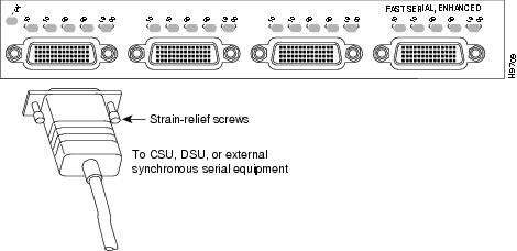

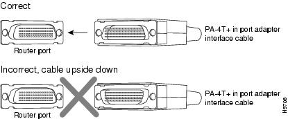
Figure 4-2 Connecting Serial Port Adapter Cables
Step 2 ![]() Attach the network end of the serial cable to your DSU, CSU, DTE, or other external synchronous serial equipment and tighten the strain-relief screws.
Attach the network end of the serial cable to your DSU, CSU, DTE, or other external synchronous serial equipment and tighten the strain-relief screws.
This completes the procedure for attaching serial interface cables to the PA-4T+.
Determining the Port Mode
The port adapter cable connected to each port determines the electrical interface type and mode of the port. The default mode of the ports is DCE, which allows you to perform a loopback test on any port without having to attach a port adapter cable. Although DCE is the default, there is no default clock rate set on the interfaces. When there is no cable attached to a port, the software actually identifies the port as Universal (cable unattached) rather than either a DTE or DCE interface.
Following is an example of the show controllers command for Cisco 7100 series routers, Cisco 7200 series routers, Cisco uBR7200 series routers, Cisco 7201 routers, Cisco 7301 routers, or Cisco 7401ASR routers that shows an interface port (1/0) that has an EIA/TIA-232 DCE cable attached:
Router# show controllers serial 1/0
M4T: show controller:
PAS unit 8, subunit 0, f/w version 1-25, rev ID 0x2800001, version 2
idb = 0x60B83B40, ds = 0x60B858B8, ssb=0x60B85FFC
Clock mux=0x0, ucmd_ctrl=0x1C, port_status=0x3E
Serial config=0x0, line config=0x200
maxdgram=1524, bufpool=48Kb, 96 particles
DCD=up DSR=up DTR=up RTS=up CTS=up
line state: up
cable type : V.24 (RS-232) DCE cable, received clockrate 9600
[display text omitted]
Note ![]() In the above output from the show controllers command, the PA-4T+ is displayed as M4T.
In the above output from the show controllers command, the PA-4T+ is displayed as M4T.
Following is an example of the show controllers cbus command for a VIP that shows an interface port (3/1/0) that has an EIA/TIA-232 DTE cable attached:
Router# show controllers cbus 3/1/0
slot3: VIP2, hw 2.3, sw 21.40, ccb 5800FF30, cmdq 48000088, vps 8192
software loaded from system
IOS (tm) VIP Software (SVIP-DW-M), Version 11.1(8)CA, RELEASED SOFTWARE
ROM Monitor version 17.0
Mx Serial(4), HW Revision 0x2, FW Revision 1.25
Serial3/1/0, applique is RS-232 DTE
gfreeq 48000140, lfreeq 480001D0 (1536 bytes), throttled 0
rxlo 4, rxhi 81, rxcurr 1, maxrxcurr 2
txq 48001A00, txacc 48001A02 (value 6), txlimit 6
Following is an example of the show controllers cbus command for a Catalyst RSM/VIP2 that shows an interface port (1/0) that has an EIA/TIA-232 DTE cable attached:
Router# show controllers cbus 1/0
slot1: VIP2, hw 2.3, sw 21.40, ccb 5800FF30, cmdq 48000088, vps 8192
software loaded from system
IOS (tm) VIP Software (SVIP-DW-M), Version 11.1(8)CA, RELEASED SOFTWARE
ROM Monitor version 17.0
Mx Serial(4), HW Revision 0x2, FW Revision 1.25
Serial3/1/0, applique is RS-232 DTE
gfreeq 48000140, lfreeq 480001D0 (1536 bytes), throttled 0
rxlo 4, rxhi 81, rxcurr 1, maxrxcurr 2
txq 48001A00, txacc 48001A02 (value 6), txlimit 6
Note ![]() The slot values displayed by some commands (such as show diag and show controllers cbus) are not relevant to any physical connection; disregard these slot values for the Catalyst RSM/VIP2.
The slot values displayed by some commands (such as show diag and show controllers cbus) are not relevant to any physical connection; disregard these slot values for the Catalyst RSM/VIP2.
To change the mode of a port online, use software commands to shut down the interface, replace the compact serial cable, restart the interface and, if necessary, reconfigure the port for the new interface. At system startup or restart, the system polls the interfaces and determines the electrical interface type of each port (according to the type of compact serial cable attached). However, the system does not necessarily repoll an interface when you change the adapter cable online. To ensure that the system recognizes the new interface type, shut down and reenable the interface after changing the cable.
If you are replacing a cable with a cable that has the same mode, these steps are not necessary (simply replace the cable without interrupting operation).
Step 1 ![]() Enter configuration mode and at the privileged level of the EXEC (also called enable mode), specify the port address, shut down the interface, and write the configuration to nonvolatile random-access memory (NVRAM). (See the "Using the EXEC Command Interpreter" section for an explanation of the privileged level of the EXEC.) Add additional configuration commands, as needed, before you exit from configuration mode (before you press Ctrl-Z or enter end).
Enter configuration mode and at the privileged level of the EXEC (also called enable mode), specify the port address, shut down the interface, and write the configuration to nonvolatile random-access memory (NVRAM). (See the "Using the EXEC Command Interpreter" section for an explanation of the privileged level of the EXEC.) Add additional configuration commands, as needed, before you exit from configuration mode (before you press Ctrl-Z or enter end).
For the Cisco 7100 series routers, Cisco 7200 series routers, Cisco uBR7200 series routers, Cisco 7201 router, Cisco 7301 router, or Cisco 7401ASR router use the following commands:
Router> enable
Password:
Router# configure terminal
Enter configuration commands, one per line. End with CNTL/Z.
Router(config)# interface serial 1/0
Router(config-if)# shutdown
Ctrl-Z
Router#
For a VIP, use the following commands:
Router> enable
Password:
Router# configure terminal
Enter configuration commands, one per line. End with CNTL/Z.
Router(config)# interface serial 3/1/0
Router(config-if)# shutdown
Ctrl-Z
Router#
For a Catalyst 6000 family FlexWAN module, use the following commands:
Router# configure terminal
Enter configuration commands, one per line. End with CNTL/Z.
Router(config)#
Router(config)# interface serial 3/0/0
Router(config-if)# shutdown
Ctrl-Z
Router#
For a Catalyst RSM/VIP2, use the following commands:
Router> enable
Password:
Router# configure terminal
Enter configuration commands, one per line. End with CNTL/Z.
Router(config)# interface serial 1/0
Router(config-if)# shutdown
Ctrl-Z
Router#
Step 2 ![]() Locate and remove the adapter cable to be replaced.
Locate and remove the adapter cable to be replaced.
Step 3 ![]() Connect the new cable between the PA-4T+ and the network connection. Tighten the thumbscrews at both ends of the cable to secure it in the ports.
Connect the new cable between the PA-4T+ and the network connection. Tighten the thumbscrews at both ends of the cable to secure it in the ports.
Step 4 ![]() Enter configuration mode again, bring the port back up, and save the running configuration to NVRAM.
Enter configuration mode again, bring the port back up, and save the running configuration to NVRAM.
For the Cisco 7100 series routers, Cisco 7200 series routers, Cisco uBR7200 series router,s Cisco 7201 router, Cisco 7301 router, or Cisco 7401ASR router use the following commands:
Router# configure terminal
Enter configuration commands, one per line. End with CNTL/Z.
Router(config)# interface serial 1/0
Router(config-if)# no shutdown
Ctrl-Z
Router#
Router# copy running-config startup-config
For a VIP, use the following commands:
Router# configure terminal
Enter configuration commands, one per line. End with CNTL/Z.
Router(config)# interface serial 3/1/0
Router(config-if)# no shutdown
Ctrl-Z
Router#
Router# copy running-config startup-config
For a Catalyst 6000 family FlexWAN module, use the following commands:
Router# configure terminal
Enter configuration commands, one per line. End with CNTL/Z.
Router(config)# interface serial 3/0/0
Router(config-if)# no shutdown
Ctrl-Z
Router#
Router# copy running-config startup-config
For a Catalyst RSM/VIP2, use the following commands:
Router# configure terminal
Enter configuration commands, one per line. End with CNTL/Z.
Router(config)# interface serial 1/0
Router(config-if)# no shutdown
Ctrl-Z
Router#
Router# copy running-config startup-config
These steps will prompt the system to poll the interface and recognize the new interface immediately.
When you configure a port for a DCE interface for the first time, or when you set up a loopback test, you must set the clock rate for the port. When you connect a DCE cable to a port, the interface will remain down, the clock LEDs will remain off, and the interface will not function until you set a clock rate (regardless of the DCE mode default).
If you are changing the mode of the interface from DCE to DTE, you do not need to change the clock rate for the port. After you replace the DCE cable with a DTE cable and the system recognizes the interface as a DTE, it will use the external clock signal from the remote DCE device and ignore the internal clock signal that the DCE interface normally uses. Therefore, after you configure the clock rate on a port for either a DCE interface or loopback, you can leave the clock rate configured and still use that port as a DTE interface.
This completes the procedure for replacing a port adapter cable on the PA-4T+. Proceed to "Configuring the PA-4T+ Interfaces," to configure the interfaces on your PA-4T+.
 Feedback