Preparing for Installation
This chapter describes the general equipment, safety, and site preparation requirements for installing the PA-POS-1OC3. This chapter contains the following sections:
•![]() Software and Hardware Requirements
Software and Hardware Requirements
•![]() Checking Hardware and Software Compatibility
Checking Hardware and Software Compatibility
Required Tools and Equipment
You need the following tools and parts to install the PA-POS-1OC3. If you need additional equipment, contact a service representative for ordering information.
•![]() PA-POS-1OC3, or PA-POS-1OC3=
PA-POS-1OC3, or PA-POS-1OC3=
•![]() One LC-type duplex or two LC-type simplex, multimode, or single-mode optical fiber cables to connect the interface with the network. (Single-mode and multimode optical fiber cables for the PA-POS-1OC3 are not available from Cisco Systems but are available from commercial cable vendors. For information about optical fiber cables, see the "OC-3 Optical Fiber Specifications" section on page 1-4 and the "Cables and Connectors" section on page 1-7.)
One LC-type duplex or two LC-type simplex, multimode, or single-mode optical fiber cables to connect the interface with the network. (Single-mode and multimode optical fiber cables for the PA-POS-1OC3 are not available from Cisco Systems but are available from commercial cable vendors. For information about optical fiber cables, see the "OC-3 Optical Fiber Specifications" section on page 1-4 and the "Cables and Connectors" section on page 1-7.)
•![]() Phillips screwdriver (1 or 2)
Phillips screwdriver (1 or 2)
•![]() Your own electrostatic discharge (ESD)-prevention equipment or the disposable grounding wrist strap included with all upgrade kits, field-replaceable units (FRUs), and spares
Your own electrostatic discharge (ESD)-prevention equipment or the disposable grounding wrist strap included with all upgrade kits, field-replaceable units (FRUs), and spares
•![]() Antistatic mat
Antistatic mat
•![]() Antistatic container
Antistatic container
Software and Hardware Requirements
Table 2-1 lists the minimum Cisco IOS software release required to use the PA-POS-1OC3 in supported router or switch platforms.

Note ![]() The PA-POS-1OC3 is considered a high-bandwidth port adapter. Traffic from multiple PA-POS-1OC3 network interfaces could theoretically exceed the bandwidth of the CxBus or CyBus. This would cause packets to be dropped.
The PA-POS-1OC3 is considered a high-bandwidth port adapter. Traffic from multiple PA-POS-1OC3 network interfaces could theoretically exceed the bandwidth of the CxBus or CyBus. This would cause packets to be dropped.
Cisco 7200 VXR Routers
Cisco 7200 VXR routers have certain data-carrying capacity (or bandwidth) restrictions that affect the number of high-bandwidth, medium-bandwidth, and low-bandwidth port adapters you can install. Refer to the Cisco 7200 Series Port Adapter Hardware Configuration Guidelines for more information on port adapter installation restrictions.
The PA-POS-1OC3 is supported on Cisco 7200 VXR routers with network processing services engine NSE-1, and network processing engines NPE-400 and forward.
For all systems in which you install the PA-POS-1OC3, use the show version command to display the current configuration of the router or switch, including the system software version that is currently loaded and running. Use the show diag slot command to view specific information about the hardware installed in your system.
Cisco 7201 Router
The PA-POS-1OC3 port adapter is installed in the single port adapter slot of the Cisco 7201 router.
Cisco 7301 Router
The PA-POS-1OC3 port adapter is installed in the single port adapter slot of the Cisco 7301 router.
Cisco 7401ASR Router
The PA-POS-1OC3 port adapter is installed in the single port adapter slot of the Cisco 7401ASR router.
Cisco 7500 Series Routers
The PA-POS-1OC3 port adapter is supported with the RSP4+, RSP8, and RSP16, and the VIP4-50, VIP4-80,and VIP6-80.
Cisco 7600 Series Routers
The Cisco PA-POS-1OC3 port adapters can be installed on FlexWAN or Enhanced FlexWAN modules in slots 2 through 6 or 9. If either slot 7 or slot 8 does not have a supervisor engine in it, that slot is also available.
Checking Hardware and Software Compatibility
To check the minimum software requirements of Cisco IOS software with the hardware installed on your router, Cisco maintains the Software Advisor tool on Cisco.com. This tool does not verify whether modules within a system are compatible, but it does provide the minimum Cisco IOS requirements for individual hardware modules or components.
Note ![]() Access to this tool is limited to users with Cisco.com login accounts.
Access to this tool is limited to users with Cisco.com login accounts.
To access Software Advisor, click Login at Cisco.com and go to Support > Tools and Resources > Software Advisor. You can also access the tool by pointing your browser directly to http://www.cisco.com/en/US/support/tsd_most_requested_tools.html.
Choose a product family or enter a specific product number to search for the minimum supported software release needed for your hardware.
Safety Guidelines
This section provides safety guidelines that you should follow when working with any equipment that connects to electrical power or telephone wiring.
Safety Warnings
Safety warnings appear throughout this publication in procedures that, if performed incorrectly, may harm you. A warning symbol precedes each warning statement.
Warning Definition


Electrical Equipment Guidelines
Follow these basic guidelines when working with any electrical equipment:
•![]() Before beginning any procedures requiring access to the chassis interior, locate the emergency power-off switch for the room in which you are working.
Before beginning any procedures requiring access to the chassis interior, locate the emergency power-off switch for the room in which you are working.
•![]() Disconnect all power and external cables before moving a chassis.
Disconnect all power and external cables before moving a chassis.
•![]() Do not work alone if potentially hazardous conditions exist.
Do not work alone if potentially hazardous conditions exist.
•![]() Never assume that power has been disconnected from a circuit; always check.
Never assume that power has been disconnected from a circuit; always check.
•![]() Do not perform any action that creates a potential hazard to people or makes the equipment unsafe. Carefully examine your work area for possible hazards such as moist floors, ungrounded power extension cables, and missing safety grounds.
Do not perform any action that creates a potential hazard to people or makes the equipment unsafe. Carefully examine your work area for possible hazards such as moist floors, ungrounded power extension cables, and missing safety grounds.
Telephone Wiring Guidelines
Use the following guidelines when working with any equipment that is connected to telephone wiring or to other network cabling:
•![]() Never install telephone wiring during a lightning storm.
Never install telephone wiring during a lightning storm.
•![]() Never install telephone jacks in wet locations unless the jack is specifically designed for wet locations.
Never install telephone jacks in wet locations unless the jack is specifically designed for wet locations.
•![]() Never touch uninsulated telephone wires or terminals unless the telephone line has been disconnected at the network interface.
Never touch uninsulated telephone wires or terminals unless the telephone line has been disconnected at the network interface.
•![]() Use caution when installing or modifying telephone lines.
Use caution when installing or modifying telephone lines.
Preventing Electrostatic Discharge Damage
Electrostatic discharge (ESD) damage, which can occur when electronic cards or components are improperly handled, results in complete or intermittent failures. Port adapters and processor modules consist of printed circuit boards that are fixed in metal carriers. Electromagnetic interference (EMI) shielding and connectors are integral components of the carrier. Although the metal carrier helps to protect the board from ESD, use a preventive antistatic strap during handling.
Following are guidelines for preventing ESD damage:
•![]() Always use an ESD wrist or ankle strap and ensure that it makes good skin contact.
Always use an ESD wrist or ankle strap and ensure that it makes good skin contact.
•![]() Connect the equipment end of the strap to an unfinished chassis surface.
Connect the equipment end of the strap to an unfinished chassis surface.
•![]() When installing a component, use any available ejector levers or captive installation screws to properly seat the bus connectors in the backplane or midplane. These devices prevent accidental removal, provide proper grounding for the system, and help to ensure that bus connectors are properly seated.
When installing a component, use any available ejector levers or captive installation screws to properly seat the bus connectors in the backplane or midplane. These devices prevent accidental removal, provide proper grounding for the system, and help to ensure that bus connectors are properly seated.
•![]() When removing a component, use any available ejector levers or captive installation screws to release the bus connectors from the backplane or midplane.
When removing a component, use any available ejector levers or captive installation screws to release the bus connectors from the backplane or midplane.
•![]() Handle carriers by available handles or edges only; avoid touching the printed circuit boards or connectors.
Handle carriers by available handles or edges only; avoid touching the printed circuit boards or connectors.
•![]() Place a removed component board-side-up on an antistatic surface or in a static shielding container. If you plan to return the component to the factory, immediately place it in a static shielding container.
Place a removed component board-side-up on an antistatic surface or in a static shielding container. If you plan to return the component to the factory, immediately place it in a static shielding container.
•![]() Avoid contact between the printed circuit boards and clothing. The wrist strap only protects components from ESD voltages on the body; ESD voltages on clothing can still cause damage.
Avoid contact between the printed circuit boards and clothing. The wrist strap only protects components from ESD voltages on the body; ESD voltages on clothing can still cause damage.
•![]() Never attempt to remove the printed circuit board from the metal carrier.
Never attempt to remove the printed circuit board from the metal carrier.

Laser Safety
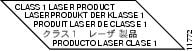
The multimode aperture has a Class 1 laser warning label, as shown in Figure 2-1.
Figure 2-1 Class 1 Laser Product Warning Label on the PA-POS-1OC3

Warning ![]() Class 1 laser product. Statement 1008
Class 1 laser product. Statement 1008
Warning ![]() Invisible laser radiation may be emitted from disconnected fibers or connectors. Do not stare into beams or view directly with optical instruments. Statement 1051
Invisible laser radiation may be emitted from disconnected fibers or connectors. Do not stare into beams or view directly with optical instruments. Statement 1051
FCC Class A Compliance
This equipment has been tested and found to comply with the limits for a Class A digital device, pursuant to part 15 of the FCC rules. These limits are designed to provide reasonable protection against harmful interference when the equipment is operated in a commercial environment. This equipment generates, uses, and can radiate radio-frequency energy and, if not installed and used in accordance with the instruction manual, may cause harmful interference to radio communications. Operation of this equipment in a residential area is likely to cause harmful interference, in which case users will be required to correct the interference at their own expense.
You can determine whether your equipment is causing interference by turning it off. If the interference stops, it was probably caused by the Cisco equipment or one of its peripheral devices. If the equipment causes interference to radio or television reception, try to correct the interference by using one or more of the following measures:
•![]() Turn the television or radio antenna until the interference stops.
Turn the television or radio antenna until the interference stops.
•![]() Move the equipment to one side or the other of the television or radio.
Move the equipment to one side or the other of the television or radio.
•![]() Move the equipment farther away from the television or radio.
Move the equipment farther away from the television or radio.
•![]() Plug the equipment into an outlet that is on a different circuit from the television or radio. (That is, make certain the equipment and the television or radio are on circuits controlled by different circuit breakers or fuses.)
Plug the equipment into an outlet that is on a different circuit from the television or radio. (That is, make certain the equipment and the television or radio are on circuits controlled by different circuit breakers or fuses.)
 Feedback