- Title and copyright: PA-2H Dual-Port HSSI Port Adapter Installation and Configuration
- Preface: PA-2H Dual-Port HSSI Port Adapter Installation and Configuration
- Overview: PA-2H Dual-Port HSSI Port Adapter Installation and Configuration
- Preparing to Install the PA-2H Dual-Port HSSI Port Adapter
- Removing and Installing the PA-2H Dual-Port HSSI Port Adapter
- Configuring the PA-2H Dual-Port HSSI Port Adapter
- Port Adapter Overview
- Interface Specifications
- LEDs
- Cables, Connectors, and Pinouts
- Port Adapter Slot Locations on the Supported Platforms
- Catalyst RSM/VIP2 Slot Numbering
- Catalyst 6000 Family FlexWAN Module Slot Numbering
- Cisco 7100 Series Routers Slot Numbering
- Cisco 7200 Series and Cisco uBR7200 Series Routers Slot Numbering
- Cisco 7301 Router Slot Numbering
- Cisco 7304 PCI Port Adapter Carrier Card Slot Numbering
- Cisco 7401ASR Router Slot Numbering
- VIP Slot Numbering
- Identifying Interface Addresses
- Catalyst RSM/VIP2 Interface Addresses
- Catalyst 6000 Family FlexWAN Module Interface Addresses
- Cisco 7100 Series Routers Interface Addresses
- Cisco 7200 Series and Cisco uBR7200 Series Routers Interface Addresses
- Cisco 7301 Router Interface Addresses
- Cisco 7304 PCI Port Adapter Carrier Card Interface Addresses
- Cisco 7401ASR Router Interface Addresses
- VIP Interface Addresses
Overview
This chapter describes the PA-2H port adapter and contains the following sections:
•![]() LEDs
LEDs
•![]() Cables, Connectors, and Pinouts
Cables, Connectors, and Pinouts
•![]() Port Adapter Slot Locations on the Supported Platforms
Port Adapter Slot Locations on the Supported Platforms
•![]() Identifying Interface Addresses
Identifying Interface Addresses
Port Adapter Overview
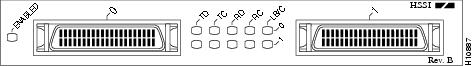
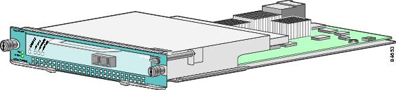
The PA-2H dual-port HSSI port adapter (PA-2H, Rev. B), shown in Figure 1-1, provides two high-speed serial interfaces. The interfaces on the PA-2H are considered to be data terminal equipment (DTE) devices. (Port adapters have a handle attached, but this handle is occasionally not shown in figures in this document to allow a full view of detail on the port adapter faceplate.)
Figure 1-1 PA-2H—Faceplate View
The HSSI network interfaces reside on modular port adapters, which provide a direct connection between the high-speed bus in the router or switch and the external networks.

Note ![]() The Catalyst RSM/VIP2, the Catalyst 6000 family FlexWAN module, the VIP, and the Cisco 7304 PCI Port Adapter Carrier Card support online insertion and removal (OIR), but individual port adapters do not. To replace port adapters you must first remove the Catalyst RSM/VIP2, the Catalyst 6000 family FlexWAN module, the VIP, or the Cisco 7304 PCI Port Adapter Carrier Card from the chassis and then replace port adapters as required.
The Catalyst RSM/VIP2, the Catalyst 6000 family FlexWAN module, the VIP, and the Cisco 7304 PCI Port Adapter Carrier Card support online insertion and removal (OIR), but individual port adapters do not. To replace port adapters you must first remove the Catalyst RSM/VIP2, the Catalyst 6000 family FlexWAN module, the VIP, or the Cisco 7304 PCI Port Adapter Carrier Card from the chassis and then replace port adapters as required.
The Cisco 7200 series, the Cisco uBR7246 routers, the Cisco 7301 routers, and Cisco 7401ASR routers support the OIR of all port adapter types.
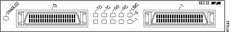
The newest dual-port PA-2H can be identified by Rev. B in the lower right corner of its front-panel label (see Figure 1-1). The older dual-port PA-2H does not have Rev. B on its label (see Figure 1-2).
Figure 1-2 Older PA-2H—Pre-Rev. B—Faceplate View
To determine which PA-2H model you currently have installed, examine the front-panel label, or use the show diag command. (For information on using the show diag command, see "Configuring the PA-2H.")
Note ![]() You should replace older PA-2H port adapters with the newer PA-2H Rev. B port adapter. Contact Cisco's Technical Assistance Center (TAC) for replacement details. (For information on the TAC, see the "Obtaining Documentation" section.)
You should replace older PA-2H port adapters with the newer PA-2H Rev. B port adapter. Contact Cisco's Technical Assistance Center (TAC) for replacement details. (For information on the TAC, see the "Obtaining Documentation" section.)
Interface Specifications
The PA-2H conforms to the BABT/TC/130, EIA/TIA-612, and EIA/TIA-613 standards for HSSI. The PA-2H provides two interfaces. Each interface provides a full-duplex high-speed synchronous serial interface (HSSI) for transmitting and receiving data at rates of up to 52 megabits per second (Mbps).
The HSSI, which has been standardized as EIA/TIA 612/613, provides access to services at T3 (45 Mbps), E3 (34 Mbps), and Synchronous Optical Network (SONET) STS-1 (51.82 Mbps) rates. The actual rate of the interface depends on the external DSU and the type of service to which it is connected.
Each HSSI port on the PA-2H is a female 50-pin SCSI-II-type receptacle. You must use an HSSI interface cable from Cisco Systems to connect the interface to an external data service unit (DSU). See the "Cables, Connectors, and Pinouts" section for descriptions of HSSI cables.
The PA-2H supports both 16- and 32-bit cyclic redundancy checks (CRCs). The default is 16-bit CRCs; to enable 32-bit CRCs, you use a configuration command. (For a description of the CRC function, see "Configuring the PA-2H.")
LEDs
The PA-2H has two rows of five status LEDs (one row of five for each HSSI port) and one enabled LED. (See Figure 1-3.) The green- and amber-colored LED for each port indicates port status.
Figure 1-3 LEDs on the PA-2H—Partial Front View
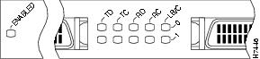
After system initialization, the enabled LED goes on to indicate that the port adapter has been enabled for operation.
The following conditions must be met before the PA-2H is enabled:
•![]() The port adapter is correctly connected to the backplane and receiving power in Cisco 7000 series and Cisco 7500 series routers, the Catalyst 5000 family switches, the Catalyst 6000 family switches, or to the midplane and receiving power in Cisco 7200 series and Cisco uBR7200 series routers.
The port adapter is correctly connected to the backplane and receiving power in Cisco 7000 series and Cisco 7500 series routers, the Catalyst 5000 family switches, the Catalyst 6000 family switches, or to the midplane and receiving power in Cisco 7200 series and Cisco uBR7200 series routers.
•![]() The bus recognizes the port adapter or HSSI-equipped Catalyst RSM/VIP2, Catalyst 6000 family FlexWAN module, the VIP, or the Cisco 7304 PCI Port Adapter Carrier Card.
The bus recognizes the port adapter or HSSI-equipped Catalyst RSM/VIP2, Catalyst 6000 family FlexWAN module, the VIP, or the Cisco 7304 PCI Port Adapter Carrier Card.
•![]() The system recognizes the PA-2H, VIP with a PA-2H, a Catalyst RSM/VIP2 with a PA-2H, the Catalyst 6000 family FlexWAN module with a PA-2H, or the Cisco 7304 PCI Port Adapter Carrier Card with a PA-2H.
The system recognizes the PA-2H, VIP with a PA-2H, a Catalyst RSM/VIP2 with a PA-2H, the Catalyst 6000 family FlexWAN module with a PA-2H, or the Cisco 7304 PCI Port Adapter Carrier Card with a PA-2H.
If any of the above conditions are not met, or if the initialization fails for other reasons, the enabled LED does not go on.
Table 1-1 lists LED colors and indications.
Cables, Connectors, and Pinouts
This section provides information about the HSSI cables you should use with the PA-2H. Two types of cables are available for use with the PA-2H: the HSSI interface cable used to connect your router to an external DSU (and HSSI network), and a null modem cable with which you can connect two routers back to back. Both HSSI cables are available only from Cisco systems and conform to EIA/TIA-612 and EIA/TIA-613 specifications.
HSSI Interface Cable
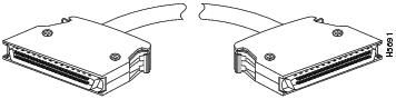
The HSSI cable (CAB-HSI1=) connects the PA-2H with the external DSU. The HSSI cable is 10 feet (3.048 meters) long. The maximum HSSI cable length allowed is 50 feet (15.24 meters). Figure 1-4 shows the HSSI cable and the 50-pin connector used at each end of the HSSI cable. For connection instructions, see "Removing and Installing Port Adapters." Table 1-2 lists the pinouts.
Figure 1-4 HSSI Interface Cable and Connectors
|
|
|
|
Router DSU |
|---|---|---|---|
SG (signal ground) |
1 |
26 |
— |
RT (receive timing) |
2 |
27 |
<— |
CA (DCE available) |
3 |
28 |
<— |
RD (receive data reserved) |
4 |
29 |
<— |
LC (loopback circuit C) |
5 |
30 |
<— |
ST (send timing) |
6 |
31 |
<— |
SG (signal ground) |
7 |
32 |
— |
TA (DTE available) |
8 |
33 |
—> |
TT (terminal timing) |
9 |
34 |
—> |
LA (loopback circuit A) |
10 |
35 |
—> |
SD (send data) |
11 |
36 |
—> |
LB (loopback circuit B) |
12 |
37 |
— |
SG (signal ground) |
13 |
38 |
—> |
5 (ancillary to DCE) |
14-18 |
39-43 |
— |
SG (signal ground) |
19 |
44 |
<— |
5 (ancillary from DCE) |
20-24 |
45-49 |
— |
SG (signal ground) |
25 |
50 |
— |
1 Router is + side (DTE). DSU is - side (DCE). |
HSSI Null Modem Cable
The null modem cable (CAB-HNUL=) can connect two routers directly back to back. The null modem cable is 10 feet (3.048 meters) long. Figure 1-5 shows the null modem cable. The maximum null modem cable length allowed is 50 feet (15.24 meters). The two routers must be in the same location, and can be two Cisco 7000 series routers, two Cisco 7100 series routers, two Cisco 7200 series routers, two Cisco uBR7200 series routers, two Cisco 7301 routers, two Cisco 7401ASR routers, two Cisco 7304 routers, or two Cisco 7500 series routers, or one of each. With null modem connection, you can verify the operation of the HSSI or link the routers directly in order to build a larger node.
Figure 1-5 Null Modem Cable and Connectors
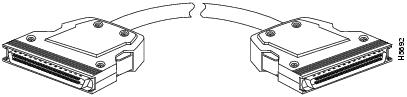
The null modem cable uses the same 50-pin connectors as the HSSI cable, but uses the pinouts listed in Table 1-2. For connection instructions, see "Removing and Installing Port Adapters."

Port Adapter Slot Locations on the Supported Platforms
This section discusses port adapter slot locations on the supported platforms. The illustrations that follow summarize slot location conventions on each platform:
•![]() Catalyst RSM/VIP2 Slot Numbering
Catalyst RSM/VIP2 Slot Numbering
•![]() Catalyst 6000 Family FlexWAN Module Slot Numbering
Catalyst 6000 Family FlexWAN Module Slot Numbering
•![]() Cisco 7100 Series Routers Slot Numbering
Cisco 7100 Series Routers Slot Numbering
•![]() Cisco 7200 Series and Cisco uBR7200 Series Routers Slot Numbering
Cisco 7200 Series and Cisco uBR7200 Series Routers Slot Numbering
•![]() Cisco 7301 Router Slot Numbering
Cisco 7301 Router Slot Numbering
•![]() Cisco 7304 PCI Port Adapter Carrier Card Slot Numbering
Cisco 7304 PCI Port Adapter Carrier Card Slot Numbering
•![]() Cisco 7401ASR Router Slot Numbering
Cisco 7401ASR Router Slot Numbering
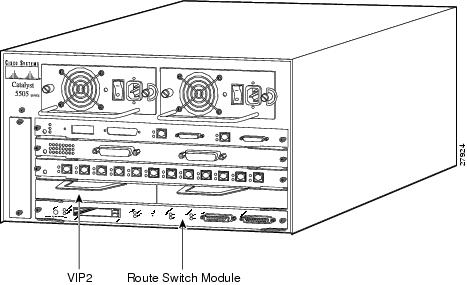
Catalyst RSM/VIP2 Slot Numbering
The Catalyst RSM/VIP2 can be installed in any slot except the top slots, which contain the supervisor engine. The Catalyst RSM/VIP2 in a Catalyst 5000 family switch does not use interface processor slot numbering; therefore, slots are not numbered in Figure 1-6. The PA-2H can be installed into either port adapter slot 0 or slot 1 on a Catalyst RSM/VIP2. Figure 1-6 shows a Catalyst RSM/VIP2 with two port adapters installed.
Note ![]() The Catalyst 5500 switch has 13 slots. Slot 1 is reserved for the supervisor engine. If a redundant supervisor engine is used, it would go in slot 2; otherwise, slot 2 can be used for other modules. Slot 13 is a dedicated slot, reserved for the ATM Switch Processor module. Refer to the Catalyst 5000 Series Route Switch Module Installation and Configuration Note for any additional slot restrictions for the Catalyst RSM/VIP2.
The Catalyst 5500 switch has 13 slots. Slot 1 is reserved for the supervisor engine. If a redundant supervisor engine is used, it would go in slot 2; otherwise, slot 2 can be used for other modules. Slot 13 is a dedicated slot, reserved for the ATM Switch Processor module. Refer to the Catalyst 5000 Series Route Switch Module Installation and Configuration Note for any additional slot restrictions for the Catalyst RSM/VIP2.
Figure 1-6 Catalyst 5000 Family Switch with Port Adapters Installed on Catalyst RSM/VIP2
Note ![]() For additional information, see the "Cisco 7401ASR Router Slot Numbering" section.
For additional information, see the "Cisco 7401ASR Router Slot Numbering" section.
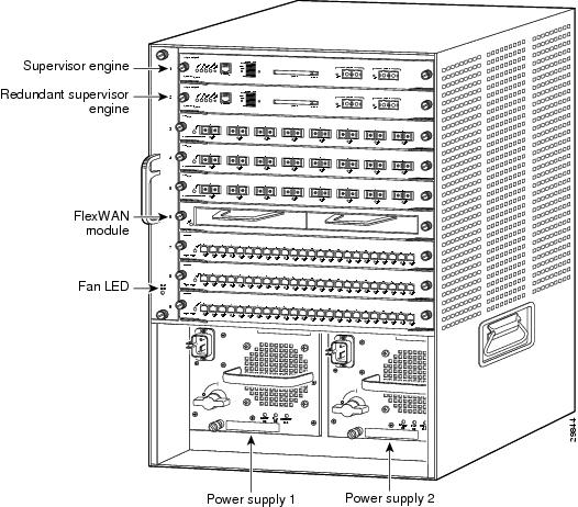
Catalyst 6000 Family FlexWAN Module Slot Numbering
The Catalyst 6000 family FlexWAN module can be installed in any slot except slot 1, which is reserved for the supervisor engine. The PA-2H can be installed into either port adapter bay 0 or bay 1 on a FlexWAN module. Figure 1-7 shows a FlexWAN module with two blank port adapters installed.
Note ![]() Slot 1 is reserved for the supervisor engine. If a redundant supervisor engine is used, it would go in slot 2; otherwise, slot 2 can be used for other modules.
Slot 1 is reserved for the supervisor engine. If a redundant supervisor engine is used, it would go in slot 2; otherwise, slot 2 can be used for other modules.
Figure 1-7 Catalyst 6000 Family Switch with Blank Port Adapters Installed on FlexWAN Module
Cisco 7100 Series Routers Slot Numbering
The PA-2H can be installed in port adapter slot 3 in Cisco 7120 series routers, and in port adapter slot 4 in Cisco 7140 series routers. Figure 1-8 shows a Cisco 7120 with a port adapter installed in slot 3. Figure 1-9 shows a Cisco 7140 with a port adapter installed in slot 4.
Figure 1-8 Port Adapter Slots in the Cisco 7100 Series Router—Cisco 7120 Series
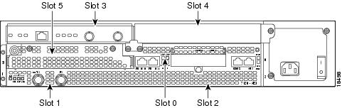
Figure 1-9 Port Adapter Slots in the Cisco 7100 Series Router—Cisco 7140 Series
Cisco 7200 Series and Cisco uBR7200 Series Routers Slot Numbering
Figure 1-10 shows a Cisco 7206 with port adapters installed. In the Cisco 7206 (including the Cisco 7206 and Cisco 7206VXR as router shelves in a Cisco AS5800 Universal Access Server), port adapter slot 1 is in the lower left position, and port adapter slot 6 is in the upper right position. (The Cisco 7204 and Cisco 7204VXR are not shown; however, the PA-2H can be installed in any available port adapter slot.)
Figure 1-10 Port Adapter Slots in the Cisco 7206
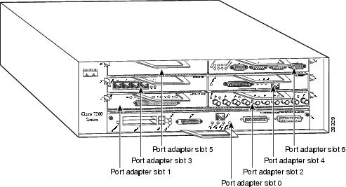
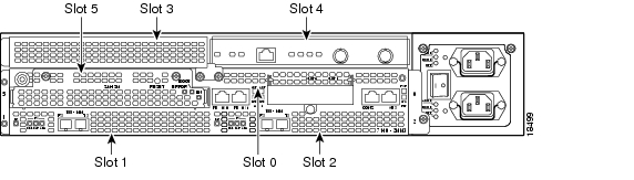
Figure 1-11 shows the slot numbering of port adapters in a Cisco uBR7200 series router. The port adapter slots are numbered slot 1 and slot 2 for the Cisco uBR7246 and Cisco uBR7246 VXR and slot 1 for the Cisco uBR7223. (Slot 0 is always reserved for the Fast Ethernet port on the I/O controller—if present.)
Figure 1-11 Port Adapter Slots in the Cisco uBR7246 and Cisco uBR7246 VXR
Cisco 7301 Router Slot Numbering
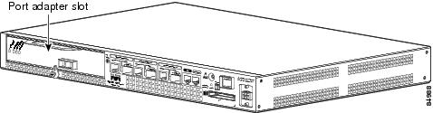
Figure 1-12 shows the front view of a Cisco 7301 router with a port adapter installed. There is only one port adapter slot in a Cisco 7301 router.
Figure 1-12 Cisco 7301 Router with a Port Adapter Installed
Cisco 7304 PCI Port Adapter Carrier Card Slot Numbering
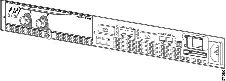
The Cisco 7304 PCI Port Adapter Carrier Card accepts one single-width port adapter. Figure 1-13 shows a Cisco 7304 PCI Port Adapter Carrier Card with a port adapter installed.
Figure 1-13 Cisco 7304 PCI Port Adapter Carrier Card—Port Adapter Installed
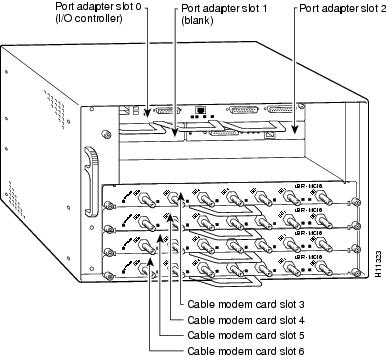
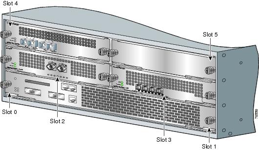
The Cisco 7304 PCI Port Adapter Carrier Card installs in Cisco 7304 router module slots 2 through 5. See Figure 1-14 for module slot numbering on a Cisco 7304 router.
Figure 1-14 Module Slots on the Cisco 7304 Router
Cisco 7401ASR Router Slot Numbering
Figure 1-15 shows the front view of a Cisco 7401ASR router with a port adapter installed. There is only one port adapter slot in a Cisco 7401ASR router.
Figure 1-15 Cisco 7401ASR Router with a Port Adapter Installed
VIP Slot Numbering
Figure 1-16 shows a partial view of a VIP motherboard with installed port adapters. With the motherboard oriented as shown in Figure 1-16, the left port adapter is in port adapter slot 0, and the right port adapter is in port adapter slot 1. The slot numbering is the same for the Catalyst RSM/VIP2. The slots are always numbered 0 and 1.
Figure 1-16 VIP Motherboard with Two Port Adapters—Partial View, Horizontal Orientation
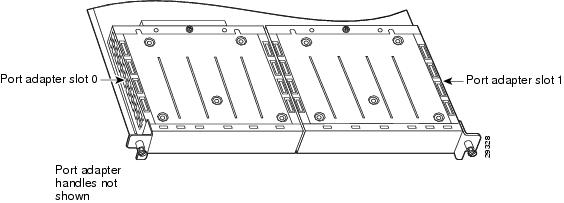
Note ![]() In the Cisco 7000, Cisco 7507, Cisco 7513, and Cisco 7576 chassis, the VIP motherboard is installed vertically. In the Cisco 7010 and Cisco 7505 chassis, the VIP motherboard is installed horizontally.
In the Cisco 7000, Cisco 7507, Cisco 7513, and Cisco 7576 chassis, the VIP motherboard is installed vertically. In the Cisco 7010 and Cisco 7505 chassis, the VIP motherboard is installed horizontally.
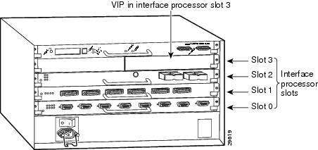
Figure 1-17 shows a VIP installed in an interface processor slot of a Cisco 7505 router.
Figure 1-17 Interface Slot Numbers—Cisco 7505 Shown
Identifying Interface Addresses
This section describes how to identify interface addresses for the PA-2H in supported platforms. Interface addresses specify the actual physical location of each interface on a router or switch.
Interfaces on the PA-2H installed in a router or switch maintain the same address regardless of whether other port adapters are installed or removed. However, when you move a port adapter to a different slot, the first number in the interface address changes to reflect the new port adapter slot number.
Interfaces on a PA-2H installed in a VIP maintain the same address regardless of whether other interface processors are installed or removed. However, when you move a VIP to a different slot, the interface processor slot number changes to reflect the new interface processor slot.
Note ![]() Interface ports are numbered from left to right starting with 0.
Interface ports are numbered from left to right starting with 0.
Table 1-4 explains how to identify interface addresses.
|
|
|
|
|
|---|---|---|---|
Catalyst RSM/VIP2 in |
Port-adapter-slot-number/interface-port-number |
Port adapter slot—always 0 or 1 Interface port—0 and 1 |
0/1 |
Catalyst 6000 family FlexWAN module in Catalyst 6000 family switches |
Module-slot-number/port-adapter-bay-number/ |
Module slot number—21 through 6 or 9 (depending on the number of slots in the switch) Port adapter bay—always 0 or 1 Interface port—0 and 1 |
3/0/0 |
Cisco 7120 series routers |
Port-adapter-slot-number/interface-port-number |
Port adapter slot—always 3 Interface port—0 and 1 |
3/1 |
Cisco 7140 series routers |
Port-adapter-slot-number/interface-port-number |
Port adapter slot—always 4 Interface port—0 and 1 |
4/0 |
Cisco 7200 series routers |
Port-adapter-slot-number/interface-port-number |
Port adapter slot—0 through 6 (depends on the number of slots in the router)2 Interface port—0 and 1 |
1/0 |
Cisco uBR7223 router |
Port-adapter-slot-number/interface-port-number |
Port adapter slot—always 12 Interface port—0 and 1 |
1/0 |
Cisco uBR7246 and Cisco uBR7246 VXR routers |
Port-adapter-slot-number/interface-port-number |
Port adapter slot—always 1 or 22 Interface port—0 and 1 |
1/2 |
Cisco 7301 router |
Port-adapter-slot-number/interface-port-number |
Port adapter slot—always 1 Interface port—0 and 1 |
1/1 |
Cisco 7304 PCI Port Adapter Carrier Card in Cisco 7304 routers |
Port-adapter-slot-number/interface-port-number |
Port adapter slot—router module slot 2 through 5 Interface port—0 and 1 |
3/0 |
Cisco 7401ASR routers |
Port-adapter-slot-number/interface-port-number |
Port adapter slot—always 1 Interface port—0 and 1 |
1/1 |
VIP in Cisco 7000 series or Cisco 7500 series routers |
Interface-processor-slot-number/ port-adapter-slot-number/interface-port-number |
Interface processor slot—0 through 12 (depends on the number of slots in the router) Port adapter slot—always 0 or 1 Interface port—0 and 1 |
3/1/0 |
1 Slot 1 is reserved for the supervisor engine. If a redundant supervisor engine is used, it must go in slot 2; otherwise, slot 2 can be used for other modules. 2 Port adapter slot 0 is reserved for the Fast Ethernet port on the I/O controller (if present). |
Catalyst RSM/VIP2 Interface Addresses
This section describes how to identify the interface addresses used for the PA-2H on the Catalyst RSM/VIP2 in Catalyst 5000 family switches. The interface address is composed of a two-part number in the format port-adapter-slot-number/interface-port number.
See Table 1-4 for the interface address format.
Catalyst 6000 Family FlexWAN Module Interface Addresses
This section describes how to identify the interface addresses used for the PA-2H on the Catalyst FlexWAN module in the Catalyst 6000 family switches.The interface address is composed of a three-part number in the format module-number/port-adapter-bay-number/interface-port-number.
See Table 1-4 for the interface address format.
If the FlexWAN module is inserted in module slot 3, then the interface addresses of the PA-2H are 3/0/0 and 3/0/1 (module slot 3, port adapter bay 0, and interfaces 0 and 1). If the port adapter was in port adapter bay 1 on the FlexWAN module, these same interface addresses would be numbered 3/1/0 and 3/1/1.
Note ![]() If you remove the FlexWAN module with the PA-2H from module slot 3 and install it in module slot 6, the interface addresses become 6/0/0 and 6/0/1.
If you remove the FlexWAN module with the PA-2H from module slot 3 and install it in module slot 6, the interface addresses become 6/0/0 and 6/0/1.
Note ![]() The FlexWAN module physical port address begins with slot 0, which differs from the conventional Catalyst 6000 family port address, which begins with slot 1.
The FlexWAN module physical port address begins with slot 0, which differs from the conventional Catalyst 6000 family port address, which begins with slot 1.
Cisco 7100 Series Routers Interface Addresses
This section describes how to identify the interface addresses used for the PA-2H in Cisco 7100 series routers. The interface address is composed of a two-part number in the format port-adapter-slot-number/interface-port-number. See Table 1-4 for the interface address format.
Cisco 7200 Series and Cisco uBR7200 Series Routers Interface Addresses
This section describes how to identify the interface addresses used for the PA-2H in Cisco 7200 series routers or Cisco uBR700 series routers. The interface address is composed of a two-part number in the format port-adapter-slot-number/interface-port-number. See Table 1-4 for the interface address format.
In Cisco 7200 series routers, port adapter slots are numbered from the lower left to the upper right, beginning with port adapter slot 1 and continuing through port adapter slot 2 for the Cisco 7202, slot 4 for the Cisco 7204 and Cisco 7204VXR, and slot 6 for the Cisco 7206 and Cisco 7206VXR. (Port adapter slot 0 is reserved for the optional Fast Ethernet port on the I/O controller—if present.)
The interface addresses of the interfaces on the PA-2H in port adapter slot 1 are 1/0 and 1/1 (port adapter slot 1 and interfaces 0 and 1). If the PA-2H was in port adapter slot 4, these same interfaces would be numbered 4/0 and 4/1 (port adapter slot 4 and interfaces 0 and 1).
In Cisco uBR7200 series routers, port adapter slots are numbered slot 1 and slot 2 for the Cisco uBR7246 and Cisco uBR7246 VXR and slot 1 for the Cisco uBR7223. (Slot 0 is always reserved for the Fast Ethernet port on the I/O controller—if present.) The individual interfaces always begin with 0. The number of additional interfaces depends on the number of interface ports on a port adapter.
The interface addresses of the interfaces on a PA-2H in port adapter slot 2 of a Cisco uBR7246 or Cisco uBR7246 VXR are 2/0 and 2/1 (port adapter slot 2 and interfaces 0 and 1). If the PA-2H was in port adapter slot 1, these same interfaces would be numbered 1/0 and 1/1 (port adapter slot 1 and interfaces 0 and 1).
Cisco 7301 Router Interface Addresses
This section describes how to identify the interface addresses for the PA-2H in a Cisco 7301 router. In the Cisco 7301 router, slot 1 is the port adapter slot you use for the PA-2H. (See Figure 1-12.) The interface address is composed of a two-part number in the format port-adapter-slot-number/interface-port-number. See Table 1-4 for the interface address format.
Cisco 7304 PCI Port Adapter Carrier Card Interface Addresses
This section describes how to identify the interface addresses used for the PA-2H in the Cisco 7304 PCI Port Adapter Carrier Card in Cisco 7304 routers. The interface address is made of a two-part number in the format port-adapter-slot-number/interface-port-number.
The Cisco 7304 PCI Port Adapter Carrier Card installs into Cisco 7304 router module slots 2 through 5 (See Figure 1-14.) The port-adapter-slot-number is the Cisco 7304 router module slot number. For example, the interface address of port 0 on a PA-2H, in which the Cisco 7304 PCI Port Adapter Carrier Card is installed in Cisco 7304 router module slot 3, would be numbered 3/0.
Cisco 7401ASR Router Interface Addresses
This section describes how to identify the interface addresses for the PA-2H in a Cisco 7401ASR router. In the Cisco 7401ASR router, slot 1 is the port adapter slot you use for the PA-2H. (See Figure 1-15.) The interface address is composed of a two-part number in the format port-adapter-slot-number/interface-port-number. See Table 1-4 for the interface address format.
VIP Interface Addresses
This section describes how to identify the interface addresses used for the PA-2H on a VIP in Cisco 7000 series and Cisco 7500 series routers.
Note ![]() Although the processor slots in the 7-slot Cisco 7000 and Cisco 7507 and 13-slot Cisco 7513 and Cisco 7576 are vertically oriented and those in the 5-slot Cisco 7010 and Cisco 7505 are horizontally oriented, all Cisco 7000 series and Cisco 7500 series routers use the same method for slot and port numbering.
Although the processor slots in the 7-slot Cisco 7000 and Cisco 7507 and 13-slot Cisco 7513 and Cisco 7576 are vertically oriented and those in the 5-slot Cisco 7010 and Cisco 7505 are horizontally oriented, all Cisco 7000 series and Cisco 7500 series routers use the same method for slot and port numbering.
See Table 1-4 for the interface address format. The interface address is composed of a three-part number in the format interface-processor-slot-number/port-adapter-slot-number/interface-port-number.
If the VIP is inserted in interface processor slot 3, then the interface addresses of the PA-2H are 3/1/0 and 3/1/1 (interface processor slot 3, port adapter slot 1, and interfaces 0 and 1). If the PA-2H was in port adapter slot 0 on the VIP, these same interface addresses would be numbered 3/0/0 and 3/0/1.
Note ![]() If you remove the VIP with the PA-2H from interface processor slot 3 and install it in interface processor slot 2, the interface addresses become 2/1/0 and 2/1/1.
If you remove the VIP with the PA-2H from interface processor slot 3 and install it in interface processor slot 2, the interface addresses become 2/1/0 and 2/1/1.
 Feedback