- Fast Ethernet Overview
- Port Adapter Overview
- IEEE 802.3u 100BASE-T Specifications
- LEDs
- Cables, Connectors, and Pinouts
- Port Adapter Slot Locations on the Supported Platforms
- Catalyst 5000 Family Switches with RSM/VIP2 Slot Numbering
- Cisco 7000 Series Routers with VIP Slot Numbering
- Cisco 7100 Series Routers Slot Numbering
- Cisco 7200 Series Routers, Cisco 7200 VXR Routers, and Cisco uBR7200 Series Routers Slot Numbering
- Cisco 7301 Router Slot Numbering
- Cisco 7304 PCI Port Adapter Carrier Card Slot Numbering
- Cisco 7401ASR Router Slot Numbering
- Cisco 7500 Series Routers with VIP Slot Numbering
- Identifying Interface Addresses
- Interface Addresses of the Catalyst 5000 Family Switches with RSM/VIP2
- Interface Addresses of Cisco 7000 Series Routers with VIP
- Interface Addresses of Cisco 7100 Series Routers
- Interface Addresses of Cisco 7200 Series Routers, Cisco 7200 VXR Routers, and Cisco uBR7200 Series Routers
- Interface Addresses of Cisco 7301 Router
- Interface Addresses Cisco 7304 PCI Port Adapter Carrier Card
- Interface Addresses of Cisco 7401ASR Router
- Interface Addresses of Cisco 7500 Series Routers with VIP
Overview
This chapter describes the Cisco PA-FE-TX and Cisco PA-FE-FX port adapters and contains the following sections:
•![]() IEEE 802.3u 100BASE-T Specifications
IEEE 802.3u 100BASE-T Specifications
•![]() LEDs
LEDs
•![]() Cables, Connectors, and Pinouts
Cables, Connectors, and Pinouts
•![]() Port Adapter Slot Locations on the Supported Platforms
Port Adapter Slot Locations on the Supported Platforms
•![]() Identifying Interface Addresses
Identifying Interface Addresses
Fast Ethernet Overview
The term Ethernet is commonly used for all carrier sense multiple access/collision detection (CSMA/CD) LANs that generally conform to Ethernet specifications, including Fast Ethernet under IEEE 802.3u.

Note ![]() 100BASE-TX is intended for Environment A, and 100BASE-FX is intended for Environment B. Both are described in the IEEE 802.3u standard.
100BASE-TX is intended for Environment A, and 100BASE-FX is intended for Environment B. Both are described in the IEEE 802.3u standard.
IEEE 802.3u is well suited to applications where a local communication medium must carry sporadic, occasionally heavy traffic at peak data rates. Stations on a CSMA/CD LAN can access the network at any time. Before sending data, the station listens to the network to see if it is already in use. If it is in use, the station waits until the network is not in use, then transmits. This process is known as half-duplex operation. A collision occurs when two stations listen for network traffic, hear none, and transmit almost simultaneously. When simultaneous transmission occurs, both transmissions are damaged and the stations must retransmit. The stations detect the collision and use backoff algorithms to determine when they should retransmit.
Both Ethernet and IEEE 802.3u are broadcast networks, which means that all stations see all transmissions. Each station must examine received frames to determine whether it is the intended destination and, if it is, pass the frame to a higher protocol layer for processing.
IEEE 802.3u specifies the following different physical layers for 100BASE-T:
•![]() 100BASE-TX—100BASE-T, half- and full-duplex over Category 5 unshielded twishted-pair (UTP), Electronics Industry Association/Telecommunications Industry Association (EIA/TIA)-568-compliant cable
100BASE-TX—100BASE-T, half- and full-duplex over Category 5 unshielded twishted-pair (UTP), Electronics Industry Association/Telecommunications Industry Association (EIA/TIA)-568-compliant cable
•![]() 100BASE-FX—100BASE-T, half- and full-duplex over optical fiber
100BASE-FX—100BASE-T, half- and full-duplex over optical fiber
Each physical layer protocol has a name that summarizes its characteristics in the format speed/signaling method/segment length, where speed is the LAN speed in megabits per second (Mbps), signaling method is the signaling method used (either baseband or broadband), and segment length is the maximum length between stations in hundreds of meters. Therefore, 100BASE-T specifies a 100-Mbps, baseband LAN with maximum network segments.
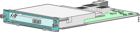
Port Adapter Overview
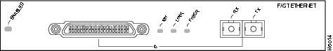
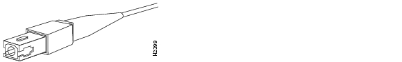
The PA-FE-TX and PA-FE-FX single-width port adapters provide a 100-Mbps, 100BASE-T Fast Ethernet interface and support both full-duplex and half-duplex operation. Refer to the "Fast Ethernet Overview" section for additional information. Figure 1-1 shows the PA-FE-TX, and Figure 1-2 shows the PA-FE-FX.
Figure 1-1 PA-FE-TX—Faceplate View
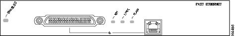
Figure 1-2 PA-FE-FX—Faceplate View
IEEE 802.3u 100BASE-T Specifications
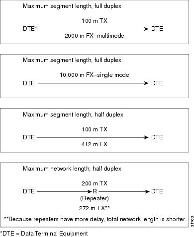
This section provides specifications for IEEE 802.3u 100BASE-T. Table 1-1 provides cabling specifications for 100BASE-TX Fast Ethernet transmission over UTP and foil twisted-pair (FTP), and 100BASE-FX Fast Ethernet over fiber-optic cables. It also summarizes IEEE 802.3u 100BASE-TX and 100BASE-FX physical characteristics. (See Figure 1-3).
|
|
|
|
|
|---|---|---|---|
Cable specification |
62.5/125 micron multimode optical fiber |
9/125 micron single mode optical fiber |
|
Maximum segment length3 (half-duplex) |
100 m (328 ft) |
412 m (1351.71 ft) |
N/A |
Maximum segment length (full-duplex)3 |
100 m (328 ft) |
2000 m (6561.68 ft) |
10,000 m (32808.40 ft) |
Maximum network length (half-duplex, one repeater)4 |
200 m (656.17 ft) |
272 m (892.39 ft) |
N/A |
Data rate |
100 Mbps |
100 Mbps |
100 Mbps |
Signaling method |
4B/5B block coded, scrambled, with MLT-3 line coding |
4B/5B block coded, with NRZI line coding |
4B/5B block coded, with NRZI line coding |
Connector |
RJ-45 |
Single mode SC-type: dual simplex or single duplex for Rx and Tx |
Single mode SC-type: dual simplex or single duplex for Rx and Tx |
Topology |
Star/hub |
Star/hub |
Star/hub |
1 EIA/TIA-568 or EIA-TIA-568 TSB-36 compliant. 2 Cisco does not supply Category 5 UTP RJ-45 cables. However, they are available commercially. 3 Data Terminal Equipment (DTE to DTE), see Figure 1-3. 4 DTE to Repeater to DTE, see Figure 1-3. |
Figure 1-3 Maximum Segment and Network Lengths—100BASE--FX adn 100BASE--TX
LEDs
The PA-FE-TX and the PA-FE-FX have an ENABLED LED, standard on all port adapters, and a bank of three status LEDs for the ports. After system initialization, the ENABLED LED lights to indicate that the PA-FE-TX or PA-FE-FX has been enabled for operation. (See Figure 1-4.)
Figure 1-4 LEDs on the PA-FE Port Adapter—Partial Faceplate View of PA-FE-TX
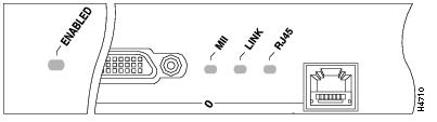
Table 1-2 lists port LED colors and indications.
Either the MII LED or the RJ-45 (or fiber) LED should be on at any one time; never both.
Cables, Connectors, and Pinouts
PA-FE-TX Connectors
The Fast Ethernet port on the PA-FE-TX has an RJ-45 connector to attach to Category 5 foil twisted-pair (FTP) for 100BASE-TX. The MII connector permits connection through external transceivers to multimode fiber for 100BASE-FX, or to Category 3, 4, and 5 FTP for 100BASE-T4 physical media. Only one connector can be used at a time. The RJ-45 connection does not require an external transceiver. The MII connection (a 40-pin, D-shell type connector) requires an external physical sublayer (PHY) and an external transceiver.
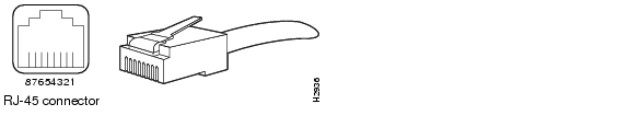
Figure 1-5 shows the RJ-45 cable connector. Cisco Systems does not supply Category 5 FTP RJ-45 cables; these cables are available commercially. Table 1-4 lists the pinouts for the PA-FE-TX RJ-45 connectors.
Figure 1-5 PA-FE-TX RJ-45 Connections—Plug and Receptacle
|
|
|
|---|---|
1 |
Transmit data + (TxD+) |
2 |
TxD- |
3 |
Receive data + (RxD+) |
6 |
RxD- |
Note ![]() Proper common-mode line terminations should be used for the unused Category 5, FTP cable pairs 4/5 and 7/8. Common-mode termination reduces the contributions to electromagnetic interference (EMI) and susceptibility to common-mode sources. Wire pairs 4/5 and 7/8 are actively terminated in the RJ-45, 100BASE-TX port circuitry in the PA-FE-TX.
Proper common-mode line terminations should be used for the unused Category 5, FTP cable pairs 4/5 and 7/8. Common-mode termination reduces the contributions to electromagnetic interference (EMI) and susceptibility to common-mode sources. Wire pairs 4/5 and 7/8 are actively terminated in the RJ-45, 100BASE-TX port circuitry in the PA-FE-TX.
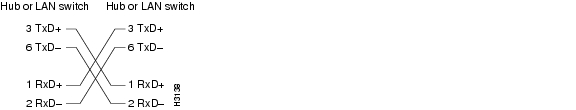
Depending on your RJ-45 interface cabling requirements, use the pinouts in Figure 1-6 and Figure 1-7.
Figure 1-6 Straight-Through Cable Pinout—PA-FE-TX RJ-45 Connection to a Hub or Repeater
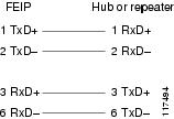
Figure 1-7 Crossover Cable Pinout—PA-FE-TX RJ-45 Connections Between Hubs and Repeaters
PA-FE-FX Connectors
The Fast Ethernet ports on the PA-FE-FX port adapter have an SC-type fiber-optic connector for 100BASE-FX, and an MII connector that permits connection through external transceivers to multimode fiber for 100BASE-FX, or to Category 3, 4, and 5 FTP or STP for 100BASE-T4 physical media. Only one connection can be used at a time. The MII connection (a 40-pin, D-shell type connector) requires an external physical sublayer (PHY) and an external transceiver.
Figure 1-8 shows the duplex SC connector (one required for both transmit and receive), and Figure 1-9 show the simplex SC connector (two required, one for each transmit and receive) used for PA-FE-FX optical-fiber connections. These multimode optical-fiber cables are commercially available and are not available from Cisco Systems.
Figure 1-8 PA-FE-FX Duplex SC Connector
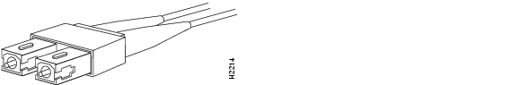
Figure 1-9 PA-FE-FX Simplex SC Connector
MII Connection
Depending on the type of media you use between the MII connection on the port adapter and your switch or hub, the network side of your 100BASE-T transceiver should be appropriately equipped with SC-type connectors (for optical fiber), BNC connectors, and so forth. Figure 1-10 shows the pin orientation of the female MII connector on the port adapter.
The MII receptacle uses two 56 screw-type locks, called jackscrews (shown in Figure 1-10), to secure the cable or transceiver to the MII port. MII cables and transceivers have knurled thumbscrews that you fasten to the jackscrews on the PA-FE-TX MII connector. Use the jackscrews to provide strain relief for your MII cable.

Figure 1-10 PA-FE-TX or PA-FE-FX MII Connection—Receptacle
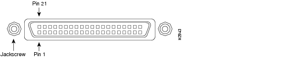
Table 1-4 lists the MII connector pinouts. MII cables are available commercially and are not available from Cisco Systems. Table 1-4 refers to MII cables used between the MII connector on the PA-FE-TX and an appropriate transceiver. The connection between this transceiver and your network can be Category 3, 4, or 5, 150-ohm FTP, or multimode optical fiber.
|
|
|
|
|
|
|---|---|---|---|---|
14-17 |
- |
Yes |
- |
Transmit Data (TxD) |
12 |
Yes |
- |
- |
Transmit Clock (Tx_CLK)2 |
11 |
- |
Yes |
- |
Transmit Error (Tx_ER) |
13 |
- |
Yes |
- |
Transmit Enable (Tx_EN) |
3 |
- |
Yes |
- |
MII Data Clock (MDC) |
4-7 |
Yes |
- |
- |
Receive Data (RxD) |
9 |
Yes |
- |
- |
Receive Clock (Rx_CLK) |
10 |
Yes |
- |
- |
Receive Error (Rx_ER) |
8 |
Yes |
- |
- |
Receive Data Valid (Rx_DV) |
18 |
Yes |
- |
- |
Collision (COL) |
19 |
Yes |
- |
- |
Carrier Sense (CRS) |
2 |
- |
- |
Yes |
MII Data Input/Output (MDIO) |
22-39 |
- |
- |
- |
Common (ground) |
1, 20, 21, 40 |
- |
- |
- |
+5.0 volts (V) |
1 Any pins not indicated are not used. 2 Tx_CLK and Rx_CLK are generated by the external transceiver. |
Port Adapter Slot Locations on the Supported Platforms
This section discusses port adapter slot locations on the supported platforms. The illustrations that follow summarize slot location conventions on each platform:
•![]() Catalyst 5000 Family Switches with RSM/VIP2 Slot Numbering
Catalyst 5000 Family Switches with RSM/VIP2 Slot Numbering
•![]() Cisco 7000 Series Routers with VIP Slot Numbering
Cisco 7000 Series Routers with VIP Slot Numbering
•![]() Cisco 7100 Series Routers Slot Numbering
Cisco 7100 Series Routers Slot Numbering
•![]() Cisco 7200 Series Routers, Cisco 7200 VXR Routers, and Cisco uBR7200 Series Routers Slot Numbering
Cisco 7200 Series Routers, Cisco 7200 VXR Routers, and Cisco uBR7200 Series Routers Slot Numbering
•![]() Cisco 7301 Router Slot Numbering
Cisco 7301 Router Slot Numbering
•![]() Cisco 7304 PCI Port Adapter Carrier Card Slot Numbering
Cisco 7304 PCI Port Adapter Carrier Card Slot Numbering
•![]() Cisco 7401ASR Router Slot Numbering
Cisco 7401ASR Router Slot Numbering
•![]() Cisco 7500 Series Routers with VIP Slot Numbering
Cisco 7500 Series Routers with VIP Slot Numbering
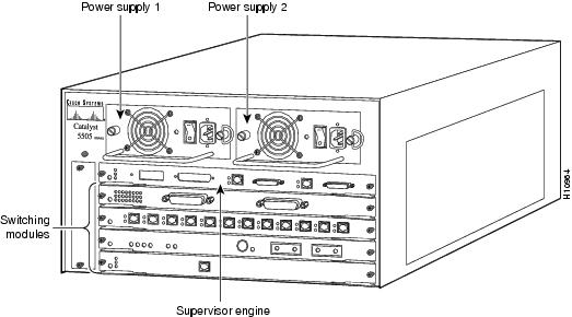
Catalyst 5000 Family Switches with RSM/VIP2 Slot Numbering
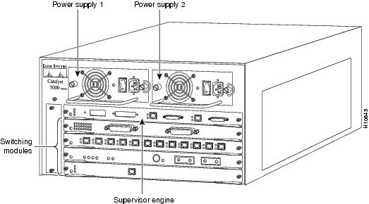
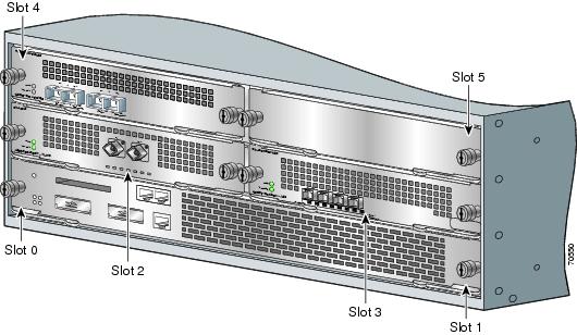
The Catalyst 5000 switch chassis has five slots. (See Figure 1-11.) Slot 1 is for the supervisor engine. Slots 2 through 5 are available for modules.
Figure 1-11 Catalyst 5000 Switch with Modules Installed
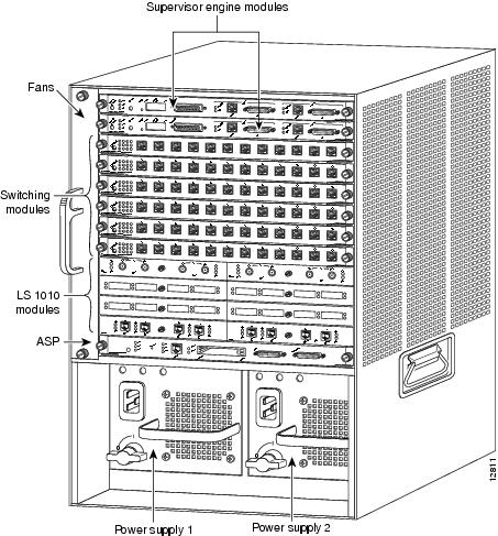
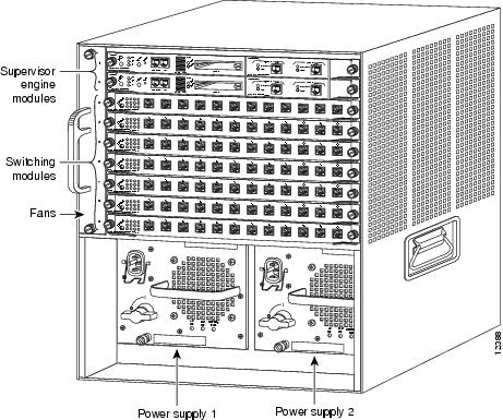
The Catalyst 5500 switch chassis has 13 slots. (See Figure 1-12.) Slot 1 is for the supervisor engine. Slot 2 can contain an additional redundant supervisor engine. If a redundant supervisor engine is not required, slot 2 through 12 are available for modules. Slot 13 is a dedicated slot for the ATM Switch Processor (ASP) module or the Catalyst 8510 Campus Switch Router (CSR) switch route processor (SRP). When using the ASP in slot 13, the Catalyst 5500 Switch accepts LightStream 1010 ATM port adapters in slots 9 through 12. When using the Catalyst 8510 CSR SRP in slot 13, the Catalyst 5500 switch accepts Catalyst 8510 CSR modules in slots 9 through 12.
Figure 1-12 Catalyst 5500 Switch with Modules Installed
The Catalyst 5505 switch chassis has five slots. (See Figure 1-13.) Slot 1 is for the supervisor engine. Slot 2 can contain an additional redundant supervisor engine. If a redundant supervisor engine is not required, slots 2 through 5 are available for modules.
Figure 1-13 Catalyst 5505 Switch with Modules Installed
The Catalyst 5509 switch chassis has nine slots. (See Figure 1-14.) Slot 1 is for the supervisor engine. Slot 2 can contain a redundant supervisor engine. If a redundant supervisor engine is not required, slots 2 through 9 are available for modules.
Figure 1-14 Catalyst 5509 Switch with Modules Installed
Note ![]() Refer to the Catalyst 5000 Series Route Switch Module Installation and Configuration Note for any additional slot restrictions for the Catalyst RSM/VIP2.
Refer to the Catalyst 5000 Series Route Switch Module Installation and Configuration Note for any additional slot restrictions for the Catalyst RSM/VIP2.
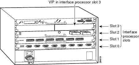
Cisco 7000 Series Routers with VIP Slot Numbering
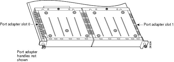
Figure 1-15 shows a partial view of a VIP motherboard with installed modules. With the motherboard oriented as shown in Figure 1-15, the left module is in slot 0, and the right module is in slot 1. The slot numbering is the same for the Catalyst RSM/VIP2. The slots are always numbered 0 and 1.
Figure 1-15 VIP Motherboard with Two Modules Installed—Horizontal Orientation
Note ![]() In the Cisco 7000 chassis, the VIP motherboard is installed vertically. In the Cisco 7010 chassis, the VIP motherboard is installed horizontally.
In the Cisco 7000 chassis, the VIP motherboard is installed vertically. In the Cisco 7010 chassis, the VIP motherboard is installed horizontally.
Figure 1-16 shows the Cisco 7000 with modules installed in slots 0 through 4. Figure 1-17 shows the Cisco 7010 with modules installed in slots 0, 1, and 2.
Figure 1-16 Cisco 7000 Interface Slot Numbers
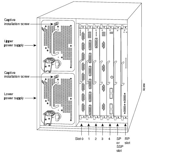
Figure 1-17 Cisco 7010 Interface Slot Numbers
Cisco 7100 Series Routers Slot Numbering
The PA-FE-TX and PA-FE-FX can be installed in port adapter slot 3 in Cisco 7120 series routers, and in port adapter slot 4 in Cisco 7140 series routers. Figure 1-18 shows a Cisco 7120 with a port adapter installed in slot 3. Figure 1-19 shows a Cisco 7140 with a port adapter installed in slot 4.
Figure 1-18 Port Adapter Slots in the Cisco 7100 Series Router—Cisco 7120 Series
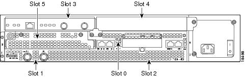
Figure 1-19 Port Adapter Slots in the Cisco 7100 Series Router—Cisco 7140 Series
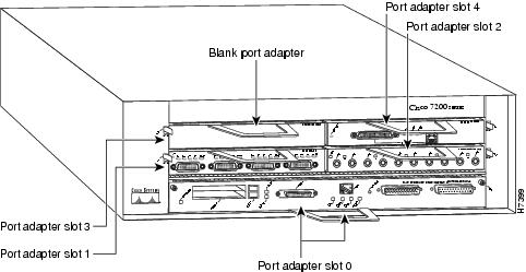
Cisco 7200 Series Routers, Cisco 7200 VXR Routers, and Cisco uBR7200 Series Routers Slot Numbering
Slots in the Cisco 7202 router are numbered from left to right, slot 1 and slot 2. (See Figure 1-20.)
Figure 1-20 Module Slots in the Cisco 7202
Slots in the Cisco 7204 router are numbered from left to right, beginning with slot 1 and continuing through slot 4. Slot 0 is the Fast Ethernet port on the I/O controller. (See Figure 1-21.)
Figure 1-21 Module Slots in the Cisco 7204
The Cisco 7204VXR has four slots (slot 1 through slot 4) for modules, one slot for an input/output (I/O) controller, and one slot for a network processing engine or network services engine. You can place the modules in any of the four available slots. (See Figure 1-22.)
Figure 1-22 Module Slots in the Cisco 7204VXR
Slots in the Cisco 7206 are numbered from 1 through 6; slot 0 is reserved for the optional Fast Ethernet port on the I/O controller—if present. (See Figure 1-23.)
Figure 1-23 Module Slots in the Cisco 7206
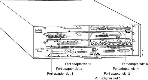
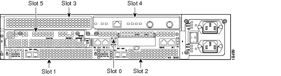
The Cisco 7206VXR has six slots (slot 1 through slot 6) for modules, one slot for an input/output (I/O) controller, and one slot for a network processing engine or network services engine. You can place the modules in any of the six available slots. (See Figure 1-24.)
Figure 1-24 Module Slots in the Cisco 7206VXR
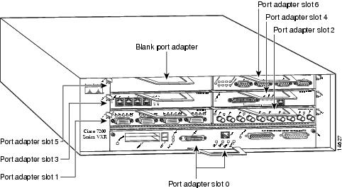
Figure 1-25 shows that slot 1 of the Cisco uBR7223 is the slot in which modules are installed. (Slot 0 is always reserved for the Fast Ethernet port on the I/O controller—if present.)
Figure 1-25 Module Slots in the Cisco uBR7233
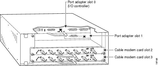
Figure 1-26 shows the slot numbering of modules installed on a Cisco uBR7246 router. The slots are numbered slot 1 and slot 2 for the Cisco uBR7246 router. (Slot 0 is always reserved for the Fast Ethernet port on the I/O controller—if present.)
Figure 1-26 Module Slots in the Cisco uBR7246
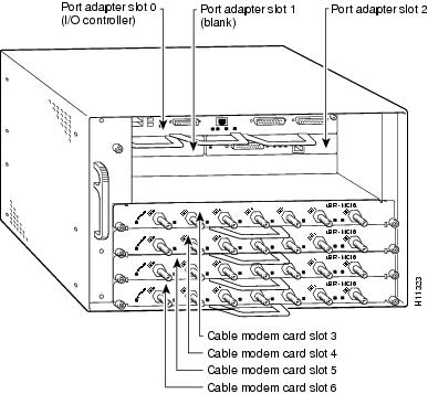
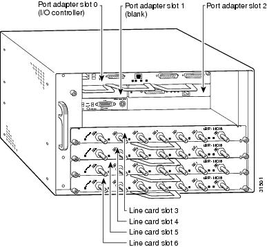
In the Cisco uBR7246 VXR, slot 0 is the Fast Ethernet port on the I/O controller. Port adapter slots are numbered 1 and 2 and line card slots are numbered from 3 to 6. (See Figure 1-27.)
Figure 1-27 Module Slots in the Cisco uBR7246VXR
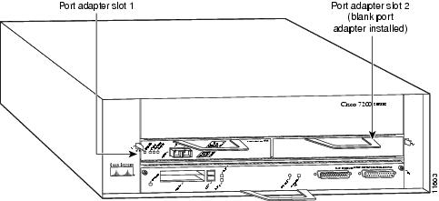
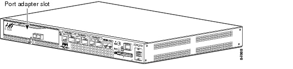
Cisco 7301 Router Slot Numbering
Figure 1-28 shows the front view of a Cisco 7301 router with a port adapter installed. There is only one port adapter slot in a Cisco 7301 router.
Figure 1-28 Cisco 7301 Router with a Port Adapter Installed
Cisco 7304 PCI Port Adapter Carrier Card Slot Numbering
The Cisco 7304 PCI Port Adapter Carrier Card accepts one single-width port adapter. Figure 1-29 shows a Cisco 7304 PCI Port Adapter Carrier Card with a port adapter installed.
Figure 1-29 Cisco 7304 PCI Port Adapter Carrier Card—Port Adapter Installed
The Cisco 7304 PCI Port Adapter Carrier Card installs in Cisco 7304 router module slots 2 through 5. See Figure 1-30 for module slot numbering on a Cisco 7304 router.
Figure 1-30 Module Slots on the Cisco 7304 Router
Cisco 7401ASR Router Slot Numbering
Figure 1-31 shows the front view of a Cisco 7401ASR router with a port adapter installed. There is only one port adapter slot in a Cisco 7401ASR router.
Figure 1-31 Cisco 7401ASR Router with a Port Adapter Installed
Cisco 7500 Series Routers with VIP Slot Numbering
Figure 1-32 shows a partial view of a VIP motherboard with installed modules. With the motherboard oriented as shown in Figure 1-32, the left module is in module slot 0, and the right module is in module slot 1. The slots are always numbered 0 and 1.
Figure 1-32 VIP Motherboard with Two Modules Installed—Horizontal Orientation
Note ![]() In the Cisco 7507 and Cisco 7513 chassis, the VIP motherboard is installed vertically.
In the Cisco 7507 and Cisco 7513 chassis, the VIP motherboard is installed vertically.
In the Cisco 7505 chassis, the VIP motherboard is installed horizontally.
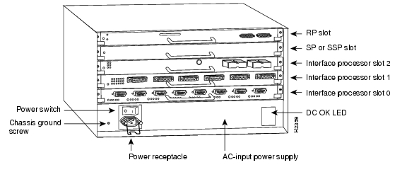
Interface processor slots in the Cisco 7500 series routers are numbered as shown in Figure 1-33.
Figure 1-33 Interface Slot Numbers—Cisco 7505 Shown
Identifying Interface Addresses
This section describes how to identify interface addresses for the PA-FE-TX and PA-FE-FX in supported platforms. Interface addresses specify the actual physical location of each interface on a router or switch.
Interfaces on the PA-FE-TX and PA-FE-FX installed in a router maintain the same address regardless of whether other port adapters are installed or removed. However, when you move a port adapter to a different slot, the first number in the interface address changes to reflect the new port adapter slot number.
Interfaces on a PA-FE-TX and PA-FE-FX installed in a VIP maintain the same address regardless of whether other interface processors are installed or removed. However, when you move a VIP to a different slot, the interface processor slot number changes to reflect the new interface processor slot.
The following subsections describe the interface address formats for specific platforms:
•![]() Interface Addresses of the Catalyst 5000 Family Switches with RSM/VIP2
Interface Addresses of the Catalyst 5000 Family Switches with RSM/VIP2
•![]() Interface Addresses of Cisco 7000 Series Routers with VIP
Interface Addresses of Cisco 7000 Series Routers with VIP
•![]() Interface Addresses of Cisco 7100 Series Routers
Interface Addresses of Cisco 7100 Series Routers
•![]() Interface Addresses of Cisco 7301 Router
Interface Addresses of Cisco 7301 Router
•![]() Interface Addresses Cisco 7304 PCI Port Adapter Carrier Card
Interface Addresses Cisco 7304 PCI Port Adapter Carrier Card
•![]() Interface Addresses of Cisco 7401ASR Router
Interface Addresses of Cisco 7401ASR Router
•![]() Interface Addresses of Cisco 7500 Series Routers with VIP
Interface Addresses of Cisco 7500 Series Routers with VIP
Interface Addresses of the Catalyst 5000 Family Switches with RSM/VIP2
The interface address for a module on the Catalyst 5000 family switch with RSM/VIP2 is composed of a two-part number in the format slot/port-number. The first number identifies the slot in which the module is installed. Module slots are numbered from top to bottom starting with 1. The second number identifies the physical port number on the module. The port numbers always begin at 1 and are numbered from left to right, facing the rear of the switch. In some cases, the ports are physically identified on the module front panel. The number of additional ports (n/1, n/2, and so on) depends on the number of ports available on the module.
Interface ports maintain the same address regardless of whether other modules are installed or removed. However, when you move a module to a different slot, the first number in the address changes to reflect the new slot number. For example, on a 12-port 100BASE-TX switching module in slot 2, the address of the left port is 2/1 and the address of the right port is 2/12. If you remove the 12-port 100BASE-TX switching module from slot 2 and install it in slot 4, the addresses of those same ports become 4/1 through 4/12.
Interface Addresses of Cisco 7000 Series Routers with VIP
The Cisco 7000 series routers accepts modules installed with a Versatile Interface Processor (VIP). The interface address of the modules is composed of a three-part number in the format slot/bay/port-number. The first number identifies the slot of the router in which the VIP is installed (slot 0 through 12, depending on the number of slots in the router). These module slots are numbered from bottom to top starting with 0.
The second number identifies the bay of the VIP in which the additional module is installed (0 or 1). The bays are numbered from left to right on the VIP.
The third number identifies the physical port number on the module. The port numbers always begin at 1 and are numbered from left to right. The number of additional ports (n/1, n/2, and so on) depends on the number of ports on the module.
Note ![]() Although the slots in the 7-slot Cisco 7000 are vertically oriented and those in the 5-slot Cisco 7010 are horizontally oriented, all Cisco 7000 series routers use the same method for slot and interface port numbering.
Although the slots in the 7-slot Cisco 7000 are vertically oriented and those in the 5-slot Cisco 7010 are horizontally oriented, all Cisco 7000 series routers use the same method for slot and interface port numbering.
If the VIP is installed in slot 3, and the module is installed in bay 1 of the VIP and has a total of 8 ports, the interface addresses of the module are 3/1/0 through 3/1/7 (slot 3, bay 1, ports 0 through 7). If you remove the VIP with the module from slot 3 and install it in slot 2, the interface addresses become 2/1/0 through 2/1/7. I f the module was in bay 0 of the VIP, these same interface addresses would be numbered 2/0/0 through 2/0/7.
Interface Addresses of Cisco 7100 Series Routers
The interface address for a module installed on a Cisco 7100 series router is composed of a two-part number in the format slot/port-number. The first number identifies the slot of the router in which the module is installed—slot 3 on the Cisco 7120 series routers and slot 4 on the Cisco 7140 series routers.
The second number identifies the physical interface port number on the module.
For example, if the 2-port module is installed in a Cisco 7120, and therefore in slot 3, the interface address of the left port is 3/0 and the interface address of the right port is 3/1.
If you remove the module from the Cisco 7120, and install it in a Cisco 7140, and therefore slot 4, the addresses of the interface ports become 4/0 and 4/1.
Interface Addresses of Cisco 7200 Series Routers, Cisco 7200 VXR Routers, and Cisco uBR7200 Series Routers
The interface address for a module installed in Cisco 7200 series routers, Cisc 7200 VXR routers, or Cisco uBR7200 series routers is composed of a two-part number in the format slot/port-number.
In Cisco 7200 series routers, slots are numbered from the lower left to the upper right, beginning with slot 1 and continuing through slot 2 for the Cisco 7202, slot 4 for the Cisco 7204 and Cisco 7204VXR, and slot 6 for the Cisco 7206 and Cisco 7206VXR. (Slot 0 is reserved for the optional Fast Ethernet port on the I/O controller—if present.)
The interface addresses of a 4-port module installed in slot 1 would be 1/0 through 1/3 (slot 1 and interface port 0 through port 3). If the 4-port module was installed in slot 4, these same interfaces would be numbered 4/0 through 4/3 (slot 4 and interface port 0 through port 3).
In Cisco uBR7200 series routers, slots are numbered slot 1 and slot 2 for the Cisco uBR7246 and Cisco uBR7246VXR and slot 1 for the Cisco uBR7223. (Slot 0 is always reserved for the Fast Ethernet port on the I/O controller—if present.) The individual interfaces always begin with 0. The number of additional interfaces depends on the number of interface ports on a module.
The interface addresses of a module installed in slot 2 would be 2/0 and 2/1 (slot 2 and interface ports 0 and 1). If a module is installed in slot 1, these same interface addresses would be 1/0 and 1/1 (slot 1 and interface ports 0 and 1).
Interface Addresses of Cisco 7301 Router
There is only one slot on the Cisco 7301 router that accepts modules and it is numbered as slot 1. The interface address is composed of a two-part number in the format slot/port-number. For example, if a 2-port module is installed on a Cisco 7301 router, the two interface addresses would be 1/0 and 1/1 from left to right.
Interface Addresses Cisco 7304 PCI Port Adapter Carrier Card
This section describes how to identify the interface addresses used for the PA-FE-TX and PA-FE-FX in the Cisco 7304 PCI Port Adapter Carrier Card in Cisco 7304 routers. The interface address is made of a two-part number in the format port-adapter-slot-number/interface-port-number.
The Cisco 7304 PCI Port Adapter Carrier Card installs into Cisco 7304 router module slots 2 through 5 (See Figure 1-30.) The port-adapter-slot-number is the Cisco 7304 router module slot number. For example, the interface address of port 0 on a PA-FE-TX, in which the Cisco 7304 PCI Port Adapter Carrier Card is installed in Cisco 7304 router module slot 3, would be numbered 3/0.
Interface Addresses of Cisco 7401ASR Router
There is only one slot on the Cisco 7401ASR router that accepts modules and it is numbered as slot 1. The interface address is composed of a two-part number in the format slot/port-number. For example, if a 2-port module is installed on a Cisco 7401ASR router, the two interface addresses would be 1/0 and 1/1 from left to right.
Interface Addresses of Cisco 7500 Series Routers with VIP
The Cisco 7500 series routers accepts modules installed with a Versatile Interface Processor (VIP). The interface address of the modules is composed of a three-part number in the format slot/bay/port-number. The first number identifies the slot of the router in which the VIP is installed (slot 0 through 12, depending on the number of slots in the router). These module slots are numbered from bottom to top starting with 0.
The second number identifies the bay of the VIP in which the additional module is installed (0 or 1). The bays are numbered from left to right on the VIP.
The third number identifies the physical port number on the module. The port numbers always begin at 1 and are numbered from left to right. The number of additional ports (n/1, n/2, and so on) depends on the number of ports on the module.
Note ![]() Although the processor slots in the 7-slot Cisco 7507 and the 13-slot Cisco 7513 and Cisco 7576 are vertically oriented and those in the 5-slot Cisco 7505 are horizontally oriented, all Cisco 7500 series routers use the same method for slot and interface port numbering.
Although the processor slots in the 7-slot Cisco 7507 and the 13-slot Cisco 7513 and Cisco 7576 are vertically oriented and those in the 5-slot Cisco 7505 are horizontally oriented, all Cisco 7500 series routers use the same method for slot and interface port numbering.
If the VIP is installed in slot 3, and the module is installed in bay 1 of the VIP and has a total of 8 ports, the interface addresses of the module are 3/1/0 through 3/1/7 (slot 3, bay 1, ports 0 through 7). If you remove the VIP with the module from slot 3 and install it in slot 2, the interface addresses become 2/1/0 through 2/1/7. If the module was in bay 0 of the VIP, these same interface addresses would be numbered 2/0/0 through 2/0/7.
 Feedback