- Title and copyright: PA-5EFL Ethernet 10BaseT-FL Port Adapter Installation and Configuration
- Overview: PA-5EFL Ethernet 10BaseT-FL Port Adapter Installation and Configuration
- Preparing to Install the PA-5EFL Ethernet 10BaseT-FL Port Adapter
- Removing and Installing the PA-5EFL Ethernet 10BaseT-FL Port Adapter
- Configuring the PA-5EFL Ethernet 10BaseT-FL Port Adapter
Overview
This chapter describes the Cisco PA-5EFL port adapter and contains the following sections:
•![]() Ethernet and Ethernet 10Base-FL Overview
Ethernet and Ethernet 10Base-FL Overview
•![]() IEEE 802.3 10Base-FL Specifications
IEEE 802.3 10Base-FL Specifications
•![]() LEDs
LEDs
•![]() Port Adapter Slot Locations on the Supported Platforms
Port Adapter Slot Locations on the Supported Platforms
•![]() Identifying Interface Addresses
Identifying Interface Addresses
Port Adapter Overview
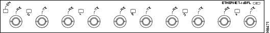
The PA-5EFL port adapter, shown in Figure 1-1, provides up to five IEEE 802.3 Ethernet 10Base-FL interfaces for the chassis. The PA-5EFL network interfaces provide a direct connection between the high-speed bus in the router and external networks. Each Ethernet 10Base-FL interface allows a maximum bandwidth of 10 Mbps, for a maximum aggregate bandwidth of 50 Mbps, half-duplex. Each 10Base-FL interface uses two multimode ST-type receptacles for receive (RX) and transmit (TX). All five ports run at wire speed.
Figure 1-1 PA-5EFL—Faceplate View
Ethernet and Ethernet 10Base-FL Overview
The term Ethernet is commonly used for all carrier sense multiple access/collision detection (CSMA/CD) local-area networks (LANs) that generally conform to Ethernet specifications, including IEEE 802.3. Ethernet Version 2 and IEEE 802.3 were based on, and developed shortly after, Ethernet Version 1. The slight differences between Ethernet and IEEE 802.3 are implemented in hardware, and both are supported automatically by the PA-5EFL port adapter without any hardware configuration changes. Together, Ethernet and IEEE 802.3 are the most widely used LAN protocols. They are well suited to applications where a local communication medium must carry sporadic, occasionally heavy traffic at high-peak data rates.
The term 10Base-FL is an abbreviation for 10 Mbps transmission, Baseband medium, F for fiber, and L for link, as defined in the 10Base-FL specification. The Ethernet specifications call the 5EFL device a transceiver, and it is connected to the station with a transceiver cable. The PA-5EFL is not an end station. The IEEE 802.3 specifications refer to the same type of device as a media attachment unit (MAU). Stations on a CSMA/CD LAN can access the network at any time. Before sending data, the station listens to the network to see of it is already in use. If it is, the station waits until the network is not in use, and then transmits. A collision occurs when two stations listen for network traffic, hear none, and transmit simultaneously. When this happens, both transmissions are damaged, and the stations must retransmit. The stations detect the collision and use backoff algorithms to determine when they should retransmit.
Both Ethernet and IEEE 802.3 are broadcast networks, which means that all stations see all transmissions. Each station must examine received frames to determine whether it is the intended destination and, if it is, pass the frame to a higher protocol layer for processing. IEEE 802.3 specifies several different physical layers, and Ethernet defines only one. Each IEEE 802.3 physical layer protocol has a name that summarizes its characteristics in the format speed/signaling method/segment length where speed is the LAN speed in Mbps, signaling method is the signaling method used (either baseband or broadband), and segment length is the maximum length between stations in hundreds of meters. The maximum distances for Ethernet network segments and connections depend on the type of transmission cable used; for example, fiber-optic cable (10Base-FL).
IEEE 802.3 10Base-FL Specifications
Table 1-1 summarizes the characteristics of IEEE 802.3 Ethernet and Ethernet 10Base-FL.
Table 1-2 lists the distance limitations for 10-Mbps transmission over multimode optical-fiber cables.
|
|
|
|---|---|
Cable specification |
Multimode fiber-optic cable1 |
Maximum segment lengths |
400 m (1,312 ft) for any repeater-to-DTE fiber segment |
1 Cisco Systems does not supply fiber-optic cables; these cables are available commercially. |
Table 1-3 lists multimode optical-fiber parameters.
|
|
|
|---|---|
Size |
62.5/125 micrometer (nominal diameter) optical fiber1 |
Attenuation |
~ 3.75 dB/km, at 850 nanometers (nm) |
Insertion loss |
< 12.5 dB, at 850 nm |
Bandwidth |
> 160MHzkm, at 850 nm |
Propagation delay |
~ 5 microseconds/km |
1 Specified in IEC Publication 793-2[14]. |
LEDs
The PA-5EFL port adapter has one row of five status LEDs (one for each port), and one enabled LED. (See Figure 1-2.) The green-colored LED for each port indicates port status.
Figure 1-2 LEDs on the Cisco 5EFL Port Adapter—Partial Faceplate View
After system initialization, the enabled LED goes on to indicate that the port adapter has been enabled for operation.
The following conditions must be met before the PA-5EFL is enabled:
•![]() The PA-5EFL is correctly connected and receiving power.
The PA-5EFL is correctly connected and receiving power.
•![]() A valid system software image for the port adapter has been downloaded successfully.
A valid system software image for the port adapter has been downloaded successfully.
•![]() The system recognizes the PA-5EFL or a VIP with a PA-5EFL.
The system recognizes the PA-5EFL or a VIP with a PA-5EFL.
If any of the above conditions are not met, or if the initialization fails for other reasons, the enabled LED does not go on.
Table 1-4 lists LED colors and indications.
|
|
|
|
|
ENABLED |
Green |
On |
Port adapter is enabled for operation. |
0 through 4 |
Green |
On |
Port adapter is receiving a signal from the network. |
Cables and Connectors
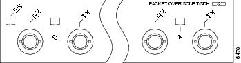
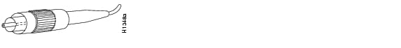
The interface connectors on the PA-5EFL port adapter are five pairs of ST-type receptacles, designated as RX and TX. You can use all five connection pairs simultaneously or any combination of each pair individually. Each connection pair supports IEEE 802.3 and Ethernet 10Base-FL interfaces compliant with appropriate standards. Figure 1-3 shows the ST fiber-optic cable plug used for RX and TX connections.
Figure 1-3 Ethernet 10Base-FL Fiber-Optic Cable Plug—ST-Type Connector

Note ![]() The PA-5EFL interfaces on a VIP are configured for 10 Mbps, half-duplex, for a maximum aggregate bandwidth of 50 Mbps for half-duplex. Cisco Systems does not supply ST-type optical-fiber cables; these cables are available commercially. For ST-type, multimode optical-fiber cable specifications and transmission distance limitations and requirements, refer to the section "IEEE 802.3 10Base-FL Specifications" section.
The PA-5EFL interfaces on a VIP are configured for 10 Mbps, half-duplex, for a maximum aggregate bandwidth of 50 Mbps for half-duplex. Cisco Systems does not supply ST-type optical-fiber cables; these cables are available commercially. For ST-type, multimode optical-fiber cable specifications and transmission distance limitations and requirements, refer to the section "IEEE 802.3 10Base-FL Specifications" section.
Port Adapter Slot Locations on the Supported Platforms
This section discusses port adapter slot locations on the supported platforms. The illustrations that follow summarize slot location conventions on each platform.
Cisco 7100 Series Routers Slot Numbering
The PA-5EFL port adapter can be installed in port adapter slot 3 in Cisco 7120 series routers, and in port adapter slot 4 in Cisco 7140 series routers. Figure 1-4 shows a Cisco 7120 with a port adapter installed in slot 3. Figure 1-5 shows a Cisco 7140 with a port adapter installed in slot 4.
Figure 1-4 Port Adapter Slots in the Cisco 7100 Series Router—Cisco 7120 Series Router
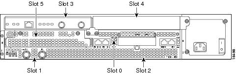
Figure 1-5 Port Adapter Slots in the Cisco 7100 Series Router—Cisco 7140 Series Router
Cisco 7200 Series and Cisco uBR7200 Series Routers Slot Numbering
Figure 1-6 shows a Cisco 7206 with port adapters installed. In the Cisco 7206 (including the Cisco 7206VXR as router shelves in a Cisco AS5800 Universal Access Server), port adapter slot 1 is in the lower left position, and port adapter slot 6 is in the upper right position. (The Cisco 7202 and Cisco 7204 are not shown; however, the PA-5EFL port adapter can be installed in any available port adapter slot.)
Figure 1-6 Port Adapter Slots in the Cisco 7206 Router
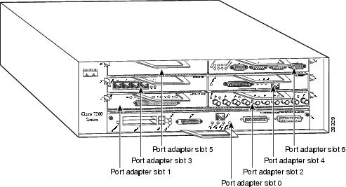
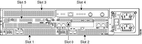
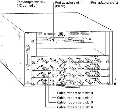
Figure 1-7 shows the slot numbering of port adapters in a Cisco uBR7246 series router. The port adapter slots are numbered slot 1 and slot 2 for the Cisco uBR7246. (Slot 0 is always reserved for the Fast Ethernet port on the I/O controller—if present.)
Figure 1-7 Port Adapter Slots in the Cisco uBR7246 Router
Cisco 7301 Router Slot Numbering
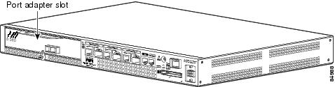
The Cisco 7301 router has one standard port adapter slot. See Figure 1-8.
Figure 1-8 Port Adapter Slot in the Cisco 7301 Router
VIP Slot Numbering
Figure 1-9 shows a partial view of a VIP motherboard with installed port adapters. With the motherboard oriented as shown in Figure 1-9, the left port adapter is in port adapter slot 0, and the right port adapter is in port adapter slot 1 The slots are always numbered 0 and 1.
Figure 1-9 VIP Motherboard with Two Port Adapters Installed-Horizontal Orientation
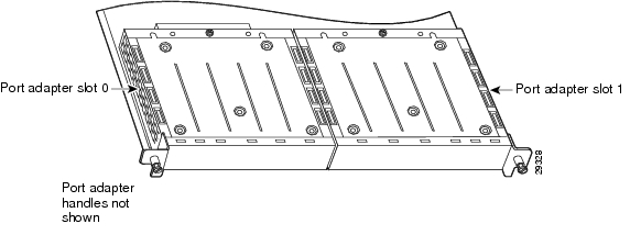
Note ![]() In the Cisco 7000, Cisco 7507, and Cisco 7513 chassis, the VIP motherboard is installed vertically. In the Cisco 7010 and Cisco 7505 chassis, the VIP motherboard is installed horizontally.
In the Cisco 7000, Cisco 7507, and Cisco 7513 chassis, the VIP motherboard is installed vertically. In the Cisco 7010 and Cisco 7505 chassis, the VIP motherboard is installed horizontally.
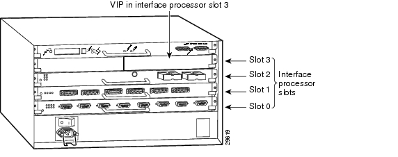
Interface processor slots are numbered as shown in Figure 1-10.
Figure 1-10 Interface Slot Numbers—Cisco 7505 Router Shown
Identifying Interface Addresses
This section describes how to identify interface addresses for the PA-5EFL port adapter in supported platforms. Interface addresses specify the actual physical location of each interface on a router or switch.
Interfaces on the PA-5EFL installed in a router maintain the same address regardless of whether other port adapters are installed or removed. However, when you move a port adapter to a different slot, the first number in the interface address changes to reflect the new port adapter slot number.
Interfaces on a PA-5EFL installed in a VIP maintain the same address regardless of whether other interface processors are installed or removed. However, when you move a VIP to a different slot, the interface processor slot number changes to reflect the new interface processor slot.
Note ![]() Interface ports are numbered from left to right starting with 0.
Interface ports are numbered from left to right starting with 0.
Table 1-5 explains how to identify interface addresses.
|
|
|
|
|
|---|---|---|---|
Cisco 7120 series routers |
Port-adapter-slot-number/interface-port-number |
Port adapter slot—always 3 Interface port—0 through 4 |
3/1 |
Cisco 7140 series routers |
Port-adapter-slot-number/interface-port-number |
Port adapter slot—always 4 Interface port—0 through 4 |
4/0 |
Cisco 7200 series routers |
Port-adapter-slot-number/interface-port-number |
Port adapter slot—0 through 6 (depends on the number of slots in the router)1 Interface port—0 through 4 |
1/0 |
Cisco uBR7246 router |
Port-adapter-slot-number/interface-port-number |
Port adapter slot—always 1 or 21 Interface port—0 through 4 |
1/2 |
Cisco 7301 router |
Port-adapter-slot-number/interface-port-number |
Port adapter slot always—1 Interface port—0 through 4 |
1/0 |
VIP in Cisco 7000 series or |
Interface-processor-slot-number/port-adapter-slot-number/ |
Interface processor slot—0 through 12 (depends on the number of slots in the router) Port adapter slot—always 0 or 1 Interface port—0 through 4 |
3/1/0 |
1 Port adapter slot 0 is reserved for the Fast Ethernet port on the I/O controller (if present). |
Cisco 7100 Series Routers Interface Addresses
This section describes how to identify the interface addresses used for the PA-5EFL port adapter in Cisco 7100 series routers. The interface address is composed of a two-part number in the format port-adapter-slot-number/interface-port-number. See Table 1-5 for the interface address format.
Cisco 7200 Series and Cisco uBR7200 Series Routers Interface Addresses
This section describes how to identify the interface addresses used for the PA-5EFL port adapter in Cisco 7200 series routers or Cisco uBR7200 series routers. The interface address is composed of a two-part number in the format port-adapter-slot-number/interface-port-number. SeeTable 1-5 for the interface address format.
In Cisco 7200 series routers, port adapter slots are numbered from the lower left to the upper right, beginning with port adapter slot 1 and continuing through port adapter slot 2 for the Cisco 7202, slot 4 for the Cisco 7204 and Cisco 7204VXR, and slot 6 for the Cisco 7206 and Cisco 7206VXR. (Port adapter slot 0 is reserved for the optional Fast Ethernet port on the I/O controller—if present.)
The interface addresses of the interfaces on the PA-5EFL port adapter in port adapter slot 1 are 1/0 through 1/4 (port adapter slot 1 and interfaces 0 through 4). If the PA-5EFL was in port adapter slot 4, these same interfaces would be numbered 4/0 through 4/4 (port adapter slot 4 and interfaces 0 through 4).
In the Cisco uBR7246 routers, port adapter slots are numbered slot 1 and slot 2. (Slot 0 is always reserved for the Fast Ethernet port on the I/O controller—if present.) The individual interfaces always begin with 0. The number of additional interfaces depends on the number of interface ports on a port adapter.
The interface addresses of the interfaces on a PA-5EFL port adapter in port adapter slot 2 are 2/0 through 2/4 (port adapter slot 2 and interfaces 0 through 4). If the PA-5EFL was in port adapter slot 1, these same interfaces would be numbered 1/0 through 1/4 (port adapter slot 1 and interfaces 0 through 4).
Cisco 7301 Router Interface Addresses
This section describes how to identify the interface addresses used for the PA-5EFL port adapter in Cisco 7301 router. The interface address is composed of a two-part number in the format port-adapter-slot-number/interface-port-number. See Table 1-5 for the interface address format.
The Cisco 7301 router has a single port adapter slot (slot 1). Slot 0 through slot 4 are reserved for the interface slots. The interface addresses of the interfaces on a PA-5EFL in port adapter slot 1 are 1/0 through 1/4 (port adapter slot 1 and interfaces 0 through 4).
VIP2 Interface Addresses
This section describes how to identify the interface addresses used for the PA-5EFL port adapter on a VIP2 in Cisco 7000 and Cisco 7500 series routers.
Note ![]() Although the processor slots in the 7-slot Cisco 7000 and Cisco 7505 and the 13-slot Cisco 7513 and Cisco 7576 are vertically oriented and those in the 5-slot Cisco 7010 and Cisco 7505 are horizontally oriented, all Cisco 7000 series and Cisco 7500 series routers use the same method for slot and port numbering.
Although the processor slots in the 7-slot Cisco 7000 and Cisco 7505 and the 13-slot Cisco 7513 and Cisco 7576 are vertically oriented and those in the 5-slot Cisco 7010 and Cisco 7505 are horizontally oriented, all Cisco 7000 series and Cisco 7500 series routers use the same method for slot and port numbering.
See Table 1-5 for the interface address format. The interface address is composed of a three-part number in the format interface-processor-slot-number/port-adapter-slot-number/interface-port-number.
If the VIP2 is inserted in interface processor slot 3, then the interface addresses of the PA-5EFL are 3/1/0 through 3/1/4 (interface processor slot 3, then the interface addresses 0 through 4). If the port adapter was in port adapter slot 0 on the VIP2, these same interface addresses would be numbered 3/0/0 through 3/0/4.
Note ![]() If you remove the VIP with the PA-5EFL port adapter from interface processor slot 3 and install it in interface processor slot 2, the interface addresses become 2/1/0 through 2/1/4.
If you remove the VIP with the PA-5EFL port adapter from interface processor slot 3 and install it in interface processor slot 2, the interface addresses become 2/1/0 through 2/1/4.
 Feedback